cat. no. i146e-en-01 r6y - xc/xg series - omron · 2018-05-22 · cat. no. i146e-en-01 r6y - xc/xg...
TRANSCRIPT

ZX-T Series
Cat. No. I146E-EN-01
R6Y - XC/XG series
USER´S MANUAL
Cat. No. I146E-EN-01 Note: Specifi cations subject to change without notice.
Authorized Distributor:
Printed in Europe
Cat. N
o. I146E-EN-01
SC
AR
A Robot, R
6Y - XC
/XG
seriesU
SERS M
AN
UA
L
SCARA RobotsTiny Series


Before using the robot (Be sure to read the following notes.) At this time, our thanks for your purchase of this OMRON X series SCARA robot.
(1) Please be sure to perform the following tasks before using the robot. Note that the robot may operate abnormally (abnormal vibration or noise) if
the following work is not carried out.
Before the X series is shipped, the position shown in "Chapter 7, 1-2 External view and dimensions" is adjusted as the origin position, and the standard coordinates are provisionally set.
1. Absolute ResetAbsolute reset must be carried out just once before the X series robot can be used.Once absolute reset is completed, it does not need to be carried out again when the power is turned ON the next time.Refer to "Chapter 4, 3. Adjusting the origin" in this manual and "Absolute Reset" in the "OMRON Robot Controller User's Manual" for details on absolute reset.
2. Setting the standard coordinatesSet the standard coordinates while referring to instructions in "5. Setting the Standard coordinates" in Chapter 4 of this manual and also to "Setting the Standard coordinates" in the "OMRON Robot Controller User's Manual".Robot malfunctions (vibration, noise) may occur if the standard coordinates are not set correctly.
Even though there is no problem with the robot, the following error messages are issued when the robot and controller are connected and power first turned on.(Actual error messages may differ according to how the robot and controller are connected.)
Error messages issued when robot & controller are connected (YRC)17.81 : D?.ABS.battery wire breakage17.92 : D?.Resolver disconnected during power off 17.93 : D?.Position backup counter overflow17.94 : D?.ABS.battery low voltage etc
(2) Caution when turning off the robot controller On the R6YXG120, R6YXG150, R6YXG180, R6YXG220 robots, the harness
exerts a large reaction force on the X and Y axis arms. When the power to the robot controller is turned off, the arm positions might move slightly due to the harness reaction force, depending on where the arms are positioned. If the arms moved a large distance in this case, the correct position data may not be backed up. To avoid this, before turning off the power to the robot controller, press the emergency stop button and check that the robot arms have completely stopped.
(3) If the X, Y or R axis rotation angle is small If the X, Y or R axis rotation angle is smaller than 5° so that it always moves
in the same position, an oil film is difficult to be formed on the joint support bearing, possibly leading to damage to the bearing. In this type of operation, add a movement so that the joint moves through 90° or more, about 5 times a day.
(4) Tip weight parameter setting and WEIGHT statement in programs The tip weight parameter setting and WEIGHT statement in programs for the
R6YXG120, R6YXG150, R6YXG180, R6YXG220 robots differ from those for other robots.
Refer to “5 Tip weight parameter setting and WEIGHT statement in programs” in Chapter 2 for instructions on how to set these.
(5) Do not remove the Z-axis upper-end mechanical stopper Removing or moving the upper-end mechanical stopper attached to the Z-axis
spline shaft of the R6YXG120, R6YXG150, R6YXG180, R6YXG220 robots can damage the Z-axis ball screw. Never remove or move it.
(6) When attaching a user wire or tube to a movable cable Do not attach any wire or tube to the self-supporting cable. Doing so might
degrade the positioning accuracy. If attaching a wire or tube, make use of the air tubes. For details, refer to “10 When attaching a new user wire or tube” in Chapter 3.
(7) Allowable range of Z-axis machine reference for R6YXG120, R6YXG150, R6YXG180 robots.
This range is from 17 to 33% and differs from that of other robots, so use caution.
Copyright The following shall be described in the Copyright section and the description
shall not be changed without permission.
OMRON, 2010
All rights reserved. No part of this publication may be reproduced, stored in a retrieval system, or transmitted, in any form, or by any means, mechanical, electronic, photocopying, recording, or otherwise, without the prior written per-mission of OMRON.
No patent liability is assumed with respect to the use of the information con-tained herein. Moreover, because OMRON is constantly striving to improve its high-quality products, the information contained in this manual is subject to change without notice. Every precaution has been taken in the preparation of this manual. Nevertheless, OMRON assumes no responsibility for errors or omissions. Neither is any liability assumed for damages resulting from the use of the information contained in this publication.
IntroductionThe OMRON R6YXC120, R6YXC150, R6YXC180, R6YXC220, R6YXG120, R6YXG150, R6YXG180, R6YXG220 robots are SCARA type industrial robots.
The SCARA robots have a two-joint manipulator consisting of an X-axis arm and a Y-axis arm, and are further equipped with a vertical axis (Z-axis) and a rotating axis (R-axis) at the tip of the manipulator. These robots can be used for a wide range of assembly applications such as installation and insertion of various parts, application of sealant, and packing operations.
This user's manual describes the safety measures, handling, adjustment and maintenance of R6YXC120, R6YXC150, R6YXC180, R6YXC220, R6YXG120, R6YXG150, R6YXG180, R6YXG220 robots for correct, safe and effective use. Be sure to read this manual carefully before installing the robot. Even after you have read this manual, keep it in a safe and convenient place for future reference.This user's manual should be used with the robot and considered an integral part of it. When the robot is moved, transferred or sold, send this manual to the new user along with the robot. Be sure to explain to the new user the need to read through this manual.

This user's manual explains the following robots.Speci�cations
Clean room model
Standard model
Robots
R6YXC120, R6YXC150,
R6YXC180, R6YXC220
R6YXG120, R6YXG150,
R6YXG180, R6YXG220
Some descriptions of the Clean room models are not listed in this manual when they are the same as standard models. Refer to the descriptions of standard models.For information on difference between the clean room model and standard model, refer to the description on the next page.
For details on specific operation and programming of the robot, refer to the separate "OMRON Robot Controller User's Manual".
DisclaimersCHANGE IN SPECIFICATIONS
Product specifications and accessories may be changed at any time based on improvements and other reasons. It is our practice to change model numbers when published ratings or features are changed, or when significant construction changes are made. However, some specifications of the products may be changed without any notice. When in doubt, special model numbers may be assigned to fix or establish key specifications for your application on your request. Please consult with your OMRON representative at any time to confirm actual specifications of purchased products.
DIMENSIONS AND WEIGHTS
Dimensions and weights are nominal and are not to be used for manufacturing purposes, even when tolerances are shown.
PERFORMANCE DATA
Performance data given in this manual is provided as a guide for the user in determining suitability and does not constitute a warranty. It may represent the result of OMRON’s test conditions, and the users must correlate it to actual application requirements. Actual performance is subject to the OMRON Warranty and Limitations of Liability.
ERRORS AND OMISSIONS
The information in this manual has been carefully checked and is believed to be accurate; however, no responsibility is assumed for clerical, typographical, or proofreading errors, or omissions.
Clean Room Models R6YXC120, R6YXC150, R6YXC180 and R6YXC220
Compared to standard models, clean room models differ in the following points.
1. Robot parameter has been changed. (See section 4 in chapter 2.)The Z-axis speed is lowered to maintain the degree of cleanliness and the bellows durability. (This is preset prior to shipment.)
2. Robot initialization number list (See section 3 in chapter 2.)The R6YXC180 and R6YXC220 have exclusive robot numbers. Be careful when initializing. (This is preset prior to shipment.)
3. Suction couplers have been added. (See section 6 in chapter 3.)For the suction amount versus degree of cleanliness, see "1-1 Basic specifica-tions" in chapter 7. For the location of the suction couplers, see "1-2 External view and dimensions" in chapter 7.The suction amount for each suction coupler is very important to maintain the degree of cleanliness and the bellows durability, so always comply with the instruction.
4. R-axis machine reference adjustment is different. (R6YXC120 and R6YXC150 only. See section 3-4-1-2 in chapter 4.)
The structure around the R-axis origin sensor differs from standard specifica-tions, so the method for adjusting the machine reference is different. Since the Z-axis bellows type suction tube is attached to the R-axis, care must be taken when performing return-to-origin so that the suction tube will not entangle around the R-axis.
5. Different grease is used for the Z-axis drive mechanism. (See section 4 in chapter 5.)
LG2 grease (NSK) suitable for clean room is used for the Z-axis ball screw, ball spline and linear bushing shaft.Use the LG2 clean room grease for periodic maintenance.
6. Specifications and external appearance are somewhat changed. (See sections 1-1 and 1-2 in chapter 7.)The X and Y-axis repeated positioning accuracy and Z-axis maximum speed (for R6YXC120 and R6YXC150) are different from standard specifications. The user wiring (for R6YXC180 and R6YXC220) is different from standard specifications.The external appearance and dimensions are different in that the Z-axis bellows, flexible tube and suction couplers are added.


CONTENTS
CHAPTER 1 Using the Robot Safely1 Safety Information ................................................................................................1-1
2 Essential Caution Items ........................................................................................1-2
3 Industrial Robot Operating and Maintenance Personnel ....................................1-12
4 Robot Safety Functions ......................................................................................1-13
5 Safety Measures for the System .........................................................................1-14
6 Trial Operation ....................................................................................................1-15
7 Work Within the Safeguard Enclosure ...............................................................1-16
8 Automatic Operation ..........................................................................................1-17
9 Warranty .............................................................................................................1-18
CHAPTER 2 Functions1 Robot Manipulator ................................................................................................2-1
2 Robot Controller ...................................................................................................2-7
3 Robot Initialization Number List ..........................................................................2-8
4 Parameters for Clean Room Models R6YXC120, R6YXC150 ...........................2-9
5 Tip Weight Parameter Setting and WEIGHT Statement in Programs ................2-10
CHAPTER 3 Installation1 Robot Installation Conditions ...............................................................................3-1
1-1 Installation environments ....................................................................................................3-11-2 Installation base ...................................................................................................................3-3
2 Installation ............................................................................................................3-52-1 Unpacking ............................................................................................................................3-52-2 Checking the product ...........................................................................................................3-62-3 Moving the robot .................................................................................................................3-72-4 Installing the robot ...............................................................................................................3-8
3 Protective Bonding ...............................................................................................3-9
4 Robot Cable Connection .....................................................................................3-11
5 User Wiring and User Tubing .............................................................................3-13
6 Connecting a Suction Hose (R6YXC120, R6YXC150, R6YXC180, R6YXC220) .....3-17
7 Attaching the End Effector .................................................................................3-187-1 R-axis tolerable moment of inertia and acceleration coefficient .......................................3-18
7-1-1 Acceleration coefficient vs. moment of inertia (R6YXC120) ............................................ 3-20
7-1-2 Acceleration coefficient vs. moment of inertia (R6YXC150) ............................................ 3-22
7-1-3 Acceleration coefficient vs. moment of inertia (R6YXC180, R6YXC220, R6YXG220) . 3-24
7-1-4 Acceleration coefficient vs. moment of inertia (R6YXG120)............................................ 3-25
7-1-5 Acceleration coefficient vs. moment of inertia (R6YXG150)............................................ 3-26
7-1-6 Acceleration coefficient vs. moment of inertia (R6YXG180)............................................ 3-27
7-2 Equation for moment of inertia calculation .......................................................................3-287-3 Example of moment of inertia calculation ........................................................................3-317-4 Attaching the end effector .................................................................................................3-337-5 Gripping force of end effector ...........................................................................................3-36
8 Working Envelope and Mechanical Stopper Positions for Maximum Working Envelope .............................................................................3-37
9 Stopping Time and Stopping Distance at Emergency Stop ................................3-399-1 R6YXG220, R6YXC180, R6YXC220 ..............................................................................3-399-2 R6YXG120, R6YXG150, R6YXG180 .............................................................................3-42
10 When Attaching a New User Wire or Tube ........................................................3-4610-1 R6YXC120, R6YXC150, R6YXG120, R6YXG150, R6YXG180, R6YXG220 robots .............................................................................................................3-4610-2 R6YXC180, R6YXC220 robots ........................................................................................3-47
11 Installing the additional mechanical stopper ......................................................3-4811-1 R6YXG220 ........................................................................................................................3-48
11-1-1 Installing the X, Y and Z-axis additional mechanical stoppers .......................................... 3-48
11-1-2 Installing the X and Y-axis additional mechanical stoppers ............................................... 3-51
11-1-3 Installing the additional mechanical stopper in the Z-axis minus direction ....................... 3-53
11-1-4 Installing the additional mechanical stopper in the Z-axis plus direction .......................... 3-56
11-1-5 Overrun amounts during impacts with X, Y and Z-axis additional mechanical stoppers .. 3-57
11-2 R6YXG120, R6YXG150, R6YXG180 .............................................................................3-5811-2-1 Installing the X, Y and Z-axis additional mechanical stoppers .......................................... 3-58
11-2-2 Installing the X and Y-axis additional mechanical stoppers ............................................... 3-61
11-2-3 Installing the additional mechanical stopper in the Z-axis minus direction ....................... 3-64
11-2-4 Installing the additional mechanical stopper in the Z-axis plus direction .......................... 3-67
11-2-5 Overrun amounts during impacts with X, Y and Z-axis additional mechanical stoppers .. 3-68
CHAPTER 4 Adjustment1 Overview ..............................................................................................................4-1
2 Safety Precautions ................................................................................................4-1
3 Adjusting the Origin .............................................................................................4-23-1 Absolute reset method .........................................................................................................4-3
3-1-1 R6YXC120 and R6YXC150 robots ..................................................................................... 4-3
3-1-1-1 Sensor method (R-axis) ....................................................................................................... 4-3
3-1-1-2 Stroke end method (X-axis, Y-axis) .................................................................................... 4-4
3-1-1-3 Stroke end method (Z-axis) ................................................................................................. 4-6
3-1-2 R6YXC180, R6YXC220, R6YXG120, R6YXG150, R6YXG180
and R6YXG220 robots ......................................................................................................... 4-7
3-1-2-1 Sensor method (R-axis) ....................................................................................................... 4-7
3-1-2-2 Sensor method (X-axis, Y-axis) ........................................................................................... 4-8
3-1-2-3 Stroke end method (Z-axis) ................................................................................................. 4-9
3-2 Machine reference .............................................................................................................4-103-3 Absolute reset procedures .................................................................................................. 4-11
3-3-1 Sensor method (R-axis) .......................................................................................................4-11
3-3-2 Stroke end method (X and Y axes of R6YXC120, R6YXC150) ....................................... 4-13
3-3-3 Stroke end method (Z-axis) ................................................................................................ 4-15
3-3-4 Sensor method (X and Y axes of R6YXG120, R6YXG150,R6YXG180, R6YXG220,
R6YXC180, R6YXC220) .................................................................................................. 4-16
3-4 Adjusting the machine reference .......................................................................................4-183-4-1 R6YXC120, R6YXC150 robots ......................................................................................... 4-19
3-4-1-1 Adjusting the R-axis machine reference (R6YXC120, R6YXC150) ................................ 4-19
3-4-1-2 Adjusting the X-axis machine reference ........................................................................... 4-21
3-4-1-3 Adjusting the Y-axis machine reference ............................................................................ 4-23
3-4-1-4 Adjusting the Z-axis machine reference ............................................................................ 4-25
3-4-2 R6YXG120, R6YXG150, R6YXG180, R6YXG220, R6YXC180, R6YXC220 robots ... 4-28
3-4-2-1 Adjusting the R-axis machine reference ........................................................................... 4-28
3-4-2-2 Adjusting the X-axis machine reference ........................................................................... 4-30
3-4-2-3 Adjusting the Y-axis machine reference ............................................................................ 4-32
3-4-2-4 Adjusting the Z-axis machine reference (R6YXC180, R6YXC220 robots) ..................... 4-34
3-4-2-5 Adjusting the Z-axis machine reference (R6YXG120, R6YXG150 robots) .................... 4-37
4 Setting the Soft Limits ........................................................................................4-40
5 Setting the Standard Coordinates .......................................................................4-43
6 Affixing Stickers for Movement Directions and Axis Names ............................4-44
7 Removing the Robot Covers ...............................................................................4-46
CHAPTER 5 Periodic Inspecition1 Overview ..............................................................................................................5-1
2 Precautions ............................................................................................................5-2
3 Daily Inspection ....................................................................................................5-3
4 Six-Month Inspection ...........................................................................................5-5
5 Replacing the Harmonic Drive Grease .................................................................5-85-1 Replacement period .............................................................................................................5-8
CHAPTER 6 Increasing the robot operating speed1 Increasing the Robot Operating Speed .................................................................6-1

CHAPTER 7 Specifications1 Manipulator ..........................................................................................................7-1
1-1 Basic specification ...............................................................................................................7-11-2 External view and dimensions .............................................................................................7-21-3 Robot inner wiring diagram ...............................................................................................7-181-4 Wiring table .......................................................................................................................7-19
1-4-1 Robot cable wiring table ..................................................................................................... 7-19
1-4-2 Machine harness wiring table ............................................................................................. 7-22
1-4-3 Motor wiring table .............................................................................................................. 7-26
1-5 Maintenance parts ..............................................................................................................7-29
CHAPTER 1
Using the Robot Safely
1 Safety Information ................................................................................................1-1
2 Essential Caution Items ........................................................................................1-2
3 Industrial Robot Operating and Maintenance Personnel ....................................1-12
4 Robot Safety Functions ......................................................................................1-13
5 Safety Measures for the System .........................................................................1-14
6 Trial Operation ....................................................................................................1-15
7 Work Within the Safeguard Enclosure ...............................................................1-16
8 Automatic Operation ..........................................................................................1-17
9 Warranty .............................................................................................................1-18


1-1
CHAPTER 1 Using the Robot Safely
1 Safety InformationIndustrial robots are highly programmable, mechanical devices that provide a large degree of freedom when performing various manipulative tasks. To ensure correct and safe use of OMRON industrial robots, carefully read this manual and make yourself well acquainted with the contents. FOLLOW THE WARN-INGS, CAUTIONS AND INSTRUCTIONS INCLUDED IN THIS MANUAL. Failure to take necessary safety measures or mishandling due to not following the instructions in this manual may result in trouble or damage to the robot and injury to personnel (robot operator or service personnel) including fatal accidents.Warning information in this manual is shown classified into the following items.
Refer to the user's manual by any of the following methods to operate or adjust the robot safely and correctly.
1. Operate or adjust the robot while referring to the printed version of the user's manual (available for an additional fee).
2. Operate or adjust the robot while viewing the CD-ROM version of the user's manual on your computer screen.
3. Operate or adjust the robot while referring to a printout of the necessary pages from the CD-ROM version of the user's manual.
It is not possible to list all safety items in detail within the limited space of this manual. So it is essential that the user have a full knowledge of basic safety rules and also that the operator makes correct judgments on safety procedures during operation.For specific safety information and standards, refer to the applicable local regulations and comply with the instructions. This manual and warning labels supplied with or attached to the robot are written in English. Unless the robot operators or service personnel understand English, do not permit them to handle the robot.
DANGERFAILURE TO FOLLOW DANGER INSTRUCTIONS WILL RESULT IN SEVERE INJURY OR DEATH TO THE ROBOT OPERATOR, A BYSTANDER O R A P E R S O N I N S P E C T I N G O R R E PA I R I N G T H E R O B O T. ADDITIONALLY, THERE MAY BE SEVERE PROPERTY DAMAGE.
WARNINGFAILURE TO FOLLOW WARNING INSTRUCTIONS COULD RESULT IN SEVERE INJURY OR DEATH TO THE ROBOT OPERATOR, A BYSTANDER O R A P E R S O N I N S P E C T I N G O R R E PA I R I N G T H E R O B O T. ADDITIONALLY, THERE MAY BE SEVERE PROPERTY DAMAGE..
CAUTIONFAILURE TO FOLLOW CAUTION INSTRUCTIONS MAY RESULT IN INJURY TO THE ROBOT OPERATOR, A BYSTANDER OR A PERSON INSPECTING OR REPAIRING THE ROBOT, OR DAMAGE TO THE ROBOT AND/OR ROBOT CONTROLLER.
1-2
CHAPTER 1 Using the Robot Safely
2 Essential Caution ItemsParticularly important cautions for handling or operating the robot are described below. In addition, safety information about installation, operation, inspection and maintenance is provided in each chapter. Be sure to comply with these instructions to ensure safe use of the robot.
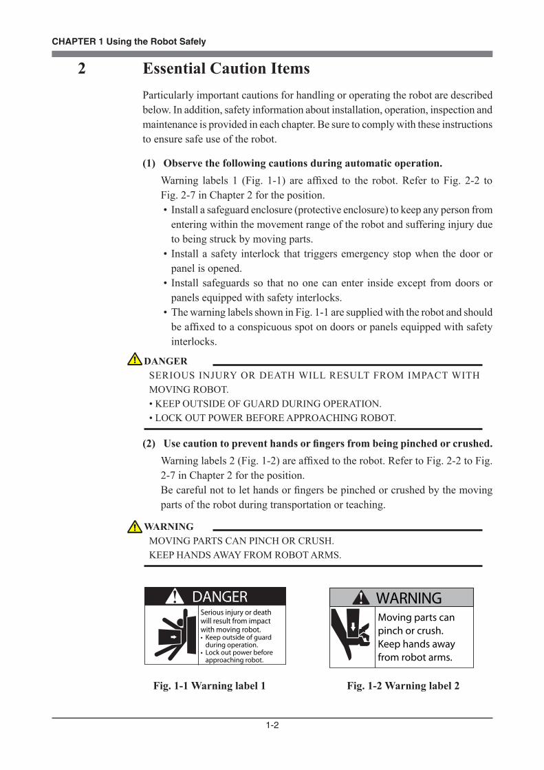
(1) Observe the following cautions during automatic operation.Warning labels 1 (Fig. 1-1) are affixed to the robot. Refer to Fig. 2-2 to Fig. 2-7 in Chapter 2 for the position.• Install a safeguard enclosure (protective enclosure) to keep any person from
entering within the movement range of the robot and suffering injury due to being struck by moving parts.
• Install a safety interlock that triggers emergency stop when the door or panel is opened.
• Install safeguards so that no one can enter inside except from doors or panels equipped with safety interlocks.
• The warning labels shown in Fig. 1-1 are supplied with the robot and should be affixed to a conspicuous spot on doors or panels equipped with safety interlocks.
(2) Use caution to prevent hands or fingers from being pinched or crushed.Warning labels 2 (Fig. 1-2) are affixed to the robot. Refer to Fig. 2-2 to Fig. 2-7 in Chapter 2 for the position.Be careful not to let hands or fingers be pinched or crushed by the moving parts of the robot during transportation or teaching.
DANGERSerious injury or death will result from impact with moving robot.• Keep outside of guard
during operation.• Lock out power before
approaching robot.
Moving parts can pinch or crush.Keep hands away from robot arms.
WARNING
Fig. 1-1 Warning label 1 Fig. 1-2 Warning label 2
DANGERSERIOUS INJURY OR DEATH WILL RESULT FROM IMPACT WITH MOVING ROBOT. • KEEP OUTSIDE OF GUARD DURING OPERATION. • LOCK OUT POWER BEFORE APPROACHING ROBOT.
WARNINGMOVING PARTS CAN PINCH OR CRUSH. KEEP HANDS AWAY FROM ROBOT ARMS.

1-3
CHAPTER 1 Using the Robot Safely
(3) Follow the instructions on warning labels and in this manual.Warning label 3 (Fig. 1-3) is affixed to the robot. Refer to Fig. 2-2 to Fig. 2-6 in Chapter 2 for the position.• Be sure to read the warning label and this manual carefully and make you
thoroughly understand the contents before attempting installation and operation of the robot.
• Before starting the robot operation, even after you have read through this manual, read again the corresponding procedures and cautions in this manual as well as descriptions in this chapter (Chapter 1, "Using the Robot Safely").
• Never install, adjust, inspect or service the robot in any manner that does not comply with the instructions in this manual.
Improper Installation or operation can result in serious injury or death. Read user's(owner's) manual and all warning labels before operation.
WARNING
Fig. 1-3 Warning label 3
(4) Do not remove the Z-axis upper-end mechanical stopperRemoving or moving the upper-end mechanical stopper attached to the Z-axis spline shaft of the R6YXG120 series can damage the Z-axis ball screw. Never remove or move it.
Fig. 1-4 Warning label 4
(5) Do not use the robot in environments containing inflammable gas, etc.
WARNINGIMPROPER INSTALLATION OR OPERATION CAN RESULT IN SERIOUS INJURY OR DEATH. READ USER’S MANUAL AND ALL WARNING LABELS BEFORE OPERATION.
CAUTIONDO NOT REMOVE THIS PART. DAMAGE TO THE BALL SCREW WILL RESULT.
WARNING• T H I S R O B O T WA S N O T D E S I G N E D F O R O P E R AT I O N I N ENVIRONMENTS WHERE INFLAMMABLE OR EXPLOSIVE SUBSTANCES ARE PRESENT. • DO NOT USE THE ROBOT IN ENVIRONMENTS CONTAINING INFLAMMABLE GAS, DUST OR LIQUIDS. EXPLOSIONS OR FIRE COULD OTHERWISE RESULT.

1-4
CHAPTER 1 Using the Robot Safely
(6) Do not use the robot in locations possibly subject to electromagnetic interference, etc.
(7) Use caution when releasing the Z-axis (vertical axis) brake.
(8) Provide safety measures for end effector (gripper, etc.).
(9) Be cautious of possible Z-axis movement when the controller is turned off or emergency stop is triggered. (2-axis robots with air-driven Z-axis)
WARNINGAV O I D U S I N G T H E R O B O T I N L O C AT I O N S S U B J E C T T O ELECTROMAGNETIC INTERFERENCE, ELECTROSTATIC DISCHARGE OR RADIO FREQUENCY INTERFERENCE. MALFUNCTION MAY OTHERWISE OCCUR.
WARNINGTHE Z-AXIS WILL SLIDE DOWN WHEN THE Z-AXIS BRAKE IS RELEASED, CAUSING A HAZARDOUS SITUATION. • PRESS THE EMERGENCY STOP BUTTON AND PROP UP THE Z-AXIS WITH A SUPPORT STAND BEFORE RELEASING THE BRAKE. • USE CAUTION NOT TO LET YOUR BODY GET CAUGHT BETWEEN THE Z-AXIS AND INSTALLATION BASE WHEN RELEASING THE BRAKE TO PERFORM DIRECT TEACH.
WARNING• END EFFECTORS MUST BE DESIGNED AND MANUFACTURED SO THAT THEY CAUSE NO HAZARDS (FOR EXAMPLE, LOOSENING OF WORKPIECE) EVEN IF POWER (ELECTRICITY, AIR PRESSURE, ETC.) IS SHUT OFF OR POWER FLUCTUATIONS OCCUR. • IF THERE IS A POSSIBLE DANGER THAT THE OBJECT GRIPPED BY THE END EFFECTOR MAY FLY OFF OR DROP, THEN PROVIDE APPROPRIATE SAFETY PROTECTION TAKING INTO ACCOUNT THE OBJECT SIZE, WEIGHT, TEMPERATURE AND CHEMICAL PROPERTIES.
WARNINGTHE Z-AXIS MOVES UP WHEN THE POWER TO THE CONTROLLER OR PLC IS TURNED OFF, THE PROGRAM IS RESET, EMERGENCY STOP IS TRIGGERED, OR AIR IS SUPPLIED TO THE SOLENOID VALVE FOR THE Z-AXIS AIR CYLINDER. • DO NOT LET HANDS OR FINGERS GET CAUGHT AND SQUEEZED BY MOVING PARTS OF THE Z-AXIS. • KEEP THE USUAL ROBOT POSITION IN MIND SO THAT THE Z-AXIS WILL NOT INTERFERE WITH OBSTACLES DURING RAISING OF THE Z-AXIS, EXCEPT IN CASE OF EMERGENCY STOP.

1-5
CHAPTER 1 Using the Robot Safely
(10) Use the following caution items when the Z-axis is interfering with peripheral equipment. (2-axis robots with air driven Z-axis)
(11) Use caution on Z-axis movement when air supply is stopped. (2-axis robots with air-driven Z-axis)
(12) Use the following caution items when disassembling or replacing the pneumatic equipment.
(13) Cautions for removing Z-axis brake or Z-axis motor
WARNINGWHEN THE Z-AXIS COMES TO A STOP DUE TO OBSTRUCTIONS FROM PERIPHERAL EQUIPMENT, THE Z-AXIS MAY MOVE SUDDENLY WHEN THE OBSTRUCTION IS REMOVED, CAUSING INJURY SUCH AS PINCHED OR CRUSHED HANDS. • TURN OFF THE CONTROLLER AND REDUCE THE AIR PRESSURE BEFORE ATTEMPTING TO REMOVE THE OBSTRUCTION. •BEFORE REDUCING THE AIR PRESSURE, PLACE A SUPPORT STAND UNDER THE Z-AXIS BECAUSE IT WILL DROP UNDER ITS OWN WEIGHT.
WARNINGTHE Z-AXIS MAY SUDDENLY DROP WHEN THE AIR PRESSURE TO THE Z-AXIS AIR CYLINDER SOLENOID VALVE IS REDUCED, CREATING A HAZARDOUS SITUATION. TURN OFF THE CONTROLLER AND PLACE A PROP OR SUPPORT UNDER THE Z-AXIS BEFORE CUTTING OFF THE AIR SUPPLY.
WARNINGAIR OR PARTS MAY FLY OUTWARDS IF PNEUMATIC EQUIPMENT IS DISASSEMBLED OR PARTS REPLACED WHILE AIR IS STILL SUPPLIED. • DO SERVICE WORK AFTER FIRST TURNING OFF THE CONTROLLER AND REDUCING THE AIR PRESSURE. • BEFORE REDUCING THE AIR PRESSURE, PLACE A SUPPORT STAND UNDER THE Z-AXIS (2-AXIS ROBOTS WITH AIR DRIVEN Z-AXIS) SINCE IT WILL DROP UNDER ITS OWN WEIGHT.
WARNINGTHE Z-AXIS WILL DROP WHEN THE Z-AXIS MOTOR IS REMOVED, POSSIBLY RESULTING IN INJURY. • TURN OFF THE CONTROLLER AND SET A SUPPORT STAND UNDER THE Z-AXIS BEFORE REMOVING THE MOTOR. • USE CAUTION NOT TO ALLOW HANDS OR BODY TO BE SQUEEZED OR CRUSHED BY MOVING PARTS ON THE Z-AXIS OR BETWEEN THE Z-AXIS AND THE INSTALLATION BASE.
1-6
CHAPTER 1 Using the Robot Safely
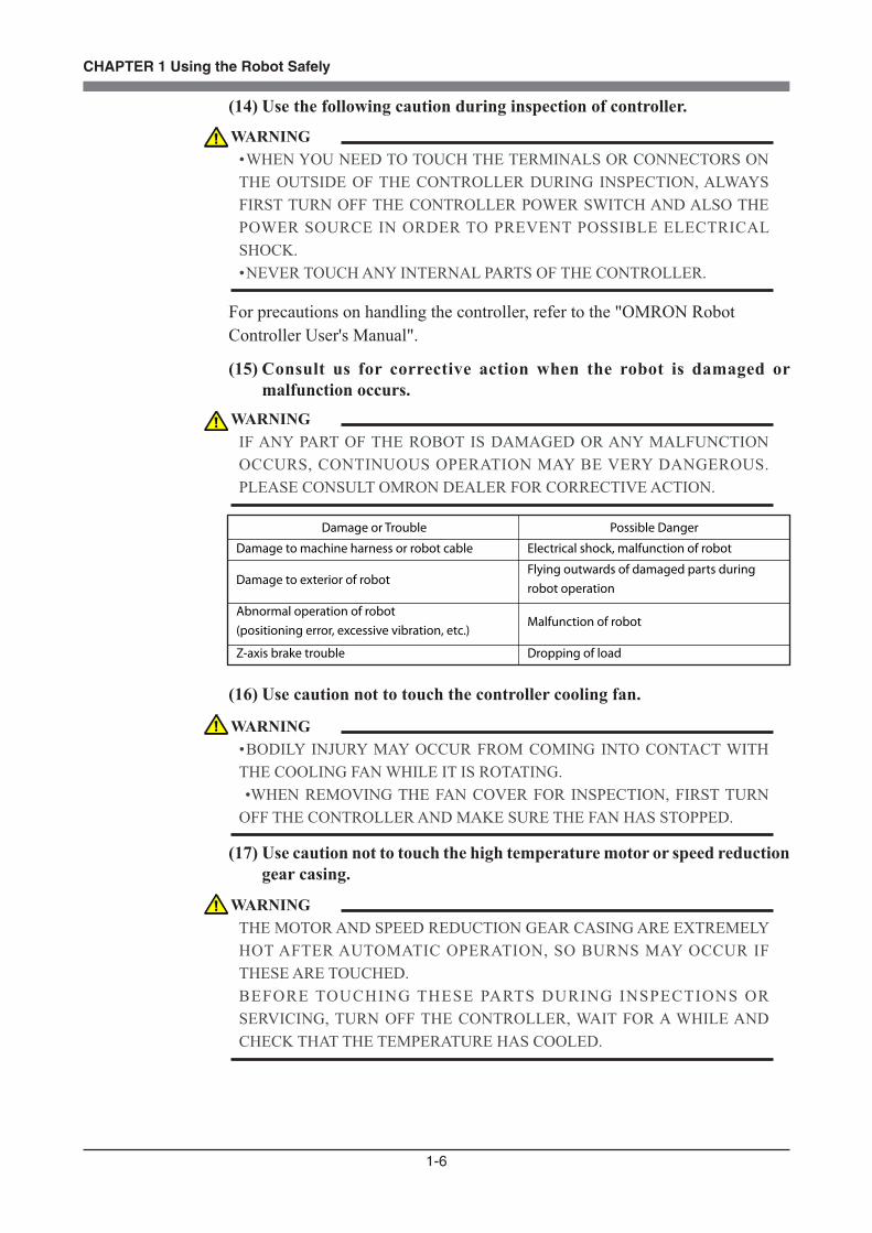
(14) Use the following caution during inspection of controller.
For precautions on handling the controller, refer to the "OMRON Robot Controller User's Manual".
(15) Consult us for corrective action when the robot is damaged or malfunction occurs.
Damage or Trouble Possible Danger
Damage to machine harness or robot cable Electrical shock, malfunction of robot
Damage to exterior of robotFlying outwards of damaged parts during robot operation
Abnormal operation of robot(positioning error, excessive vibration, etc.)
Malfunction of robot
Z-axis brake trouble Dropping of load
(16) Use caution not to touch the controller cooling fan.
(17) Use caution not to touch the high temperature motor or speed reduction gear casing.
WARNING• WHEN YOU NEED TO TOUCH THE TERMINALS OR CONNECTORS ON THE OUTSIDE OF THE CONTROLLER DURING INSPECTION, ALWAYS FIRST TURN OFF THE CONTROLLER POWER SWITCH AND ALSO THE POWER SOURCE IN ORDER TO PREVENT POSSIBLE ELECTRICAL SHOCK. • NEVER TOUCH ANY INTERNAL PARTS OF THE CONTROLLER.
WARNINGIF ANY PART OF THE ROBOT IS DAMAGED OR ANY MALFUNCTION OCCURS, CONTINUOUS OPERATION MAY BE VERY DANGEROUS. PLEASE CONSULT OMRON DEALER FOR CORRECTIVE ACTION.
WARNING• BODILY INJURY MAY OCCUR FROM COMING INTO CONTACT WITH THE COOLING FAN WHILE IT IS ROTATING. •WHEN REMOVING THE FAN COVER FOR INSPECTION, FIRST TURN OFF THE CONTROLLER AND MAKE SURE THE FAN HAS STOPPED.
WARNINGTHE MOTOR AND SPEED REDUCTION GEAR CASING ARE EXTREMELY HOT AFTER AUTOMATIC OPERATION, SO BURNS MAY OCCUR IF THESE ARE TOUCHED. BEFORE TOUCHING THESE PARTS DURING INSPECTIONS OR SERVICING, TURN OFF THE CONTROLLER, WAIT FOR A WHILE AND CHECK THAT THE TEMPERATURE HAS COOLED.

1-7
CHAPTER 1 Using the Robot Safely
(18) Do not remove, alter or stain the warning labels.
(19) Protective bonding
(20) Avoid fastening any cable or tube prepared by the user with the machine harness, user signal wires or air tubes of the robot.
(21) Do not use the robot in locations subject to strong vibrations.
(22) Be sure to make correct parameter settings.
WARNINGIF WARNING LABELS ARE REMOVED OR DIFFICULT TO SEE, NECESSARY CAUTIONS MAY NOT BE TAKEN, RESULTING IN AN ACCIDENT. •DO NOT REMOVE, ALTER OR STAIN THE WARNING LABELS ON THE ROBOT. • DO NOT ALLOW THE WARNING LABELS TO BE HIDDEN BY THE DEVICE INSTALLED TO THE ROBOT BY THE USER. • PROVIDE PROPER LIGHTING SO THAT THE SYMBOLS AND INSTRUCTIONS ON THE WARNING LABELS CAN BE CLEARLY SEEN EVEN FROM THE OUTSIDE OF SAFEGUARDS.
WARNINGBE SURE TO GROUND THE ROBOT AND CONTROLLER TO PREVENT ELECTRICAL SHOCK.
CAUTIONTHE ROBOT MUST BE OPERATED WITH CORRECT TOLERABLE MOMENT OF INERTIA AND ACCELERATION COEFFICIENTS ACCORDING TO THE MANIPULATOR TIP MASS AND MOMENT OF INERTIA. IF THIS IS NOT OBSERVED, PREMATURE END TO THE LIFE OF THE DRIVE UNITS, DAMAGE TO THE ROBOT PARTS OR RESIDUAL VIBRATION DURING POSITIONING MAY RESULT.
WARNINGDO NOT UTILIZE THE MACHINE HARNESS, USER SIGNAL WIRES OR AIR TUBES OF THE ROBOT TO FASTEN ANY CABLE OR TUBE PREPARED BY THE USER, AS THIS MAY BREAK THE ROBOT HARNESS WIRES OR USER SIGNAL WIRES CAUSING MALFUNCTION OF THE ROBOT. THIS WILL ALSO RESULT IN POOR POSITIONING ACCURACY.
WARNINGDO NOT OPERATE THE ROBOT IN LOCATIONS SUBJECT TO STRONG VIBRATIONS. THE ROBOT INSTALLATION BOLTS MIGHT WORK LOOSE AND THE ROBOT TOPPLE OVER. THE BOLTS ON THE ROBOT BODY ITSELF MIGHT ALSO LOOSEN, CAUSING PARTS TO FALL OFF, ETC.

1-8
CHAPTER 1 Using the Robot Safely
(23) Do not apply excessive force to each section.
AxisR6YXG120, R6YXG150, R6YXG180, R6YXG220, R6YXC180, R6YXC220
X-axis
Y-axis
R-axis
Tolerable radial load
275N (28.1kgf)
150N (15.3kgf)
150N (15.3kgf)
Tolerable thrust load
900N (91.8kgf)
600N (61.2kgf)
600N (61.2kgf)
Tolerable moment load Tolerable torque
6.0Nm (61.2kgfcm)
3.3Nm (33.7kgfcm)
3.3Nm (33.7kgfcm)
9.0Nm (91.8kgfcm)
4.0Nm (40.8kgfcm)
2.2Nm (22.4kgfcm)
(24) Check the machine reference value when the arm struck against the mechanical stopper.
(25) Use caution not to apply excessive force to the machine harness, user signal cables and air tubes.
(26) Caution when turning off the robot controller
CAUTIONTHE TINY SERIES (R6YXG120, R6YXG150, R6YXG180, R6YXG220) AND XC SERIES (R6YXC180, R6YXC220) ARE DESIGNED TO BE COMPACT, SO THE JOINTS COULD BE DAMAGED IF EXCESSIVE FORCE IS APPLIED, FOR EXAMPLE, DURING INSTALLATION OF AN END EFFECTOR. MAKE SURE THAT EXCESSIVE FORCE IS NOT APPLIED TO THE JOINTS.
CAUTIONWHEN THE ARM MOVES AT HIGH SPEED AND STRIKES AGAINST A MECHANICAL STOPPER VIOLENTLY, THE MACHINE REFERENCE VALUE MAY CHANGE. IF THIS HAS HAPPENED, CHECK THE MACHINE REFERENCE VALUE. ALSO CHECK THE MECHANICAL STOPPER FOR ANY DAMAGE AND THE ORIGIN POSITION FOR SHIFT. IF THE MACHINE REFERENCE VALUE IS OUTSIDE THE RECOMMENDED RANGE, ADJUST THE MACHINE REFERENCE. IN THIS CASE, RE-TEACHING MAY BE REQUIRED IF THE ORIGIN POSITION HAS SHIFTED.
CAUTIONA POSITIONING ERROR MAY OCCUR IF EXCESSIVE FORCE IS APPLIED TO THE MACHINE HARNESS, USER SIGNAL CABLES OR AIR TUBES. A POSITIONING ERROR MAY ALSO OCCUR IF THE MACHINE HARNESS, USER SIGNAL CABLES OR AIR TUBES HAVE DETERIORATED DUE TO IMPROPER INSTALLATION ENVIRONMENT.
CAUTIONTHE XY ARM POSITIONS MIGHT MOVE SLIGHTLY DUE TO THE HARNESS REACTION FORCE WHEN THE POWER TO THE ROBOT CONTROLLER IS TURNED OFF, MAKING IT DIFFICULT TO BACK UP THE CORRECT POSITION DATA. TO AVOID THIS, BEFORE TURNING OFF THE POWER TO THE ROBOT CONTROLLER, PRESS THE EMERGENCY STOP BUTTON AND CHECK THAT THE ROBOT ARMS HAVE COMPLETELY STOPPED.
1-9
CHAPTER 1 Using the Robot Safely
(27) Take the following precautions when transporting the robot.
(28) If the X, Y or R axis rotation angle is small
(29) When attaching a user wire or tube to a movable cable
(30) Follow the specified procedures when installing, adjusting or inspecting the robot.
(31) Do not attempt any repair, parts replacement and modification.
CAUTIONIF THE X, Y OR R AXIS ROTATION ANGLE IS SMALLER THAN 5° SO THAT IT ALWAYS MOVES IN THE SAME POSITION, AN OIL FILM IS DIFFICULT TO BE FORMED ON THE JOINT SUPPORT BEARING, POSSIBLY LEADING TO DAMAGE TO THE BEARING. IN THIS TYPE OF OPERATION, ADD A MOVEMENT SO THAT THE JOINT MOVES THROUGH 90° OR MORE, ABOUT 5 TIMES A DAY.
CAUTIONIF THE ROBOT IS TRANSPORTED LONG DISTANCES BY TRUCK WHILE MOUNTED ON AN INSTALLATION BASE OR PACKED IN A CASE OTHER THAN THE DEDICATED CARTON BOX IN WHICH THE ROBOT WAS SHIPPED, THE BOLTS INSTALLING THE ROBOT OR THE BOLTS ON THE ROBOT BODY ITSELF MIGHT COME LOOSE DUE TO VIBRATION. THE ROBOT MIGHT THEN TOPPLE OVER OR THE PARTS FALL OFF. WHEN TRANSPORTING THE ROBOT LONG DISTANCES, USE THE DEDICATED CASE IN WHICH THE ROBOT WAS SHIPPED FROM OUR FACTORY.
CAUTIONDO NOT ATTACH ANY WIRE OR TUBE TO THE SELF-SUPPORTING CABLE. DOING SO MIGHT DEGRADE THE POSITIONING ACCURACY. IF ATTACHING A WIRE OR TUBE, MAKE USE OF THE AIR TUBES. FOR DETAILS, REFER TO “10 WHEN ATTACHING A NEW USER WIRE OR TUBE” IN CHAPTER 3.
WARNINGALWAYS FOLLOW THE SPECIFIED PROCEDURES WHEN INSTALLING, ADJUSTING OR INSPECTING THE ROBOT. NEVER ATTEMPT ANY PROCEDURE NOT DESCRIBED IN THIS MANUAL.
WARNINGDO NOT ATTEMPT ANY REPAIR, PARTS REPLACEMENT AND MODIFICATION UNLESS DESCRIBED IN THIS MANUAL. THESE WORKS REQUIRE TECHNICAL KNOWLEDGE AND SKILL, AND MAY ALSO INVOLVE WORK HAZARDS.
1-10
CHAPTER 1 Using the Robot Safely
(32) Precautions when disposing of the robotWhen disposing of the robot, handle it as industrial waste.
(33) Location for installing the controller and the programming boxThe robot controller and programming box should be installed at a location that is outside the robot movement range yet where it is easy to operate and view the robot performing tasks.
(34) Protect electrical wiring and hydraulic/pneumatic hoses as needed.Install a cover or similar item to protect the electrical wiring and hydraulic/pneumatic hoses from possible damage.
(35) Install an operation status light.Install an operation status light (signal light tower, etc.) at an easy-to-see position so the operator will know whether the robot is merely stopped or is in emergency-error stop.
(36) Clean work tools, etc.Work tools such as welding guns and paint nozzles which are mounted in the robot arm will preferably be cleaned automatically.
(37) Provide adequate lighting.Make sure to provide enough lighting to ensure safety during work.
(38) Draw up "work instructions" and makes sure the operator learns them well.Decide on "work instructions" for the following items in cases where personnel must work within the robot movement range to perform teaching, maintenance or inspection. Make sure the workers know these "work instructions" well.(1) Robot operating procedures needed for tasks such as startup procedures
and handling switches(2) Robot speeds used during tasks such as teaching(3) Methods for workers to signal each other when two or more workers
perform tasks(4) Steps that the worker should take when a problem or emergency occurs(5) Steps to take after the robot has come to a stop when the emergency stop
device was triggered, including checks for cancelling the problem or error state and safety checks in order to restart the robot.
(6) In cases other than above, the following actions should be taken as needed to prevent hazardous situations due to sudden or unexpected robot operation or faulty robot operation, as listed below.1. Show a display on the operator panel2. Ensure the safety of workers performing tasks within the robot
movement range

1-11
CHAPTER 1 Using the Robot Safely
3. Clearly specify position and posture during work Position and posture where worker can constantly check robot movements
and immediately move to avoid trouble if an error/problem occurs4. Install noise prevention measures5. Use methods for signaling operators of related equipment6. Use methods to decide that an error has occurred and identify the type
of errorImplement the "work instructions" according to the type of robot, installation location, and type of work task.When drawing up the "work instructions", make an effort to include opinions from the workers involved, equipment manufacture's technicians, and workplace safety consultants, etc.
(39) Display a sign on operation panel during workDisplay an easy to understand sign or message on the programming box and operation panel during the job task, to prevent anyone other than the operators for that job task from mistakenly operating a start or selector switch. If needed, take other measures such as locking the cover on the operation panel.
(40) Make daily and periodic inspections.(1) Always make sure that daily and periodic inspections are performed, and
make a pre-work check to ensure there are no problems with the robot or related equipment. If a problem or abnormality is found, then promptly repair it or take other measures as necessary.
(2) When you make periodic inspections or repairs, make a record and store it for at least 3 years.

1-12
CHAPTER 1 Using the Robot Safely
3 Industrial Robot Operating and Maintenance PersonnelOperators or persons who handle the robot such as for teaching, programming, movement check, inspection, adjustment, and repair must receive appropriate training and also have the skills needed to perform the job correctly and safely. They must read the user's manual carefully to understand its contents before at-tempting the robot operation.
Tasks related to industrial robots (teaching, programming, movement check, inspection, adjustment, repair, etc.) must be performed by qualified persons who meet requirements established by local regulations and safety standards for industrial robots.
1-13
CHAPTER 1 Using the Robot Safely
4 Robot Safety Functions(1) Overload detection
This function detects an overload applied to the motor and shuts off the servo power. If an overload error occurs, take the following measures.1. Insert a timer in the program. 2. Reduce the acceleration coefficient.
(2) Overheat detectionThis function detects an abnormal temperature rise in the driver inside the controller and shuts off the servo power. If an overheat error occurs, take the following measures.1. Insert a timer in the program. 2. Reduce the acceleration coefficient.
(3) Soft limitsSoft limits can be set on each axis to limit the working envelope in manual operation after return-to-origin and during automatic operation.Note: The working envelope is the area limited by soft limits.
(4) Mechanical stoppersIf the servo power is suddenly shut off during high-speed operation by emergency stop or safety functions, these mechanical stoppers prevent the axis from exceeding the movement range. On the X-axis, Y-axis arm, mechanical stoppers are fixed at %ÆTh ends of the maximum movement range.The Z-axis has a mechanical stopper at the upper end and lower end.No mechanical stopper is provided on the R-axis.Note: The movement range is the area limited by mechanical stoppers.
(5) Z-axis (vertical axis) brakeAn electromagnetic brake is installed on the Z-axis to prevent the Z-axis from sliding down when servo power is turned off. This brake is working when the controller is off or the Z-axis servo power is off even when the controller is on. The Z-axis brake can be released by means of the programming box or by a command in the program when the controller is on.
WARNINGAXIS MOVEMENT WILL NOT STOP IMMEDIATELY AFTER THE SERVO POWER SUPPLY IS SHUT OFF BY EMERGENCY STOP OR OTHER SAFETY FUNCTIONS.
WARNINGSOFT LIMITS MUST BE SET WITHIN THE MOVEMENT RANGE (MECHANICAL STOPPER). IF THE SOFT LIMIT IS SET OUTSIDE THE MOVEMENT RANGE, THE ROBOT AXIS MAY COLLIDE WITH THE MECHANICAL STOPPER AT HIGH SPEED, CAUSING THE OBJECT GRIPPED BY THE END EFFECTOR TO FLY OR DROP AND THE ROBOT TO MALFUNCTION.

1-14
CHAPTER 1 Using the Robot Safely
5 Safety Measures for the SystemSince the robot is commonly used in conjunction with an automated system, dangerous situations are more likely to occur from the automated system than from the robot itself. Accordingly, appropriate safety measures must be taken on the part of the system manufacturer according to the individual system. The system manufacturer should provide a proper user's manual for safe, correct operation and servicing of the system.
WARNINGTHE Z-AXIS WILL SLIDE DOWN WHEN THE Z-AXIS BRAKE IS RELEASED, CREATING A HAZARDOUS SITUATION. • PRESS THE EMERGENCY STOP BUTTON AND PROP THE Z-AXIS WITH A SUPPORT STAND BEFORE RELEASING THE BRAKE. • USE CAUTION NOT TO LET YOUR BODY GET CAUGHT BETWEEN THE Z-AXIS AND INSTALLATION BASE WHEN RELEASING THE BRAKE TO PERFORM DIRECT TEACH.
1-15
CHAPTER 1 Using the Robot Safely
6 Trial OperationAfter making installations, adjustments, inspections, maintenance or repairs to the robot, make a trial run using the following procedures.
(1) If a safeguard enclosure has not yet been provided right after installation of the robot, rope off or chain off around the movement area of the manipulator in place of the safeguard enclosure, and observe the following points.1. Use sturdy, stable posts which will not fall over easily. 2. The rope or chain should be easily visible by everyone around the robot.3. Place a sign to keep the operator or other personnel from entering the
movement range of the manipulator. (2) Check the following points before turning on the controller.
1. Is the robot securely and correctly installed?2. Are the electrical connections to the robot correct?3. Are items such as air pressure correctly supplied?4. Is the robot correctly connected to peripheral equipment?5. Have safety measures (safeguard enclosure, etc.) been taken?6. Does the installation environment meet the specified standards?
(3) After the controller is turned on, check the following points from outside the safeguard enclosure.1. Does the robot start and stop as intended? Can the operation mode be
selected correctly?2. Does each axis move as intended within the soft limits?3. Does the end effector move as intended?4. Are the signal transmissions to the end effector and peripheral equipment
correct?5. Does emergency stop work?6. Are the teaching and playback functions normal?7. Are the safeguard enclosure and interlock working as intended?8. Does the robot move correctly during automatic operation?

1-16
CHAPTER 1 Using the Robot Safely
7 Work Within the Safeguard Enclosure(1) When work is required inside the safeguard enclosure, always turn off the
controller and place a sign indicating that the robot is being adjusted or serviced in order to keep any other person from touching the controller switch or operation panel, except for the following cases.1) Adjusting the Z-axis machine reference (See Section 3-4-1-5 in Chapter
4.)2) Setting the Soft Limits (See Section 4 in Chapter 4.)3) Setting the Standard Coordinates (See Section 5 in Chapter 4.)4) Teaching
For items 1) to 3), follow the precautions and procedure for each section. To perform item 4), refer to the description in (2) below.
(2) TeachingWhen performing teaching within the safeguard enclosure, comply with the instructions listed below. 1) Check or perform the following points from outside the safeguard
enclosure.1. Make sure that no hazards are present within the safeguard enclosure
by a visual check.2. Check that the programming box (PB) operates correctly.3. Check that no failures are found in the robot.4. Check that emergency stop works correctly.5. Select teaching mode and prohibit automatic operation.
2) Never enter the movement range of the manipulator while within the safeguard enclosure.
1-17
CHAPTER 1 Using the Robot Safely
8 Automatic OperationAutomatic operation described here includes all operations in AUTO mode.
(1) Check the following before starting automatic operation.1. No one is within the safeguard enclosure.2. The programming box and tools are in their specified locations.3. The alarm or error lamps on the robot and peripheral equipment do not
flash.4. The safeguard enclosure is securely installed with safety interlocks
actuated.(2) Observe the following during automatic operation or in cases where an error
occurs.1) After automatic operation has started, check the operation status and
warning lamp to ensure that the robot is in automatic operation.2) Never enter the safeguard enclosure during automatic operation.3) If an error occurs in the robot or peripheral equipment, observe the
following procedure before entering the safeguard enclosure.1. Press the emergency stop button to set the robot to emergency stop.2. Place a sign on the start switch, indicating that the robot is being
inspected in order to keep any other person from touching the start switch and restarting the robot.

1-18
CHAPTER 1 Using the Robot Safely
9 WarrantyThe OMRON robot and/or related product you have purchased are warranted against the defects or malfunctions as described below.
Warranty description : If a failure or breakdown occurs due to defects in materials or workmanship in the genuine parts constituting this OMRON robot and/or related product within the warranty period, then OMRON shall supply free of charge the necessary replacement/repair parts.
Warranty Period : The warranty period ends 24 months after the date of manufacturing as shown on the products.
Exceptions to the Warranty : This warranty will not apply in the following cases:
(1) Fatigue arising due to the passage of time, natural wear and tear occurring during
operation (natural fading of painted or plated surfaces, deterioration of parts subject to wear, etc.)
(2) Minor natural phenomena that do not affect the capabilities of the robot and/or related product (noise from computers, motors, etc.).
(3) Programs, point data and other internal data that were changed or created by the user.
Failures resulting from the following causes are not covered by warranty.
1) Damage due to earthquakes, storms, floods, thunderbolt, fire or any other natural or man-made disasters.
2) Troubles caused by procedures prohibited in this manual.3) Modifications to the robot and/or related product not approved by OMRON
or OMRON sales representatives.4) Use of any other than genuine parts and specified grease and lubricants.5) Incorrect or inadequate maintenance and inspection.6) Repairs by other than authorized dealers.
1-19
CHAPTER 1 Using the Robot Safely
WARRANTY OMRON’s exclusive warranty is that the products are free from defects in materials and
workmanship for a period of one year (or other period if specified) from date of sale by OMRON.
OMRON MAKES NO WARRANTY OR REPRESENTATION, EXPRESS OR IMPLIED, R E G A R D I N G N O N I N F R I N G E M E N T, M E R C H A N TA B I L I T Y, O R F I T N E S S F O R PARTICULAR PURPOSE OF THE PRODUCTS. ANY BUYER OR USER ACKNOWLEDGES THAT THE BUYER OR USER ALONE HAS DETERMINED THAT THE PRODUCTS WILL SUITABLY MEET THE REQUIREMENTS OF THEIR INTENDED USE. OMRON DISCLAIMS ALL OTHER WARRANTIES, EXPRESS OR IMPLIED.
LIMITATIONS OF LIABILITY O M R O N S H A L L N O T B E R E S P O N S I B L E F O R S P E C I A L , I N D I R E C T, O R
CONSEQUENTIAL DAMAGES, LOSS OF PROFITS OR COMMERCIAL LOSS IN ANY WAY CONNECTED WITH THE PRODUCTS, WHETHER SUCH CLAIM IS BASED ON CONTRACT, WARRANTY, NEGLIGENCE, OR STRICT LIABILITY.
In no event shall the responsibility of OMRON for any act exceed the individual price of the product on which liability is asserted.
IN NO EVENT SHALL OMRON BE RESPONSIBLE FOR WARRANTY, REPAIR, OR OTHER CLAIMS REGARDING THE PRODUCTS UNLESS OMRON’S ANALYSIS C O N F I R M S T H AT T H E P R O D U C T S W E R E P R O P E R LY H A N D L E D , S TO R E D , INSTALLED, AND MAINTAINED AND NOT SUBJECT TO CONTAMINATION, ABUSE, MISUSE, OR INAPPROPRIATE MODIFICATION OR REPAIR.


CHAPTER 2
Functions
1 Robot Manipulator ................................................................................................2-1
2 Robot Controller ...................................................................................................2-7
3 Robot Initialization Number List ..........................................................................2-8
4 Parameters for Clean Room Models R6YXC120, R6YXC150 ...........................2-9
5 Tip Weight Parameter Setting and WEIGHT Statement in Programs ................2-10


2-1
CHAPTER 2 Functions
1 Robot ManipulatorThe X series robots are available in 4-axis models having an X/Y-axis arm (equiva-lent to human arm) and a Z/R-axis (equivalent to human wrist). With these 4 axes, the X series robots can move as shown in Fig. 2-1. By attaching different types of end effector (gripper) to the end of the arm, a wide range of tasks can be performed with high precision at high speeds.The (+) and (-) signs show the direction of axis movement when the jog keys on the programming box are pressed (standard setting at the factory). Fig. 2-2 to Fig. 2-7 on the subsequent pages show part names and functions of each robot model.
Y-axis arm
Y-axis
(–)
X-axis arm
(+)
Z-axis
X-axis
(–)
(–)
(+)
(+)R-axis
(–)
(+)
Fig. 2-1 Manipulator movement
2-2
CHAPTER 2 Functions
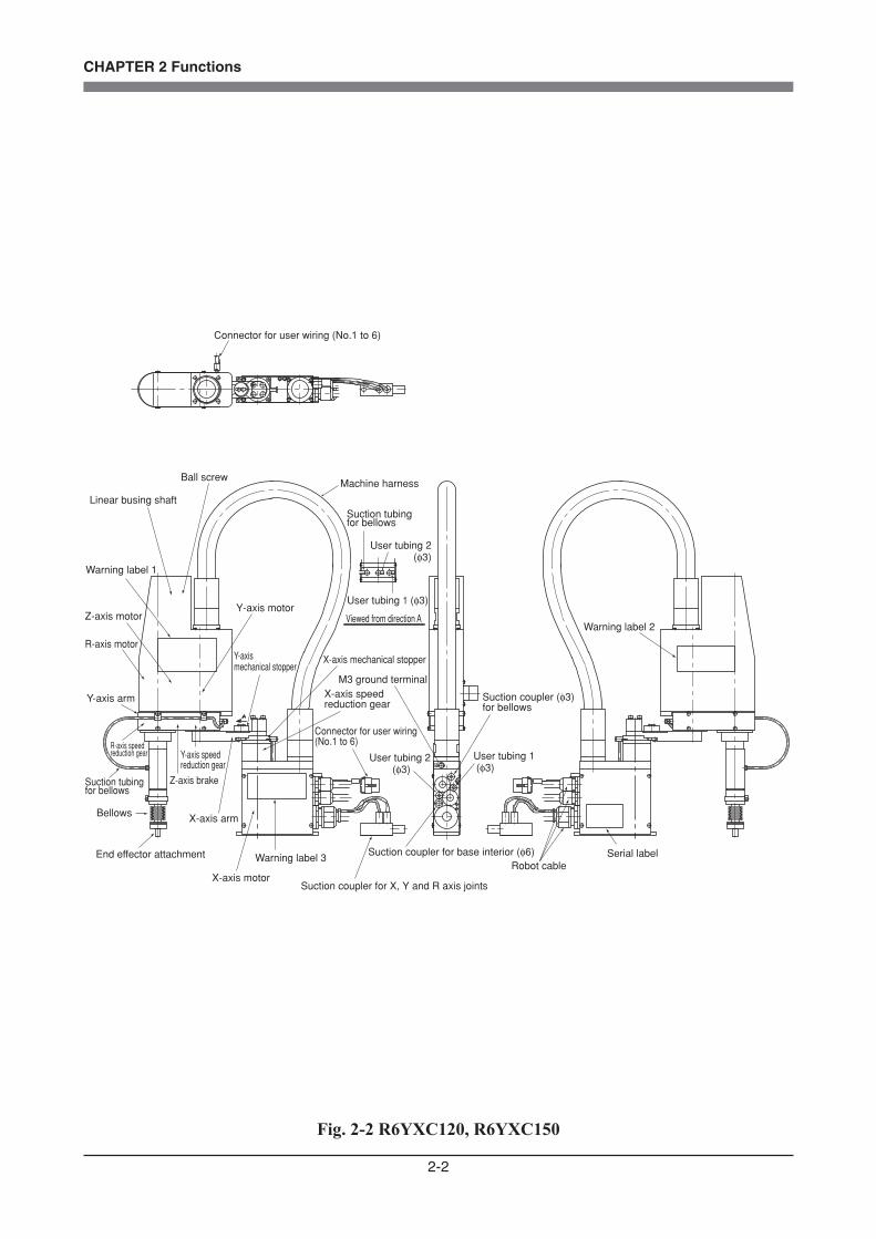
Serial label
Connector for user wiring (No.1 to 6)
Warning label 2
Robot cable
User tubing 1 (φ3)
Suction coupler for base interior (φ6)
User tubing 2 (φ3)
M3 ground terminal
User tubing 2 (φ3)
User tubing 1 (φ3)
Machine harness
Suction coupler for X, Y and R axis joints
Connector for user wiring (No.1 to 6)
Warning label 3
X-axis motor
X-axis speed reduction gear
X-axis mechanical stopperY-axis mechanical stopper
End effector attachment
Bellows
Y-axis speed reduction gear
Z-axis brake
X-axis arm
R-axis speed reduction gear
Linear busing shaft
Ball screw
Y-axis arm
Z-axis motor
Warning label 1
Suction tubing for bellows
Y-axis motor
R-axis motor
Suction coupler (φ3) for bellows
Suction tubing for bellows
Viewed from direction A
Fig. 2-2 R6YXC120, R6YXC150
2-3
CHAPTER 2 Functions
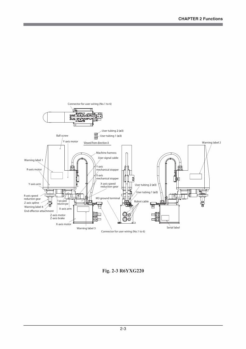
A
Serial label
Connector for user wiring (No.1 to 6)
Warning label 1
Robot cable
User tubing 1 (ø3)
User tubing 1 (ø3)
User tubing 2 (ø3)
Machine harness
Connector for user wiring (No.1 to 6)Warning label 3
X-axis speed reduction gear
X-axis mechanical stopper
Y-axis mechanical stopper
End effector attachment
Y-axis speed reduction gear
X-axis arm
R-axis speed reduction gearZ-axis spline
Y-axis arm
Z-axis motorZ-axis brake
Ball screw
Y-axis motor
R-axis motor
X-axis motor
User tubing 2 (ø3)
Warning label 2
M3 ground terminal
User signal cable
Viewed from direction A
Warning label 4
Fig. 2-3 R6YXG220

2-4
CHAPTER 2 Functions
A
Serial label
Connector for user wiring (No.1 to 8)
Warning label 1
Robot cable
User tubing 1 (ø4)
User tubing 1 (ø4)User tubing 2 (ø4)
Machine harness
Connector for user wiring (No.1 to 8)
Warning label 3
X-axis speed reduction gear
X-axis mechanical stopper
Y-axis mechanical stopper
End effector attachment
Y-axis speed reduction gear
X-axis armR-axis speed reduction gear
Z-axis spline
Y-axis arm
Z-axis brake
Ball screw
R-axis motor
X-axis motor
User tubing 2 (ø4)
Warning label 2
M3 ground terminal
User signal cable
Viewed from direction A
Warning label 4
Z-axis motor
Y-axis motor
Fig. 2-4 R6YXG120

2-5
CHAPTER 2 Functions
A
Serial label
Connector for user wiring (No.1 to 8)
Warning label 1
Robot cable
User tubing 1 (ø4)
User tubing 1 (ø4)User tubing 2 (ø4)
Machine harness
Connector for user wiring (No.1 to 8)
Warning label 3
X-axis speed reduction gear
X-axis mechanical stopper
Y-axis mechanical stopperEnd effector
attachment
Y-axis speed reduction gear
X-axis armR-axis speed reduction gear
Z-axis spline
Z-axis brake
Ball screw
R-axis motor
X-axis motor
User tubing 2 (ø4)
Warning label 2
M3 ground terminal
User signal cable
Viewed from direction A
Warning label 4
Z-axis motor
Y-axis motor
Fig. 2-5 R6YXG150, R6YXG180

2-6
CHAPTER 2 Functions
Serial label
Connector for user wiring (No.1 to 8)
Warning label 1
Robot cable
Machine harness
Connector for user wiring (No.1 to 8)
Warning label 3
X-axis speed reduction gear
X-axis mechanical stopper
End effector attachment
Y-axis speed reduction gear
X-axis arm
R-axis speed reduction gear
Y-axis arm
Z-axis splineBellows
Z-axis motorZ-axis brake
Ball screw
Y-axis motor
R-axis motor
X-axis motor
Warning label 2
M3 ground terminal
Y-axis mechanical stopper
Suction tubing (φ8) for cover interior
Suction tubing (φ6) for X, Y and R axis joints
User tubing 1 (φ3) User tubing 2 (φ3)
User tubing 2 (φ3)User tubing 1 (φ3)
Fig. 2-6 R6YXC180, R6YXC220
2-7
CHAPTER 2 Functions
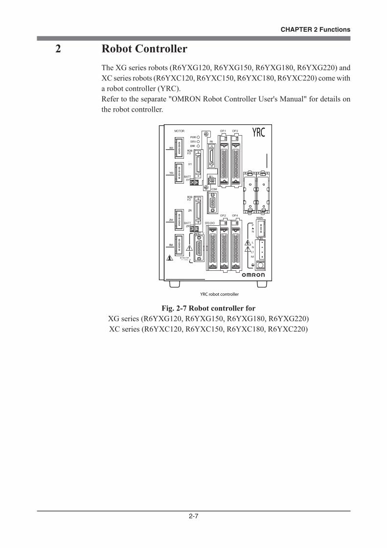
2 Robot ControllerThe XG series robots (R6YXG120, R6YXG150, R6YXG180, R6YXG220) and XC series robots (R6YXC120, R6YXC150, R6YXC180, R6YXC220) come with a robot controller (YRC).Refer to the separate "OMRON Robot Controller User's Manual" for details on the robot controller.
PB
MOTOR
XM
YM
ZM
RM
PWRSRV
SAFET Y
COM
STD.DIO
ROBI/O
ZR
OP.1 OP.3
OP.2 OP.4RGEN
ACIN
N
P
N1
L1
L
N
SEL
BATTZR
XYBATT
ROB
XY
I/O
13 14EXT.E-S TOP
ERR
YRC
YRC robot controller
OMRON
Fig. 2-7 Robot controller for XG series (R6YXG120, R6YXG150, R6YXG180, R6YXG220) XC series (R6YXC120, R6YXC150, R6YXC180, R6YXC220)
2-8
CHAPTER 2 Functions
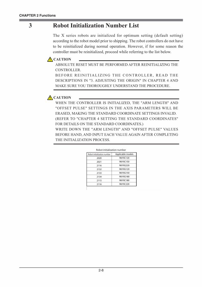
3 Robot Initialization Number ListThe X series robots are initialized for optimum setting (default setting) according to the robot model prior to shipping. The robot controllers do not have to be reinitialized during normal operation. However, if for some reason the controller must be reinitialized, proceed while referring to the list below.
Robot initialization number
2020
2021
2116
2132
2133
2134
2115
2116
Applicable models
R6YXC120
R6YXC150
R6YXG220
R6YXG120
R6YXG150
R6YXG180
R6YXC180
R6YXC220
Robot initialization number
CAUTIONABSOLUTE RESET MUST BE PERFORMED AFTER REINITIALIZING THE CONTROLLER. B E F O R E R E I N I T I A L I Z I N G T H E C O N T R O L L E R , R E A D T H E DESCRIPTIONS IN "3. ADJUSTING THE ORIGIN" IN CHAPTER 4 AND MAKE SURE YOU THOROUGHLY UNDERSTAND THE PROCEDURE.
CAUTIONWHEN THE CONTROLLER IS INITIALIZED, THE "ARM LENGTH" AND "OFFSET PULSE" SETTINGS IN THE AXIS PARAMETERS WILL BE ERASED, MAKING THE STANDARD COORDINATE SETTINGS INVALID. (REFER TO "CHAPTER 4 SETTING THE STANDARD COORDINATES" FOR DETAILS ON THE STANDARD COORDINATES.) WRITE DOWN THE "ARM LENGTH" AND "OFFSET PULSE" VALUES BEFORE HAND, AND INPUT EACH VALUE AGAIN AFTER COMPLETING THE INITIALIZATION PROCESS.

2-9
CHAPTER 2 Functions
4 Parameters for Clean Room Models R6YXC120, R6YXC150Part of robot parameters on clean room models has been changed to maintain the degree of cleanliness and the Z-axis bellows durability.Along with this robot parameter change shown below, you must take the following precautions.
To purchasers of this robotAt this time our sincere thanks for your purchase of our robot.Since this robot is custom designed and manufactured, a robot parameter has been changed from the standard specifications. Please keep this sheet carefully along with the user's manual.Check the following points before using the robot.
Precautions during useAlways make a backup of robot parameters.Initializing the parameters deletes previous parameter settings. If necessary, load the backup parameters.
Parameter changesThe following parameter has been changed. Blank portions indicate standard specifications are used.
PRM37M1 M3M2
1500M3
Max. motor rotation
ChangesParameter No. Name
Axis settings

2-10
CHAPTER 2 Functions
5 Tip Weight Parameter Setting and WEIGHT Statement in ProgramsThe tip weight parameter setting and WEIGHT statement in programs for the R6YXG120 and R6YXC180 series differ from those for other robots. Set the tip weight parameter and WEIGHT statement to match the actual load as shown in the table below.If this is not observed, drive units will be damaged or the service life will shorten.
0
0.1
0.2
0.3
0.4
0.5
0.6
0.7
0.8
0.9
1.0
0
1
2
3
4
5
6
7
8
9
10
WEIGHT 0
WEIGHT 1
WEIGHT 2
WEIGHT 3
WEIGHT 4
WEIGHT 5
WEIGHT 6
WEIGHT 7
WEIGHT 8
WEIGHT 9
WEIGHT 10
Actual load [kg] Tip weight parameter [×0.1kg] WEIGHT

CHAPTER 3
Installation
1 Robot Installation Conditions ...............................................................................3-11-1 Installation environments ....................................................................................................3-11-2 Installation base ...................................................................................................................3-3
2 Installation ............................................................................................................3-52-1 Unpacking ............................................................................................................................3-52-2 Checking the product ...........................................................................................................3-62-3 Moving the robot .................................................................................................................3-72-4 Installing the robot ...............................................................................................................3-8
3 Protective Bonding ...............................................................................................3-9
4 Robot Cable Connection .....................................................................................3-11
5 User Wiring and User Tubing .............................................................................3-13
6 Connecting a Suction Hose (R6YXC120, R6YXC150, R6YXC180, R6YXC220) .......3-17
7 Attaching the End Effector .................................................................................3-187-1 R-axis tolerable moment of inertia and acceleration coefficient .......................................3-18
7-1-1 Acceleration coefficient vs. moment of inertia (R6YXC120) ............................................ 3-20
7-1-2 Acceleration coefficient vs. moment of inertia (R6YXC150) ............................................ 3-22
7-1-3 Acceleration coefficient vs. moment of inertia (R6YXC180, R6YXC220, R6YXG220) . 3-24
7-1-4 Acceleration coefficient vs. moment of inertia (R6YXG120)............................................ 3-25
7-1-5 Acceleration coefficient vs. moment of inertia (R6YXG150)............................................ 3-26
7-1-6 Acceleration coefficient vs. moment of inertia (R6YXG180)............................................ 3-27
7-2 Equation for moment of inertia calculation .......................................................................3-287-3 Example of moment of inertia calculation ........................................................................3-317-4 Attaching the end effector .................................................................................................3-337-5 Gripping force of end effector ...........................................................................................3-36
8 Working Envelope and Mechanical Stopper Positions for Maximum Working Envelope .............................................................................3-37
9 Stopping Time and Stopping Distance at Emergency Stop ................................3-399-1 R6YXG220, R6YXC180, R6YXC220 ..............................................................................3-399-2 R6YXG120, R6YXG150, R6YXG180 .............................................................................3-42
10 When Attaching a New User Wire or Tube ........................................................3-4610-1 R6YXC120, R6YXC150, R6YXG120, R6YXG150, R6YXG180,R6YXG220 robots ........................................................................................................................3-4610-2 R6YXC180, R6YXC220 robots ........................................................................................3-47
11 Installing the additional mechanical stopper ......................................................3-4811-1 R6YXG220 ........................................................................................................................3-48
11-1-1 Installing the X, Y and Z-axis additional mechanical stoppers .......................................... 3-48
11-1-2 Installing the X and Y-axis additional mechanical stoppers ............................................... 3-51
11-1-3 Installing the additional mechanical stopper in the Z-axis minus direction ....................... 3-53
11-1-4 Installing the additional mechanical stopper in the Z-axis plus direction .......................... 3-56
11-1-5 Overrun amounts during impacts with X, Y and Z-axis additional mechanical stoppers .. 3-57
11-2 R6YXG120, R6YXG150, R6YXG180 .............................................................................3-5811-2-1 Installing the X, Y and Z-axis additional mechanical stoppers .......................................... 3-58
11-2-2 Installing the X and Y-axis additional mechanical stoppers ............................................... 3-61
11-2-3 Installing the additional mechanical stopper in the Z-axis minus direction ....................... 3-64
11-2-4 Installing the additional mechanical stopper in the Z-axis plus direction .......................... 3-67
11-2-5 Overrun amounts during impacts with X, Y and Z-axis additional mechanical stoppers .. 3-68
3-1
CHAPTER 3 Installation
1 Robot Installation Conditions
1-1 Installation environments
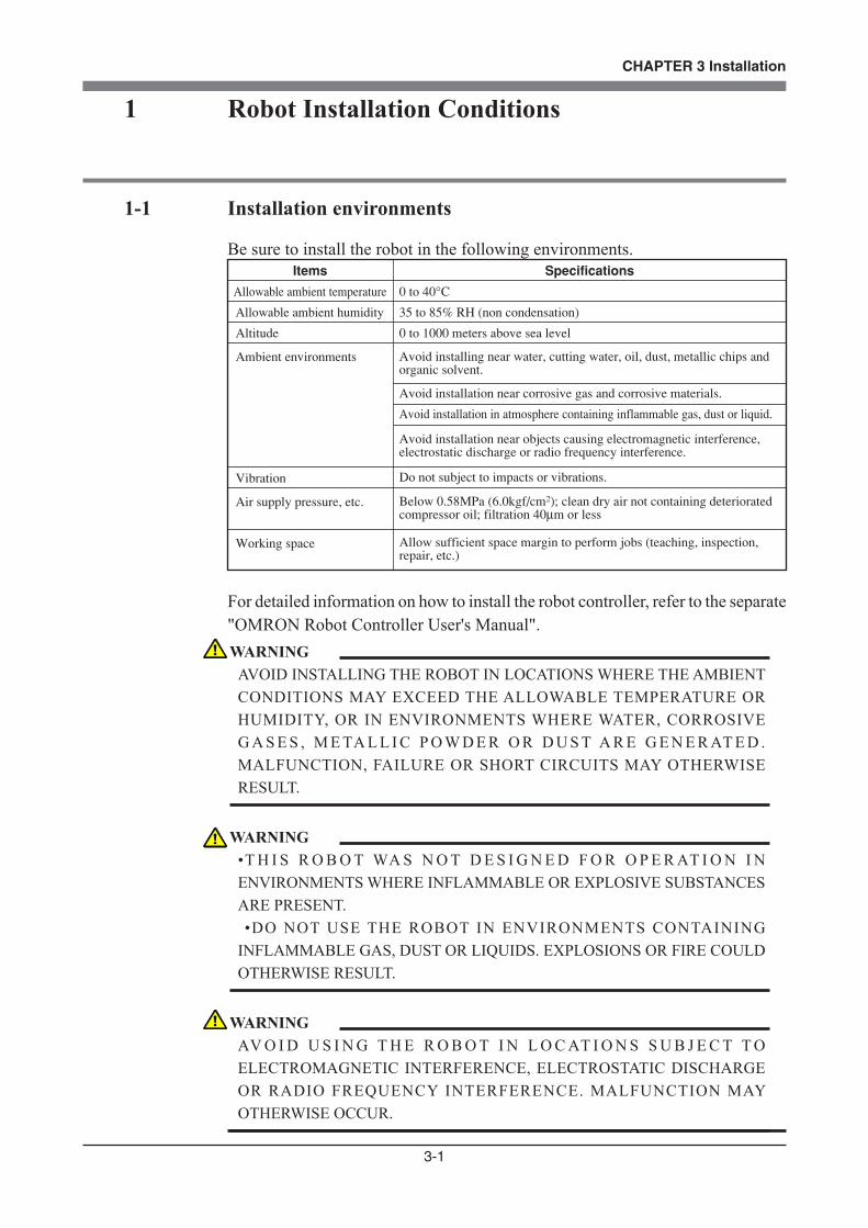
Be sure to install the robot in the following environments.Items
Allowable ambient temperature
Allowable ambient humidity
Altitude
Ambient environments
Vibration
Air supply pressure, etc.
Working space
Specifications
0 to 40°C
35 to 85% RH (non condensation)
0 to 1000 meters above sea level
Avoid installing near water, cutting water, oil, dust, metallic chips and organic solvent.
Avoid installation near corrosive gas and corrosive materials.
Avoid installation in atmosphere containing inflammable gas, dust or liquid.
Avoid installation near objects causing electromagnetic interference, electrostatic discharge or radio frequency interference.
Do not subject to impacts or vibrations.
Below 0.58MPa (6.0kgf/cm2); clean dry air not containing deteriorated compressor oil; filtration 40µm or less
Allow sufficient space margin to perform jobs (teaching, inspection, repair, etc.)
For detailed information on how to install the robot controller, refer to the separate "OMRON Robot Controller User's Manual".
WARNINGAVOID INSTALLING THE ROBOT IN LOCATIONS WHERE THE AMBIENT CONDITIONS MAY EXCEED THE ALLOWABLE TEMPERATURE OR HUMIDITY, OR IN ENVIRONMENTS WHERE WATER, CORROSIVE G A S E S , M E TA L L I C P O W D E R O R D U S T A R E G E N E R AT E D . MALFUNCTION, FAILURE OR SHORT CIRCUITS MAY OTHERWISE RESULT.
WARNING• T H I S R O B O T WA S N O T D E S I G N E D F O R O P E R AT I O N I N ENVIRONMENTS WHERE INFLAMMABLE OR EXPLOSIVE SUBSTANCES ARE PRESENT. •DO NOT USE THE ROBOT IN ENVIRONMENTS CONTAINING INFLAMMABLE GAS, DUST OR LIQUIDS. EXPLOSIONS OR FIRE COULD OTHERWISE RESULT.
WARNINGAV O I D U S I N G T H E R O B O T I N L O C AT I O N S S U B J E C T T O ELECTROMAGNETIC INTERFERENCE, ELECTROSTATIC DISCHARGE OR RADIO FREQUENCY INTERFERENCE. MALFUNCTION MAY OTHERWISE OCCUR.
3-2
CHAPTER 3 Installation
WARNINGDO NOT USE THE ROBOT IN LOCATIONS SUBJECT TO EXCESSIVE VIBRATION. ROBOT INSTALLATION BOLTS MAY OTHERWISE BECOME LOOSE CAUSING THE MANIPULATOR TO FALL OVER.
CAUTIONA POSITIONING ERROR MAY OCCUR IF THE MACHINE HARNESS, USER SIGNAL CABLES OR AIR TUBES HAVE DETERIORATED DUE TO IMPROPER INSTALLATION ENVIRONMENT.
3-3
CHAPTER 3 Installation
1-2 Installation base
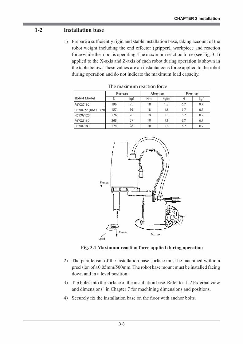
1) Prepare a sufficiently rigid and stable installation base, taking account of the robot weight including the end effector (gripper), workpiece and reaction force while the robot is operating. The maximum reaction force (see Fig. 3-1) applied to the X-axis and Z-axis of each robot during operation is shown in the table below. These values are an instantaneous force applied to the robot during operation and do not indicate the maximum load capacity.
Robot Model
R6YXC180
R6YXG220,R6YXC220
FXmax MXmax FZmax
The maximum reaction force
N kgf Nm kgfm N kgf
196 20 18 1.8 6.7 0.7
157 16 18 1.8 6.7 0.7
R6YXG120 276 28 18 1.8 6.7 0.7
R6YXG150 265 27 18 1.8 6.7 0.7
R6YXG180 274 28 18 1.8 6.7 0.7
Fxmax
FzmaxMxmax
Load
Fig. 3.1 Maximum reaction force applied during operation
2) The parallelism of the installation base surface must be machined within a precision of ±0.05mm/500mm. The robot base mount must be installed facing down and in a level position.
3) Tap holes into the surface of the installation base. Refer to "1-2 External view and dimensions" in Chapter 7 for machining dimensions and positions.
4) Securely fix the installation base on the floor with anchor bolts.
3-4
CHAPTER 3 Installation
WARNINGDO NOT PLACE THE ROBOT ON A MOVING INSTALLATION BASE. EXCESSIVE LOADS WILL BE APPLIED TO THE ROBOT ARM BY MOVEMENT OF THE INSTALLATION BASE, RESULTING IN DAMAGE TO THE ROBOT.
CAUTIONTHE MANIPULATOR POSITIONING MIGHT DECREASE IF THE INSTALLATION SURFACE PRECISION IS INSUFFICIENT.
CAUTIONIF THE INSTALLATION BASE IS NOT SUFFICIENTLY RIGID AND STABLE OR A THIN METALLIC PLATE IS ATTACHED TO THE INSTALLATION BASE, VIBRATION (RESONANCE) MAY OCCUR DURING O P E R AT I O N , C A U S I N G D E T R I M E N TA L E F F E C T S O N T H E MANIPULATOR WORK.

3-5
CHAPTER 3 Installation
2 Installation
2-1 Unpacking
The package comes with a robot manipulator, a robot controller and accessories, according to the order specifications. Transport the package by dolly to near the installation base before unpacking. Take sufficient care not to apply shocks to the equipment when unpacking it.
Robot controller andaccessories
Robot manipulator
Case
Fig. 3-2 Packed state
WARNINGTHE ROBOT AND CONTROLLER ARE HEAVY. TAKE SUFFICIENT CARE NOT TO DROP THEM DURING MOVING OR UNPACKING AS THIS MAY DAMAGE THE EQUIPMENT OR CAUSE BODILY INJURY.
CAUTIONWHEN MOVING THE ROBOT OR CONTROLLER BY EQUIPMENT SUCH AS A FOLKLIFT THAT REQUIRE A LICENSE, ONLY PROPERLY QUALIFIED PERSONNEL MAY OPERATE IT. THE EQUIPMENT AND TOOLS USED FOR MOVING THE ROBOT SHOULD BE SERVICED DAILY.
3-6
CHAPTER 3 Installation
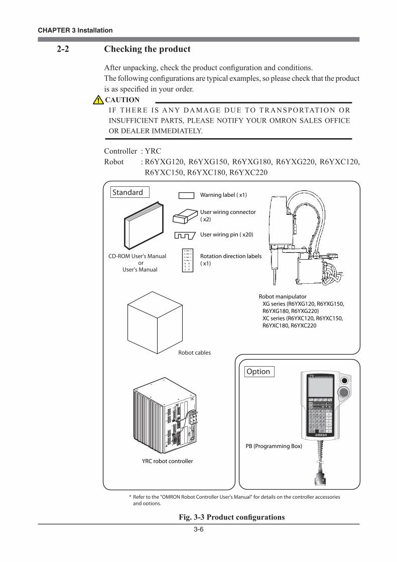
2-2 Checking the product
After unpacking, check the product configuration and conditions.The following configurations are typical examples, so please check that the product is as specified in your order.
Controller : YRCRobot : R6YXG120, R6YXG150, R6YXG180, R6YXG220, R6YXC120, R6YXC150, R6YXC180, R6YXC220
A BX YZ R
PBMO TOR
XM
YM
ZM
RM
PWR
S R V
SAFE T Y
COM
STD.DIO
ROBI/O
ZR
OP.1OP.3
OP.2OP.4
ACINN
P
N1
L1
L
N
SE L
B AT T
ZR
XYB AT T
ROB
XY
I/O
13 14EX T.E-S TOP
ERR
YRC
OMRON
Robot cables
Robot manipulator XG series (R6YXG120, R6YXG150, R6YXG180, R6YXG220) XC series (R6YXC120, R6YXC150, R6YXC180, R6YXC220
CD-ROM User's Manual or
User's Manual
YRC robot controller
Warning label ( x1)
User wiring connector ( x2)
User wiring pin ( x20)
Rotation direction labels ( x1)
Standard
PB (Programming Box)
Option
* Refer to the "OMRON Robot Controller User's Manual" for details on the controller accessories and options.
OMRON
Fig. 3-3 Product configurations
CAUTIONI F T H E R E I S A N Y D A M A G E D U E TO T R A N S P O RTAT I O N O R INSUFFICIENT PARTS, PLEASE NOTIFY YOUR OMRON SALES OFFICE OR DEALER IMMEDIATELY.
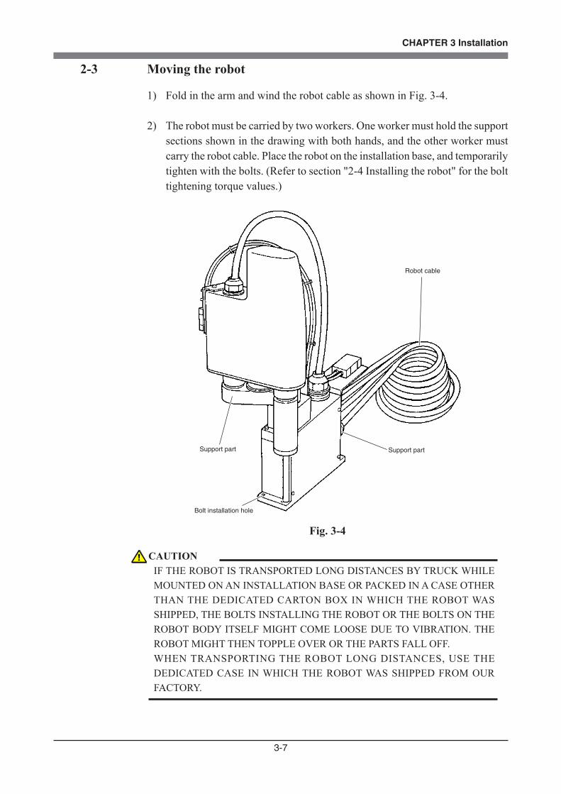
3-7
CHAPTER 3 Installation
2-3 Moving the robot
1) Fold in the arm and wind the robot cable as shown in Fig. 3-4.
2) The robot must be carried by two workers. One worker must hold the support sections shown in the drawing with both hands, and the other worker must carry the robot cable. Place the robot on the installation base, and temporarily tighten with the bolts. (Refer to section "2-4 Installing the robot" for the bolt tightening torque values.)
Support part
Robot cable
Bolt installation hole
Support part
Fig. 3-4
CAUTIONIF THE ROBOT IS TRANSPORTED LONG DISTANCES BY TRUCK WHILE MOUNTED ON AN INSTALLATION BASE OR PACKED IN A CASE OTHER THAN THE DEDICATED CARTON BOX IN WHICH THE ROBOT WAS SHIPPED, THE BOLTS INSTALLING THE ROBOT OR THE BOLTS ON THE ROBOT BODY ITSELF MIGHT COME LOOSE DUE TO VIBRATION. THE ROBOT MIGHT THEN TOPPLE OVER OR THE PARTS FALL OFF. WHEN TRANSPORTING THE ROBOT LONG DISTANCES, USE THE DEDICATED CASE IN WHICH THE ROBOT WAS SHIPPED FROM OUR FACTORY.
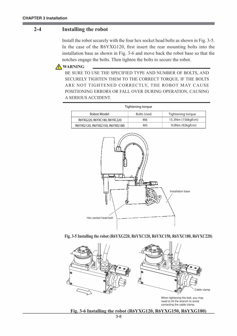
3-8
CHAPTER 3 Installation
2-4 Installing the robot
Install the robot securely with the four hex socket head bolts as shown in Fig. 3-5.In the case of the R6YXG120, first insert the rear mounting bolts into the installation base as shown in Fig. 3-6 and move back the robot base so that the notches engage the bolts. Then tighten the bolts to secure the robot.
M6 15.3Nm (156kgfcm)
Bolts UsedRobot Model
R6YXG220, R6YXC180, R6YXC220
Tightening torque
Tightening torque
M5 9.0Nm (92kgfcm)R6YXG120, R6YXG150, R6YXG180
Installation base
Hex socket head bolt
Fig. 3-5 Installing the robot (R6YXG220, R6YXC120, R6YXC150, R6YXC180, R6YXC220)
Cable clamp
When tightening the bolt, you may need to tilt the wrench to avoid contacting the cable clamp.
Fig. 3-6 Installing the robot (R6YXG120, R6YXG150, R6YXG180)
WARNINGBE SURE TO USE THE SPECIFIED TYPE AND NUMBER OF BOLTS, AND SECURELY TIGHTEN THEM TO THE CORRECT TORQUE. IF THE BOLTS ARE NOT TIGHTENED CORRECTLY, THE ROBOT MAY CAUSE POSITIONING ERRORS OR FALL OVER DURING OPERATION, CAUSING A SERIOUS ACCIDENT.
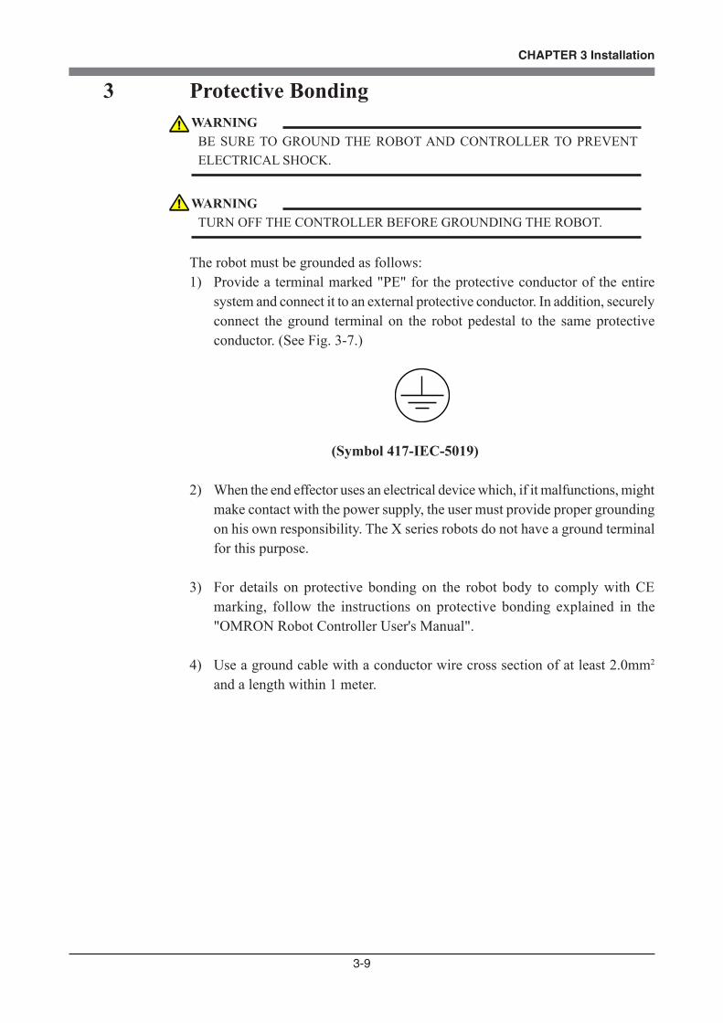
3-9
CHAPTER 3 Installation
3 Protective Bonding
The robot must be grounded as follows:1) Provide a terminal marked "PE" for the protective conductor of the entire
system and connect it to an external protective conductor. In addition, securely connect the ground terminal on the robot pedestal to the same protective conductor. (See Fig. 3-7.)
(Symbol 417-IEC-5019)
2) When the end effector uses an electrical device which, if it malfunctions, might make contact with the power supply, the user must provide proper grounding on his own responsibility. The X series robots do not have a ground terminal for this purpose.
3) For details on protective bonding on the robot body to comply with CE marking, follow the instructions on protective bonding explained in the "OMRON Robot Controller User's Manual".
4) Use a ground cable with a conductor wire cross section of at least 2.0mm2 and a length within 1 meter.
WARNINGBE SURE TO GROUND THE ROBOT AND CONTROLLER TO PREVENT ELECTRICAL SHOCK.
WARNINGTURN OFF THE CONTROLLER BEFORE GROUNDING THE ROBOT.
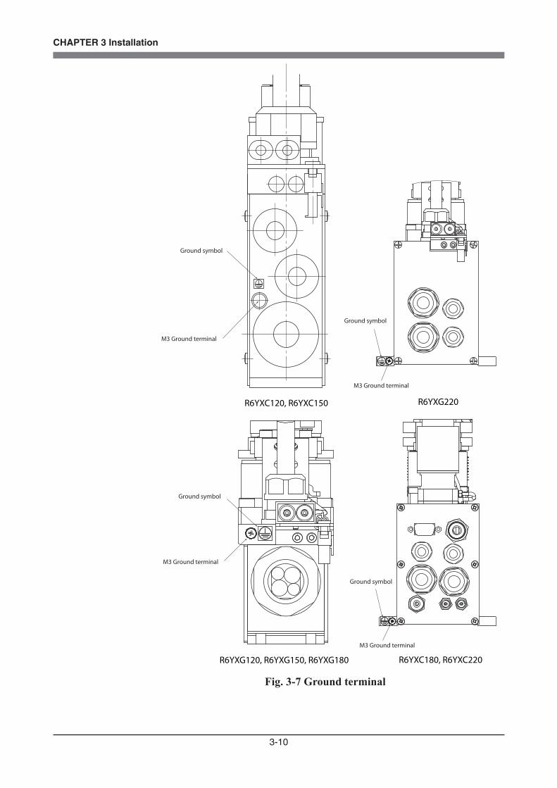
3-10
CHAPTER 3 Installation
R6YXC120, R6YXC150
R6YXG120, R6YXG150, R6YXG180
R6YXG220
R6YXC180, R6YXC220
M3 Ground terminal
Ground symbol
M3 Ground terminal
Ground symbol
M3 Ground terminal
Ground symbol
Ground symbol
M3 Ground terminal
Fig. 3-7 Ground terminal
3-11
CHAPTER 3 Installation
4 Robot Cable ConnectionThe robot cable is pre-connected to each robot. Correctly install the other end of the robot cable to the robot controller. After making connections, check the operation while referring to "6 Trial operation" in Chapter 1.
WARNING• BEFORE CONNECTING THE CABLES, CHECK THAT THERE ARE NO BENDS OR BREAKS IN THE CONNECTOR PINS OF THE ROBOT CABLE AND THAT THE CABLES ARE NOT DAMAGED. BENT OR BROKEN PINS OR CABLE DAMAGE MAY CAUSE MALFUNCTION OF THE ROBOT. • ENSURE THAT THE CONTROLLER IS OFF BEFORE CONNECTING THE ROBOT CABLE TO THE CONTROLLER.
WARNINGIN THE YRC CONTROLLER, THE MOTOR CONNECTORS XM AND ZM, AND YM AND RM EACH HAVE IDENTICAL SHAPES. IN ADDITION, THE PI CONNECTORS XY AND ZR HAVE IDENTICAL SHAPES. DO NOT CONFUSE THESE CONNECTORS WHEN MAKING CONNECTIONS. WRONG CONNECTIONS MAY RESULT IN MALFUNCTION AND HAZARDOUS SITUATIONS.
WARNING• IF THE CONNECTOR INSTALLATION IS INADEQUATE OR IF THERE A R E C O N TA C T FA I L U R E S I N T H E P I N S , T H E R O B O T M AY MALFUNCTION CAUSING A HAZARDOUS SITUATION. RECONFIRM THAT EACH CONNECTOR IS SECURELY INSTALLED BEFORE TURNING ON THE CONTROLLER. • TO ATTACH THE PI CONNECTOR SECURELY, TIGHTEN THE SCREWS SUPPLIED WITH THE ROBOT. • TAKE CAUTION NOT TO APPLY AN EXCESSIVE LOAD TO THE CONNECTORS DUE TO STRESS OR TENSION ON THE CABLES.
WARNINGLAY OUT THE CABLES SO THAT THEY DO NOT OBSTRUCT THE MOVEMENT OF THE MANIPULATOR. DETERMINE THE ROBOT WORK AREA IN WHICH THE ROBOT CABLES WILL NOT INTERFERE WITH THE LOAD OR WORKPIECE PICKED UP BY THE MANIPULATOR. IF THE ROBOT CABLES INTERFERE WITH THE MOVABLE PARTS OF THE ROBOT, THE CABLES MAY BE DAMAGED CAUSING MALFUNCTION AND HAZARDOUS SITUATIONS. FOR THE EXTERNAL VIEW AND DIMENSIONS OF EACH ROBOT, REFER TO THE DIMENSIONAL OUTLINES LISTED IN OUR ROBOT CATALOG.
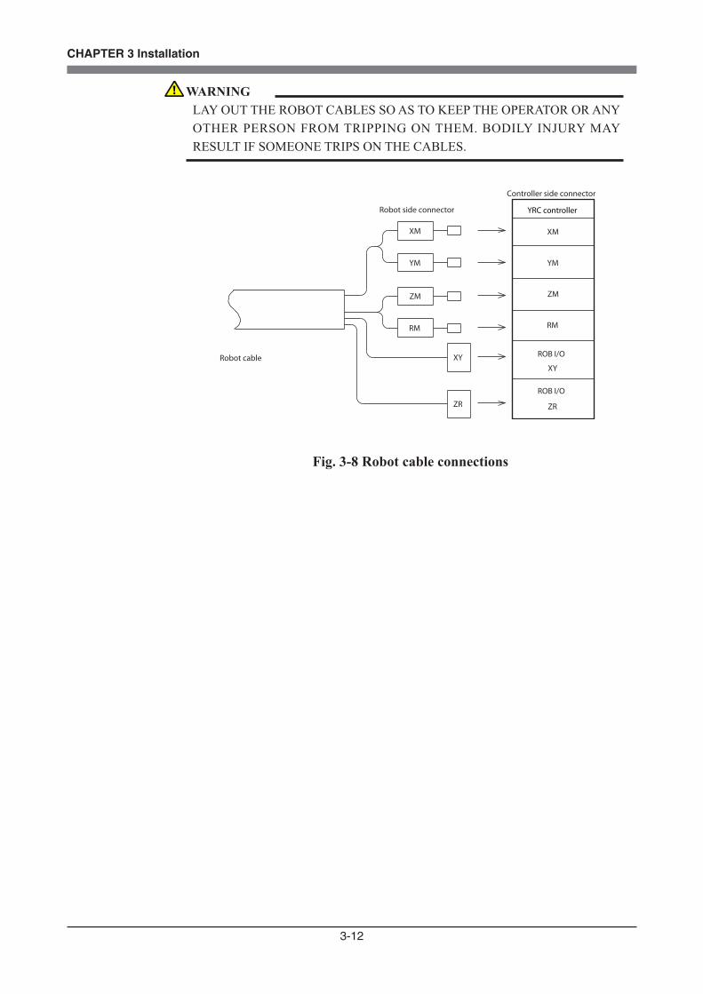
3-12
CHAPTER 3 Installation
Robot cable
Controller side connector
Robot side connector YRC controller
XM
YM
ZM
RM
ROB I/O
XY
ROB I/O
ZR
XM
YM
ZM
RM
XY
ZR
Fig. 3-8 Robot cable connections
WARNINGLAY OUT THE ROBOT CABLES SO AS TO KEEP THE OPERATOR OR ANY OTHER PERSON FROM TRIPPING ON THEM. BODILY INJURY MAY RESULT IF SOMEONE TRIPS ON THE CABLES.
3-13
CHAPTER 3 Installation
5 User Wiring and User Tubing
1) The robot has a user signal wire and air tube laid in parallel with the robot body's machine harness. The signal wires and air tubes that can be used are shown below.
User wiring6 wires
User tubingø3, 2 tubes
User wiring8 wires
User tubingø4, 2 tubes
R6YXC120, R6YXC150, R6YXG220 robots
R6YXG120, R6YXG150, R6YXG180,R6YXC180, R6YXC220 robots
(Robot models for custom specifications may have different wiring or tubing.)The specifications of the user wires and air tubes are shown below. Always observe the specifications.
30V
1.3A (R6YXC120, R6YXC150, R6YXC180, R6YXC220, R6YXG220)1.5A (R6YXG120, R6YXG150, R6YXG180)
0.1mm2
No
User signal cable
Rated voltage
Allowable current
Nominal cross-section area of conductor
Shield
User Tubing
Maximum pressure
Outer diameter x inner diameter
Fluid
0.58MPa (6Kgf/cm2)
Dry clean air not containing deteriorated compressor oil; �ltration 40um or less
ø3xø1.5 (R6YXC120, R6YXC150, R6YXC180, R6YXC220, R6YXG220)
ø4xø2.5 (R6YXG120, R6YXG150, R6YXG180)
2) User wiring connectors and user piping joints are provided on the arm side and base side. Refer to "Chapter 7, 1-2. External view and dimensions" for the positions.
WARNINGALWAYS TURN OFF THE CONTROLLER AND SHUT OFF AIR SUPPLY BEFORE ATTEMPTING WIRING AND PIPING WORK. IF AIR OR POWER IS SUPPLIED DURING THIS WORK, THE MANIPULATOR MAY MOVE ERRONEOUSLY CAUSING A HAZARDOUS SITUATION.
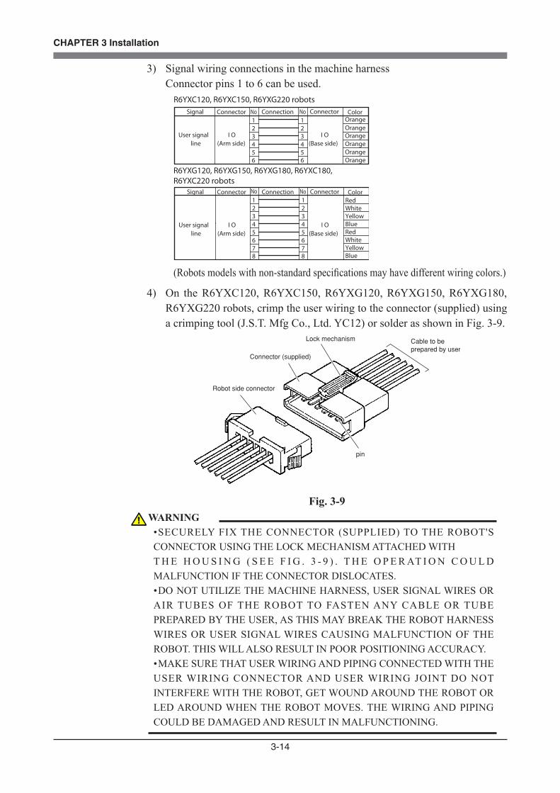
3-14
CHAPTER 3 Installation
3) Signal wiring connections in the machine harnessConnector pins 1 to 6 can be used.
I O(Base side)4
321
4321
665 5
User signal line
I O(Arm side)
Signal ConnectionConnector No ColorConnector
I O(Base side)
User signal line
I O(Arm side)
Signal ConnectionConnector ColorConnector
NoOrangeOrangeOrangeOrangeOrangeOrange
R6YXC120, R6YXC150, R6YXG220 robots
4321
4321
665 5
7 78 8
No NoRedWhiteYellowBlueRedWhiteYellowBlue
R6YXG120, R6YXG150, R6YXG180, R6YXC180, R6YXC220 robots
(Robots models with non-standard specifications may have different wiring colors.)
4) On the R6YXC120, R6YXC150, R6YXG120, R6YXG150, R6YXG180, R6YXG220 robots, crimp the user wiring to the connector (supplied) using a crimping tool (J.S.T. Mfg Co., Ltd. YC12) or solder as shown in Fig. 3-9.
Robot side connector
Connector (supplied)
Lock mechanism
pin
Cable to be prepared by user
Fig. 3-9 WARNING
• SECURELY FIX THE CONNECTOR (SUPPLIED) TO THE ROBOT'S CONNECTOR USING THE LOCK MECHANISM ATTACHED WITH T H E H O U S I N G ( S E E F I G . 3 - 9 ) . T H E O P E R AT I O N C O U L D MALFUNCTION IF THE CONNECTOR DISLOCATES. • DO NOT UTILIZE THE MACHINE HARNESS, USER SIGNAL WIRES OR AIR TUBES OF THE ROBOT TO FASTEN ANY CABLE OR TUBE PREPARED BY THE USER, AS THIS MAY BREAK THE ROBOT HARNESS WIRES OR USER SIGNAL WIRES CAUSING MALFUNCTION OF THE ROBOT. THIS WILL ALSO RESULT IN POOR POSITIONING ACCURACY. • MAKE SURE THAT USER WIRING AND PIPING CONNECTED WITH THE USER WIRING CONNECTOR AND USER WIRING JOINT DO NOT INTERFERE WITH THE ROBOT, GET WOUND AROUND THE ROBOT OR LED AROUND WHEN THE ROBOT MOVES. THE WIRING AND PIPING COULD BE DAMAGED AND RESULT IN MALFUNCTIONING.
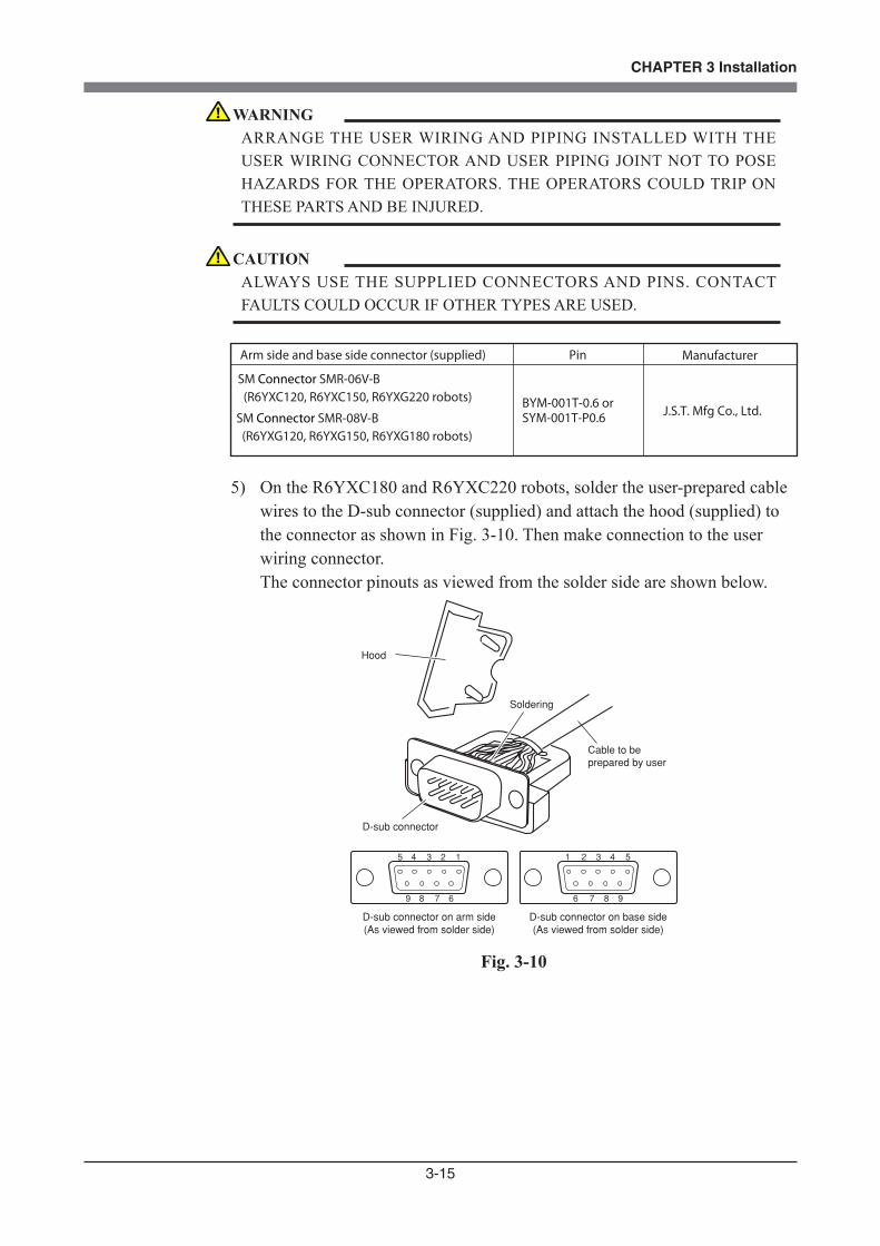
3-15
CHAPTER 3 Installation
Arm side and base side connector (supplied) Pin Manufacturer
SM Connector SMR-06V-B (R6YXC120, R6YXC150, R6YXG220 robots)
SM Connector SMR-08V-B (R6YXG120, R6YXG150, R6YXG180 robots)
BYM-001T-0.6 or SYM-001T-P0.6
J.S.T. Mfg Co., Ltd.
5) On the R6YXC180 and R6YXC220 robots, solder the user-prepared cable wires to the D-sub connector (supplied) and attach the hood (supplied) to the connector as shown in Fig. 3-10. Then make connection to the user wiring connector. The connector pinouts as viewed from the solder side are shown below.
Hood
D-sub connector
Cable to beprepared by user
Soldering
D-sub connector on arm side(As viewed from solder side)
D-sub connector on base side(As viewed from solder side)
5 4 3 2 1
9 8 7 6
1 2 3 4 5
6 7 8 9
Fig. 3-10
WARNINGARRANGE THE USER WIRING AND PIPING INSTALLED WITH THE USER WIRING CONNECTOR AND USER PIPING JOINT NOT TO POSE HAZARDS FOR THE OPERATORS. THE OPERATORS COULD TRIP ON THESE PARTS AND BE INJURED.
CAUTIONALWAYS USE THE SUPPLIED CONNECTORS AND PINS. CONTACT FAULTS COULD OCCUR IF OTHER TYPES ARE USED.
3-16
CHAPTER 3 Installation
DE-C1-J6RDE-9S-NRDE-9P-NR
D-sub connector on arm side D-sub connector on base side Hood
Manufacturer : Japan Aviation Electronics Industry, Limited.
D-sub connectors (supplied with robot)
6) To check the operation and signal transmission between the end effector and the controller or peripheral equipment after making connections, refer to "6. Trial operation" in Chapter 1.
WARNING• SECURELY ATTACH THE D-SUB CONNECTOR (SUPPLIED WITH THE ROBOT) INTO THE D-SUBCONNECTOR ON THE ROBOT SIDE, BY TIGHTENING THE SCREWS ON THE CONNECTOR HOOD. IF THIS CONNECTOR COMES LOOSE OR COMES OFF, MALFUNCTION MAY RESULT. •AVOID FASTENING THE USER CABLE OR TUBE WITH THE MACHINE HARNESS, AS THIS MAY LEAD TO HARNESS BREAKAGE AND MALFUNCTION. •MAKE SURE THAT THE USER CABLE ATTACHED TO THE D-SUB CONNECTOR FOR USER WIRING AND THE TUBE ATTACHED TO THE BULKHEAD UNION FOR USER TUBING WILL NOT INTERFERE WITH THE ROBOT MOVEMENT, ENTANGLE AROUND THE ROBOT OR FLAP AROUND DURING OPERATION. WIRING AND TUBING MIGHT THEN BE DAMAGED CAUSING MALFUNCTION OF THE ROBOT. • LAY OUT THE USER CABLE ATTACHED TO THE D-SUB CONNECTOR FOR USER WIRING AND THE TUBE ATTACHED TO THE BULKHEAD UNION FOR USER TUBING SO THAT THEY DO NOT OBSTRUCT THE MOVEMENT OF THE OPERATOR OR ANY OTHER PERSONS. BODILY INJURY MAY RESULT IF ANYONE TRIPS ON THE CABLE OR AIR TUBE.
CAUTION• THE D-SUB CONNECTOR SUPPLIED WITH THE ROBOT SHOULD BE CONNECTED TO THE ARM SIDE BY PIN CONTACT, AND TO THE PEDESTAL SIDE BY SOCKET CONTACT. USE CAUTION AT THESE POINTS WHEN SOLDERING. • BE SURE TO USE THE D-SUB CONNECTOR AND HOOD WHICH ARE SUPPLIED WITH THE ROBOT. USING OTHER TYPES MAY RESULT IN CONTACT FAILURE.

3-17
CHAPTER 3 Installation
6 Connecting a Suction Hose (R6YXC120, R6YXC150, R6YXC180, R6YXC220)
The R6YXC120 and R6YXC150 have three suction tubings on the rear of the manipulator base: one (ø 6) for the base interior, one (ø 6) for the X, Y and R axis joints, and one (ø 3) for the R-axis bellows.The R6YXC180 and R6YXC220 have two suction tubings on the rear of the manipulator base: one (ø 8) for the base interior and the other (ø 6) for the X, Y and R axis joints.The required degree of cleanliness can be maintained by sucking air through these tubings.For the suction amount versus degree of cleanliness, see "1-1 Basic specifications" in chapter 7. For the locations of the suction tubings, see "1-2 External view and dimensions" in chapter 7.
WARNINGALWAYS TURN OFF THE ROBOT CONTROLLER AND SHUT OFF AIR SUPPLY BEFORE CONNECTING A SUCTION HOSE.
WARNINGLAY OUT THE SUCTION HOSES SO AS TO KEEP THE OPERATOR OR ANY OTHER PERSON FROM TRIPPING ON THEM. BODILY INJURY MAY RESULT IF SOMEONE TRIPS ON THE HOSES.
CAUTIONCAREFULLY CONNECT THE SUCTION HOSES TO THE SUCTION COUPLERS SO THAT THEY DO NOT OBSTRUCT THE MOVEMENT OF THE ROBOT MANIPULATOR.
3-18
CHAPTER 3 Installation
7 Attaching the End Effector
7-1 R-axis tolerable moment of inertia and acceleration coefficient
1) The moment of inertia of a load (end effector and workpiece) that can be attached to the R-axis is limited by the strength of the robot drive unit and residual vibration during positioning. It is therefore necessary to reduce the acceleration coefficient in accordance with the moment of inertia.
2) The R-axis tolerable moment of inertia and the acceleration coefficient versus R-axis moment of inertia for each robot model are shown in Fig. 3-11 to Fig. 3-16 on the subsequent pages. The symbols AX, AY, and AR in each figure respectively indicate the acceleration coefficients of the X-axis, Y-axis and R-axis. The symbol IR (JR) is the moment of inertia of the load around the R-axis and m is the tip mass.
Example: R6YXC120 Assume that the mass of the load installed to the R-axis is 0.15kg and the
moment of inertia around the R-axis is 0.0005kgm2 (0.005kgfcmsec2). When the tip mass parameter is set to 0.2kg, the robot can be operated by reducing the X, Y and R-axis acceleration coefficients to 50%, as can be seen from Fig. 3-11.
Be sure to select an optimum tip mass and acceleration coefficient parameters that meet the mass of the load and moment of inertia before using the robot.
To make settings for the tip mass and acceleration coefficient, refer to the separate "OMRON Robot Controller User's Manual".
3) Methods for calculating the moment of inertia of the load are shown in Section "7-2 Equation for moment of inertia calculation", however, it is not easy to precisely figure out these values.
If a calculated value smaller than the actual moment of inertia is set, residual vibrations may occur. If this happens, reduce the acceleration coefficient parameter even further.
CAUTIONTHE ROBOT MUST BE OPERATED WITH CORRECT TOLERABLE MOMENT OF INERTIA AND ACCELERATION COEFFICIENTS ACCORDING TO THE MANIPULATOR TIP MASS AND MOMENT OF INERTIA. IF THIS IS NOT OBSERVED, PREMATURE END TO THE LIFE OF THE DRIVE UNITS, DAMAGE TO THE ROBOT PARTS OR RESIDUAL VIBRATION DURING POSITIONING MAY RESULT.
3-19
CHAPTER 3 Installation
CAUTIONDEPENDING ON THE Z-AXIS POSITION, VIBRATION MAY OCCUR WHEN THE X, Y OR R-AXIS MOVES. IF THIS HAPPENS, REDUCE THE X, Y OR R-AXIS ACCELERATION TO AN APPROPRIATE LEVEL.
CAUTIONIF THE MOMENT OF INERTIA IS TOO LARGE, VIBRATION MAY OCCUR ON THE Z-AXIS DEPENDING ON ITS OPERATION POSITION. IF THIS HAPPENS, REDUCE THE Z-AXIS ACCELERATION TO AN APPRORIATE LEVEL.

3-20
CHAPTER 3 Installation
7-1-1 Acceleration coefficient vs. moment of inertia (R6YXC120)
0
00.00050.005
0.00100.010
W=0.1kg
W=0.2kg
W=0.3kg
0.00150.015
0.00200.020
Ir (kgm2)Jr (kgfcmsec2)
100
80
60
40
20
AX, AY, AR (%)0.00025 (0.0025)
0
00.00050.005
0.00100.010
0.00150.015
0.00200.020
Ir (kgm2)Jr (kgfcmsec2)
100
80
60
40
20
AX, AY, AR (%)0.0008 (0.00008)
0.0005 (0.00005)
0
00.00050.005
0.00100.010
0.00150.015
0.00200.020
Ir (kgm2)Jr (kgfcmsec2)
100
80
60
40
20
AX, AY, AR (%)
0.0011 (0.011)
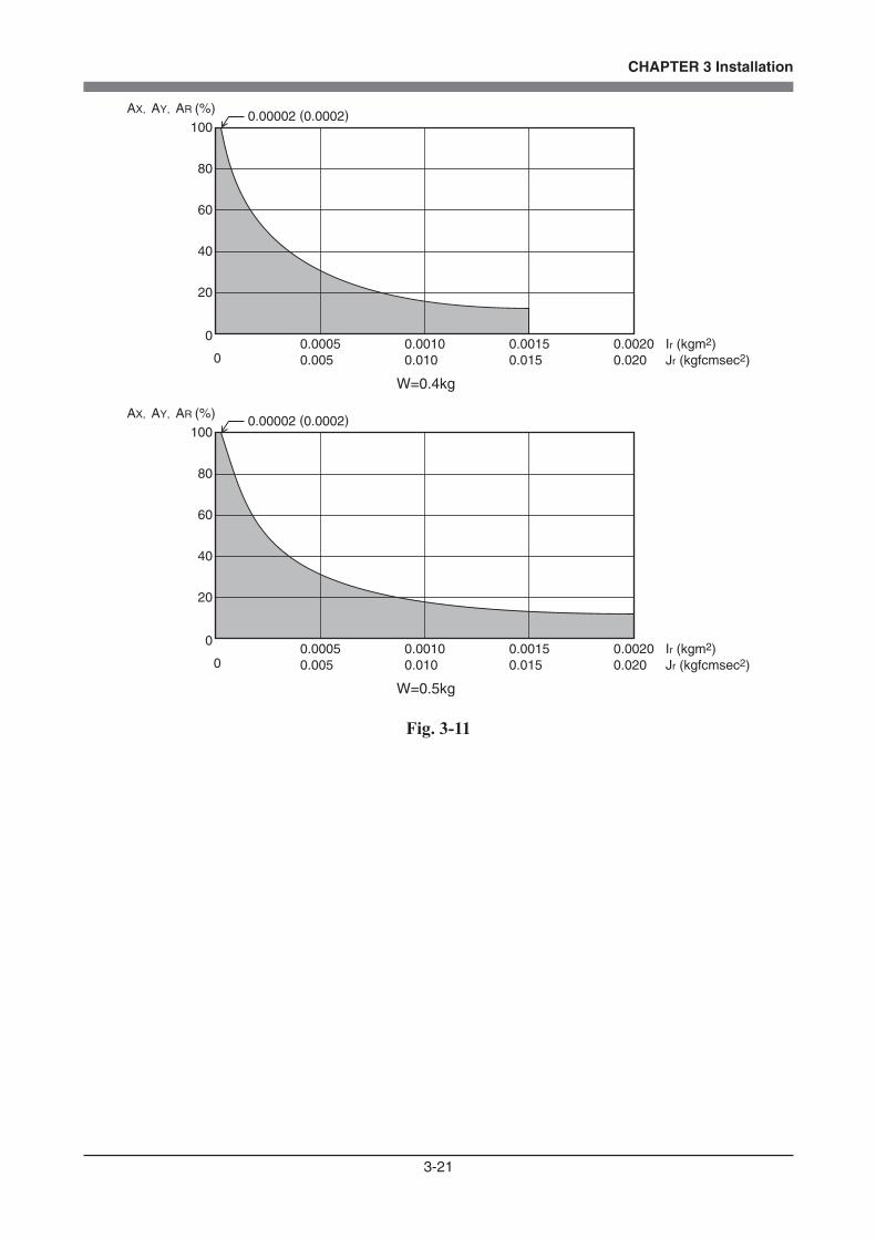
3-21
CHAPTER 3 Installation
W=0.4kg
0
00.00050.005
0.00100.010
0.00150.015
0.00200.020
Ir (kgm2)Jr (kgfcmsec2)
100
80
60
40
20
AX, AY, AR (%)0.00002 (0.0002)
W=0.5kg
0
00.00050.005
0.00100.010
0.00150.015
0.00200.020
Ir (kgm2)Jr (kgfcmsec2)
100
80
60
40
20
AX, AY, AR (%)0.00002 (0.0002)
Fig. 3-11

3-22
CHAPTER 3 Installation
7-1-2 Acceleration coefficient vs. moment of inertia (R6YXC150)
0
00.00050.005
0.00100.010
W=0.1kg
W=0.2kg
W=0.3kg
0.00150.015
0.00200.020
Ir (kgm2)Jr (kgfcmsec2)
100
80
60
40
20
AX, AY, AR (%)0.00004 (0.0004)
0.00025(0.0025)
0
00.00050.005
0.00100.010
0.00150.015
0.00200.020
Ir (kgm2)Jr (kgfcmsec2)
100
80
60
40
20
AX, AY, AR (%)0.00018 (0.0018)
0
00.00050.005
0.00100.010
0.00150.015
0.00200.020
Ir (kgm2)Jr (kgfcmsec2)
100
80
60
40
20
AX, AY, AR (%)
0.0011 (0.011)
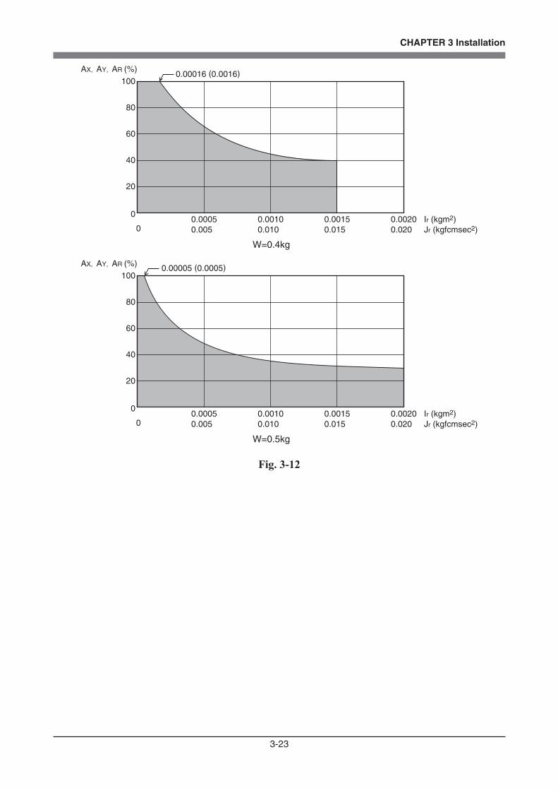
3-23
CHAPTER 3 Installation
W=0.4kg
W=0.5kg
0
00.00050.005
0.00100.010
0.00150.015
0.00200.020
Ir (kgm2)Jr (kgfcmsec2)
100
80
60
40
20
AX, AY, AR (%)0.00016 (0.0016)
0
00.00050.005
0.00100.010
0.00150.015
0.00200.020
Ir (kgm2)Jr (kgfcmsec2)
100
80
60
40
20
AX, AY, AR (%) 0.00005 (0.0005)
Fig. 3-12

3-24
CHAPTER 3 Installation
7-1-3 Acceleration coefficient vs. moment of inertia (R6YXC180, R6YXC220, R6YXG220)
W=0.9, 1.0kg
0.0005 (0.005)
0.0005 (0.005)
0.0005 (0.005)
0
00.0050.05
0.010.1
Ir (kgm2)Jr (kgfcmsec2)
100
80
60
40
20
AX, AY, AR (%)
W=0.5 to 0.8kg
0
00.0050.05
0.010.1
Ir (kgm2)Jr (kgfcmsec2)
100
80
60
40
20
AX, AY, AR (%)
W=0.1 to 0.4kg
0
00.0050.05
0.010.1
Ir (kgm2)Jr (kgfcmsec2)
100
80
60
40
20
AX, AY, AR (%)
Fig. 3-13
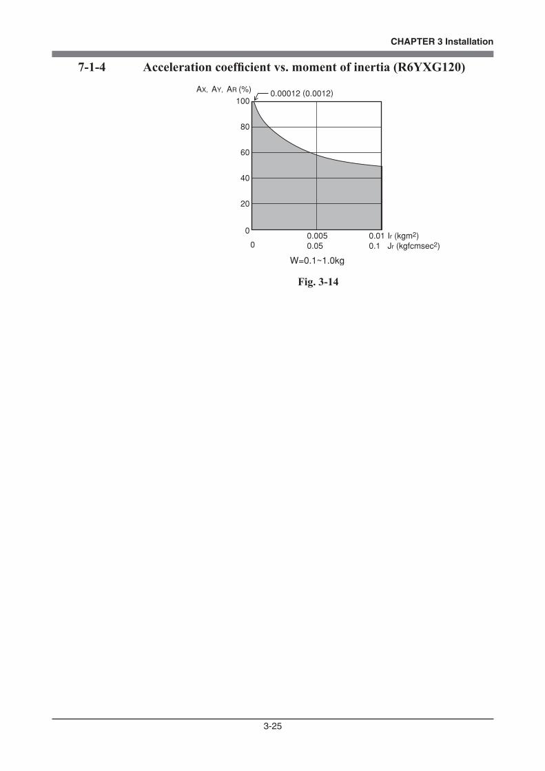
3-25
CHAPTER 3 Installation
7-1-4 Acceleration coefficient vs. moment of inertia (R6YXG120)
0.00012 (0.0012)
W=0.1~1.0kg
0
00.0050.05
0.010.1
Ir (kgm2)Jr (kgfcmsec2)
100
80
60
40
20
AX, AY, AR (%)
Fig. 3-14

3-26
CHAPTER 3 Installation
7-1-5 Acceleration coefficient vs. moment of inertia (R6YXG150)
0.00033 (0.0033)
0.00006 (0.0006)
W=0.4~1.0kg
0
00.0050.05
0.010.1
Ir (kgm2)Jr (kgfcmsec2)
100
80
60
40
20
AX, AY, AR (%)
W=0.1~0.3kg
0
00.0050.05
0.010.1
Ir (kgm2)Jr (kgfcmsec2)
100
80
60
40
20
AX, AY, AR (%)
Fig. 3-15
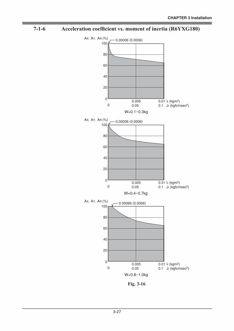
3-27
CHAPTER 3 Installation
7-1-6 Acceleration coefficient vs. moment of inertia (R6YXG180)
W=0.8~1.0kg
0.00066 (0.0066)
0.00006 (0.0006)
0.00006 (0.0006)
0
00.0050.05
0.010.1
Ir (kgm2)Jr (kgfcmsec2)
100
80
60
40
20
AX, AY, AR (%)
W=0.4~0.7kg
0
00.0050.05
0.010.1
Ir (kgm2)Jr (kgfcmsec2)
100
80
60
40
20
AX, AY, AR (%)
W=0.1~0.3kg
0
00.0050.05
0.010.1
Ir (kgm2)Jr (kgfcmsec2)
100
80
60
40
20
AX, AY, AR (%)
Fig. 3-16

3-28
CHAPTER 3 Installation
7-2 Equation for moment of inertia calculation
Usually the R axis load is not a simple form, and the calculation of the moment of inertia is not easy.As a method, the load is replaced with several factors that resemble a simple form for which the moment of inertia can be calculated. The total of the moment of inertia for these factors is then obtained.The objects and equations often used for the calculation of the moment of inertia are shown below. Incidentally, there is the following relation:
1) Moment of inertia for material particle The equation for the moment of inertia for a material particle that has a
rotation center such as shown in Fig. 3-17 is as follows: This is used as an approximate equation when x is larger than the object size.
x
J= Wx g
2
(kgfcmsec2)
g : Gravitational acceleration (cm/sec2)m : Mass of material particle (kg)
... (Eq. 3.1)
I= mx2 (kgm2)
W : Weight of material particle (kgf)
Fig. 3-17
2) Moment of inertia for cylinder (part 1) The equation for the moment of inertia for a cylinder that has a rotation center
such as shown in Fig. 3-18 is given below.
D
h
J=ρπ D h
32gWD8g
=4 2
(kgfcmsec2)
... (Eq. 3.2)
I=ρπ D h
32mD8
=4 2
(kgm2)
ρ : Density (kg/m3, kg/cm3)g : Gravitational acceleration (cm/sec2)
m : Mass of cylinder (kg)W : Weight of cylinder (kgf)
Fig. 3-18

3-29
CHAPTER 3 Installation
3) Moment of inertia for cylinder (part 2) The equation for the moment of inertia for a cylinder that has a rotation center
such as shown in Fig. 3-19 is given below.
h
D
2h
J=ρπ D h
16gW4g
=2
... (Eq. 3.3)
D4
h3
(2 2
+ )D4
h3
(2 2
+ )
I=ρπ D h
16m4
=2 D
4h3
(2 2
+ )D4
h3
(2 2
+ )
ρ : Density (kg/m3, kg/cm3)g : Gravitational acceleration (cm/sec2)
m : Mass of cylinder (kg)W : Weight of cylinder (kgf)
(kgfcmsec2)
(kgm2)
Fig. 3-194) Moment of inertia for prism The equation for the moment of inertia for a prism that has a rotation center
as shown in Fig. 3-20 is given as follows.
J=ρ abc(a +b )
12gW(a +b )
12g=
2 2
... (Eq. 3.4)
a
c
b
1/2a
2 2
I=ρ abc(a +b )
12m(a +b )
12=
2 22 2
(kgfcmsec2)
(kgm2)
ρ : Density (kg/m3, kg/cm3)g : Gravitational acceleration (cm/sec2)
m : Mass of prism (kg)W : Weight of prism (kgf)
Fig. 3-20
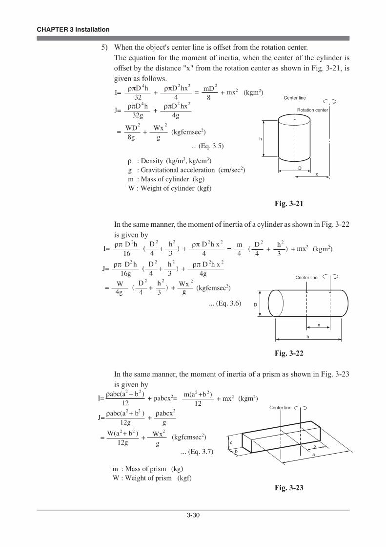
3-30
CHAPTER 3 Installation
5) When the object's center line is offset from the rotation center. The equation for the moment of inertia, when the center of the cylinder is
offset by the distance "x" from the rotation center as shown in Fig. 3-21, is given as follows.
D
h
J=ρπD h
32g
WD8g
=
4
2
... (Eq. 3.5)
x
+ρπD hx
4g
2
+ Wxg
2
Center line
Rotation center
2
I=ρπD h
32
4
+ρπD hx
4
22 mD8
=2
mx2+
ρ : Density (kg/m3, kg/cm3)g : Gravitational acceleration (cm/sec2)
m : Mass of cylinder (kg)W : Weight of cylinder (kgf)
(kgfcmsec2)
(kgm2)
Fig. 3-21
In the same manner, the moment of inertia of a cylinder as shown in Fig. 3-22 is given by
W4g
=
... (Eq. 3.6)
D4
h3
(2 2
+ )
h
D
x
Cneter line
J=ρπ D h
16g+
2 D4
h3
(2 2
+ )ρπ D h x
4g
2 2
+ Wxg
2
I=ρπ D h
16+
2 D4
h3
(2 2
+ )ρπ D h x
4
2 2 m4
=D4
h3
(2 2
+ ) + mx2
(kgfcmsec2)
(kgm2)
Fig. 3-22
In the same manner, the moment of inertia of a prism as shown in Fig. 3-23 is given by
J=ρabc(a + b )
12g
W(a + b )12g
=
2
2
... (Eq. 3.7)
2
2
+ρabcx
g
Wxg
+
2
2
a
c
bx
Center line
I=ρabc(a + b )
12
2 2
+ ρabcx2= m(a +b )12
2 2
+ mx2
m : Mass of prism (kg)W : Weight of prism (kgf)
(kgfcmsec2)
(kgm2)
Fig. 3-23
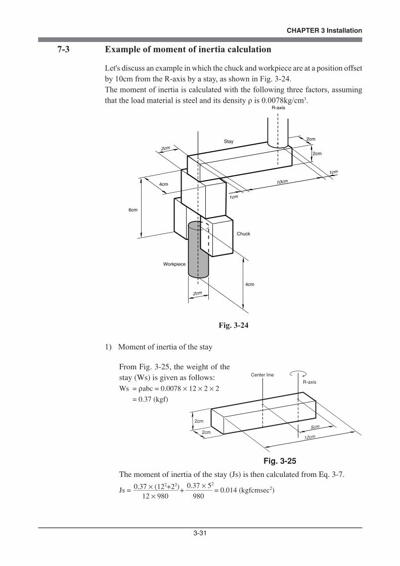
3-31
CHAPTER 3 Installation
7-3 Example of moment of inertia calculation
Let's discuss an example in which the chuck and workpiece are at a position offset by 10cm from the R-axis by a stay, as shown in Fig. 3-24.The moment of inertia is calculated with the following three factors, assuming that the load material is steel and its density ρ is 0.0078kg/cm3.
10cm
2cm
2cm
R-axis
1cm
1cm
2cm
2cm
4cm
6cm
4cm
Stay
Chuck
Workpiece
Fig. 3-24
1) Moment of inertia of the stay
From Fig. 3-25, the weight of thestay (Ws) is given as follows:Ws = ρabc = 0.0078 × 12 × 2 × 2 = 0.37 (kgf)
The moment of inertia of the stay (Js) is then calculated from Eq. 3-7.
Js = 0.37 × (122+22) +
0.37 × 52
= 0.014 (kgfcmsec2)12 × 980 980
Fig. 3-25
12cm
2cm
2cm
Center line
5cm
R-axis
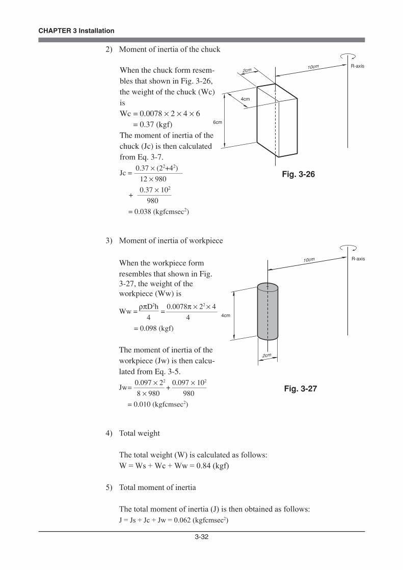
3-32
CHAPTER 3 Installation
2) Moment of inertia of the chuck
When the chuck form resem-bles that shown in Fig. 3-26,the weight of the chuck (Wc)isWc = 0.0078 × 2 × 4 × 6 = 0.37 (kgf)The moment of inertia of thechuck (Jc) is then calculatedfrom Eq. 3-7.
Jc = 0.37 × (22+42)
12 × 980 0.37 × 10²
+
980
= 0.038 (kgfcmsec2)
Fig. 3-26
10cm2cm
6cm
4cm
R-axis
3) Moment of inertia of workpiece
When the workpiece formresembles that shown in Fig.3-27, the weight of theworkpiece (Ww) is
Ww =ρπD2h
= 0.0078π × 22 × 4
4 4
= 0.098 (kgf)
The moment of inertia of theworkpiece (Jw) is then calcu-lated from Eq. 3-5.
Jw=0.097 × 22
+ 0.097 × 10²
8 × 980 980
= 0.010 (kgfcmsec2)
Fig. 3-27
10cm
4cm
R-axis
2cm
4) Total weight
The total weight (W) is calculated as follows: W = Ws + Wc + Ww = 0.84 (kgf)
5) Total moment of inertia
The total moment of inertia (J) is then obtained as follows: J = Js + Jc + Jw = 0.062 (kgfcmsec2)

3-33
CHAPTER 3 Installation
7-4 Attaching the end effector
The manipulator part to which an end effector is attached must have adequate strength and rigidity, as well as gripping force to prevent positioning errors. Table 3-1 shows the maximum load that can be applied to the end effector attachment of each robot model. Recommended methods for attaching end effectors are shown in Table 3-2 and Fig. 3-30. Refer to Fig. 3-28 for details on the end effector at-tachment of each robot model.When checking end effector operation, refer to "6 Trial Operation" in Chapter 1.
R6YXG120, R6YXG150,R6YXG180, R6YXG220
0-0.015
15
0-0.012
10
User tool installation range
Retaining ring to set the user tool
R6YXC120, R6YXC150 R6YXC180, R6YXC220
User tool installation range
Never loosen this bolt.
ø6 ø10 h7
-0.0210.000
12 (U
ser t
ool i
nsta
llatio
n ra
nge)
Plug
ø30 h7ø55
0.000+0.015
Depth: 2ø10 H7
User tapped hole4-M3x0.5, depth: 6
User tool installation tapped hole: 4-M3x0.5, depth: 6
Center line of user tool installation �ange is o�set ±5 or less withrespect to R-axis origin
16 245.3 5.3
5.3
5.3
2626
Fig. 3-28 Z-axis tip shape
Table 3-1
Robot Mode
R6YXC120
R6YXC150
N kgf N kgf N kgf Nm kgfm Nm kgfm
FXYmax FZmax FRmax MRmax Mmax
27
27
2.8
2.8
6.7
6.7
0.7
0.7
9.8
12
1.0
1.3
0.5
0.5
0.05
0.05
0.4
0.4
0.04
0.04
R6YXC180 27 2.8 6.7 0.7 15.7 1.6 4.5 0.46 0.9 0.09
R6YXG220, R6YXC220 30 3.1 6.7 0.7 18.6 1.9 4.5 0.46 0.9 0.09
R6YXG120 18 1.8 6.7 0.7 22.1 2.2 4.5 0.46 0.9 0.09
R6YXG150 23 2.3 6.7 0.7 22.1 2.2 4.5 0.46 0.9 0.09
R6YXG180 27 2.8 6.7 0.7 22.0 2.2 4.5 0.46 0.9 0.09
WARNINGBEFORE ATTACHING THE END EFFECTOR, BE SURE TO TURN OFF THE CONTROLLER.
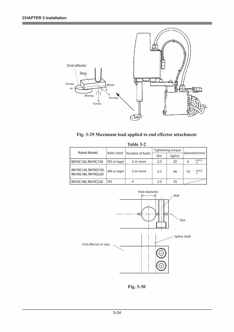
3-34
CHAPTER 3 Installation
End effector
Stay
FRmax
FxYmax
Mmax
Fzmax
MRmax
Fig. 3-29 Maximum load applied to end effector attachment
Table 3-2
Bolts Used Number of boltsNm kgfcm
M3 4 2.0 20 R6YXC180, R6YXC220
M3 or lager 2 or more 2.0 20 6
Tightening torquediameter(mm)
+0.012 0
M4 or lager
Robot ModeL
R6YXC120, R6YXC150
R6YXG120, R6YXG150, R6YXG180, R6YXG220
2 or more 4.5 46 10 +0.015 0
Hole diameterBolt
Slot
Spline shaft
End effector or stay
Fig. 3-30

3-35
CHAPTER 3 Installation
AxisR6YXC120, R6YXC150
X-axis
Y-axis
R-axis
Tolerable radial load
100N (10.2kgf)
45N (4.6kgf)
45N (4.6kgf)
Tolerable thrust load
100N (10.2kgf)
45N (4.6kgf)
45N (4.6kgf)
Tolerable moment load Tolerable torque
1.5Nm (15.3kgfcm)
0.45Nm (4.6kgfcm)
0.45Nm (4.6kgfcm)
1.7Nm (17.3kgfcm)
0.5Nm (5.1kgfcm)
0.3Nm (3.1kgfcm)
AxisR6YXG120, R6YXG150, R6YXG180, R6YXG220, R6YXC180, R6YXC220
X-axis
Y-axis
R-axis
Tolerable radial load
275N (28.1kgf)
150N (15.3kgf)
150N (15.3kgf)
Tolerable thrust load
900N (91.8kgf)
600N (61.2kgf)
600N (61.2kgf)
Tolerable moment load Tolerable torque
6.0Nm (61.2kgfcm)
3.3Nm (33.7kgfcm)
3.3Nm (33.7kgfcm)
9.0Nm (91.8kgfcm)
4.0Nm (40.8kgfcm)
2.2Nm (22.4kgfcm)
WARNINGTHE END EFFECTOR ATTACHMENT MUST HAVE ADEQUATE STRENGTH TO WITHSTAND THE LOADS LISTED IN TABLE 3-1. IF TOO WEAK, THE ATTACHMENT MAY BREAK DURING ROBOT OPERATION AND FRAGMENTS FLY OFF CAUSING ACCIDENTS OR INJURIES.
WARNINGTHE END EFFECTOR ATTACHMENT MUST HAVE SUFFICIENT RIGIDITY VERSUS THE LOADS LISTED IN TABLE 3-1. IF THIS RIGIDITY IS INADEQUATE, THE END EFFECTOR MAY VIBRATE DURING ROBOT OPERATION CAUSING BAD EFFECTS ON THE MANIPULATOR OPERATION.
WARNING• WHEN THE END EFFECTOR IS ATTACHED BY SLOT CLAMPING, ALWAYS OBSERVE THE CONDITIONS LISTED IN TABLE 3-2. IF THESE ARE IGNORED, THE END EFFECTOR MAY COME LOOSE AND FLY OFF DURING ROBOT OPERATION, RESULTING IN AN ACCIDENT OR INJURY. • IN CASES WHERE OTHER ATTACHMENT METHODS ARE USED, BE SURE THAT THE END EFFECTOR WILL NOT COME OFF WHEN THE LOADS LISTED IN TABLE 3-1 ARE APPLIED.
CAUTIONTHE XG SERIES (R6YXG120, R6YXG150, R6YXG180, R6YXG220) AND XC SERIES (R6YXC120, R6YXC150, R6YXC180, R6YXC220) ARE DESIGNED TO BE COMPACT, SO THE JOINTS COULD BE DAMAGED IF E X C E S S I V E F O R C E I S A P P L I E D , F O R E X A M P L E , D U R I N G INSTALLATION OF AN END EFFECTOR. MAKE SURE THAT EXCESSIVE FORCE IS NOT APPLIED TO THE JOINTS.
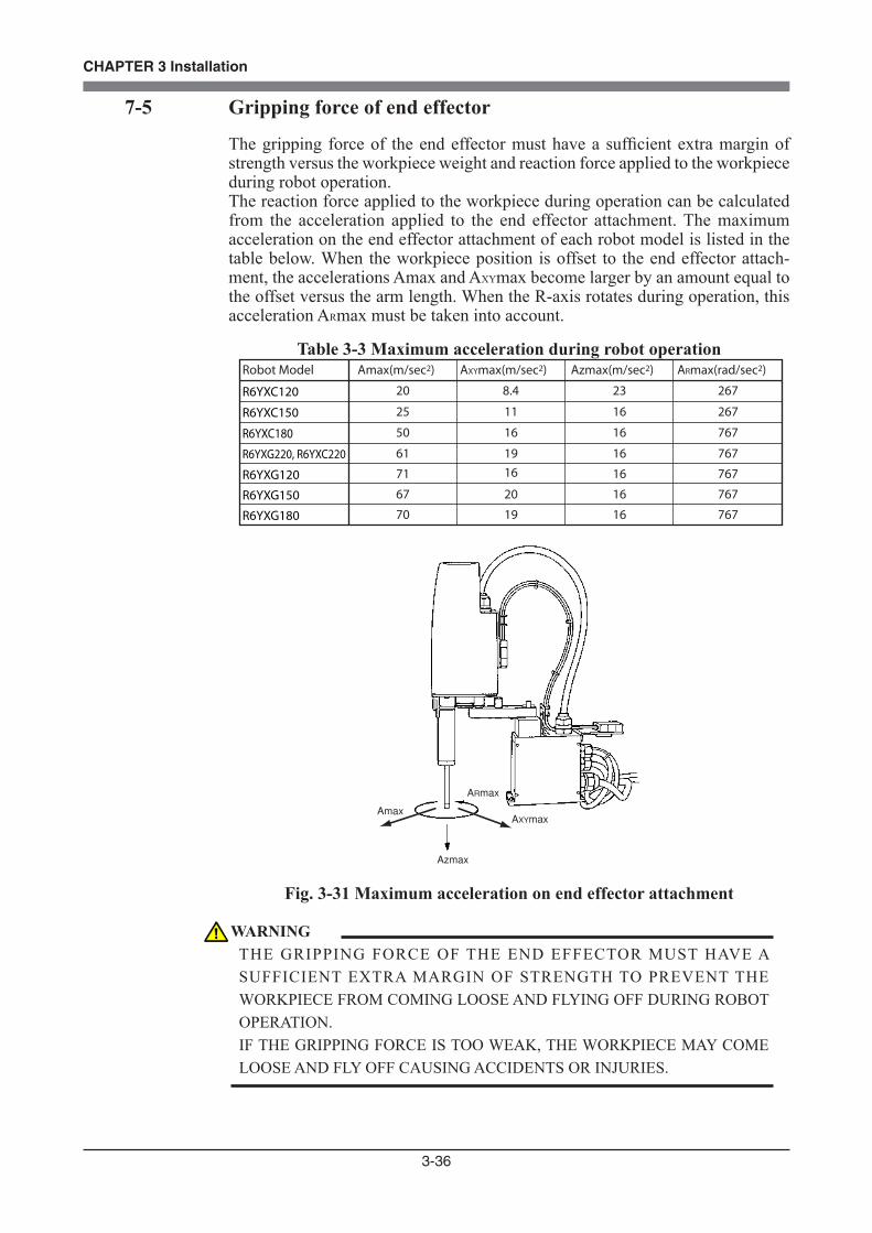
3-36
CHAPTER 3 Installation
7-5 Gripping force of end effector
The gripping force of the end effector must have a sufficient extra margin of strength versus the workpiece weight and reaction force applied to the workpiece during robot operation.The reaction force applied to the workpiece during operation can be calculated from the acceleration applied to the end effector attachment. The maximum acceleration on the end effector attachment of each robot model is listed in the table below. When the workpiece position is offset to the end effector attach-ment, the accelerations Amax and AXYmax become larger by an amount equal to the offset versus the arm length. When the R-axis rotates during operation, this acceleration ARmax must be taken into account.
Table 3-3 Maximum acceleration during robot operationRobot Model
R6YXC120
R6YXC150
Amax(m/sec2) AXYmax(m/sec2) Azmax(m/sec2) ARmax(rad/sec2)
20 8.4 23 267
25 11 16 267
R6YXC180 50 16 16 767
R6YXG220, R6YXC220 61 19 16 767
R6YXG120 71 16 767
R6YXG150 67 20 16 767
R6YXG180 70 19 16 767
16
ARmax
Amax
Azmax
AXYmax
Fig. 3-31 Maximum acceleration on end effector attachment
WARNINGTHE GRIPPING FORCE OF THE END EFFECTOR MUST HAVE A SUFFICIENT EXTRA MARGIN OF STRENGTH TO PREVENT THE WORKPIECE FROM COMING LOOSE AND FLYING OFF DURING ROBOT OPERATION. IF THE GRIPPING FORCE IS TOO WEAK, THE WORKPIECE MAY COME LOOSE AND FLY OFF CAUSING ACCIDENTS OR INJURIES.
3-37
CHAPTER 3 Installation
8 Working Envelope and Mechanical Stopper Positions for Maximum Working EnvelopeWorking envelope and mechanical stopper positions for the maximum working envelope of each robot are shown in "1-2 External view and dimensions" in Chapter 7.An example using the R6YXC120 is described below. (Refer to Fig. 7-1.) Other robot models are the same.
1) X and Y axesDo not attempt operation outside the working envelope. The working envelope described in this manual is an area with the robot frontal reference.
2) Z-axisDo not attempt work outside the working envelope. In particular, do not attempt work in the area between the working envelope and mechanical stopper position. Mechanical stoppers are installed at both the upper and lower ends of the movement range.
3) R-axisThe R-axis has no mechanical stoppers.
4) Robot overrun during impacts with mechanical stopperA urethane damper is installed to absorb the shock when an impact occurs with the mechanical stopper, so a certain amount of overrun occurs when the robot strikes the mechanical stopper. Use caution and take overrun into account since the end effector may interfere with the robot body and peripheral equipment or the robot body may interfere with the peripheral equipment. Maximum overrun amounts are listed below (for normal operation, maximum payload, maximum speed).
4mm
Lower end
2mm
Upper end
Z-axis
5°
Y-axis
6°
X-axis
Note: Here,° (deg.) is the overrun angle at the X-axis and Y-axis joints.
All models
WARNINGTHE ROBOT CABLE, USER WIRING OR TUBING MAY BE DAMAGED IF THE ROBOT LOAD INTERFERES WITH THEM RESULTING IN HAZARDOUS ROBOT MALFUNCTIONS. DO NOT OPERATE AT POINTS WHERE THE LOAD MAY INTERFERE WITH THE ROBOT CABLE, USER WIRING OR TUBING.
CAUTIONSINCE THE R-AXIS HAS NO MECHANICAL STOPPERS, MAKE CERTAIN THAT THE END EFFECTOR WIRING AND TUBING DO NOT BECOME ENTANGLED DURING OPERATION.
3-38
CHAPTER 3 Installation
(1) If the X-axis, Y-axis or Z-axis mechanical stopper is deformed or damaged by impacts, please contact our sales office or dealer. Using the deformed or damaged mechanical stopper is dangerous, so it must be replaced.
(2) When the robot strikes the X-axis or Y-axis mechanical stopper or another object, or when the R-axis collides with an object, speed reduction gears are locked while being meshed if the collision impact is large. If this happens, please contact our sales office or dealer.
(3) After the robot strikes the Z-axis mechanical stopper, the stopper position may shift, and so check the stopper position. If shifted, move the stopper to the correct position and refasten it securely by following the assembly procedure.

3-39
CHAPTER 3 Installation
9 Stopping Time and Stopping Distance at Emergency Stop
9-1 R6YXG220, R6YXC180, R6YXC220When the emergency stop button is pressed during robot operation or the power supply to the controller is turned off, the stopping time and stopping distance or angle of the main 3 axes change depending on the operation speed as shown below. The following figures show typical time and distance or angle needed for each axis to come to a stop after a stop signal is initiated when the robot arms are fully extended while 3 types of tip mass (33%, 66% and 100% of maximum payload) are loaded.
0
0.02
0.04
0.06
0.08
0.1
0.12
0.14
0.16
0.18
0.3
0.2
0.22
0.24
0.28
0.26
0 10 20 30 40 50 60 70 80 90 100
Operation speed (%)
XY-
axis
sto
ppin
g tim
e (s
ec.)
Tip load mass 0.33kgTip load mass 0.66kgTip load mass 1kg
Fig. 3-32 XY-axis stopping time for R6YXC180
0
10
20
30
40
50
60
70
80
90
100
110
0 10 20 30 40 50 60 70 80 90 100Operation speed (%)
XY-
arm
sto
ppin
g ro
tatio
n an
gle
(°) Tip load mass 0.33kg_X arm
Tip load mass 0.33kg_Y armTip load mass 0.66kg_X armTip load mass 0.66kg_Y armTip load mass 1kg_X armTip load mass 1kg_Y arm
Fig. 3-33 XY-arm stopping rotation angle for R6YXC180
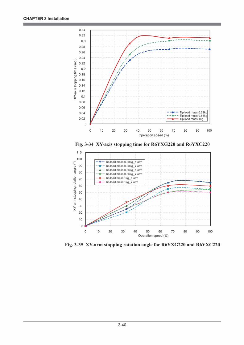
3-40
CHAPTER 3 Installation
0
0.02
0.04
0.06
0.08
0.1
0.12
0.14
0.16
0.18
0.3
0.2
0.22
0.24
0.28
0.26
0 10 20 30 40 50 60 70 80 90 100
Operation speed (%)
XY-
axis
sto
ppin
g tim
e (s
ec.)
Tip load mass 0.33kgTip load mass 0.66kgTip load mass 1kg
0.34
0.32
Fig. 3-34 XY-axis stopping time for R6YXG220 and R6YXC220
0
10
20
30
40
50
60
70
80
90
100
110
0 10 20 30 40 50 60 70 80 90 100Operation speed (%)
XY-
arm
sto
ppin
g ro
tatio
n an
gle
(°) Tip load mass 0.33kg_X arm
Tip load mass 0.33kg_Y armTip load mass 0.66kg_X armTip load mass 0.66kg_Y armTip load mass 1kg_X armTip load mass 1kg_Y arm
Fig. 3-35 XY-arm stopping rotation angle for R6YXG220 and R6YXC220

3-41
CHAPTER 3 Installation
0
0.01
0.02
0.03
0.04
0.05
0 10 20 30 40 50 60 70 80 90 100Operation speed (%)
Z-
axis
sto
ppin
g tim
e (s
ec.)
Tip load mass 0.33kgTip load mass 0.66kgTip load mass 1kg
All plotted lines are overlapped.
Fig. 3-36 Z-axis stopping time for R6YXG220, R6YXC180 and R6YXC220
0
1
2
3
4
5
6
7
8
9
15
10
11
12
14
13
0 10 20 30 40 50 60 70 80 90 100
Operation speed (%)
Z-a
xis
stop
ping
dis
tanc
e (m
m)
Tip load mass 0.33kgTip load mass 0.66kgTip load mass 1kg
Plotted lines for 0.33kg and 0.66kg are overlapped.
Fig. 3-37 Z-axis stopping distance for R6YXG220, R6YXC180 and R6YXC220
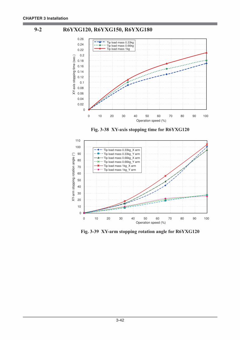
3-42
CHAPTER 3 Installation
9-2 R6YXG120, R6YXG150, R6YXG180
0
0.02
0.04
0.06
0.08
0.1
0.12
0.14
0.16
0.18
0.2
0.22
0.24
0.26
0 10 20 30 40 50 60 70 80 90 100
Operation speed (%)
XY-
axis
sto
ppin
g tim
e (s
ec.)
Tip load mass 0.33kgTip load mass 0.66kgTip load mass 1kg
Fig. 3-38 XY-axis stopping time for R6YXG120
0
10
20
30
40
50
60
70
80
90
100
110
0 10 20 30 40 50 60 70 80 90 100Operation speed (%)
XY-
arm
sto
ppin
g ro
tatio
n an
gle
(°)
Tip load mass 0.33kg_X armTip load mass 0.33kg_Y armTip load mass 0.66kg_X armTip load mass 0.66kg_Y armTip load mass 1kg_X armTip load mass 1kg_Y arm
Fig. 3-39 XY-arm stopping rotation angle for R6YXG120
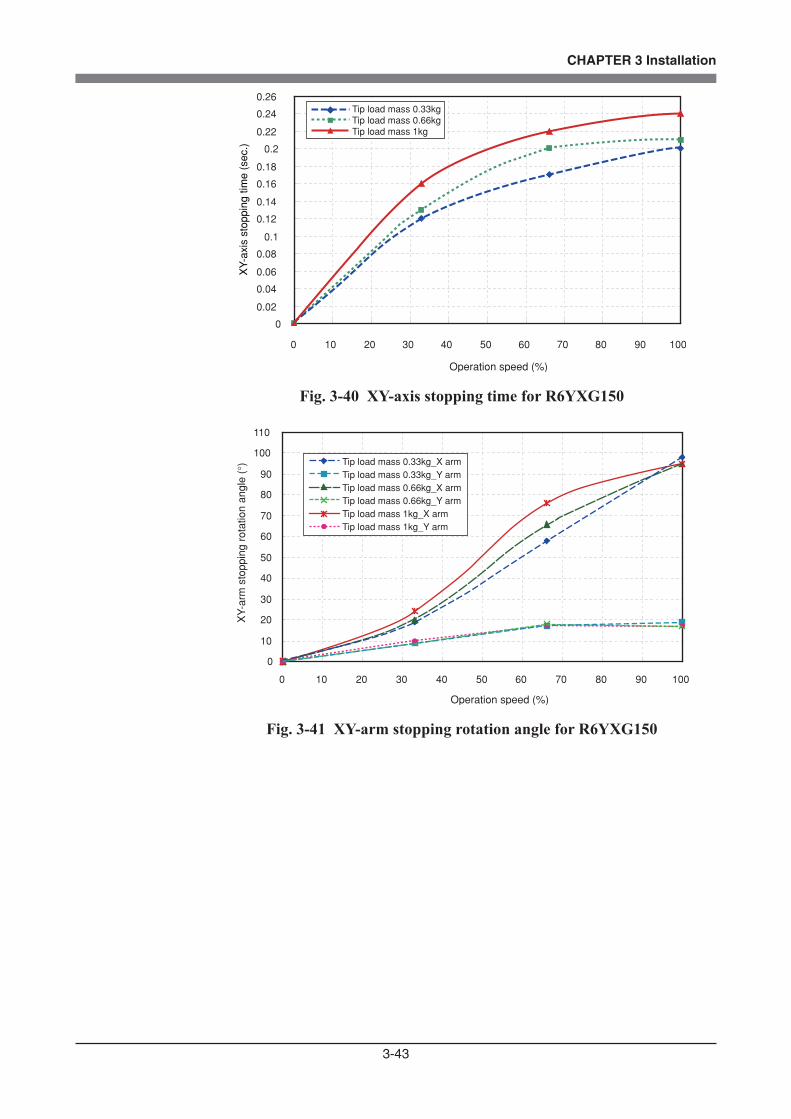
3-43
CHAPTER 3 Installation
0
0.02
0.04
0.06
0.08
0.1
0.12
0.14
0.16
0.18
0.2
0.22
0.24
0.26
0 10 20 30 40 50 60 70 80 90 100
Operation speed (%)
XY-
axis
sto
ppin
g tim
e (s
ec.)
Tip load mass 0.33kgTip load mass 0.66kgTip load mass 1kg
Fig. 3-40 XY-axis stopping time for R6YXG150
0
10
20
30
40
50
60
70
80
90
100
110
0 10 20 30 40 50 60 70 80 90 100
Operation speed (%)
XY-
arm
sto
ppin
g ro
tatio
n an
gle
(°) Tip load mass 0.33kg_X arm
Tip load mass 0.33kg_Y armTip load mass 0.66kg_X armTip load mass 0.66kg_Y armTip load mass 1kg_X armTip load mass 1kg_Y arm
Fig. 3-41 XY-arm stopping rotation angle for R6YXG150
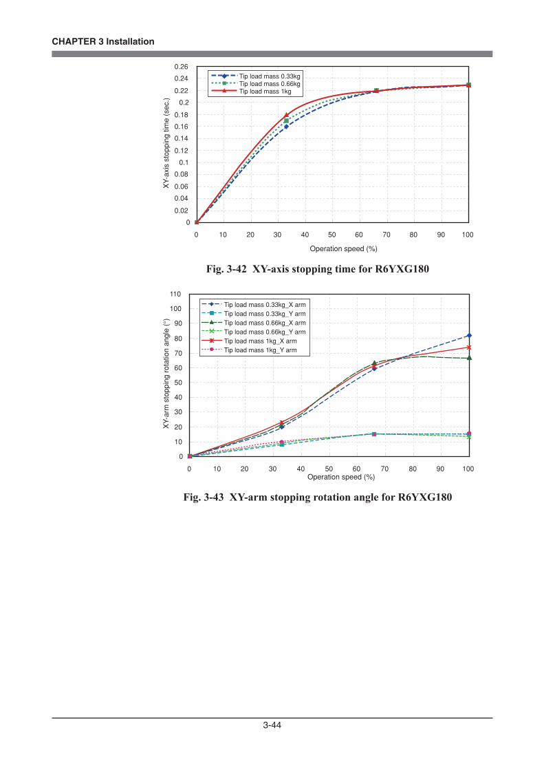
3-44
CHAPTER 3 Installation
0
0.02
0.04
0.06
0.08
0.1
0.12
0.14
0.16
0.18
0.2
0.22
0.24
0.26
0 10 20 30 40 50 60 70 80 90 100
Operation speed (%)
XY-
axis
sto
ppin
g tim
e (s
ec.)
Tip load mass 0.33kgTip load mass 0.66kgTip load mass 1kg
Fig. 3-42 XY-axis stopping time for R6YXG180
0
10
20
30
40
50
60
70
80
90
100
110
0 10 20 30 40 50 60 70 80 90 100Operation speed (%)
XY-
arm
sto
ppin
g ro
tatio
n an
gle
(°)
Tip load mass 0.33kg_X armTip load mass 0.33kg_Y armTip load mass 0.66kg_X armTip load mass 0.66kg_Y armTip load mass 1kg_X armTip load mass 1kg_Y arm
Fig. 3-43 XY-arm stopping rotation angle for R6YXG180

3-45
CHAPTER 3 Installation
0
0.01
0.02
0.03
0.04
0.05
0 10 20 30 40 50 60 70 80 90 100Operation speed (%)
Z-
axis
sto
ppin
g tim
e (s
ec.)
Tip load mass 0.33kgTip load mass 0.66kgTip load mass 1kg
Fig. 3-44 Z-axis stopping time for R6YXG120, R6YXG150 and R6YXG180
0
0.5
1
1.5
2
2.5
3
3.5
4
4.5
5
0 10 20 30 40 50 60 70 80 90 100
Operation speed (%)
Z-a
xis
stop
ping
dis
tanc
e (m
m)
Tip load mass 0.33kg
Tip load mass 0.66kg
Tip load mass 1kg
Fig. 3-45 Z-axis stopping distance for R6YXG120, R6YXG150 and R6YXG180

3-46
CHAPTER 3 Installation
10 When Attaching a New User Wire or Tube
10-1 R6YXC120, R6YXC150, R6YXG120, R6YXG150, R6YXG180, R6YXG220 robotsIf the number of the pre-installed user wires or tubes is not sufficient, add a new user wire or tube as needed to the pre-installed wires and tubes, and bundle them together with cable ties as shown in Fig. 3-46.Up to two ø4 wires or tubes can be added. Do not add more than two wires or tubes to ensure durability.When attaching the wires or tubes, refer to Fig. 3-46 below and follow the notes.
Recommended new user wire: For durability, use OMRON cables with ø4 urethane tube containing wires.
KCB-M489A-001 CABLE, CABTYRE
234050 50
Conductor wire
Recommended new air tube: φ 4 urethane tube
Pre-installed user wires and tubes (4 pieces)
New user wire or tube
New user wire or tube
Urethane tube φ 4
Use 5 or 6 cable ties to uniformly bundle the wires and tubes together. Tighten the cable ties just enough to hold the wires and tubes, but not enough to deform the air tubes.Overtightening may cause a drop in air flow and/or open-circuit fault in the cable.
Allowable voltage 30VAllowable current 1.5ANominal conductor cross-sectional area 0.1mm2
Insulator ETFENumber of conductor wires 4 (red, white, yellow, blue)Shield None
(Note)
Fig. 3-46
3-47
CHAPTER 3 Installation
10-2 R6YXC180, R6YXC220 robots
If the number of the pre-installed user wires or tubes is not sufficient, add a new user wire or tube as needed to the machine harness, and bundle them together with cable ties.Up to two ø4 wires or tubes can be added. Do not add more than two wires or tubes to ensure durability.When bundling the wires and tubes with cable ties, follow the notes in Fig. 3-46.
Recommended new user wire: For durability, use OMRON cables with ø4 urethane tube containing wires.
KCB-M489A-001 CABLE, CABTYRE

3-48
CHAPTER 3 Installation
11 Installing the additional mechanical stopper
11-1 R6YXG220
11-1-1 Installing the X-, Y- and Z-axis additional mechanical stoppers
The X-, Y- and Z-axis movement ranges can be narrowed as shown in Table 3-5 by ordering and installing additional optional parts listed in Table 3-4. The mechanical stopper positions may slightly differ depending on machining precision of the parts and the installation position.
Table 3-4No.
q
w
e
r
y
r
t
w
q
QtyPart No. Remarks
Additional mechanical stopper parts in
Y-axis minus direction
Additional mechanical stopper parts in
X-axis minus direction
Additional mechanical stopper parts in
Y-axis plus direction
Additional mechanical stopper parts in
X-axis plus direction
1KBE-M2124-000
291312-05014
Stopper block
Bolt
1
KBE-M2585-100
KBE-M2588-000
91312-04045
91312-05014
KBE-M2587-000
Y-axis dog(*1)
Stopper block
Bolt
Bolt
Stopper block
2
1
2
1
1
1
91312-04045
KBE-M2124-000
Bolt
Stopper block
*1: The Y-axis dog must be changed when adding the mechanical stopper in the Y-axis minus direction. The Y-axis origin position is also changed as shown in Fig. 3-47.
No.
q
e
w
Qty Part No. Remarks
Additional mechanical stopper parts in
Z-axis plus direction
KCB-M183A-000Stopper block
(supplied with bolt)
1
1
2
KBE-M1780-000
91312-04012
Stopper block
Bolt
Additional mechanical stopper parts in
Z-axis minus direction
WARNINGALWAYS TURN OFF THE CONTROLLER BEFORE CHANGING THE MOVEMENT RANGE WITH MECHANICAL STOPPERS.
CAUTIONWHEN THE MECHANICAL STOPPERS ARE INSTALLED, THE SOFT LIMITS MUST BE SET TO A POINT INSIDE THE MECHANICAL STOPPER POSITIONS.
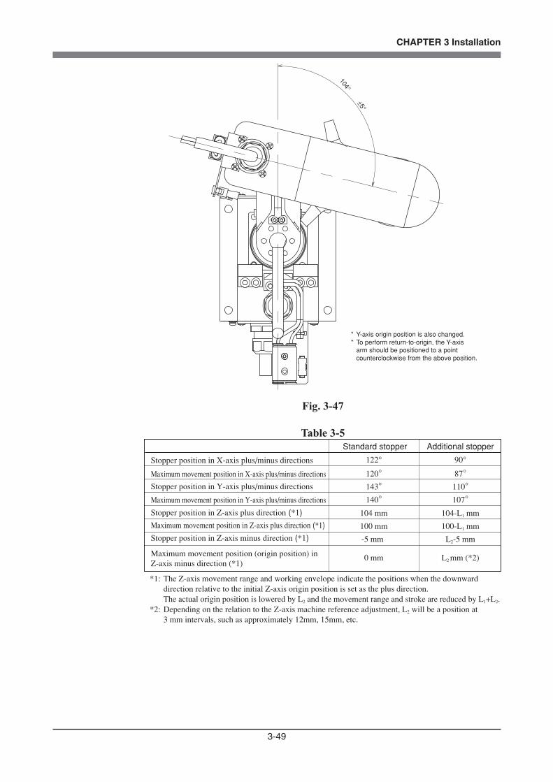
3-49
CHAPTER 3 Installation
104°
±5°
* Y-axis origin position is also changed.* To perform return-to-origin, the Y-axis arm should be positioned to a point counterclockwise from the above position.
Fig. 3-47
Table 3-5 Standard stopper Additional stopper
Stopper position in X-axis plus/minus directions
Maximum movement position in X-axis plus/minus directions
Stopper position in Y-axis plus/minus directions
Maximum movement position in Y-axis plus/minus directions
Stopper position in Z-axis plus direction (*1)
Maximum movement position in Z-axis plus direction (*1)
Stopper position in Z-axis minus direction (*1)
Maximum movement position (origin position) in Z-axis minus direction (*1)
122°
120°
143°
140°
104 mm
100 mm
-5 mm
0 mm
90°
87°
110°
107°
104-L1 mm
100-L1 mm
L2-5 mm
L2 mm (*2)
*1: The Z-axis movement range and working envelope indicate the positions when the downward direction relative to the initial Z-axis origin position is set as the plus direction. The actual origin position is lowered by L2 and the movement range and stroke are reduced by L1+L2.*2: Depending on the relation to the Z-axis machine reference adjustment, L2 will be a position at 3 mm intervals, such as approximately 12mm, 15mm, etc.
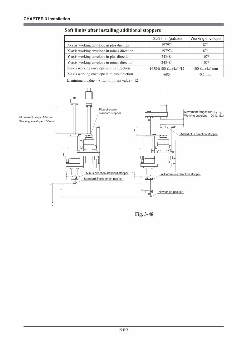
3-50
CHAPTER 3 Installation
Soft limits after installing additional stoppers Soft limit (pulses) Working envelope
X-axis working envelope in plus direction
X-axis working envelope in minus direction
Y-axis working envelope in plus direction
Y-axis working envelope in minus direction
Z-axis working envelope in plus direction
Z-axis working envelope in minus direction
197974
-197974
243484
-243484
16384(100-(L1+L2))/12
-683
87°
-87°107°
-107°100-(L1+L2) mm
-0.5 mm
L1 minimum value = 8, L2 minimum value = 12
Movement range: 104mmWorking envelope: 100mm
Plus direction standard stopper
5 Minus direction standard stopper
Standard Z-axis origin position
L2
0
+
New origin position
Added minus direction stopper
L2
5L1
Movement range: 104-(L1+L2)Working envelope: 100-(L1+L2)
Added plus direction stopper
Fig. 3-48

3-51
CHAPTER 3 Installation
11-1-2 Installing the X- and Y-axis additional mechanical stoppers
Install the X- and Y-axis additional mechanical stoppers by following the instructions shown in Fig. 3-49. The X and Y-axis mechanical stoppers can be installed separately in the plus and minus directions. Fig. 3-49 shows an exam-ple for installing the additional stopper as the minus direction stopper, but the stopper can also be installed in the plus direction. Replace the Y-axis dog only when adding the stopper in the Y-axis minus direction.The following procedure is described using the Y-axis minus direction stopper as an example.
1) Prepare the hex wrench set and torque wrench.
2) Turn off the robot controller.
3) Place a sign indicating the robot is being adjusted, to keep others from touching the controller switch.
4) Enter the safeguard enclosure.
5) Secure the stopper block 5 to the Y-axis arm by tightening the bolt 4 to the specified torque. Use the bolts shown in Table 3-4.
6) Remove the bolt and washer used to secure the Y-axis dog and remove the dog. Then secure the dog 6 with the bolt and washer removed, by tightening the bolt to the specified torque. (This step is required only when the stopper is added in the Y-axis minus direction.)
7) Check that the movement range is limited by the stoppers as desired.
8) Check that the Y-axis sensor does not interfere with the dog. (This is required only when the stopper is added in the Y-axis minus direction.)
9) Go out of the safeguard enclosure.
10) Check that no one is inside the safeguard enclosure and then turn on the controller.
11) Set the soft limit in the Y-axis minus direction as shown in Table 3-5. (When the stopper was installed in the plus direction, set the soft limit in the plus direction.)
12) Adjust the Y-axis machine reference value by referring to section 3-4-2-3 in Chapter 4. (This step is required only when the stopper is added in the Y-axis minus direction.)
13) Stay outside the safeguard enclosure and check that the soft limits work to stop the Y-axis arm at a point before the stopper position. Depending on the accuracy and position of the stopper parts, the Y-axis arm may not stop until it reaches the stopper. In this case, set the soft limits smaller than the values shown in Table 3-5.

3-52
CHAPTER 3 Installation
-
wTightening torque: 9Nm (90kgfcm)
Tightening torque: 2Nm (20kgfcm)
q
* Reuse this bolt and washer.* Reuse this bolt and washer.
X-axis stopper
Remove the dog.
Remove the tapped-hole plug screws.
t
r
Tightening torque: 4.5Nm (46kgfcm)
Y-axis stopper
Plus direction
* The above is an example of adding the minus direction stopper. When installing the stopper in the plus direction, install it on the opposite side.
Replace only when the stopper is added in the Y-axis minus direction.
y
Y-axis dog(only when adding the stopper the Y-axis minus direction)
Minus direction
Fig. 3-49
The M4 tapped holes in the Y-axis stopper block can also be used to attach a tool as shown in Fig. 3-50. The Y-axis stopper block projects a distance from the Y-axis arm as shown in Fig. 3-50.
3512
8
Do not screw the screws in deeper than 6mm from the stopper block surface.The weight of the tool attached here should be added to the tip mass.
2-M4x0.7 tapped holes for attaching tool
70
577077
99.8
90.7
R10
Y-axis additional stopper
Center of R-axis
Fig. 3-50

3-53
CHAPTER 3 Installation
11-1-3 Installing the additional mechanical stopper in the Z-axis minus direction
Install the additional mechanical stopper in the Z-axis minus direction by following the instructions shown in Fig. 3-51.
1) Prepare the hex wrench set and torque wrench.
2) Turn off the robot controller.
3) Place a sign indicating the robot is being adjusted, to keep others from touching the controller switch.
4) Enter the safeguard enclosure.
5) Remove the Y-axis arm cover by referring to section 7 in Chapter 4, and move up the urethane damper.
6) Install the additional stopper 3 to the spline shaft by tightening the supplied bolts to the specified torque. Alternately tighten the bolts a little at a time. Depending on the relation to the Z-axis machine reference adjustment, L2 in the Z-axis minus direction stopper in Table 3-6 will be a position at 3 mm intervals, such as approximately 12mm, 15mm, etc.
7) Go out of the safeguard enclosure.
8) Check that no one is inside the safeguard enclosure, and then turn on the controller.
9) Place a sign indicating the robot is being adjusted, to keep others from operating the controller or operation panel.
10) Perform the Z-axis absolute reset. To perform the Z-axis absolute reset, see "3-3 Absolute reset procedures" in
Chapter 4. Make a note of the Z-axis machine reference value.
(1) Press the MODE key.(2) Press the F3 key to enter MANUAL mode.(3) Press the F13 key (LOWER+F3) to select "ABS Reset".(4) After the Z-axis absolute reset is complete, press the F10 (UPPER+F5) key
to display the adjustment machine reference value (%).
WARNINGUSE THE FOLLOWING PROCEDURE TO DISPLAY THE ADJUSTMENT MACHINE REFERENCE VALUE. WHEN ADJUSTING THE MACHINE REFERENCE VALUE, ALWAYS CHECK THE ADJUSTMENT MACHINE REFERENCE VALUE WITH THIS PROCEDURE.

3-54
CHAPTER 3 Installation
When the machine reference is within the allowable range (between 26 and 74%), proceed to step 16). If the machine reference is outside the allowable range, adjust it as described in step 11) onward.
11) Turn off the controller and enter the safeguard enclosure.
12) Put a mark at the added stopper position and loosen the bolt for the added stopper.
To adjust the machine reference value, move the added stopper as follows: Machine reference value < 26% : Move the added stopper in the plus direction. Machine reference value > 74% : Move the added stopper in the minus direction. As an approximate guide, a 3mm movement equals 100%.
13) Repeat the same procedure from step 6) until the machine reference is within the allowable range.
14) When the machine reference is set within the allowable range, go out of the safeguard enclosure.
15) Check that no one is inside the safeguard enclosure and then turn on the controller.
16) Set the soft limits as shown in Table 3-5. The soft limit in the minus direction is already set by default to the value
shown in Table 3-5.
17) Stay outside the safeguard enclosure and check that the soft limits work to stop the Z-axis unit at a point before the stopper position. Depending on the accuracy and position of the stopper parts, the Z-axis unit may not stop until it reaches the stopper. In this case, set the soft limits larger than the values shown in Table 3-5.
18) Check that the movement range is limited by the stoppers as desired.
19) Turn off the controller and enter the safeguard enclosure.
20) Reattach the Y-axis arm cover.

3-55
CHAPTER 3 Installation
Bolt supplied with eTightening torque: 4.5Nm (46kgfcm)
Minus direction stopper
qwTightening torque: 4.5Nm (46kgfcm)
Plus direction stopperMove up the urethane damper.
Minus direction
Plus direction
Move up the urethane damper.
e
Fig. 3-51

3-56
CHAPTER 3 Installation
11-1-4 Installing the additional mechanical stopper in the Z-axis plus direction
Install the additional mechanical stopper in the Z-axis plus direction by following the instructions shown in Fig. 3-51.
1) Prepare the hex wrench set and torque wrench.
2) Turn off the robot controller.
3) Place a sign indicating the robot is being adjusted, to keep others from touching the controller switch.
4) Enter the safeguard enclosure.
5) Remove the Y-axis arm cover by referring to section 7 in Chapter 4, and move up the urethane damper.
6) Install the additional stopper 1 to the ball screw by tightening the bolts 2 to the specified torque.
Alternately tighten the bolts a little at a time. There is no restriction on the stopper position in the plus direction.
7) Go out of the safeguard enclosure.
8) Check that no one is inside the safeguard enclosure, and then turn on the controller.
9) Place a sign indicating the robot is being adjusted, to keep others from operating the controller or operation panel.
10) Set the soft limit in the plus direction as shown in Table 3-5.
11) Stay outside the safeguard enclosure and check that the soft limits work to stop the Z-axis unit at a point before the stopper position.
Depending on the accuracy and position of the stopper parts, the Z-axis unit may not stop until it reaches the stopper. In this case, set the soft limits smaller than the values shown in Table 3-5.
12) Check that the movement range is limited by the stoppers as desired.
13) Turn off the controller and enter the safeguard enclosure.
14) Reattach the Y-axis arm cover.
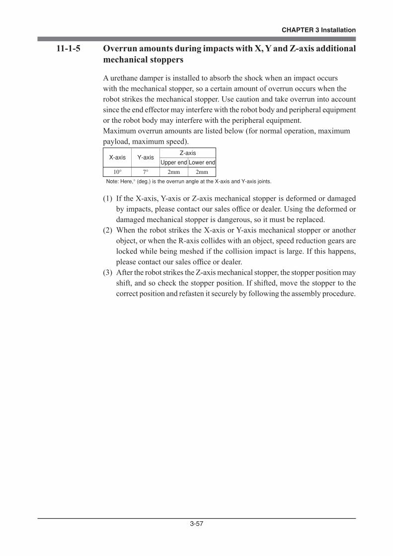
3-57
CHAPTER 3 Installation
11-1-5 Overrun amounts during impacts with X, Y and Z-axis additional mechanical stoppers
A urethane damper is installed to absorb the shock when an impact occurswith the mechanical stopper, so a certain amount of overrun occurs when therobot strikes the mechanical stopper. Use caution and take overrun into account since the end effector may interfere with the robot body and peripheral equipment or the robot body may interfere with the peripheral equipment.Maximum overrun amounts are listed below (for normal operation, maximumpayload, maximum speed).
2mm
Lower end
2mm
Upper end
Z-axis
7°
Y-axis
10°
X-axis
Note: Here,° (deg.) is the overrun angle at the X-axis and Y-axis joints.
(1) If the X-axis, Y-axis or Z-axis mechanical stopper is deformed or damaged by impacts, please contact our sales office or dealer. Using the deformed or damaged mechanical stopper is dangerous, so it must be replaced.
(2) When the robot strikes the X-axis or Y-axis mechanical stopper or another object, or when the R-axis collides with an object, speed reduction gears are locked while being meshed if the collision impact is large. If this happens, please contact our sales office or dealer.
(3) After the robot strikes the Z-axis mechanical stopper, the stopper position may shift, and so check the stopper position. If shifted, move the stopper to the correct position and refasten it securely by following the assembly procedure.

3-58
CHAPTER 3 Installation
11-2 R6YXG120, R6YXG150, R6YXG180
11-2-1 Installing the X, Y and Z-axis additional mechanical stoppers
The X, Y and Z-axis movement ranges can be narrowed as shown in Table 3-7 by ordering and installing additional optional parts listed in Table 3-6. The mechanical stopper positions may slightly differ depending on machining precision of the parts and the installation position.
Table 3-6
No.1
2
6 1KBE-M2596-001 Stopper damper
3
4
5 91312-03045 Bolt2
8
6 KBE-M2596-001 Stopper damper1
3
2
7
5
QtyPart No . Remarks
Additional mechanical stopper parts in X-axis plus direction
Additional mechanical stopper parts in X-axis minus direction
Additional mechanical stopper parts in Y-axis minus direction
Additional mechanical stopper parts in Y-axis plus direction
1KCB-M2125-010
1KCB-M2512-010
Stopper block
Stopper damper
1
KCB-M2588-000
KCB-M2512-010
91312-05010
KCB-M2124-010
91312-05010
Stopper block
Stopper damper
Bolt
Stopper block
Bolt
1
1
1
1
1
2
KCB-M2587-000
91312-03045
Stopper block
Bolt
R6YXG120
No.1
2
3
4
6 KBE-M2596-001 Stopper damper1
5 91312-03045 Bolt2
8 KCB-M2588-000 Stopper block1
3
2
7
6
5
QtyPart No . Remarks
Additional mechanical stopper parts in Y-axis plus direction
Additional mechanical stopper parts in X-axis plus direction
Additional mechanical stopper parts in Y-axis minus direction
Additional mechanical stopper parts in X-axis minus direction
1KCB-M2125-010
1KCB-M2512-010
Stopper block
Stopper damper
1
91312-05010
KCB-M2124-010
KCB-M2512-010
KBE-M2596-001
91312-05010
Bolt
Stopper block
Stopper damper
Stopper damper
Bolt
1
1
1
1
1
2
KCB-M2587-000
91312-03045
Stopper block
Bolt
R6YXG150
WARNINGALWAYS TURN OFF THE CONTROLLER BEFORE CHANGING THE MOVEMENT RANGE WITH MECHANICAL STOPPERS.
CAUTIONWHEN THE MECHANICAL STOPPERS ARE INSTALLED, THE SOFT LIMITS MUST BE SET TO A POINT INSIDE THE MECHANICAL STOPPER POSITIONS.

3-59
CHAPTER 3 Installation
No.1
2
6 1KBE-M2596-001 Stopper damper
3
4
6 KBE-M2596-001 Stopper damper1
5 91312-03045 Bolt2
8 KCB-M2588-000 Stopper block1
6 KBE-M2596-001 Stopper damper1
3
2
7
6
5
QtyPart No . Remarks
Additional mechanical stopper parts in Y-axis plus direction
Additional mechanical stopper parts in X-axis plus direction
Additional mechanical stopper parts in Y-axis minus direction
Additional mechanical stopper parts in X-axis minus direction
1KCB-M2125-010
1KCB-M2512-010
Stopper block
Stopper damper
1
91312-05010
KCB-M2124-010
KCB-M2512-010
KBE-M2596-001
91312-05010
Bolt
Stopper block
Stopper damper
Stopper damper
Bolt
1
1
1
1
1
2
KCB-M2587-000
91312-03045
Stopper block
Bolt
R6YXG180
No.1
3
2
Qty Part No . Remarks
Additional mechanical stopper parts in Z-axis plus direction
KCB-M183A-000Stopper block (supplied with bolt)
1
1
2
KCB-M1780-000
91312-03010
Stopper block
Bolt
Additional mechanical stopper parts in Z-axis minus direction
Table 3-7 Standard stopper Additional stopper
Stopper position in X-axis plus/minus directions
Maximum movement position in X-axis plus/minus directions
Stopper position in Y-axis plus/minus directions
Maximum movement position in Y-axis plus/minus directions
Stopper position in Z-axis plus direction (*1)
Maximum movement position in Z-axis plus direction (*1)
Stopper position in Z-axis minus direction (*1)
Maximum movement position (origin position) in Z-axis minus direction (*1)
128°
125°
148°
145°
53 mm
50 mm
-3 mm
0 mm
90°
87°
90°
87°
53-L1 mm
50-L1 mm
L2-3 mm
L2 mm (*2)
*1: The Z-axis movement range and working envelope indicate the positions when the downward direction relative to the initial Z-axis origin position is set as the plus direction. The actual origin position is lowered by L2 and the movement range and stroke are reduced by L1+L2.*2: Depending on the relation to the Z-axis machine reference adjustment, L2 will be a position of approximately 12, 24, 36 or 48mm.
Soft limits after installing additional stoppers Soft limit (pulses) Working envelope
X-axis working envelope in plus direction
X-axis working envelope in minus direction
Y-axis working envelope in plus direction
Y-axis working envelope in minus direction
Z-axis working envelope in plus direction
Z-axis working envelope in minus direction
197974
-197974197974
-197974
341(50-(L1+L2))/12
-341
87°
-87°87°
-87°50-(L1+L2) mm
-1 mm
L1 minimum value = 6.5, L2 minimum value = 12

3-60
CHAPTER 3 Installation
Movement range: 53mmWorking envelope: 50mm
Plus direction standard stopper
3
Minus direction standard stopper
Standard Z-axis origin position
L2
0
+
New origin position
Added minus direction stopper
L2
3
L1
Movement range: 53-(L1+L2)Working envelope: 50-(L1+L2)
Added plus direction stopper
Fig. 3-52
3-61
CHAPTER 3 Installation
11-2-2 Installing the X and Y-axis additional mechanical stoppers
Install the X and Y-axis additional mechanical stoppers by following the instructions shown in Fig. 3-53. The X and Y-axis mechanical stoppers can be installed separately in the plus and minus directions. Fig. 3-53 shows an example for installing the additional stopper as the plus direction stopper, but the stopper can also be installed in the minus direction.The following procedure is described using the X-axis plus direction stopper for the R6YXG120 as an example.
1) Prepare the hex wrench set and torque wrench.
2) Turn off the robot controller.
3) Place a sign indicating the robot is being adjusted, to keep others from touching the controller switch.
4) Enter the safeguard enclosure.
5) Secure the stopper block 1 to the existing stopper by tightening the bolt 3 to the specified torque. Use the bolt shown in Table 3-6.
6) Degrease the damper 6 and X-axis arm, and bond the damper 6 to the X-axis arm using adhesive. Use ThreeBond 1739 instant adhesive as the adhesive. Fully degrease the bonding surfaces before applying the adhesive.
Also degrease the damper 2 and bond it to the damper 6 and X-axis arm using adhesive.
7) Check that the movement range is limited by the stoppers as desired.
8) Go out of the safeguard enclosure.
9) Check that no one is inside the safeguard enclosure and then turn on the controller.
10) Set the soft limit in the X-axis plus direction as shown in Table 3-7. (When the stopper was installed in the minus direction, set the soft limit in the minus direction.)
11) Stay outside the safeguard enclosure and check that the soft limits work to stop the X-axis arm at a point before the stopper position. Depending on the accuracy and position of the stopper parts, the X-axis arm may not stop until it reaches the stopper. In this case, set the soft limits smaller than the values shown in Table 3-7.
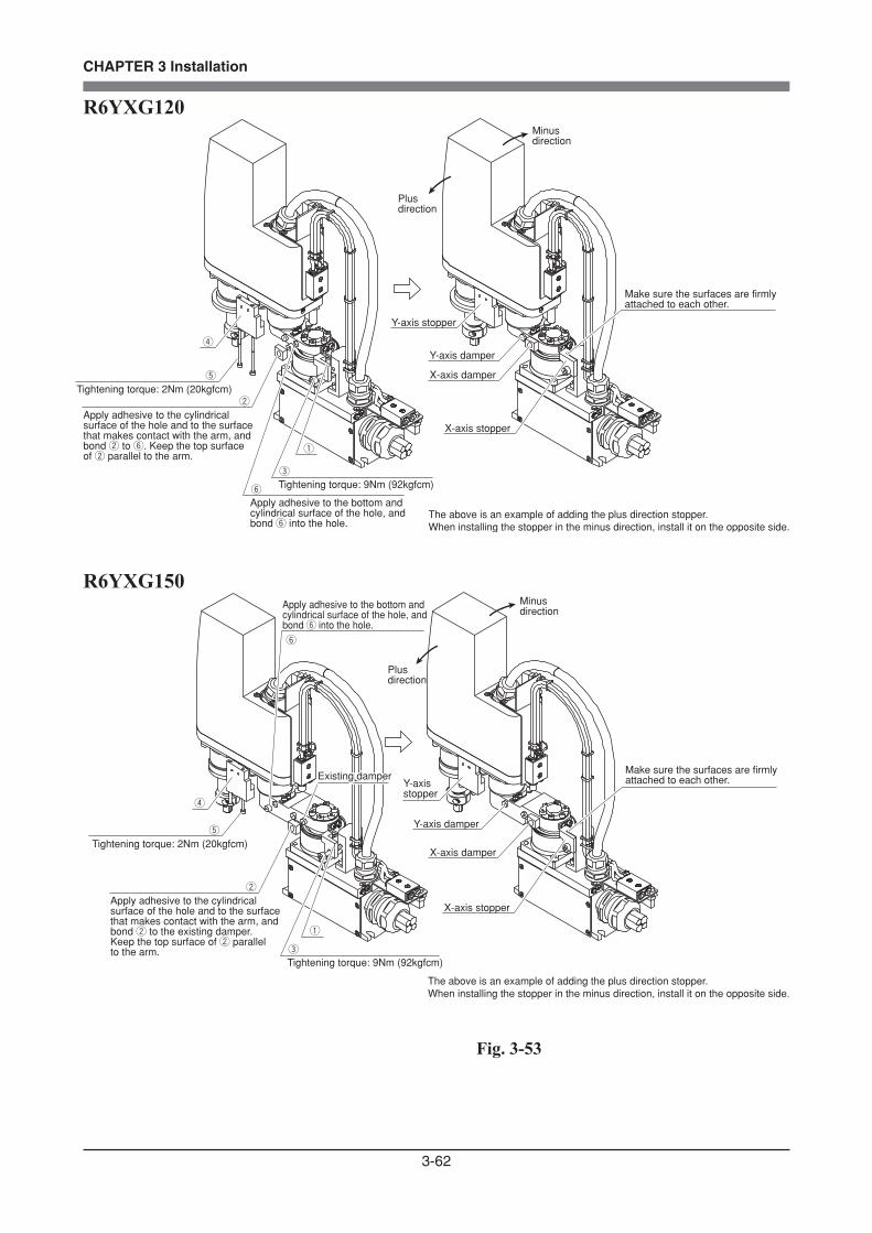
3-62
CHAPTER 3 Installation
R6YXG120Minus direction
Plus direction
Make sure the surfaces are firmly attached to each other.
Y-axis stopper
Y-axis damper
X-axis damper
X-axis stopper
Tightening torque: 2Nm (20kgfcm)t
Apply adhesive to the cylindrical surface of the hole and to the surface that makes contact with the arm, and bond w to y. Keep the top surface of w parallel to the arm.
w
r
e
Tightening torque: 9Nm (92kgfcm)
q
The above is an example of adding the plus direction stopper.When installing the stopper in the minus direction, install it on the opposite side.
y
Apply adhesive to the bottom and cylindrical surface of the hole, and bond y into the hole.
R6YXG150Minus direction
Plus direction
Make sure the surfaces are firmly attached to each other.Y-axis
stopper
Y-axis damper
X-axis damper
X-axis stopper
Tightening torque: 2Nm (20kgfcm)t
Apply adhesive to the cylindrical surface of the hole and to the surface that makes contact with the arm, and bond w to the existing damper. Keep the top surface of w parallel to the arm.
w
r
e
Tightening torque: 9Nm (92kgfcm)
q
The above is an example of adding the plus direction stopper.When installing the stopper in the minus direction, install it on the opposite side.
y
Apply adhesive to the bottom and cylindrical surface of the hole, and bond y into the hole.
Existing damperExisting damper
Fig. 3-53

3-63
CHAPTER 3 Installation
R6YXG180Minus direction
Plus direction
Make sure the surfaces are firmly attached to each other.Y-axis
stopper
Y-axis damper
X-axis damper
X-axis stopper
Tightening torque: 2Nm (20kgfcm)t
r
e
Tightening torque: 9Nm (92kgfcm)
q
The above is an example of adding the plus direction stopper.When installing the stopper in the minus direction, install it on the opposite side.
y
Apply adhesive to the bottom and cylindrical surface of the hole, and bond y into the hole.
w
Apply adhesive to the cylindrical surface of the hole and to the surface that makes contact with the arm, and bond w to y. Keep the top surface of w parallel to the arm.
Fig. 3-53
The M3 tapped holes in the Y-axis stopper block can also be used to attach a tool.
8
32 10
2-M3x0.5 tapped holes for attaching toolDo not screw the screws in deeper than 6mm from the stopper block surface.The weight of the tool attached here should be added to the tip mass.
Fig. 3-54

3-64
CHAPTER 3 Installation
11-2-3 Installing the additional mechanical stopper in the Z-axis minus direction
Install the additional mechanical stopper in the Z-axis minus direction by following the instructions shown in Fig. 3-55.
1) Prepare the hex wrench set and torque wrench.
2) Turn off the robot controller.
3) Place a sign indicating the robot is being adjusted, to keep others from touching the controller switch.
4) Enter the safeguard enclosure.
5) Remove the Y-axis arm cover by referring to section 7 in Chapter 4, and move up the urethane damper.
6) Install the additional stopper 3 to the spline shaft by tightening the supplied bolts to the specified torque. Alternately tighten the bolts a little at a time. Depending on the relation to the Z-axis machine reference adjustment, L2 in Table 3-7 will be a position of approximately 12, 24, 36 or 48mm.
7) Go out of the safeguard enclosure.
8) Check that no one is inside the safeguard enclosure, and then turn on the controller.
9) Place a sign indicating the robot is being adjusted, to keep others from operating the controller or operation panel.
10) Perform the Z-axis absolute reset. To perform the Z-axis absolute reset, see "3-3 Absolute reset procedures" in
Chapter 4. Make a note of the Z-axis machine reference value.
(1) Press the MODE key.(2) Press the F3 key to enter MANUAL mode.(3) Press the F13 key (LOWER+F3) to select "ABS Reset".(4) After the Z-axis absolute reset is complete, press the F10 (UPPER+F5) key
to display the adjustment machine reference value (%).
CAUTIONUSE THE FOLLOWING PROCEDURE TO DISPLAY THE ADJUSTMENT MACHINE REFERENCE VALUE. WHEN ADJUSTING THE MACHINE REFERENCE VALUE, ALWAYS CHECK THE ADJUSTMENT MACHINE REFERENCE VALUE WITH THIS PROCEDURE.
3-65
CHAPTER 3 Installation
When the machine reference is within the allowable range (between 17 and 33%), proceed to step 16). If the machine reference is outside the allowable range, adjust it as described in step 11) onward.
11) Turn off the controller and enter the safeguard enclosure.
12) Put a mark at the added stopper position 3 and loosen the bolt for the added stopper.
To adjust the machine reference value, move the added stopper as follows: Machine reference value < 17% : Move the added stopper in the plus direction. Machine reference value > 33% : Move the added stopper in the minus direction. As an approximate guide, a 12mm movement equals 100%.
13) Repeat the same procedure from step 6) until the machine reference is within the allowable range.
14) When the machine reference is set within the allowable range, go out of the safeguard enclosure.
15) Check that no one is inside the safeguard enclosure and then turn on the controller.
16) Set the soft limits as shown in Table 3-7. The soft limit in the minus direction is already set by default to the value
shown in Table 3-7.
17) Stay outside the safeguard enclosure and check that the soft limits work to stop the Z-axis unit at a point before the stopper position. Depending on the accuracy and position of the stopper parts, the Z-axis unit may not stop until it reaches the stopper. In this case, set the soft limits larger than the values shown in Table 3-7.
18) Check that the movement range is limited by the stoppers as desired.
19) Turn off the controller and enter the safeguard enclosure.
20) Reattach the Y-axis arm cover.

3-66
CHAPTER 3 Installation
R6YXG120, R6YXG150, R6YXG180
Bolt supplied with eTightening torque: 4.5Nm (46kgfcm)
Minus direction stopper
q wTightening torque: 2Nm (20kgfcm)
Plus direction stopper
Move up the urethane damper.
Minus direction
Plus direction
e
Fig. 3-55
3-67
CHAPTER 3 Installation
11-2-4 Installing the additional mechanical stopper in the Z-axis plus direction
Install the additional mechanical stopper in the Z-axis plus direction by following the instructions shown in Fig. 3-55.
1) Prepare the hex wrench set and torque wrench.
2) Turn off the robot controller.
3) Place a sign indicating the robot is being adjusted, to keep others from touching the controller switch.
4) Enter the safeguard enclosure.
5) Remove the Y-axis arm cover by referring to section 7 in Chapter 4, and move up the urethane damper.
6) Install the additional stopper 1 to the ball screw by tightening the bolts 2 to the specified torque.
Alternately tighten the bolts a little at a time. There is no restriction on the stopper position in the plus direction.
7) Go out of the safeguard enclosure.
8) Check that no one is inside the safeguard enclosure, and then turn on the controller.
9) Place a sign indicating the robot is being adjusted, to keep others from operating the controller or operation panel.
10) Set the soft limit in the plus direction as shown in Table 3-7.
11) Stay outside the safeguard enclosure and check that the soft limits work to stop the Z-axis unit at a point before the stopper position.
Depending on the accuracy and position of the stopper parts, the Z-axis unit may not stop until it reaches the stopper. In this case, set the soft limits smaller than the values shown in Table 3-7.
12) Check that the movement range is limited by the stoppers as desired.
13) Turn off the controller and enter the safeguard enclosure.
14) Reattach the Y-axis arm cover.

3-68
CHAPTER 3 Installation
11-2-5 Overrun amounts during impacts with X, Y and Z-axis additional mechanical stoppers
A urethane damper is installed to absorb the shock when an impact occurswith the mechanical stopper, so a certain amount of overrun occurs when therobot strikes the mechanical stopper. Use caution and take overrun into account since the end effector may interfere with the robot body and peripheral equipment or the robot body may interfere with the peripheral equipment.Maximum overrun amounts are listed below (for normal operation, maximumpayload, maximum speed).
4mm
Lower end
2mm
Upper end
Z-axis
14°
Y-axis
26°
X-axis
Note: Here,° (deg.) is the overrun angle at the X-axis and Y-axis joints.
(1) If the X-axis, Y-axis or Z-axis mechanical stopper is deformed or damaged by impacts, please contact our sales office or dealer. Using the deformed or damaged mechanical stopper is dangerous, so it must be replaced.
(2) When the robot strikes the X-axis or Y-axis mechanical stopper or another object, or when the R-axis collides with an object, speed reduction gears are locked while being meshed if the collision impact is large. If this happens, please contact our sales office or dealer.
(3) After the robot strikes the Z-axis mechanical stopper, the stopper position may shift, and so check the stopper position. If shifted, move the stopper to the correct position and refasten it securely by following the assembly procedure.

CHAPTER 4
Adjustment
1 Overview ..............................................................................................................4-1
2 Safety Precautions ................................................................................................4-1
3 Adjusting the Origin .............................................................................................4-23-1 Absolute reset method .........................................................................................................4-3
3-1-1 R6YXC120 and R6YXC150 robots ..................................................................................... 4-33-1-1-1 Sensor method (R-axis) ....................................................................................................... 4-33-1-1-2 Stroke end method (X-axis, Y-axis) .................................................................................... 4-43-1-1-3 Stroke end method (Z-axis) ................................................................................................. 4-6
3-1-2 R6YXC180, R6YXC220, R6YXG120, R6YXG150, R6YXG180
and R6YXG220 robots ......................................................................................................... 4-73-1-2-1 Sensor method (R-axis) ....................................................................................................... 4-73-1-2-2 Sensor method (X-axis, Y-axis) ........................................................................................... 4-83-1-2-3 Stroke end method (Z-axis) ................................................................................................. 4-9
3-2 Machine reference .............................................................................................................4-103-3 Absolute reset procedures .................................................................................................. 4-11
3-3-1 Sensor method (R-axis) .......................................................................................................4-11
3-3-2 Stroke end method (X and Y axes of R6YXC120, R6YXC150) ....................................... 4-13
3-3-3 Stroke end method (Z-axis) ................................................................................................ 4-15
3-3-4 Sensor method (X and Y axes of R6YXG120, R6YXG150,R6YXG180, R6YXG220,
R6YXC180, R6YXC220)) ................................................................................................. 4-16
3-4 Adjusting the machine reference .......................................................................................4-183-4-1 R6YXC120, R6YXC150 robots ......................................................................................... 4-19
3-4-1-1 Adjusting the R-axis machine reference (R6YXC120, R6YXC150) ................................ 4-193-4-1-2 Adjusting the X-axis machine reference ........................................................................... 4-213-4-1-3 Adjusting the Y-axis machine reference ............................................................................ 4-233-4-1-4 Adjusting the Z-axis machine reference ............................................................................ 4-25
3-4-2 R6YXG120, R6YXG150, R6YXG180, R6YXG220, R6YXC180,R6YXC220 robots .... 4-283-4-2-1 Adjusting the R-axis machine reference ........................................................................... 4-283-4-2-2 Adjusting the X-axis machine reference ........................................................................... 4-303-4-2-3 Adjusting the Y-axis machine reference ............................................................................ 4-323-4-2-4 Adjusting the Z-axis machine reference (R6YXC180, R6YXC220 robots) ..................... 4-343-4-2-5 Adjusting the Z-axis machine reference (R6YXG120, R6YXG150 robots) .................... 4-37
4 Setting the Soft Limits ........................................................................................4-40

5 Setting the Standard Coordinates .......................................................................4-43
6 Affixing Stickers for Movement Directions and Axis Names ............................4-44
7 Removing the Robot Covers ...............................................................................4-46
4-1
CHAPTER 4 Adjustment
1 OverviewOMRON robots have been completely adjusted at the factory or by the sales representative before shipment, including the origin position adjustment. If the operating conditions are changed and the robot must be adjusted, then follow the procedures described in this chapter.
2 Safety Precautions(1) Read and understand the contents of this chapter completely before
attempting to adjust the robot.
(2) Place a conspicuous sign indicating the robot is being adjusted, to prevent others from touching the controller switch, programming box or operation panel.
(3) If a safeguard enclosure has not yet been provided right after installation of the robot, rope off or chain off the movement area around the manipulator in place of a safeguard enclosure, and observe the following points.1- Use stable posts which will not fall over easily.2- The rope or chain should be easily visible by everyone around the robot.3- Place a conspicuous sign prohibiting the operator or other personnel from
entering the movement area of the manipulator.
(4) To check operation after adjustment, refer to "6. Trial Operation" in Chapter 1.
4-2
CHAPTER 4 Adjustment
3 Adjusting the OriginAll models of the XG series and XC series robots use an absolute type position detector.The origin position (zero pulse point) can be determined by absolute reset. Once absolute reset is performed, you do not have to repeat absolute reset when turning the power on next time.However, absolute reset is required if any of the following cases occur. The robot is shipped from the factory in condition "c" (below), so please perform absolute reset after installing the robot. For more details on absolute reset, refer to "Absolute Reset" in Chapter 4 of the "OMRON Robot Controller User's Manual".
a. Absolute-related error occurred on the axis.b. Power drop was detected in the absolute battery for the driver installed
inside the robot controller.c. Cable connecting the robot unit to the controller was disconnected. (This is the status when shipped from the factory.)d. Robot generation was changed.e. Parameters were initialized.f. Axis parameters "Origin shift", "Origin method", "Origin direction" or
"Motor direction" were changed. g. Motor was replaced. (Motor wiring connector was removed.)h. Data in the ALL data file (extension: ALL) or parameter file (extension:
PRM) was written into the controller by way of the RS-232C.
The following sections explain how to perform absolute reset.
The XG series and XC series absolute methods include the sensor method and stroke end method.The R6YXC120 and R6YXC150 robots uses the stroke end method for the X-axis, Y-axis and Z-axis, and the sensor method for the R-axis.The R6YXC180, R6YXC220, R6YXG120, R6YXG150, R6YXG180 and R6YXG220 robots use the stroke end method for the Z-axis, and the sensor method for the X-axis, Y-axis and R-axis.
CAUTIONIF ANY OF THE ABOVE CASES OCCUR AFTER INSTALLING THE ROBOT, ABSOLUTE RESET MUST BE PERFORMED AGAIN. THE ROBOT MUST BE MOVED TO THE ORIGIN POSITION TO PERFORM ABSOLUTE RESET. SELECT A ROBOT POSITION WHERE THE ORIGIN POSITION WILL NOT INTERFERE WITH PERIPHERAL DEVICES AFTER SETUP IS COMPLETED.
CAUTIONAFTER PERFORMING ABSOLUTE RESET, MOVE THE ROBOT TO A KNOWN POINT TO CHECK WHETHER THE ORIGIN POSITION IS CORRECTLY SET. WHEN DOING THIS CHECK, MOVE THE ROBOT AT THE SLOWEST POSSIBLE SPEED.
4-3
CHAPTER 4 Adjustment
3-1 Absolute reset method
3-1-1 R6YXC120 and R6YXC150 robots
3-1-1-1 Sensor method (R-axis)
In the sensor method, the target axis is automatically operated for the absolute reset, and the absolute reset is performed at the position where the proximity sensor provided on the target axis detects the detection area (dog).The absolute reset in the sensor method can be executed with the programming box (PB), RS-232C communication, and dedicated input.
WARNINGSERIOUS INJURY MIGHT OCCUR FROM PHYSICAL CONTACT WITH THE ROBOT DURING OPERATION. NEVER ENTER WITHIN THE ROBOT MOVEMENT RANGE DURING ABSOLUTE RESET.
CAUTIONTHE ORIGIN CANNOT BE DETECTED IN ANY AXIS WHICH IS NOT POSITIONED ON THE PLUS SIDE FROM THE ORIGIN (SEE FIG. 4-1.) BEFORE STARTING THE RETURN-TO-ORIGIN OPERATION. (FACTORY SETTING AT SHIPMENT.) IN THIS CASE, PRESS THE STOP KEY TO INTERRUPT THE RETURN-TO-ORIGIN OPERATION, MOVE THE TARGET AXIS TO THE PLUS SIDE OF THE ORIGIN, AND REPERFORM THE ORIGIN RETURN OPERATION. IF THE RETURN-TO-ORIGIN OPERATION IS NOT STOPPED, THE ROBOT WILL CONTINUE MOVING AND COULD COLLIDE WITH THE PERIPHERAL DEVICES. THE R-AXIS DOES NOT HAVE A MECHANICAL STOPPER, SO THE WIRING AND PIPING INSTALLED ON THE END EFFECTOR COULD BECOME ENTANGLED.
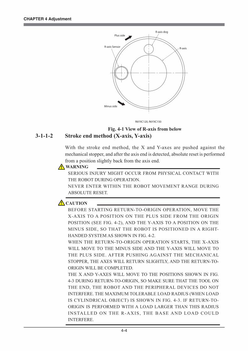
4-4
CHAPTER 4 Adjustment
Plus side
Minus side
R-axis dog
R-axis Sensor R-axis
R6YXC120, R6YXC150
Fig. 4-1 View of R-axis from below3-1-1-2 Stroke end method (X-axis, Y-axis)
With the stroke end method, the X and Y-axes are pushed against the mechanical stopper, and after the axis end is detected, absolute reset is performed from a position slightly back from the axis end. WARNING
SERIOUS INJURY MIGHT OCCUR FROM PHYSICAL CONTACT WITH THE ROBOT DURING OPERATION. NEVER ENTER WITHIN THE ROBOT MOVEMENT RANGE DURING ABSOLUTE RESET.
CAUTIONBEFORE STARTING RETURN-TO-ORIGIN OPERATION, MOVE THE X-AXIS TO A POSITION ON THE PLUS SIDE FROM THE ORIGIN POSITION (SEE FIG. 4-2), AND THE Y-AXIS TO A POSITION ON THE MINUS SIDE, SO THAT THE ROBOT IS POSITIONED IN A RIGHT-HANDED SYSTEM AS SHOWN IN FIG. 4-2. WHEN THE RETURN-TO-ORIGIN OPERATION STARTS, THE X-AXIS WILL MOVE TO THE MINUS SIDE AND THE Y-AXIS WILL MOVE TO THE PLUS SIDE. AFTER PUSHING AGAINST THE MECHANICAL STOPPER, THE AXES WILL RETURN SLIGHTLY, AND THE RETURN-TO-ORIGIN WILL BE COMPLETED. THE X AND Y-AXES WILL MOVE TO THE POSITIONS SHOWN IN FIG. 4-3 DURING RETURN-TO-ORIGIN, SO MAKE SURE THAT THE TOOL ON THE END, THE ROBOT AND THE PERIPHERAL DEVICES DO NOT INTERFERE. THE MAXIMUM TOLERABLE LOAD RADIUS (WHEN LOAD IS CYLINDRICAL OBJECT) IS SHOWN IN FIG. 4-3. IF RETURN-TO-ORIGIN IS PERFORMED WITH A LOAD LARGER THAN THIS RADIUS INSTALLED ON THE R-AXIS, THE BASE AND LOAD COULD INTERFERE.
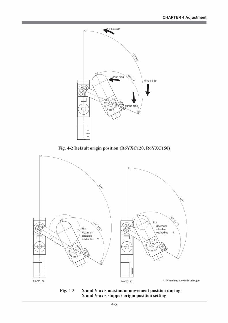
4-5
CHAPTER 4 Adjustment
139°±4°
113°±4°
Plus side
Minus side
Minus side
Plus side
Fig. 4-2 Default origin position (R6YXC120, R6YXC150)
147˚ (143˚)121˚
147˚ (143˚)121˚
R38
R13
Maximum tolerable load radius
Maximum tolerable load radius
R6YXC150 R6YXC120 *1 When load is cylindrical object
*1
*1
Fig. 4-3 X and Y-axis maximum movement position during X and Y-axis stopper origin position setting

4-6
CHAPTER 4 Adjustment
3-1-1-3 Stroke end method (Z-axis)
With this method, the Z-axis is pushed against the mechanical stopper, and after the axis end is detected, absolute reset is performed from a position slightly back from the axis end.
WARNINGSERIOUS INJURY MIGHT OCCUR FROM PHYSICAL CONTACT WITH THE ROBOT DURING OPERATION. NEVER ENTER WITHIN THE ROBOT MOVEMENT RANGE DURING ABSOLUTE RESET.
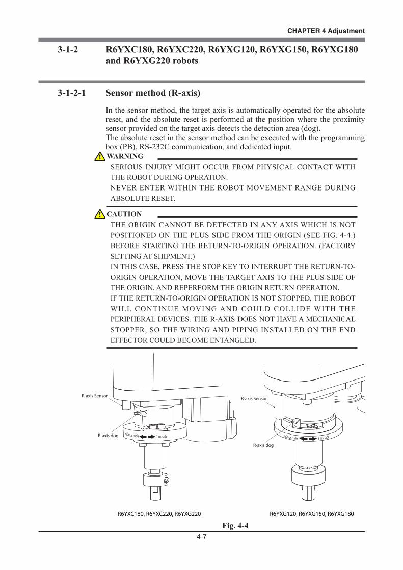
4-7
CHAPTER 4 Adjustment
3-1-2 R6YXC180, R6YXC220, R6YXG120, R6YXG150, R6YXG180 and R6YXG220 robots
3-1-2-1 Sensor method (R-axis)
In the sensor method, the target axis is automatically operated for the absolute reset, and the absolute reset is performed at the position where the proximity sensor provided on the target axis detects the detection area (dog).The absolute reset in the sensor method can be executed with the programming box (PB), RS-232C communication, and dedicated input.
P lus s ideM inus s ide
P lus s ideM inus s ide
R-axis Sensor
R-axis dog
R-axis Sensor
R-axis dog
R6YXC180, R6YXC220, R6YXG220 R6YXG120, R6YXG150, R6YXG180
Fig. 4-4
WARNINGSERIOUS INJURY MIGHT OCCUR FROM PHYSICAL CONTACT WITH THE ROBOT DURING OPERATION. NEVER ENTER WITHIN THE ROBOT MOVEMENT RANGE DURING ABSOLUTE RESET.
CAUTIONTHE ORIGIN CANNOT BE DETECTED IN ANY AXIS WHICH IS NOT POSITIONED ON THE PLUS SIDE FROM THE ORIGIN (SEE FIG. 4-4.) BEFORE STARTING THE RETURN-TO-ORIGIN OPERATION. (FACTORY SETTING AT SHIPMENT.) IN THIS CASE, PRESS THE STOP KEY TO INTERRUPT THE RETURN-TO-ORIGIN OPERATION, MOVE THE TARGET AXIS TO THE PLUS SIDE OF THE ORIGIN, AND REPERFORM THE ORIGIN RETURN OPERATION. IF THE RETURN-TO-ORIGIN OPERATION IS NOT STOPPED, THE ROBOT WILL CONTINUE MOVING AND COULD COLLIDE WITH THE PERIPHERAL DEVICES. THE R-AXIS DOES NOT HAVE A MECHANICAL STOPPER, SO THE WIRING AND PIPING INSTALLED ON THE END EFFECTOR COULD BECOME ENTANGLED.

4-8
CHAPTER 4 Adjustment
3-1-2-2 Sensor method (X-axis, Y-axis)
WARNINGSERIOUS INJURY MIGHT OCCUR FROM PHYSICAL CONTACT WITH THE ROBOT DURING OPERATION. NEVER ENTER WITHIN THE ROBOT MOVEMENT RANGE DURING ABSOLUTE RESET.
CAUTIONTHE ORIGIN CANNOT BE DETECTED IN ANY AXIS WHICH IS NOT POSITIONED ON THE PLUS SIDE FROM THE ORIGIN (SEE FIG. 4-5.) BEFORE STARTING THE RETURN-TO-ORIGIN OPERATION. (FACTORY SETTING AT SHIPMENT.) IN THIS CASE, PRESS THE STOP KEY TO INTERRUPT THE RETURN-TO-ORIGIN OPERATION, MOVE THE TARGET AXIS TO THE PLUS SIDE OF THE ORIGIN, AND REPERFORM THE ORIGIN RETURN OPERATION. IF THE RETURN-TO-ORIGIN OPERATION IS NOT STOPPED, THE ROBOT WILL CONTINUE MOVING AND COULD COLLIDE WITH THE PERIPHERAL DEVICES. THE X AND Y-AXES WILL MOVE TO THE POSITIONS SHOWN IN FIG. 4-5 DURING RETURN-TO-ORIGIN, SO MAKE SURE THAT THE TOOL ON THE END, THE ROBOT AND THE PERIPHERAL DEVICES DO NOT INTERFERE. THE MAXIMUM TOLERABLE LOAD RADIUS (WHEN LOAD IS CYLINDRICAL OBJECT) IS SHOWN IN FIG. 4-5. IF RETURN-TO-ORIGIN IS PERFORMED WITH A LOAD LARGER THAN THIS RADIUS INSTALLED ON THE R-AXIS, THE BASE AND LOAD COULD INTERFERE. SINCE THE X-AXIS ARM FIRST RETURNS TO THE ORIGIN, THE TOOL ON THE END MIGHT INTERFERE WITH THE ROBOT BASE (PEDESTAL) IF THE Y-AXIS ARM IS NEAR ITS ORIGIN.

4-9
CHAPTER 4 Adjustment
X-axis origin is at 0°±5° with respect to front of robot base
X-axis origin is at 0°±5° with respect to front of robot base
X and Y axis origins are at 0°±5° with respect to front of robot base
133°±5°
133°±5°
*1 When load is cylindrical object
R6YXC180 R6YXG220, R6YXC220
R19
R17
Plus side Minus side Plus side Minus sidePlus side Minus side
Plus side Minus side
Minus side
Plus side
Minus side
Plus side
Maximum tolerable load radius *1
Maximum tolerable load radius *1
R6YXG120, R6YXG150, R6YXG180
Fig. 4-5 Default origin position
3-1-2-3 Stroke end method (Z-axis)
With this method, the Z-axis is pushed against the mechanical stopper, and after the axis end is detected, absolute reset is performed from a position slightly back from the axis end.
WARNINGSERIOUS INJURY MIGHT OCCUR FROM PHYSICAL CONTACT WITH THE ROBOT DURING OPERATION. NEVER ENTER WITHIN THE ROBOT MOVEMENT RANGE DURING ABSOLUTE RESET.
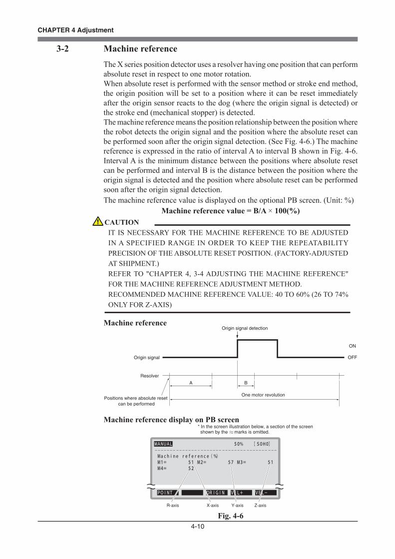
4-10
CHAPTER 4 Adjustment
3-2 Machine referenceThe X series position detector uses a resolver having one position that can perform absolute reset in respect to one motor rotation.When absolute reset is performed with the sensor method or stroke end method, the origin position will be set to a position where it can be reset immediately after the origin sensor reacts to the dog (where the origin signal is detected) or the stroke end (mechanical stopper) is detected. The machine reference means the position relationship between the position where the robot detects the origin signal and the position where the absolute reset can be performed soon after the origin signal detection. (See Fig. 4-6.) The machine reference is expressed in the ratio of interval A to interval B shown in Fig. 4-6. Interval A is the minimum distance between the positions where absolute reset can be performed and interval B is the distance between the position where the origin signal is detected and the position where absolute reset can be performed soon after the origin signal detection.The machine reference value is displayed on the optional PB screen. (Unit: %)
Machine reference value = B/A × 100(%)
Machine referenceOrigin signal detection
Origin signal
Resolver
Positions where absolute reset can be performed
One motor revolution
BA
ON
OFF
Machine reference display on PB screen* In the screen illustration below, a section of the screen shown by the marks is omitted.
MANUAL 50% [ S0H0]
Machine reference ( %) M1= 51 M2= 57 M3= 51 M4= 52
POINT ORIGIN VEL+ VEL-
R-axis X-axis Y-axis Z-axis
Fig. 4-6
CAUTIONIT IS NECESSARY FOR THE MACHINE REFERENCE TO BE ADJUSTED IN A SPECIFIED RANGE IN ORDER TO KEEP THE REPEATABILITY PRECISION OF THE ABSOLUTE RESET POSITION. (FACTORY-ADJUSTED AT SHIPMENT.) REFER TO "CHAPTER 4, 3-4 ADJUSTING THE MACHINE REFERENCE" FOR THE MACHINE REFERENCE ADJUSTMENT METHOD. RECOMMENDED MACHINE REFERENCE VALUE: 40 TO 60% (26 TO 74% ONLY FOR Z-AXIS)

4-11
CHAPTER 4 Adjustment
3-3 Absolute reset procedures
3-3-1 Sensor method (R-axis)
The operation procedure using the PB is described next. (Press the ESC key on the PB if you want to return to the preceding step.)See the "OMRON Robot Controller User's Manual" for information on operating the robot controller.
1) Check that no one is inside the safeguard enclosure, and then turn on the controller.
2) Place a sign indicating the robot is being adjusted, to keep others from touching the controller switch or operation panel.
3) Set the controller to MANUAL mode, if not in MANUAL mode.
4) Press the F13 (LOWER+F3) key to select "RST. ABS".
5) Select the R-axis for absolute reset. (R-axis: M4) To perform absolute reset on all axes, select "ALL" with the F11 (LOWER+F1)
key.
6) Confirm that the R-axis, to perform absolute reset, is at a position on the plus side of the origin (See Fig. 4-1, Fig. 4-4 ).
If it is not at the plus side, then press the jog key to move the target axis to the plus side.
When performing absolute reset for the other axes at the same time, confirm that the other axes are also at an appropriate position. (Refer to procedures for absolute reset of other axes)
WARNINGSERIOUS INJURY MIGHT OCCUR FROM PHYSICAL CONTACT WITH THE ROBOT DURING OPERATION. NEVER ENTER WITHIN THE ROBOT MOVEMENT RANGE DURING ABSOLUTE RESET.
CAUTIONTHE Z-AXIS OF THE STROKE END METHOD FIRST RISES DURING THE ABSOLUTE RESET OF ALL AXES (DEFAULT SETTING). BE CAREFUL THAT YOUR FINGERS DO NOT GET PINCHED OR CRUSHED BY ANY SUDDEN MOVEMENT.
4-12
CHAPTER 4 Adjustment
7) Since the message "Reset ABS encoder OK?" is displayed, check that there are not any obstacles in the robot movement range, and press the F4 key (YES).
8) After the absolute reset is completed, check that the R-axis machine reference value displayed on the PB is between 40 and 60 (recommended range).
If the machine reference value is outside the recommended range, then the next absolute reset may not be properly performed.
In this case, refer to "3-4 Adjusting the machine reference", and make the necessary adjustments.

4-13
CHAPTER 4 Adjustment
3-3-2 Stroke end method (X and Y axes of R6YXC120, R6YXC150)
The operation procedure using the PB is described next. (Press the ESC key onthe PB if you want to return to the preceding step.)See the "OMRON Robot Controller User's Manual" for information on operating the robot controller.
1) Check that no one is inside the safeguard enclosure, and then turn on the controller.
2) Place a sign indicating the robot is being adjusted, to keep others from touching the controller switch or operation panel.
3) Set the controller to MANUAL mode, if not in MANUAL mode.
4) Press the F13 (LOWER+F3) key to select "RST. ABS".
5) Select the X-axis or Y-axis for absolute reset. (X-axis: M1, Y-axis: M2) To perform absolute reset on all axes, select "ALL" with the F11 (LOWER+F1)
key.
6) Confirm that the X-axis is at a position on the plus side of the origin (See Fig. 4-2), and that the Y-axis is at the minus side. Make sure that the robot is positioned in a right-handed system as shown in Fig. 4-2. If the axes are not at these positions, press the jog keys, etc., and move the target axes. When performing absolute reset for the other axes at the same time, confirm that the other axes are also at an appropriate position. (Refer to procedures for absolute reset of other axes)
7) Since the message "Reset ABS encoder OK?" is displayed, check that there are not any obstacles in the robot movement range, and press the F4 key (YES).
WARNINGSERIOUS INJURY MIGHT OCCUR FROM PHYSICAL CONTACT WITH THE ROBOT DURING OPERATION. NEVER ENTER WITHIN THE ROBOT MOVEMENT RANGE DURING ABSOLUTE RESET.
CAUTIONTHE Z-AXIS OF THE STROKE END METHOD FIRST RISES DURING THE ABSOLUTE RESET OF ALL AXES (DEFAULT SETTING). BE CAREFUL THAT YOUR FINGERS DO NOT GET PINCHED OR CRUSHED BY ANY SUDDEN MOVEMENT.
4-14
CHAPTER 4 Adjustment
8) After the absolute reset is completed, check that the X-axis and Y-axis machine reference value displayed on the PB is within the absolute reset tolerance range (40 to 60).
If the machine reference value is outside the absolute reset tolerance range, then the next absolute reset may not be properly performed.
In this case, refer to "Chapter 4, 3-4 Adjusting the machine reference" and make the necessary adjustments.
4-15
CHAPTER 4 Adjustment
3-3-3 Stroke end method (Z-axis)
The operation procedure using the PB is described next. (Press the ESC key onthe PB if you want to return to the preceding step.)See the "OMRON Robot Controller User's Manual" for information on operating the robot controller.
1) Check that no one is inside the safeguard enclosure, and then turn on the controller.
2) Place a sign indicating the robot is being adjusted, to keep others from touching the controller switch or operation panel.
3) Set the controller to MANUAL mode, if not in MANUAL mode.
4) Press the F13 (LOWER+F3) key to select "RST. ABS".
5) Select M3 (Z-axis). (Z-axis: M3) To perform absolute reset on all axes, select "ALL" with the F11 (LOWER+F1)
key.
6) Since the message "Reset ABS encoder OK?" is displayed, check that there are not any obstacles in the robot movement range, and press the F4 key (YES).
7) After the absolute reset is completed, check that the machine reference value displayed on the PB is within the absolute reset tolerance range.
Absolute reset tolerance range :26 to 74% (R6YXG220) : 17 to 33% (R6YXG120, R6YXG150, R6YXG180) If the machine reference value is outside the absolute reset tolerance range,
then the next absolute reset may not be properly performed. In this case, refer to "Chapter 4, 3-4 Adjusting the machine reference" and
make the necessary adjustments.
WARNINGSERIOUS INJURY MIGHT OCCUR FROM PHYSICAL CONTACT WITH THE ROBOT DURING OPERATION. NEVER ENTER WITHIN THE ROBOT MOVEMENT RANGE DURING ABSOLUTE RESET.
4-16
CHAPTER 4 Adjustment
3-3-4 Sensor method (X and Y axes of R6YXG120, R6YXG150, R6YXG180, R6YXG220, R6YXC180, R6YXC220)
The operation procedure using the PB is described next. (Press the ESC key onthe PB if you want to return to the preceding step.)See the "OMRON Robot Controller User's Manual" for information on operating the robot controller.
1) Check that no one is inside the safeguard enclosure, and then turn on the controller.
2) Place a sign indicating the robot is being adjusted, to keep others from touching the controller switch or operation panel.
3) Set the controller to MANUAL mode, if not in MANUAL mode.
4) Press the F13 (LOWER+F3) key to select "RST. ABS".
5) Select the X-axis or Y-axis for absolute reset. (X-axis: M1, Y-axis: M2) To perform absolute reset on all axes, select "ALL" with the F11 (LOWER+F1)
key.
6) Move the X and Y axes to a position on the plus side of their origins (See Fig. 4-5) so that the robot is positioned in a left-handed system as shown in Fig. 4-5. If the axes are not at these positions, press the jog keys, etc. and move the target axes. When performing absolute reset for the other axes at the same time, check that the other axes are also at an appropriate position. (Refer to procedures for absolute reset of other axes.)
7) Since the message "Reset ABS encoder OK?" is displayed, check that there are not any obstacles in the robot movement range, and press the F4 key (YES).
WARNINGSERIOUS INJURY MIGHT OCCUR FROM PHYSICAL CONTACT WITH THE ROBOT DURING OPERATION. NEVER ENTER WITHIN THE ROBOT MOVEMENT RANGE DURING ABSOLUTE RESET.
CAUTIONTHE Z-AXIS OF THE STROKE END METHOD FIRST RISES DURING THE ABSOLUTE RESET OF ALL AXES (DEFAULT SETTING). BE CAREFUL THAT YOUR FINGERS DO NOT GET PINCHED OR CRUSHED BY ANY SUDDEN MOVEMENT.

4-17
CHAPTER 4 Adjustment
8) After the absolute reset is completed, check that the X-axis and Y-axis machine reference value displayed on the PB is within the absolute reset tolerance range (40 to 60).
If the machine reference value is outside the absolute reset tolerance range, then the next absolute reset may not be properly performed.
In this case, refer to "Chapter 4, 3-4 Adjusting the machine reference" and make the necessary adjustments.
4-18
CHAPTER 4 Adjustment
3-4 Adjusting the machine reference
CAUTIONIF ANY MACHINE REFERENCE IS ADJUSTED, THE ORIGIN POSITION MAY CHANGE. BEFORE THE ADJUSTMENT, MARK OFF THE REFERENCE MARK AT THE CURRENT ORIGIN POSITION ON THE MAIN BODY OF THE ROBOT. AFTER THE MACHINE REFERENCE IS ADJUSTED, BE SURE TO CHECK THAT THE ORIGIN POSITION HAS NOT DEVIATED. IF THE ORIGIN POSITION CHANGES AFTER THE MACHINE REFERENCE HAS BEEN ADJUSTED, THEN THE STANDARD COORDINATE AND POINT DATA MUST BE RESET.
CAUTIONWHEN THE ARM MOVES AT HIGH SPEED AND STRIKES AGAINST A MECHANICAL STOPPER VIOLENTLY, THE MACHINE REFERENCE VALUE MAY CHANGE. IF THIS HAS HAPPENED, CHECK THE MACHINE REFERENCE VALUE. ALSO CHECK THE MECHANICAL STOPPER FOR ANY DAMAGE AND THE ORIGIN POSITION FOR SHIFT. IF THE MACHINE REFERENCE VALUE IS OUTSIDE THE RECOMMENDED RANGE, ADJUST THE MACHINE REFERENCE. IN THIS CASE, RETEACHING MAY BE REQUIRED IF THE ORIGIN POSITION HAS SHIFTED..

4-19
CHAPTER 4 Adjustment
3-4-1 R6YXC120, R6YXC150 robots
3-4-1-1 Adjusting the R-axis machine reference (R6YXC120, R6YXC150)
The adjustment method for the R-axis machine reference is as follows.
1) Prepare the necessary tools.• Hex wrench set
2) Check that no one is inside the safeguard enclosure, and then turn on the controller.
3) Perform the absolute reset from outside the safeguard enclosure. Refer to "3-3 Absolute reset procedures" for information about the absolute
reset method.
4) If any machine reference value displayed on the PB is not in the range between 40 and 60 (recommended range) after the absolute reset has been completed, then proceed with the following adjustment procedure.
5) Place a sign indicating that the robot is being adjusted in order to keep others from operating the controller or operation panel.
6) Turn off the controller and enter the safeguard enclosure.
7) Mark off the reference mark at the current origin position on the R-axis joint area of the robot.
At this time, be careful to prevent the origin position from deviating since the R-axis is touched.
8) Using a hex wrench, loosen the set screws (4 pieces) securing the dog ring to the R-axis joint. (See Fig. 4-8.)
9) Move the dog ring in the following manner. When machine reference < 40%: Move dog ring in A direction When machine reference > 60%: Move dog ring in B direction As an approximate guide, a movement of 2.9mm equals 100%.
CAUTIONTHE SET SCREWS ONLY NEED TO BE LOOSENED, AND DO NOT NEED TO BE COMPLETELY REMOVED.

4-20
CHAPTER 4 Adjustment
10) Tighten the set screws to secure the dog ring. Rotate the R-axis by hand to check that the dog and sensor do not come in contact with each other. (See Fig. 4-8.)
11) Go out of the safeguard enclosure, and check that no one is inside the safeguard enclosure. Then turn on the controller.
12) Perform the absolute reset from outside the safeguard enclosure.
13) After the absolute reset is completed, read the machine reference value displayed on the PB.
14) If the machine reference value is in the range between 40 and 60 (recommended range), then the machine reference has been completely adjusted.
If it is outside the recommended range, then repeat the procedure that starts in 5) to readjust it.
R-axis
Dog ringSet screw (4 pieces)B A
Fig. 4-8 Adjustment of R-axis machine reference
4-21
CHAPTER 4 Adjustment
3-4-1-2 Adjusting the X-axis machine reference
The adjustment method for the X-axis machine reference is as follows.
1) Prepare the necessary tools.• Hex wrench set
2) Check that no one is inside the safeguard enclosure, and then turn on the controller.
3) Perform the absolute reset from outside the safeguard enclosure. Refer to "3-3 Absolute reset procedures" for information about the absolute
reset method.
4) If any machine reference value displayed on the PB is not in the range between 40 and 60 (recommended range) after the absolute reset has been completed, then proceed with the following adjustment procedure.
5) Place a sign indicating that the robot is being adjusted in order to keep others from operating the controller or operation panel.
6) Turn off the controller and enter the safeguard enclosure.
7) Mark off the reference mark at the current origin position on the X-axis joint area of the robot.
At this time, be careful to prevent the origin position from deviating since the X-axis arm is touched.
8) Using a hexagon wrench, loosen the two bolts fixing the X-axis movable mechanical stopper. (See Fig. 4-9.)
9) Move the movable mechanical stopper in the following manner. When machine reference < 40% : Move mechanical stopper in A direction When machine reference > 60% : Move mechanical stopper in B direction As an approximate guide, a movement of 2.2mm equals 100%.
10) Tighten the bolt and fix the movable mechanical stopper. The tightening torque is 4.4kgfcm (0.43Nm).
CAUTIONTHE BOLT ONLY NEEDS TO BE LOOSENED, AND DOES NOT NEED TO BE COMPLETELY REMOVED.

4-22
CHAPTER 4 Adjustment
11) Go out of the safeguard enclosure, and check that no one is inside the safeguard enclosure. Then turn on the controller.
12) Perform the absolute reset from outside the safeguard enclosure.
13) After completing absolute reset, check the machine reference value.
14) If the machine reference value is in the range between 40 and 60 (recommended range), then the machine reference has been completely adjusted.
If it is outside the recommended range, then repeat the procedure that starts in 5) to readjust it.
X-axis moveable mechanical stopper (on back side of arm looking from above)
X-axis fixed mechanical stopper
Bolt
X-axis arm
B
A
Fig. 4-9 Adjustment of X-axis machine reference
4-23
CHAPTER 4 Adjustment
3-4-1-3 Adjusting the Y-axis machine reference
The adjustment method for the Y-axis machine reference is as follows.
1) Prepare the necessary tools.• Hex wrench set
2) Check that no one is inside the safeguard enclosure, and then turn on the controller.
3) Perform the absolute reset from outside the safeguard enclosure. Refer to "3-3 Absolute reset procedures" for information about the absolute
reset method.
4) If any machine reference value displayed on the PB is not in the range between 40 and 60 (recommended range) after the absolute reset has been completed, then proceed with the following adjustment procedure.
5) Place a sign indicating that the robot is being adjusted in order to keep others from operating the controller or operation panel.
6) Turn off the controller and enter the safeguard enclosure.
7) Mark off the reference mark at the current origin position on the Y-axis joint area of the robot.
At this time, be careful to prevent the origin position from deviating since the Y-axis arm is touched.
8) Using a hexagon wrench, loosen the two bolts fixing the Y-axis movable mechanical stopper. (See Fig. 4-10.)
9) Move the movable mechanical stopper in the following manner. When machine reference < 40% : Move mechanical stopper in A direction When machine reference > 60% : Move mechanical stopper in B direction As an approximate guide, a movement of 3.5mm equals 100%.
10) Tighten the bolt and fix the movable mechanical stopper. The tightening torque is 4.4kgfcm (0.43Nm).
CAUTIONTHE BOLT ONLY NEEDS TO BE LOOSENED, AND DOES NOT NEED TO BE COMPLETELY REMOVED.
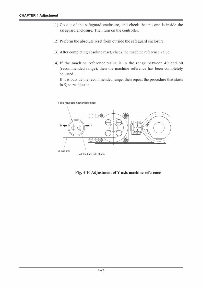
4-24
CHAPTER 4 Adjustment
11) Go out of the safeguard enclosure, and check that no one is inside the safeguard enclosure. Then turn on the controller.
12) Perform the absolute reset from outside the safeguard enclosure.
13) After completing absolute reset, check the machine reference value.
14) If the machine reference value is in the range between 40 and 60 (recommended range), then the machine reference has been completely adjusted.
If it is outside the recommended range, then repeat the procedure that starts in 5) to readjust it.
B A
Bolt (On back side of arm)
Y-axis moveable mechanical stopper
X-axis arm
Fig. 4-10 Adjustment of Y-axis machine reference

4-25
CHAPTER 4 Adjustment
3-4-1-4 Adjusting the Z-axis machine reference
The stroke end method is employed on the R6YXC120 and R6YXC150 robots for the absolute reset of the Z-axis.The origin position of the Z-axis is fixed at the upper end of the Z-axis stroke, and it cannot be changed.The machine reference is factory-adjusted at shipment, and readjustment is not necessary for normal use.The readjustment in the following procedure is required, however, if the machine reference exceeds the tolerance range (26 to 74) of the absolute reset for any reason.
1) Check that no one is inside the safeguard enclosure, and then turn on the controller.
2) Place a sign indicating the robot is being adjusted, to keep others from operating the controller or operation panel.
3) Perform the Z-axis absolute reset. To perform the Z-axis absolute reset, see "3-3-3 Stroke end method (Z-axis)"
in Chapter 4.
4) Turn off the controller.
5) Enter the safeguard enclosure.
6) Remove the Y-axis upper cover. To remove the covers, see "7 Removing the Robot Covers" in Chapter 4. Place the upper cover on the robot base (pedestal) side with the machine
harness still connected.
7) Confirm that the Z-axis rising end mechanical stopper is at the position shown in Fig. 4-11 (a).
If not at that position, loosen the bolt and fix the stopper at the position shown in the drawing. The tightening torque is 4.4kgfcm (0.43Nm).
Carry out steps 1) to 3) after fixing the mechanical stopper again. After completing absolute reset, check to see if the machine reference value
is within the tolerance range for absolute reset. When within the tolerance range, turn off the controller power switch and reinstall the Y-axis upper cover to complete the work.
CAUTIONTHE ORIGIN POSITION MAY CHANGE WHEN THE MACHINE REFERENCE AMOUNT IS ADJUSTED. THE POINT DATA MUST BE RESET AFTER ADJUSTING THE MACHINE REFERENCE.
4-26
CHAPTER 4 Adjustment
8) If the machine reference value is not within the tolerance range (26 to 74%) perform the following steps.
9) With the robot controller's power ON, apply emergency stop on the controller and release the Z-axis brakes. Refer to the "OMRON Robot Controller User's Manual" for details on emergency stop, releasing emergency stop, releasing the Z-axis brakes and turning the brakes ON.
10) Loosen the set screw (two screws on upper side) fixing the ball screw in Fig. 4-11 (b), and change the phase of the ball screw in respect to the sleeve as shown below.
When machine reference 5%: Turn ball screw 180° clockwise looking from above When 5% < machine reference < 26%: Turn ball screw 90° clockwise looking from above When 74% < machine reference < 90%: Turn ball screw 90° counterclockwise looking from above When 90% machine reference: Turn ball screw 180° counterclockwise looking from above
11) Tighten the set screw and fix the ball screw. The tightening torque is 17kgfcm (1.7Nm).
12) Exit the safeguard enclosure.
13) Confirm that there no workers in the safeguard enclosure, and then release the controller emergency stop state.
14) After completing absolute reset for the Z-axis, check to see if the machine reference value is within the tolerance range for absolute reset.
15) Turn the controller power OFF.
16) Install the Y-axis arm upper cover.
CAUTIONTHE Z-AXIS WILL SLIDE DOWN WHEN THE Z-AXIS BRAKE IS RELEASED, CAUSING A HAZARDOUS SITUATION. • PRESS THE EMERGENCY STOP BUTTON AND PROP UP THE Z-AXIS WITH A SUPPORT STAND BEFORE RELEASING THE BRAKE.

4-27
CHAPTER 4 Adjustment6
Z-axis upper end mechanical stopper position
(b)
(a)
(c)
Bolt
Upper end mechanical stopper
Linear shaft
Ball screw
Ball screw
Sleeve
Set screw
Set screw
Ball screw
Section
Fig. 4-11
4-28
CHAPTER 4 Adjustment
3-4-2 R6YXG120, R6YXG150, R6YXG180, R6YXG220, R6YXC180, R6YXC220 robots
3-4-2-1 Adjusting the R-axis machine reference
The adjustment method for the R-axis machine reference is as follows.
1) Prepare the necessary tools.• Phillips-head screwdriver
2) Check that no one is inside the safeguard enclosure, and then turn on the controller.
3) Perform the absolute reset from outside the safeguard enclosure. Refer to "3-3 Absolute reset procedures" for information about the absolute
reset method.
4) If any machine reference value displayed on the PB is not in the range between 40 and 60 (recommended range) after the absolute reset has been completed, then proceed with the following adjustment procedure.
5) Place a sign indicating that the robot is being adjusted in order to keep others from operating the controller or operation panel.
6) Turn off the controller and enter the safeguard enclosure.
7) Mark off the reference mark at the current origin position on the R-axis joint area of the robot.
At this time, be careful to prevent the origin position from deviating since the R-axis is touched.
8) • Using a hex wrench, loosen the bolts (2 pieces) securing the dog on the R-axis joint. (R6YXG220, R6YXC180 and R6YXC220)
• Using a wrench (5.5mm width across flats, 2mm thickness), loosen the bolt (1 piece) securing the dog on the R-axis joint. (R6YXG120, R6YXG150 and R6YXG180)
(See Fig. 4-12.)
CAUTIONTHE BOLT ONLY NEEDS TO BE LOOSENED, AND DOES NOT NEED TO BE COMPLETELY REMOVED.
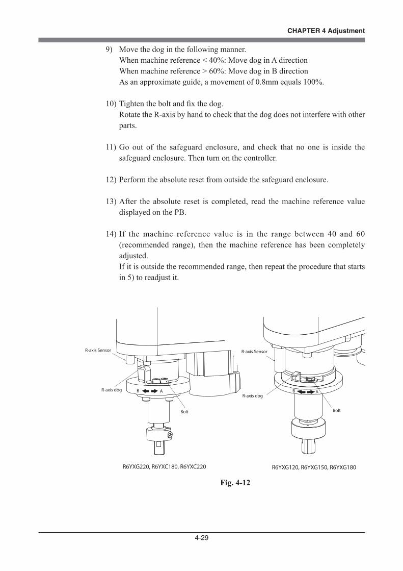
4-29
CHAPTER 4 Adjustment
9) Move the dog in the following manner. When machine reference < 40%: Move dog in A direction When machine reference > 60%: Move dog in B direction As an approximate guide, a movement of 0.8mm equals 100%.
10) Tighten the bolt and fix the dog. Rotate the R-axis by hand to check that the dog does not interfere with other
parts.
11) Go out of the safeguard enclosure, and check that no one is inside the safeguard enclosure. Then turn on the controller.
12) Perform the absolute reset from outside the safeguard enclosure.
13) After the absolute reset is completed, read the machine reference value displayed on the PB.
14) If the machine reference value is in the range between 40 and 60 (recommended range), then the machine reference has been completely adjusted.
If it is outside the recommended range, then repeat the procedure that starts in 5) to readjust it.
B A
R-axis Sensor
R-axis dog
Bolt
R-axis Sensor
R-axis dog
Bolt
B A
R6YXG220, R6YXC180, R6YXC220 R6YXG120, R6YXG150, R6YXG180
Fig. 4-12
4-30
CHAPTER 4 Adjustment
3-4-2-2 Adjusting the X-axis machine reference
The adjustment method for the X-axis machine reference is as follows.
1) Prepare the necessary tools.• Hex wrench set
2) Check that no one is inside the safeguard enclosure, and then turn on the controller.
3) Perform the absolute reset from outside the safeguard enclosure. Refer to "3-3 Absolute reset procedures" for information about the absolute
reset method.
4) If any machine reference value displayed on the PB is not in the range between 40 and 60 (recommended range) after the absolute reset has been completed, then proceed with the following adjustment procedure.
5) Place a sign indicating that the robot is being adjusted in order to keep others from operating the controller or operation panel.
6) Turn off the controller and enter the safeguard enclosure.
7) Mark off the reference mark at the current origin position on the X-axis joint area of the robot.
At this time, be careful to prevent the origin position from deviating since the X-axis arm is touched.
8) Using a hex wrench, loosen the bolts (2 pieces) securing the X-axis dog. (See Fig. 4-13.)
9) Move the movable mechanical stopper in the following manner. When machine reference < 40% : Move mechanical stopper in A direction When machine reference > 60% : Move mechanical stopper in B direction As an approximate guide, a movement of 1mm equals 100% (for R6YXG220,
R6YXC180 and R6YXC220), and a movement of 0.5mm equals 100% (for R6YXG120, R6YXG150 and R6YXG180).
10) Tighten the bolt and fix the movable mechanical stopper. The tightening torque is 20kgfcm (2.0Nm).
CAUTIONTHE BOLT ONLY NEEDS TO BE LOOSENED, AND DOES NOT NEED TO BE COMPLETELY REMOVED.

4-31
CHAPTER 4 Adjustment
11) Go out of the safeguard enclosure, and check that no one is inside the safeguard enclosure. Then turn on the controller.
12) Perform the absolute reset from outside the safeguard enclosure.
13) After completing absolute reset, check the machine reference value.
14) If the machine reference value is in the range between 40 and 60 (recommended range), then the machine reference has been completely adjusted.
If it is outside the recommended range, then repeat the procedure that starts in 5) to readjust it.
X-axis Sensor
X-axis Sensor
X-axis dog
Bolt
X-axis dog
Bolt
A
B
AAB
R6YXG220, R6YXC180, R6YXC220 R6YXG120, R6YXG150, R6YXG180
Fig. 4-13 Adjustment of X-axis machine reference
4-32
CHAPTER 4 Adjustment
3-4-2-3 Adjusting the Y-axis machine reference
The adjustment method for the Y-axis machine reference is as follows.
1) Prepare the necessary tools.• Hex wrench set
2) Check that no one is inside the safeguard enclosure, and then turn on the controller.
3) Perform the absolute reset from outside the safeguard enclosure. Refer to "3-3 Absolute reset procedures" for information about the absolute
reset method.
4) If any machine reference value displayed on the PB is not in the range between 40 and 60 (recommended range) after the absolute reset has been completed, then proceed with the following adjustment procedure.
5) Place a sign indicating that the robot is being adjusted in order to keep others from operating the controller or operation panel.
6) Turn off the controller and enter the safeguard enclosure.
7) Mark off the reference mark at the current origin position on the Y-axis joint area of the robot.
At this time, be careful to prevent the origin position from deviating since the Y-axis arm is touched.
8) Using a hex wrench, loosen the bolts (2 pieces) securing the Y-axis dog. (See Fig. 4-14.)
9) Move the movable mechanical stopper in the following manner. When machine reference < 40% : Move mechanical stopper in A direction When machine reference > 60% : Move mechanical stopper in B direction As an approximate guide, a movement of 1.1mm equals 100%.
10) Tighten the bolt and fix the movable mechanical stopper. The tightening torque is 20kgfcm (2.0Nm).
CAUTIONTHE BOLT ONLY NEEDS TO BE LOOSENED, AND DOES NOT NEED TO BE COMPLETELY REMOVED.

4-33
CHAPTER 4 Adjustment
11) Go out of the safeguard enclosure, and check that no one is inside the safeguard enclosure. Then turn on the controller.
12) Perform the absolute reset from outside the safeguard enclosure.
13) After completing absolute reset, check the machine reference value.
14) If the machine reference value is in the range between 40 and 60 (recommended range), then the machine reference has been completely adjusted.
If it is outside the recommended range, then repeat the procedure that starts in 5) to readjust it.
Y-axis dog
Bolt
A
B
R6YXG220, R6YXC180, R6YXC220 R6YXG120, R6YXG150, R6YXG180
A
BBY-axis Sensor
Y-axis dog
Bolt
Y-axis Sensor
Fig. 4-14 Adjustment of Y-axis machine reference

4-34
CHAPTER 4 Adjustment
3-4-2-4 Adjusting the Z-axis machine reference (R6YXC180, R6YXC220 robots)
The stroke end method is employed on the R6YXC180 and R6YXC220 robots for the absolute reset of the Z-axis.The origin position of the Z-axis is fixed at the upper end of the Z-axis stroke, and it cannot be changed.The machine reference is factory-adjusted at shipment, and readjustment is not necessary for normal use.The readjustment in the following procedure is required, however, if the machine reference exceeds the tolerance range (26 to 74) of the absolute reset for any reason.
1) Check that the Z-axis upper-end mechanical stopper is at the position shown in Fig. 4-15.
If not, loosen the bolt and adjust the mechanical stopper to the specified position. Retighten the bolt to a torque of 20kgfcm (2.0Nm).
2) Check that no one is inside the safeguard enclosure, and then turn on the
controller.
3) Place a sign indicating the robot is being adjusted, to keep others from operating the controller or operation panel.
4) Perform the Z-axis absolute reset. To perform the Z-axis absolute reset, see "3-3-3 Stroke end method (Z-axis)"
in Chapter 4.
(1) Press the MODE key.(2) Press the F3 key to enter MANUAL mode.(3) Press the F13 key (LOWER+F3) to select "ABS Reset".(4) After the Z-axis absolute reset is complete, press the F10 (UPPER+F5) key
to display the adjustment machine reference value (%).
5) After completing absolute reset, check to see if the machine reference value is within the tolerance range for absolute reset. When within the tolerance range (26 to 74%), the distance between the upper end urethane damper and the lower end of the spline nut is approximately 5mm.
6) If the machine reference value is not within the tolerance range, perform the following steps.
CAUTIONTHE ORIGIN POSITION MAY CHANGE WHEN THE MACHINE REFERENCE AMOUNT IS ADJUSTED. THE POINT DATA MUST BE RESET AFTER ADJUSTING THE MACHINE REFERENCE.
4-35
CHAPTER 4 Adjustment
7) Turn off the controller.
8) Enter the safeguard enclosure.
9) Remove the Y-axis upper cover. To remove the covers, see "7 Removing the Robot Covers" in Chapter 4. Place the upper cover on the robot base (pedestal) side with the machine
harness still connected.
10) Lift up the lower end urethane damper and loosen the bolts (6 pieces) securing the ball screw shown in Fig. 4-15. Then rotate the ball screw with respect to the Z-axis motor so that the distance between the upper end urethane damper and the lower end of the spline is 5mm. When the lower end position of the ball screw is determined, push the ball screw in so that it makes contact with the bottom of the Z-axis motor installation hole.
11) Tighten the bolts to secure the ball screw. The tightening torque should be 20kgfcm (2.0Nm).
Tighten the bolts a little at a time in a diagonal pattern. Otherwise, the ball screw might be off-center. After tightening the bolts securely, lower the lower end urethane damper.
12) Exit the safeguard enclosure.
13) Check that no one is inside the safeguard enclosure, and then turn on the controller.
14) Perform absolute reset on the Z-axis, and when completed, check that the adjustment machine reference value is within the absolute reset tolerance range.
15) Turn the controller power OFF.
16) Install the Y-axis arm upper cover.
WARNINGTHE Z-AXIS WILL SLIDE DOWN DURING THE FOLLOWING WORK, CAUSING A HAZARDOUS SITUATION. PROP UP THE Z-AXIS WITH A SUPPORT STAND BEFORE BEGINNING THE WORK.

4-36
CHAPTER 4 Adjustment
5
15
Spline nut
Upper end urethane damper
Z-axis upper-end mechanical stopper
Bolt
Z-axis motor
Bolt
Ball screw
Lower end urethane damper
Fig. 4-15

4-37
CHAPTER 4 Adjustment
3-4-2-5 Adjusting the Z-axis machine reference (R6YXG120, R6YXG150 robots)
The stroke end method is employed on the R6YXG120 and R6YXG150 robots for the absolute reset of the Z-axis. The origin position of the Z-axis is fixed at the upper end of the Z-axis stroke, and it cannot be changed. The machine reference is factory-adjusted at shipment, and readjustment is not necessary for normal use. The readjustment in the following procedure is required, however, if the machine reference exceeds the tolerance range (17 to 33) of the absolute reset for any reason.
1) Check that no one is inside the safeguard enclosure, and then turn on the controller.
2) Place a sign indicating the robot is being adjusted, to keep others from operating the controller or operation panel.
3) Perform the Z-axis absolute reset. To perform the Z-axis absolute reset, see "3-3 Absolute reset procedures" in
Chapter 4. Make a note of the Z-axis machine reference value.
(1) Press the MODE key.(2) Press the F3 key to enter MANUAL mode.(3) Press the F13 key (LOWER+F3) to select "ABS Reset".(4) After the Z-axis absolute reset is complete, press the F10 (UPPER+F5) key
to display the adjustment machine reference value (%).
4) Turn off the controller. The Z-axis motor brake is now working at the origin position.
5) Enter the safeguard enclosure.
6) Remove the cover. To remove the covers, see "7 Removing the Robot Covers" in Chapter 4.
Place the upper cover on the robot base (pedestal) side with the machine harness still connected.
CAUTIONTHE ORIGIN POSITION MAY CHANGE DUE TO MACHINE REFERENCE ADJUSTMENT. IF IT OCCURS, YOU MUST SET POINT DATA AGAIN.
CAUTIONUSE THE FOLLOWING PROCEDURE TO DISPLAY THE ADJUSTMENT MACHINE REFERENCE VALUE. WHEN ADJUSTING THE MACHINE REFERENCE VALUE, ALWAYS CHECK THE ADJUSTMENT MACHINE REFERENCE VALUE WITH THIS PROCEDURE.

4-38
CHAPTER 4 Adjustment
7) Prop the spline or end effector with a support stand to prevent the Z-axis from dropping.
8) Lift up the Z-axis lower end damper. If this is difficult, insert a screwdriver between the damper and the holder, and pry up the damper. (See Fig. 4-16.)
9) Put a mark to indicate the current flange position with respect to the motor shaft. Fit the spanner (wrench) to the flat surfaces of the flange and loosen the bolts. This allows the ball screw to rotate freely independent of the Z-axis motor.
10) Rotate the flange with respect to the motor shaft. (See Fig. 4-17.) Rotating the flange 45 degrees changes the machine reference value by 13%.
The machine reference value decreases by rotating the flange clockwise as viewed from top, while it increases by rotating the flange counterclockwise. Determine the flange position based on the Z-axis machine reference value you made a note of, so that the machine reference value is within 17 to 33%.
11) Tighten the bolts a little at a time in a diagonal pattern. The tightening torque should be 0.43Nm (4.4kgfcm).
12) Go outside the safeguard enclosure.
13) Check that no one is inside the safeguard enclosure, and then turn on the controller.
14) Perform the Z-axis absolute reset. To perform the Z-axis absolute reset, see "3-3 Absolute reset procedures" in
Chapter 4. After absolute reset is complete, check that the adjustment machine
reference value is within the tolerance range (17 and 33). If the adjustment machine reference value is outside the tolerance range (17 to 33), then repeat the procedure from 4) to readjust it.
15) When the machine reference value is within the tolerance range, lower the Z-axis lower end damper until it makes tight contact with the holder and then reattach the cover.
WARNINGIF THE BALL SCREW COMES OFF THE Z-AXIS MOTOR, THE Z-AXIS DROPS CAUSING A HAZARDOUS SITUATION. ALWAYS PROP UP THE Z-AXIS WITH A SUPPORT STAND OR THE LIKE.

4-39
CHAPTER 4 Adjustment
Ball screw
Z-axis lower end damper
Flat surface
Z-axis motor shaft(located under the flange)
Flange
Mark
M2×8 Bolt
Fig. 4-16
CounterclockwiseCounterclockwise
ClockwiseClockwise
Fig. 4-17

4-40
CHAPTER 4 Adjustment
4 Setting the Soft LimitsIn the R6YXG120, R6YXG150, R6YXG180, R6YXG220, R6YXC120, R6YXC150, R6YXC180 and R6YXC220 robots, the working envelope during manual and automatic operation can be limited by setting the plus soft limit [pulses] and minus soft limit [pulses] on each axis.The origin point ( 0 [pulses] ) is used as the reference to set the soft limits. The working envelope can be limited by specifying the number of pulses from the 0 pulse position. Refer to the "OMRON Robot Controller User's Manual" for further details. Also refer to "1-2 External view and dimensions" in Chapter 7 for the working envelope area.When performing actual checks of the soft limit settings, operate the robot manually from outside the safeguard enclosure.
(1) Setting the X-axis and Y-axis soft limitsSet the soft limit on the inner side of the movement range limited by the mechanical stopper or on the inner side of the position that interferes with the peripheral devices (note that this must within the maximum working envelope). Set the soft limit with the following procedures.
1) Check that no one is inside the safeguard enclosure, and then turn on the controller.
2) Press the emergency stop button on the PB to set emergency stop. Refer to the "OMRON Robot Controller User's Manual" for further details
on emergency stop and canceling emergency stop.
3) Place a sign indicating the robot is being adjusted, to keep others from operating the controller or operation panel.
4) Enter the safeguard enclosure while holding the PB.
5) Move the X-axis and Y-axis arms by hand to the mechanical stopper positions or to the point where interference with the peripheral equipment occurs, and note the X-axis and Y-axis plus (+) and minus (-) direction pulses displayed on the PB.
6) Check that no one is inside the safeguard enclosure, then cancel emergency stop from outside the safeguard enclosure.
4-41
CHAPTER 4 Adjustment
7) Set the soft limits to within the figure for the X-axis and Y-axis encoder pulses that you noted above in step 5). This software limit setting must be made from outside the safeguard enclosure.
Refer to the "OMRON Robot Controller User's Manual" for further details on soft limit settings.
CAUTIONTHE ORIGIN POSITION ADJUSTED BEFORE SHIPMENT MAY VARY AS SHOWN IN "CHAPTER 7, 1-2 EXTERNAL VIEW AND DIMENSIONS". WHEN INTRODUCING THE ROBOT, BE SURE TO SET THE SOFT LIMITS WITH THE NUMBER OF PULSES FROM THE ORIGIN POSITION (0 PULSE POSITION).

4-42
CHAPTER 4 Adjustment
(2) Setting the Z-axis soft limitsMake this setting from outside the safeguard enclosure.The Z-axis has mechanical stoppers fixed at the upper and lower ends of the Z-axis movement range. When the actual working range of the robot is smaller than the maximum working envelope or the manipulator interferes with the peripheral equipment, reduce the Z-axis plus (+) soft limit [pulses] to narrow the working envelope.
(3) Setting the R-axis soft limitTo make this setting, set emergency stop just as for the X-axis and Y-axis, or be sure to do this from outside the safeguard enclosure. The R-axis has no mechanical stoppers. When the actual working range of the R-axis is small or it interferes with the peripheral equipment, reduce the R axis plus (+) soft limit [pulse] and minus (-) soft limit [pulses] to narrow the working envelope.
(4) Relation between the X, Y and R-axis movement angle, the Z-axis movement distance and the number of pulses
The resolver pulse for X, Y- and R-axes movement angle and the for the Z-axis movement length are shown below. Use these figures as a guide to set the soft limits.
Axis
Z
Number of resolver pulses per 12 mm movement of one lead
4096
Axis
X, Y
R
R6YXC120, R6YXC150
R6YXG120, R6YXG150, R6YXG180, R6YXC120, R6YXC150
Number of resolver pulses per turn (360 degrees)
204800
122880
Axis
Z
Number of resolver pulses per 12 mm movement of one lead
16384
Axis
X, Y
R
R6YXG120, R6YXG150, R6YXG180, R6YXG220, R6YXC180, R6YXC220
R6YXG220, R6YXC180, R6YXC220
Number of resolver pulses per turn (360 degrees)
819200
491520
CAUTIONOVERLOADS MAY OCCUR IF THE SOFT LIMIT IS ALMOST NEAR THE ENCODER PULSE AT THE MECHANICAL STOPPER AND THE OPERATING POINT IS USED AT THE EDGE OF THE MOVEMENT RANGE. SET THE SOFT LIMIT TO THE INNER SIDE OF THE MECHANICAL STOPPER WITH AN AMPLE SAFETY MARGIN.

4-43
CHAPTER 4 Adjustment
5 Setting the Standard Coordinates
Setting the standard coordinates enables the following operations and functions.1. Optimizes acceleration according to arm position during automatic operation.2. Allows moving robot arm tip at right angles.3. Allows using shift coordinates.4. Enables commands such as linear interpolation and arm switching.
The procedure for setting standard coordinates and cautions are shown below.
1) Check that no one is inside the safeguard enclosure, and then turn on the controller.
2) Check that the soft limits are correctly set. If not correctly set, adjust the soft limits while referring to the description of
"4 Setting the Soft Limits" in Chapter 4.
3) Place a sign indicating the robot is being adjusted, to keep others from operating the controller or operation panel.
4) Enter the safeguard enclosure while holding the PB. Stay outside the robot movement range at this time.
5) Make the standard coordinate settings while referring to methods for "Setting the Standard Coordinates" as explained in the "OMRON Robot Controller User's Manual". Never enter within the robot movement range.
6) When the standard coordinate settings are complete, check the following points from outside the safeguard enclosure.1. Check that the robot arm tip can move at right angles in MANUAL
operation (cartesian coordinates).2. Check that the values nearly equal to the X-axis and Y-axis arm lengths
are entered in "Arm length" of the axis parameters. If the above points are not satisfied, the standard coordinate settings are
incorrect, so make the standard coordinate settings again.
CAUTIONIF THE STANDARD COORDINATE SETTINGS ARE INCORRECT, THE ACCELERATION CANNOT BE OPTIMIZED TO MATCH THE ARM POSITION. THIS RESULTS IN TOO SHORT A SERVICE LIFE, DAMAGE TO THE DRIVE UNIT, OR RESIDUAL VIBRATION DURING POSITIONING. IN ADDITION, THE CARTESIAN COORDINATE ACCURACY WILL BE IMPAIRED.
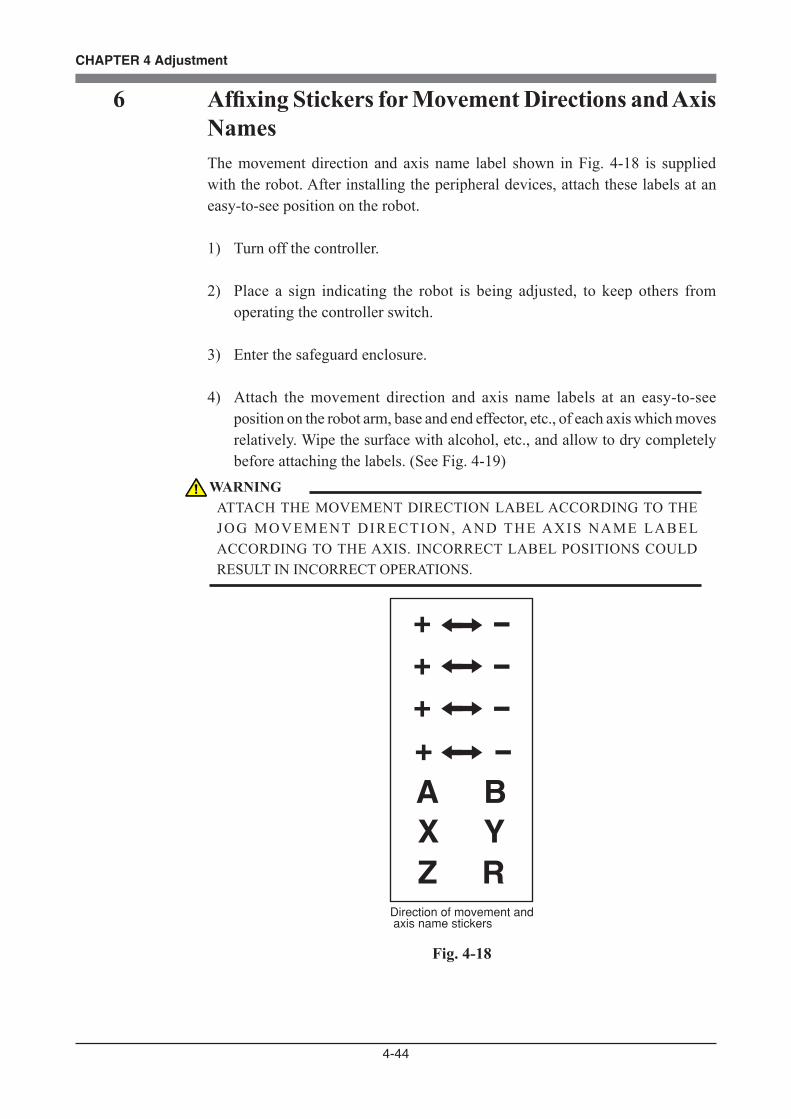
4-44
CHAPTER 4 Adjustment
6 Affixing Stickers for Movement Directions and Axis NamesThe movement direction and axis name label shown in Fig. 4-18 is supplied with the robot. After installing the peripheral devices, attach these labels at an easy-to-see position on the robot.
1) Turn off the controller.
2) Place a sign indicating the robot is being adjusted, to keep others from operating the controller switch.
3) Enter the safeguard enclosure.
4) Attach the movement direction and axis name labels at an easy-to-see position on the robot arm, base and end effector, etc., of each axis which moves relatively. Wipe the surface with alcohol, etc., and allow to dry completely before attaching the labels. (See Fig. 4-19)
A BX YZ R
Direction of movement and axis name stickers
Fig. 4-18
WARNINGATTACH THE MOVEMENT DIRECTION LABEL ACCORDING TO THE JOG MOVEMENT DIRECTION, AND THE AXIS NAME LABEL ACCORDING TO THE AXIS. INCORRECT LABEL POSITIONS COULD RESULT IN INCORRECT OPERATIONS.

4-45
CHAPTER 4 Adjustment
+
-Z
+Y -
-R
- + X
Fig. 4-19 Positions for affixing the stickers

4-46
CHAPTER 4 Adjustment
7 Removing the Robot CoversTo remove the robot cover, follow the procedure below.1) Prepare the necessary tools.
• Phillips-head screwdriver
2) Turn off the controller.
3) Place a sign indicating the robot is being adjusted, to keep others from operating the controller switch.
4) Enter the safeguard enclosure.
5) Remove the covers while referring to Fig. 4-20, Fig. 4-21, Fig. 4-22 and Fig. 4-23.
Base (robot pedestal) side cover
Y-axis arm side cover
Y-axis arm upper cover
3- M2x6 (x2) (this side) M2x4 (x2) (opposite side)
4- M2x4 (x2) (same on opposite side)
1- M2x4 (x4)
R6YXC120, R6YXC150
2- M2x4 (x4) (same on opposite side)
Fig. 4-20
CAUTIONTHE Z-AXIS MIGHT BE LOCKED DEPENDING ON HOW THE Y-AXIS UPPER COVER IS REATTACHED. SO, AFTER REATTACHING THE COVER, RELEASE THE Z-AXIS BRAKE WHILE PROPPING THE Z-AXIS WITH A PROPER SUPPORT OR STAND TO CHECK THAT THE Z-AXIS IS NOT LOCKED.

4-47
CHAPTER 4 Adjustment
Base rear cover
2- M3x6 (x4)
R6YXG220
Base front cover
Y-axis arm upper cover1- M3x6 (x4)
3- M3x6 (x4)
Fig. 4-21
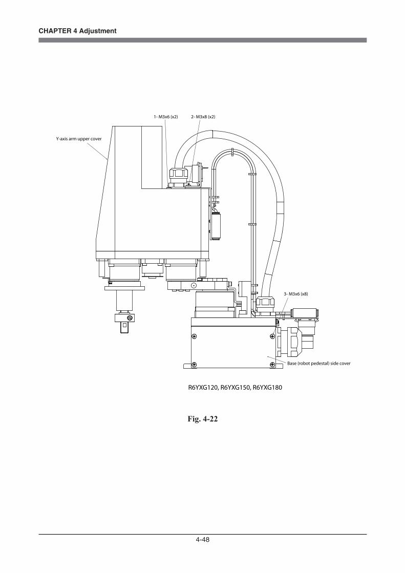
4-48
CHAPTER 4 Adjustment
R6YXG120, R6YXG150, R6YXG180
1- M3x6 (x2) 2- M3x8 (x2)
3- M3x6 (x8)
Y-axis arm upper cover
Base (robot pedestal) side cover
Fig. 4-22

4-49
CHAPTER 4 Adjustment
Base rear cover
3- M3x6 (x6)
2- M3x6 (x26)
R6YXC180, R6YXC220
Base front cover
Cover holderCover holder
Y-axis arm upper cover
1- M3x6 (x4)
4- M3x6 (x6)
Cover holder
Fig. 4-23


CHAPTER 5
Periodic Inspecition
1 Overview ..............................................................................................................5-1
2 Precautions ............................................................................................................5-2
3 Daily Inspection ....................................................................................................5-3
4 Six-Month Inspection ...........................................................................................5-5
5 Replacing the Harmonic Drive Grease .................................................................5-85-1 Replacement period .............................................................................................................5-8


5-1
CHAPTER 5 Periodic Inspection
1 OverviewDaily and periodic inspection of the OMRON robots is essential in order to ensure safe and efficient operation. This chapter describes the periodic inspection items and procedures for the OMRON robots.
Periodic inspection includes: • Daily inspection • 6-month inspection • Replacing the speed reduction gear (harmonic drive) grease
Make sure that you thoroughly understand details of the inspection and follow the procedures and precautions explained in this chapter.

5-2
CHAPTER 5 Periodic Inspection
2 Precautions(1) Periodic inspection must be performed by or in the presence of personnel who
have received the Robot Training given by OMRON or OMRON dealers.
(2) Do not attempt any inspection, adjustment, repair and parts replacement not described in this manual. This work requires specialized technical knowledge and skill, and may also involve work hazards.
(3) When inspection is required inside the safeguard enclosure, always turn off the controller and also the external switch board.
(4) If the inspection or maintenance procedure calls for operation of the robot, stay outside the safeguard enclosure.
(5) Place a sign indicating the robot is being inspected, to keep others from operating the controller switch, programming box or operation panel.
(6) Use only the lubricants specified by OMRON or OMRON dealers.
(7) To check the operation after inspection, refer to "6 Trial operation" in Chapter 1.
For precautions on handling the controller, refer to the "OMRON Robot Controller User's Manual".
WARNING• WHEN YOU NEED TO TOUCH THE TERMINALS OR CONNECTORS ON THE OUTSIDE OF THE CONTROLLER DURING INSPECTION, ALWAYS FIRST TURN OFF THE CONTROLLER POWER SWITCH AND ALSO THE POWER SOURCE IN ORDER TO PREVENT POSSIBLE ELECTRICAL SHOCK. • NEVER TOUCH ANY INTERNAL PARTS OF THE CONTROLLER.
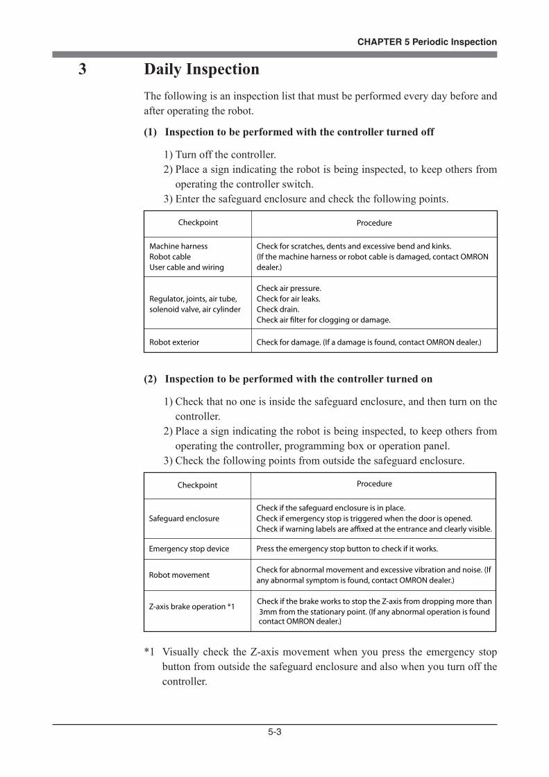
5-3
CHAPTER 5 Periodic Inspection
3 Daily InspectionThe following is an inspection list that must be performed every day before and after operating the robot.
(1) Inspection to be performed with the controller turned off
1) Turn off the controller.2) Place a sign indicating the robot is being inspected, to keep others from
operating the controller switch.3) Enter the safeguard enclosure and check the following points.
Checkpoint Procedure
Machine harnessRobot cableUser cable and wiring
Check for scratches, dents and excessive bend and kinks. (If the machine harness or robot cable is damaged, contact OMRON dealer.)
Regulator, joints, air tube,solenoid valve, air cylinder
Check air pressure.Check for air leaks.Check drain.Check air �lter for clogging or damage.
Robot exterior Check for damage. (If a damage is found, contact OMRON dealer.)
(2) Inspection to be performed with the controller turned on
1) Check that no one is inside the safeguard enclosure, and then turn on the controller.
2) Place a sign indicating the robot is being inspected, to keep others from operating the controller, programming box or operation panel.
3) Check the following points from outside the safeguard enclosure.
Checkpoint Procedure
Safeguard enclosureCheck if the safeguard enclosure is in place.Check if emergency stop is triggered when the door is opened.Check if warning labels are a�xed at the entrance and clearly visible.
Emergency stop device Press the emergency stop button to check if it works.
Robot movementCheck for abnormal movement and excessive vibration and noise. (If any abnormal symptom is found, contact OMRON dealer.)
Z-axis brake operation *1Check if the brake works to stop the Z-axis from dropping more than 3mm from the stationary point. (If any abnormal operation is found
contact OMRON dealer.)
*1 Visually check the Z-axis movement when you press the emergency stop button from outside the safeguard enclosure and also when you turn off the controller.

5-4
CHAPTER 5 Periodic Inspection
(3) Adjustment and parts replacement
1) After inspection, if you notice any adjustment or parts replacement is needed, first turn off the controller and then enter the safeguard enclosure to perform the necessary work. After adjustment or replacement is finished, again review the checkpoints outlined in (1) and (2) above.
2) If repair or parts replacement is required for the robot or controller, please contact your OMRON dealer. This work requires specialized technical knowledge and skill, so do not attempt it by yourself.
5-5
CHAPTER 5 Periodic Inspection
4 Six-Month InspectionTake the following precautions when performing 6-month inspection.
When lubricating the ball screw, spline shaft and linear busing shaft, observe the following precautions.
WARNINGINJURY CAN OCCUR IF HANDS OR FINGERS ARE SQUEEZED BETWEEN THE DRIVE PULLEY AND BELT. ALWAYS TURN OFF THE CONTROLLER AND USE CAUTION WHEN HANDLING THESE PARTS.
WARNINGTHE Z-AXIS WILL SLIDE DOWN WHEN THE Z-AXIS BRAKE IS RELEASED, CAUSING A HAZARDOUS SITUATION. DO NOT RELEASE THE BRAKE WHEN LUBRICATING THE Z-AXIS PARTS.
WARNINGPRECAUTIONS WHEN HANDLING GREASE: •INFLAMMATION MAY OCCUR IF THIS GETS IN THE EYES. BEFORE HANDLING THE GREASE, WEAR YOUR SAFETY GOGGLES TO ENSURE THE GREASE WILL NOT COME IN CONTACT WITH THE EYES. • INFLAMMATION MAY OCCUR IF THE GREASE COMES INTO CONTACT WITH SKIN. BE SURE TO WEAR PROTECTIVE GLOVES TO PREVENT CONTACT WITH SKIN. • DO NOT TAKE ORALLY OR EAT. (EATING WILL CAUSE DIARRHEA AND VOMITING.) • HANDS AND FINGERS MIGHT BE CUT WHEN OPENING THE CONTAINER, SO USE PROTECTIVE GLOVES. • KEEP OUT OF THE REACH OF CHILDREN. • DO NOT HEAT THE GREASE OR PLACE NEAR AN OPEN FLAME SINCE THIS COULD LEAD TO SPARKS AND FIRES. EMERGENCY TREATMENT: • IF THIS GREASE GETS IN THE EYES, WASH LIBERALLY WITH PURE WATER FOR ABOUT 15 MINUTES AND CONSULT A PHYSICIAN FOR TREATMENT. • IF THIS GREASE COMES IN CONTACT WITH THE SKIN, WASH AWAY COMPLETELY WITH SOAP AND WATER. • IF TAKEN INTERNALLY, DO NOT INDUCE VOMITING BUT PROMPTLY CONSULT A PHYSICIAN FOR TREATMENT.
CAUTIONUNLESS GREASE SPECIFIED BY OMRON IS USED, THE SERVICE LIFE OF THE BALL SCREW, BALL SPLINE AND LINEAR BUSHING SHAFT WILL SHORTEN..
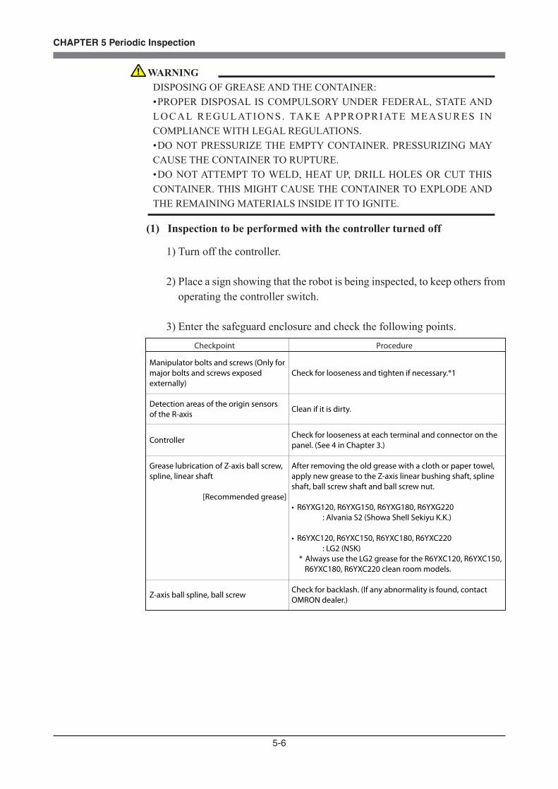
5-6
CHAPTER 5 Periodic Inspection
(1) Inspection to be performed with the controller turned off
1) Turn off the controller.
2) Place a sign showing that the robot is being inspected, to keep others from operating the controller switch.
3) Enter the safeguard enclosure and check the following points.Checkpoint Procedure
Manipulator bolts and screws (Only for major bolts and screws exposed externally)
Detection areas of the origin sensors of the R-axis
Controller
Grease lubrication of Z-axis ball screw, spline, linear shaft
[Recommended grease]
Z-axis ball spline, ball screw
Check for looseness and tighten if necessary.*1
Clean if it is dirty.
Check for looseness at each terminal and connector on the panel. (See 4 in Chapter 3.)
After removing the old grease with a cloth or paper towel, apply new grease to the Z-axis linear bushing shaft, spline shaft, ball screw shaft and ball screw nut.
• R6YXG120, R6YXG150, R6YXG180, R6YXG220 : Alvania S2 (Showa Shell Sekiyu K.K.)
• R6YXC120, R6YXC150, R6YXC180, R6YXC220 : LG2 (NSK)* Always use the LG2 grease for the R6YXC120, R6YXC150,
R6YXC180, R6YXC220 clean room models.
Check for backlash. (If any abnormality is found, contact OMRON dealer.)
WARNINGDISPOSING OF GREASE AND THE CONTAINER: • PROPER DISPOSAL IS COMPULSORY UNDER FEDERAL, STATE AND LOCAL REGULATIONS. TAKE APPROPRIATE MEASURES IN COMPLIANCE WITH LEGAL REGULATIONS. • DO NOT PRESSURIZE THE EMPTY CONTAINER. PRESSURIZING MAY CAUSE THE CONTAINER TO RUPTURE. • DO NOT ATTEMPT TO WELD, HEAT UP, DRILL HOLES OR CUT THIS CONTAINER. THIS MIGHT CAUSE THE CONTAINER TO EXPLODE AND THE REMAINING MATERIALS INSIDE IT TO IGNITE.

5-7
CHAPTER 5 Periodic Inspection
*1 Bolt tightening torque
Bolt size Tightening torque (kgfcm) Tightening torque (Nm)
M3 button head bolt 14 1.4
M3 set screw 7 0.69
M3 bolt installation hole 20 2.0
M4 set screw 20 2.0
M2 bolt installation hole 4.4 0.43
M2.5 bolt installation hole 12 1.2
M4 bolt installation hole 46 4.5
M5 bolt installation hole 92 9.0
M6 bolt installation hole 156 15.3
M8 bolt installation hole 380 37
M10 bolt installation hole 720 71
M12 bolt installation hole
M14 bolt installation hole
1310 128
2090 205
(2) Inspection to be performed with the controller turned on
After turning on the controller, check the following points.
Checkpoint Procedure
• Cooling fan at rear of controller
• Check if the fan rotates normally.• Check if objects blocking the fan are located and remove if any are found.• Check for abnormal noise from the rotating fan. If abnormal noise is heard, visually check and remove the cause. If no cause is found, contact OMRON dealer.• Check for dust on the fan cover. Remove and clean if necessary.
(3) Adjustment and parts replacement
1) After inspection, if you notice any adjustment or parts replacement is needed, first turn off the controller and then enter the safeguard enclosure to perform the necessary work. After adjustment or replacement is finished, again review the checkpoints outlined in (1) and (2) above.
2) If repair or parts replacement is required for the robot or controller, please contact your OMRON dealer. This work requires specialized technical knowledge and skill, so do not attempt it by yourself.
WARNINGTHE ROBOT CONTROLLER MUST BE INSTALLED OUTSIDE THE SAFEGUARD ENCLOSURE, TO PREVENT A HAZARDOUS SITUATION IN WHICH YOU OR ANYONE ENTER THE SAFEGUARD ENCLOSURE TO INSPECT THE CONTROLLER WHILE IT IS TURNED ON.
WARNING• BODILY INJURY MAY OCCUR FROM COMING INTO CONTACT WITH THE FAN WHILE IT IS ROTATING. • WHEN REMOVING THE FAN COVER FOR INSPECTION, FIRST TURN OFF THE CONTROLLER AND MAKE SURE THE FAN HAS STOPPED.

5-8
CHAPTER 5 Periodic Inspection
5 Replacing the Harmonic Drive GreaseThe OMRON robots use a harmonic drive as the speed reduction gear for the X-axis, Y-axis and R-axis. The harmonic drive grease must be replaced periodically. Determine the harmonic grease replacement period with the fol-lowing procedures.Each axis must be disassembled when replacing the harmonic drive grease, so contact OMRON for servicing. Use the following grease: • 4BNo.2 (R6YXG120, R6YXG150 and R6YXG180 X-axis only) • SK-2 (Axes other than above)
5-1 Replacement periodThe harmonic drive replacement period is determined by the total number of turns of the wave generator used in the harmonic drive. A calculation example is shown below. It is recommended to replace the harmonic drive when the total number of turns has reached 1.5×10⁸ (at ambient operating temperatures of 0°C to +40°C). This means that the replacement period will differ depending on the following operating conditions. If the robot operation duty ratio is high or the robot is operated in environments at higher temperatures, the harmonic drive should be replaced earlier.
Replacement period = 1.5×10⁸/(n×60×h×D×N×θ) years where n : Number of axis movements per minute θ : Average turn per axis movement N : Speed reduction ratio h : Operation time per day D : Operation days per year
For θ, a 90° axis rotation is a one-quarter rotation.Example) Harmonic drive replacement period when axis rotates an average of
one-quarter with each movement, and moves 10 times in one minute. (Operation time: 24 hours/day, No. of operation days: 240 days/year)
n : 10 θ : 0.25 N : 50 h : 24 hours per day D : 240 days per year
Replacement period = 1.5×10⁸/(n×60×h×D×N×θ) = 1.5×10⁸/(10×60×24×240×50×0.25) = 3.5 years
Table 5-1 Harmonic drive speed reduction ratio
50 50
X-axis Y-axis30
R-axis
5-9
CHAPTER 5 Periodic Inspection
WARNINGTHE MOTOR AND SPEED REDUCTION GEAR CASING ARE EXTREMELY HOT AFTER AUTOMATIC OPERATION, SO BURNS MAY OCCUR IF THESE ARE TOUCHED. BEFORE TOUCHING THESE PARTS, TURN OFF THE CONTROLLER, WAIT FOR A WHILE AND CHECK THAT THE TEMPERATURE HAS COOLED.
WARNINGPRECAUTIONS WHEN HANDLING GREASE, CLEANING OIL: •INFLAMMATION MAY OCCUR IF THIS GETS IN THE EYES. BEFORE HANDLING THE GREASE, WEAR YOUR SAFETY GOGGLES TO ENSURE THE GREASE WILL NOT COME IN CONTACT WITH THE EYES. • INFLAMMATION MAY OCCUR IF THE GREASE COMES INTO CONTACT WITH SKIN. BE SURE TO WEAR PROTECTIVE GLOVES TO PREVENT CONTACT WITH SKIN. • DO NOT TAKE ORALLY OR EAT. (EATING WILL CAUSE DIARRHEA AND VOMITING.) • HANDS AND FINGERS MIGHT BE CUT WHEN OPENING THE CONTAINER, SO USE PROTECTIVE GLOVES. • KEEP OUT OF THE REACH OF CHILDREN. • DO NOT HEAT THE GREASE OR PLACE NEAR AN OPEN FLAME SINCE THIS COULD LEAD TO SPARKS AND FIRES. EMERGENCY TREATMENT: • IF THIS GREASE GETS IN THE EYES, WASH LIBERALLY WITH PURE WATER FOR ABOUT 15 MINUTES AND CONSULT A PHYSICIAN FOR TREATMENT. • IF THIS GREASE COMES IN CONTACT WITH THE SKIN, WASH AWAY COMPLETELY WITH SOAP AND WATER. • IF TAKEN INTERNALLY, DO NOT INDUCE VOMITING BUT PROMPTLY CONSULT A PHYSICIAN FOR TREATMENT.
WARNINGDISPOSING OF HARMONIC GREASE, CLEANING OIL AND THE CONTAINER: • PROPER DISPOSAL IS COMPULSORY UNDER FEDERAL, STATE AND LOCAL REGULATIONS. TAKE APPROPRIATE MEASURES IN COMPLIANCE WITH LEGAL REGULATIONS. • DO NOT PRESSURIZE THE EMPTY CONTAINER. PRESSURIZING MAY CAUSE THE CONTAINER TO RUPTURE. • DO NOT ATTEMPT TO WELD, HEAT UP, DRILL HOLES OR CUT THIS CONTAINER. THIS MIGHT CAUSE THE CONTAINER TO EXPLODE AND THE REMAINING MATERIALS INSIDE IT TO IGNITE.
5-10
CHAPTER 5 Periodic Inspection
Recommended grease
Use the following harmonic drive grease. (made by Harmonic Drive Systems Inc.) • 4BNo.2 (R6YXG120, R6YXG150 and R6YXG180 X-axis only) • SK-2 (Axes other than above)
WARNINGWHEN REMOVING THE WAVE GENERATOR FROM THE MOTOR SHAFT OR REINSTALLING IT BACK ONTO THE MOTOR SHAFT, USE CAUTION TO AVOID AS MUCH AS POSSIBLE, APPLYING A THRUST LOAD TO THE MOTOR SHAFT. IF A LOAD IS APPLIED, THE RESOLVER MAY BE DAMAGED RESULTING IN A HAZARDOUS SITUATION OF THE ROBOT TROUBLE.
CAUTIONTHE HARMONIC DRIVE SERVICE LIFE MAY SHORTEN IF THE GREASE RECOMMENDED BY OMRON IS NOT USED.
CAUTIONHARMONIC DRIVE: • DO NOT APPLY STRONG SHOCKS OR IMPACTS TO THESE PARTS SUCH AS WITH A HAMMER. ALSO, DO NOT SCRATCH, SCAR OR DENT THESE PARTS BY DROPPING, ETC. SUCH ACTIONS WILL DAMAGE THE HARMONIC DRIVE. • THE SPECIFIED PERFORMANCE CANNOT BE MAINTAINED IF ANY PART OF THE HARMONIC DRIVE IS USED IN A DAMAGED STATE. THIS DAMAGE OR WEAR MAY ALSO LEAD TO TROUBLE WITH THE HARMONIC DRIVE.
CAUTIONSINCE A POSITIONAL SHIFT OCCURS AFTER REPLACING THE HARMONIC DRIVE, IT IS NECESSARY TO MAKE ABSOLUTE RESET, STANDARD COORDINATE SETTING AND POINT DATA SETTING AGAIN.
CHAPTER 6
Increasing the robot operating speed
1 Increasing the Robot Operating Speed .................................................................6-1


6-1
CHAPTER 6 Increasing the robot operating speed
1 Increasing the Robot Operating SpeedThe robot operating speed can be increased by the following methods.Use these methods as needed when programming.
(1) Increasing speed by arch motion[Also refer to:] Robot controller user's manual ("Axis parameters" – "Arch position" in Chapter 4) Programming manual (ARCH statement in "10. Command statements".)
1- Gate motion From point P1 to P4 via P2 and P3: MOVE P, P2 MOVE P, P3 MOVE P, P 4
2- Arch motion: Using default arch position: (2000 pulses) From point P1 to P2: MOVE P, P2, Z=0
"Axis parameters" – "Arch position" M1 (X-axis arch position) = 2000 pulses M2 (Y-axis arch position) = 2000 pulses M3 (Z-axis arch position) = 2000 pulses M4 (R-axis arch position) = 2000 pulses
When the Z-axis moves upward from P1 and enters the M3 arch position range (2000 pulses prior to Z=0), the X, Y and R axes begin to move. When these 3 axes enter the M1, M2 and M4 arch position range (2000 pulses prior to P2), the Z-axis moves downward to P2. Compared with the gate motion 1, this arch motion shortens the cycle time approximately 20% by moving the robot arm along an arc.
Z=0 P2
P1
P3
P4
Z=0
M1, M2, M4
P1
M3
P2
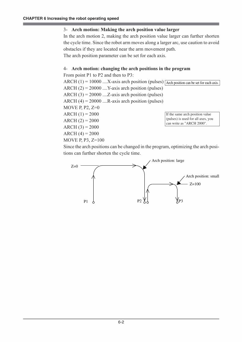
6-2
CHAPTER 6 Increasing the robot operating speed
3- Arch motion: Making the arch position value largerIn the arch motion 2, making the arch position value larger can further shorten the cycle time. Since the robot arm moves along a larger arc, use caution to avoid obstacles if they are located near the arm movement path.The arch position parameter can be set for each axis.
4- Arch motion: changing the arch positions in the programFrom point P1 to P2 and then to P3:ARCH (1) = 10000 ....X-axis arch position (pulses)ARCH (2) = 20000 ....Y-axis arch position (pulses)ARCH (3) = 20000 ....Z-axis arch position (pulses)ARCH (4) = 20000 ....R-axis arch position (pulses)MOVE P, P2, Z=0ARCH (1) = 2000 ARCH (2) = 2000ARCH (3) = 2000ARCH (4) = 2000MOVE P, P3, Z=100Since the arch positions can be changed in the program, optimizing the arch posi-tions can further shorten the cycle time.
Z=0
P1 P2 P3
Z=100
Arch position: large
Arch position: small
Arch position can be set for each axis.
If the same arch position value (pulses) is used for all axes, you can write as "ARCH 2000".

6-3
CHAPTER 6 Increasing the robot operating speed
(2) Increasing the speed with the WEIGHT statement[Also refer to:] Robot controller user's manual ("Robot parameters" – "Axis tip weight" in Chapter 4) Programming manual (WEIGHT statement in "10. Command statements".)
[Example]From P1 when chuck is open:WEIGHT 5 .........Changes the axis tip weight parameter to 5kg (no workpiece).MOVE P, P2, Z=0DO3 (0) = 1 ........Chuck closes.WEIGHT 10 .......Changes the axis tip weight parameter to 10kg (with workpiece).MOVE P, P3, Z=0
In the above program, the acceleration can be set to a higher level by reducing the axis tip weight parameter to 5kg while the chuck does not grip any workpiece, and then set to a lower level by changing the axis tip weight parameter to 10kg. Compared to programs using an axis tip weight parameter left set at 10kg, this method shortens the cycle time since the acceleration is increased.
P1
Z=0
Chuck opens.
Chuck 5kg
Workpiece 5kg
P3P2Chuck closes.
No workpiece Chuck is gripping workpiece.

6-4
CHAPTER 6 Increasing the robot operating speed
(3) Increasing the speed by the tolerance parameter[Also refer to:] Robot controller user's manual ("Axis parameters" – "Tolerance" in Chapter 4) Programming manual (TOLE statement in "10. Command statements".)
[Example]From P1 to P3 via P2TOLE (1) = 2048 ....X-axis tolerance (pulses) : Increases the tolerance.TOLE (2) = 2048 ....Y-axis tolerance (pulses) TOLE (3) = 2048 ....Z-axis tolerance (pulses) TOLE (4) = 2048 ....R-axis tolerance (pulses) MOVE P, P2TOLE (1) = 80 ........Returns the tolerance to the default value.TOLE (2) = 80TOLE (3) = 80TOLE (4) = 80MOVE, P, P3
When P2 is an escape point and does not need to be accurately positioned, setting the tolerance parameter to a larger value allows the robot arm to pass through P2 quickly. The larger the tolerance value for the positioning time, the shorter the cycle time will be.The maximum value of the tolerance parameter is 2048 (pulses) and the default is 80 (pulses).
P1
P2
P3
Tolerance can be set for each axis.If the same tolerance is used for all axes, you can write as "TOLE 2048".
If the same tolerance is used for all axes, you can write as "TOLE 80".
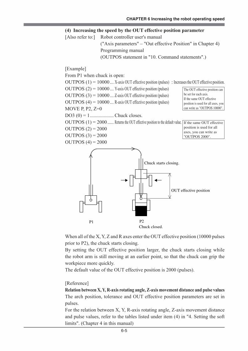
6-5
CHAPTER 6 Increasing the robot operating speed
(4) Increasing the speed by the OUT effective position parameter[Also refer to:] Robot controller user's manual ("Axis parameters" – "Out effective Position" in Chapter 4) Programming manual (OUTPOS statement in "10. Command statements".)
[Example]From P1 when chuck is open:OUTPOS (1) = 10000 ... X-axis OUT effective position (pulses) : Increases the OUT effective position.OUTPOS (2) = 10000 ... Y-axis OUT effective position (pulses) OUTPOS (3) = 10000 ... Z-axis OUT effective position (pulses)OUTPOS (4) = 10000 ... R-axis OUT effective position (pulses) MOVE P, P2, Z=0DO3 (0) = 1 ................... Chuck closes.OUTPOS (1) = 2000 ..... Returns the OUT effective position to the default value.OUTPOS (2) = 2000OUTPOS (3) = 2000OUTPOS (4) = 2000
P1 P2Chuck closed.
Chuck starts closing.
OUT effective position
When all of the X, Y, Z and R axes enter the OUT effective position (10000 pulses prior to P2), the chuck starts closing.By setting the OUT effective position larger, the chuck starts closing while the robot arm is still moving at an earlier point, so that the chuck can grip the workpiece more quickly.The default value of the OUT effective position is 2000 (pulses).
[Reference] Relation between X, Y, R-axis rotating angle, Z-axis movement distance and pulse valuesThe arch position, tolerance and OUT effective position parameters are set in pulses.For the relation between X, Y, R-axis rotating angle, Z-axis movement distance and pulse values, refer to the tables listed under item (4) in "4. Setting the soft limits". (Chapter 4 in this manual)
The OUT effective position can be set for each axis.If the same OUT effective position is used for all axes, you can write as "OUTPOS 10000".
If the same OUT effective position is used for all axes, you can write as "OUTPOS 2000".


CHAPTER 7
Specifications
1 Manipulator ..........................................................................................................7-11-1 Basic specification ...............................................................................................................7-11-2 External view and dimensions .............................................................................................7-21-3 Robot inner wiring diagram ...............................................................................................7-181-4 Wiring table .......................................................................................................................7-19
1-4-1 Robot cable wiring table ..................................................................................................... 7-19
1-4-2 Machine harness wiring table ............................................................................................. 7-22
1-4-3 Motor wiring table .............................................................................................................. 7-26
1-5 Maintenance parts ..............................................................................................................7-29


7-1
CHAPTER 7 Specifications
1 Manipulator
1-1 Basic specification
1.5kg
1.5kg (3.5m), 2.1kg (5m), 4.2kg (10m)
1.6kg 5.5kg 3.9kg 4.0kg 4.1kg6.5kg
8 cables
4x2
Class 10(0.1º level during suction)
30N /min
Class 10(0.1º level during suction)
5N /min –
–
R6YXC120
69.5mm
±113°
50.5mm
±139°
30mm
±360°
15W
13W
13W
13W
1.8m/s
0.5m/s
1700°/s
±0.01mm
±0.01mm
±0.006°
R6YXC150
99.5mm
±113°
50.5mm
±139°
30mm
±360°
15W
13W
13W
13W
2.1m/s
0.5m/s
1700°/s
±0.01mm
±0.01mm
±0.006°
R6YXC180
71mm
±120°
109mm
±140°
100mm
±360°
50W
30W
30W
30W
3.3m/s
0.7m/s
1700°/s
±0.01mm
±0.01mm
±0.004°
R6YXC220
111mm
±120°
109mm
±140°
100mm
±360°
50W
30W
30W
30W
3.4m/s
0.7m/s
1700°/s
±0.01mm
±0.01mm
±0.004°
R6YXG120
45mm
±125°
75mm
±145°
50mm
±360°
30W
30W
30W
30W
3.3m/s
0.9m/s
1700°/s
±0.005mm
±0.01mm
±0.004°
R6YXG150
75mm
±125°
75mm
±145°
50mm
±360°
30W
30W
30W
30W
3.4m/s
0.9m/s
1700°/s
±0.005mm
±0.01mm
±0.004°
R6YXG180
105mm
±125°
75mm
±145°
50mm
±360°
30W
30W
30W
30W
3.3m/s
0.9m/s
1700°/s
±0.005mm
±0.01mm
±0.004°
R6YXG220
111mm
±120°
109mm
±140°
100mm
±360°
50W
30W
30W
30W
3.4m/s
0.7m/s
1700°/s
±0.01mm
±0.01mm
±0.004°
Arm length
Rotation angle
Arm length
Rotation angle
Stroke
Rotation angle
X-axis
Y-axis
Z-axis
R-axis
XY resultant
Z-axis
R-axis
XY-axes
Z-axis
R-axis
X-axis
Y-axis
Z-axis
R-axis
Axis speci�-cations
Motor
Maximum speed
Repeatability *1
Payload
R-axis tolerable moment of inertia *2
User wiring
User tubing (Outer diameter)
Travel limit
Robot cable
Weight (Excluding robot cable *3)
Robot cable weight
Degree of cleanliness
Suction amount
0.9kg (2m), 1.5kg (3.5m), 2.1kg (5m),
4.2kg (10m)
0.5kg
0.002kgm2
1.0kg
0.01kgm2 (0.1kgfcms2)
6 cables
1.Soft limit 2.Mechanical limit (XYZ-axes)
Robot model
3.5m (option: 5m, 10m) 2m (option: 3.5m, 5m, 10m)
*1 At constant ambient temperature, measured when the robot arm was moved 7 times in the same direction.
Repeatable positioning accuracy = ± | Maximum value
2– Minimum value |
*2 There are limits to acceleration coefficient settings.
*3 The total robot weight is the sum of the robot body weight and the cable weight.
3x2
–
–
Position where the maximum sound pressure is measured
1.0m meter apart from the back of the robot, 1.6m height from the �oor surface.
1.0m apart from the back of the robot, 45º to the right
Maximum sound pressure level of the robot (when there is 10dB or larger difference from the back ground sound pressure level)
66.9dB
63.1dB
Robot model
R6YXG220, R6YXC180, R6YXC220
R6YXG120, R6YXG150, R6YXG180
Noise level

7-2
CHAPTER 7 Specifications
1-2 External view and dimensions
*2* Maximum 10 mm rise during Z-axis stopper origin setting
J.S.T. Mfg Co., Ltd. SM connector SMR-6V-B, pin BYM-001T-0.6 or SYM-001T-P0.6 (supplied)Use the YC12 crimping machine
User tubing 1 (φ3)
User tubing 2 (φ3)
Do not attach any wire or tube to this cable. Doing so may reduce positioning accuracy.
Use M4 bolt for installation
Suction tubing (φ3) for bellows
φ6 0-0.012
Cir clip
φ20
R16
φ32
φ42
30
08.416
374247
112
126
148
2±2Z-axis origin position
40
44
58.5 12893
R21
Connector for user wiring (No. 1 to 6 usable, socket contact)
50.5 69.5
534
0
15
28
88
151
125
143
247
42
7326
19 66
111425
50
Suction coupler (φ6) for X, Y and R axis joints
φ24
113
10
φ5
R15
Viewed from direction A
Connector for user wiring(No. 1 to 6 usable, socket contact)
J.S.T. Mfg Co., Ltd. SM connector SMR-6V-B, pin BYM-001T-0.6 or SYM-001T-P0.6 (supplied)Use the YC12 crimping machine
Fig. 7-1 R6YXC120

7-3
CHAPTER 7 Specifications
Working envelope
X, Y-axis origin positionX, Y-axis maximum movement position during X, Y-axis absolute reset stopper origin setting
Use M3 bolt for installation
*1
*2
113°
113°
111° 111°
139° 139°
R46
R50.5
R120
139°±4°
113°±4°
121°
143°
0
22
45
57.565.5
0
38.548
61
84
58
User tubing 1 (φ3)
User tubing 2 (φ3)
Suction tubing (φ6) for base interior
04.
5 9 134.5
9.5
170
M3 ground terminal
3 9399
24 30 35
4-φ4
70
6
Suction tubing (φ3) for R-axis bellows
* When carrying out X, Y-axis absolute reset stopper origin setting, move the X-axis to a position counterclockwise from this position and the Y-axis to a position clockwise.
* Take care to prevent interference between the end tool, robot and peripheral devices, etc.
NOTE1. Suction amount for suction coupler *1 : 25 Nl/min Suction amount lower than this level cannot maintain the degree of
cleanliness and higher than this level may damage the Z-axis bellows.2. Suction amount for suction couplers *2 : 25 Nl/min (Simultaneous suction
through two φ6 couplers is possible.) Suction amount lower than this level cannot maintain the degree of
cleanliness.3. Always set the maximum Z-axis rotating speed (axis parameter No. 37) to
"1500". If higher than this value, the degree of cleanliness cannot be maintained and the bellows might be damaged.

7-4
CHAPTER 7 Specifications
*2* Maximum 10 mm rise during Z-axis stopper origin setting
J.S.T. Mfg Co., Ltd. SM connector SMR-6V-B, pin BYM-001T-0.6 or SYM-001T-P0.6 (supplied)Use the YC12 crimping machine
User tubing 1 (φ3)
User tubing 2 (φ3)
Do not attach any wire or tube to this cable. Doing so may reduce positioning accuracy.
Use M4 bolt for installation
Suction tubing (φ3) for bellows
φ6 0-0.012
Cir clip
φ20
R16
φ32φ42
30
08.416
374247
112
126
148
2±2Z-axis origin position
40
44
58.5 12893
R21
Connector for user wiring (No. 1 to 6 usable, socket contact)
50.5 99.5
534
0
15
28
88
151
125
143
247
42
732619 66
96425
50
Suction coupler (φ6) for X, Y and R axis joints
φ24
113
10
φ5
R15
Viewed from direction A
Connector for user wiring(No. 1 to 6 usable, socket contact)
J.S.T. Mfg Co., Ltd. SM connector SMR-6V-B, pin BYM-001T-0.6 or SYM-001T-P0.6 (supplied)Use the YC12 crimping machine
Fig. 7-2 R6YXC150

7-5
CHAPTER 7 Specifications
Working envelope
X, Y-axis origin positionX, Y-axis maximum movement position during X, Y-axis absolute reset stopper origin setting
Use M3 bolt for installation
*1
*2
R150
R70
R50.5
113°
113°
139° 139°
139°±4°
113°±4°
121°
143°
0
22
45
57.565.5
0
38.548
61
84User tubing 1 (φ3)
User tubing 2 (φ3)
Suction tubing (φ6) for base interior
04.
5 9 134.5
9.5
170
M3 ground terminal
3 9399
24 30 35
4-φ4
70
6
Suction tubing (φ3) for R-axis bellows
* Take care to prevent interference between the end tool, robot and peripheral devices, etc.
* When carrying out X, Y-axis absolute reset stopper origin setting, move the X-axis to a position counterclockwise from this position and the Y-axis to a position clockwise.
NOTE1. Suction amount for suction coupler *1 : 25 Nl/min Suction amount lower than this level cannot maintain the degree of cleanliness and higher than this level may
damage the Z-axis bellows.2. Suction amount for suction couplers *2 : 25 Nl/min (Simultaneous suction through two φ6 couplers is possible.) Suction amount lower than this level cannot maintain the degree of cleanliness.3. Always set the maximum Z-axis rotating speed (axis parameter No. 37) to "1500". If higher than this value, the
degree of cleanliness cannot be maintained and the bellows might be damaged.
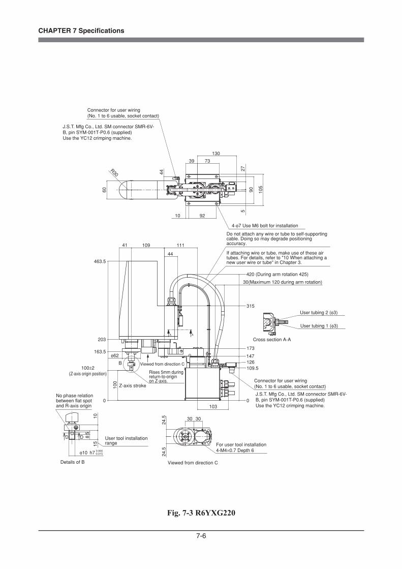
7-6
CHAPTER 7 Specifications
Connector for user wiring (No. 1 to 6 usable, socket contact)
R30
60
4439 73
130
27
90 105
5
4-φ7 Use M6 bolt for installation
10 92
41 109 111
44
463.5
203
163.5φ62
100
Z-axis stroke
A A
0
Cross section A-A
User tubing 2 (φ3)
User tubing 1 (φ3)
420 (During arm rotation 425)
30(Maximum 120 during arm rotation)
315
173
147126109.5
Connector for user wiring (No. 1 to 6 usable, socket contact)
0103
100±2(Z-axis origin position) Rises 5mm during
return-to-origin on Z-axis.
B
J.S.T. Mfg Co., Ltd. SM connector SMR-6V-B, pin SYM-001T-P0.6 (supplied)Use the YC12 crimping machine.
J.S.T. Mfg Co., Ltd. SM connector SMR-6V-B, pin SYM-001T-P0.6 (supplied)Use the YC12 crimping machine.
24.5
24.5
30 30
Viewed from direction C
For user tool installation4-M4×0.7 Depth 6
Viewed from direction C
Do not attach any wire or tube to self-supporting cable. Doing so may degrade positioning accuracy.
If attaching wire or tube, make use of these air tubes. For details, refer to "10 When attaching a new user wire or tube" in Chapter 3.
1015
φ10 h7 0.000-0.015
D D 85
No phase relation between flat spot and R-axis origin
User tool installation range
Details of B
Fig. 7-3 R6YXG220
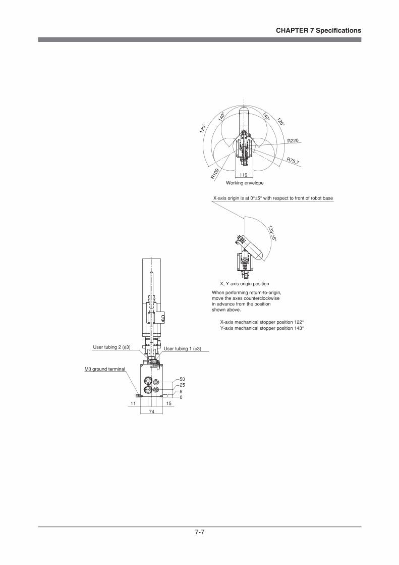
7-7
CHAPTER 7 Specifications
120°
140°
140° 120°
119
R220
R75.7
R10
9
133°±5°
74
11 15
502580
M3 ground terminal
User tubing 2 (φ3) User tubing 1 (φ3)
X-axis origin is at 0°±5° with respect to front of robot base
X, Y-axis origin position
Working envelope
When performing return-to-origin, move the axes counterclockwise in advance from the position shown above.
X-axis mechanical stopper position 122°Y-axis mechanical stopper position 143°
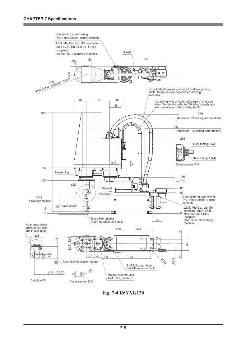
7-8
CHAPTER 7 Specifications
25
36
75 4538
φ53
32
0
6
105
146
322
50
0
67
105
116
239
316
80
B
A A
50
φ53
R25
138
27 20
22.5
22.5
41.5 90.5
43
4.5 123
2-5.
52-R3
1414
φ4
90.
0-0
.2
1015
φ10 h7
85
D D
0.000-0.015
Connector for user wiring (No. 1 to 8 usable, socket contact)
Z-axis stroke
Rises 5mm during return-to-origin on Z-axis.
Cross section A-A
User tubing 1 (φ4)
User tubing 2 (φ4)
Connector for user wiring (No. 1 to 8 usable, socket contact)
J.S.T. Mfg Co., Ltd. SM connector SMR-8V-B, pin SYM-001T-P0.6 (supplied)Use the YC12 crimping machine.
J.S.T. Mfg Co., Ltd. SM connector SMR-8V-B, pin SYM-001T-P0.6 (supplied)Use the YC12 crimping machine.
Viewed from
direction C
2-φ5.5 through-holeUse M5 mounting bolt.
R-axis dog
R30
(R-axis dog rotational radius)
47±2(Z-axis origin position)
(Maximum 322 during arm rotation)
(Maximum 120 during arm rotation)
Tapped hole for user4-M3×0.5, depth: 7
No phase relation between flat spot and R-axis origin
Details of B
User tool installation range
X-axis
Cross section D-D
Do not attach any wire or tube to self-supporting cable. Doing so may degrade positioning accuracy.
If attaching wire or tube, make use of these air tubes. For details, refer to "10 When attaching a new user wire or tube" in Chapter 3.
φ26
Fig. 7-4 R6YXG120

7-9
CHAPTER 7 Specifications
(43)
47
53
35
74
145°
145°
125°
125°
80
R12
0
46
R12
R46
R75
M3 ground terminal
User tubing 2 (φ4) User tubing 1 (φ4)
X, Y-axis origin is at ±5° with respect to front of robot base
Working envelope
When performing return-to-origin, move the axes counterclockwise in advance from the position shown above.
X-axis mechanical stopper position 128°Y-axis mechanical stopper position 148°

7-10
CHAPTER 7 Specifications
φ53
φ10φ4
25
36
75 7538
32
50
0
6
104
146
322
0
67
105
119
239
316
80
A A
B
50R25
138
27 20
22.5
22.5
41.5 90.5
4.5 123
43
2-5.
52-R3
1414
1510
h7 - 0.0150.000
85
D D
9-0
.20.0
Z-axis stroke
Rises 5mm during return-to-origin on Z-axis.
Cross section A-A
User tubing 1 (φ4)
User tubing 2 (φ4)
Connector for user wiring (No. 1 to 8 usable, socket contact)
Connector for user wiring (No. 1 to 8 usable, socket contact)
J.S.T. Mfg Co., Ltd. SM connector SMR-8V-B, pin SYM-001T-P0.6 (supplied)Use the YC12 crimping machine.
J.S.T. Mfg Co., Ltd. SM connector SMR-8V-B, pin SYM-001T-P0.6 (supplied)Use the YC12 crimping machine.
Viewed from
direction C
R-axis dog
R30
(R-axis dog rotational radius)
47±2(Z-axis origin position)
(Maximum 322 during arm rotation)
(Maximum 120 during arm rotation)
Tapped hole for user4-M3×0.5, depth: 7
No phase relation between flat spot and R-axis origin
Details of B
User tool installation range
X-axis
Cross section D-D
2-φ5.5 through-holeUse four M5 mounting bolts.
Do not attach any wire or tube to self-supporting cable. Doing so may degrade positioning accuracy.
If attaching wire or tube, make use of these air tubes. For details, refer to "10 When attaching a new user wire or tube" in Chapter 3.
φ26
Fig. 7-5 R6YXG150
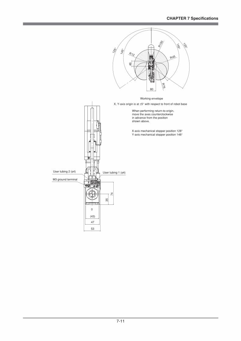
7-11
CHAPTER 7 Specifications
0
47
53
(43)
35
7412
5°
125°
145°
145°R15
0
80
46
R12R45
R75
M3 ground terminal
User tubing 2 (φ4) User tubing 1 (φ4)
X, Y-axis origin is at ±5° with respect to front of robot base
Working envelope
When performing return-to-origin, move the axes counterclockwise in advance from the position shown above.
X-axis mechanical stopper position 128°Y-axis mechanical stopper position 148°
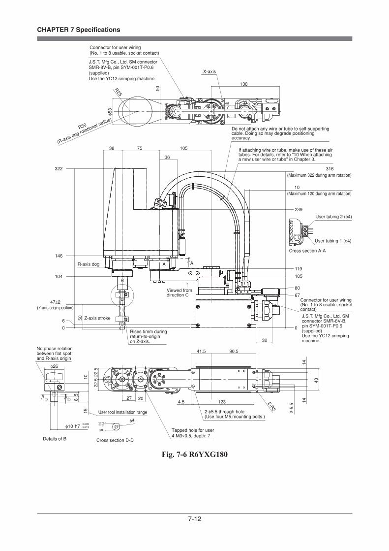
7-12
CHAPTER 7 Specifications
10
36
75 10538
32
50
0
6
104
146
322
0
67
105
119
239
316
80
A A
B
50
φ53
R25
138
27 20
22.5
22.5
41.5 90.5
4.5 123 2-R3
43
2-5.
5
1414
1510
φ10 h7 -0.0150.000
85
D D
φ4
9-0
.20.0
Cross section D-D
47±2(Z-axis origin position)
(Maximum 120 during arm rotation)
X-axis
Connector for user wiring (No. 1 to 8 usable, socket contact)
No phase relation between flat spot and R-axis origin
User tool installation range
Details of B
Z-axis stroke
Rises 5mm during return-to-origin on Z-axis.
Cross section A-A
User tubing 1 (φ4)
User tubing 2 (φ4)
Connector for user wiring (No. 1 to 8 usable, socket contact)
J.S.T. Mfg Co., Ltd. SM connector SMR-8V-B, pin SYM-001T-P0.6 (supplied)Use the YC12 crimping machine.
J.S.T. Mfg Co., Ltd. SM connector SMR-8V-B, pin SYM-001T-P0.6 (supplied)Use the YC12 crimping machine.
Viewed from direction C
R-axis dog
(Maximum 322 during arm rotation)
R30
(R-axis dog rotational radius)
2-φ5.5 through-hole(Use four M5 mounting bolts.)
Tapped hole for user4-M3×0.5, depth: 7
Do not attach any wire or tube to self-supporting cable. Doing so may degrade positioning accuracy.
If attaching wire or tube, make use of these air tubes. For details, refer to "10 When attaching a new user wire or tube" in Chapter 3.
φ26
Fig. 7-6 R6YXG180
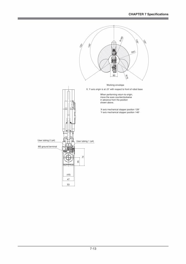
7-13
CHAPTER 7 Specifications
(43)
47
53
35
7412
5°
125°
145°
145°R18
0
80
R61
R75
M3 ground terminal
User tubing 2 (φ4) User tubing 1 (φ4)
X, Y-axis origin is at ±5° with respect to front of robot base
Working envelope
When performing return-to-origin, move the axes counterclockwise in advance from the position shown above.
X-axis mechanical stopper position 128°Y-axis mechanical stopper position 148°

7-14
CHAPTER 7 Specifications
(510 when arm is rotating)
711094445
223
484
335
500
0
110
183
28
0
105 ±2
A
Rises 5mm duringreturn-to-originon Z-axis.
100
(Z-a
xis
stro
ke)
(Z-axis origin position)
B
- 0.0210.000
12 (
Use
r to
ol in
stal
latio
n ra
nge)
Details of AScale 1 : 1
Plug
φ30 h7
φ55
0.000+0.015
Depth: 2φ10 H7
User tapped hole4-M3x0.5, depth: 6
Details of BScale 1 : 1
User tool installation tapped hole: 4-M3x0.5, depth: 6
The center line of the tool installation flange is offset within ±5° with respect to the R-axis origin position.
16 24
5.3 5.3
5.3
5.3
2626
User tubing 1 (Barb fitting φ3)
User tubing 2 (Barb fitting φ3)
15 92
74 90 105
R32.5
9-pin D-sub connector for user wiring(No. 1 to 8 usable, socket contact)
65
12540.5
4-φ7Use four M6 mounting bolts
Fig. 7-7 R6YXC180
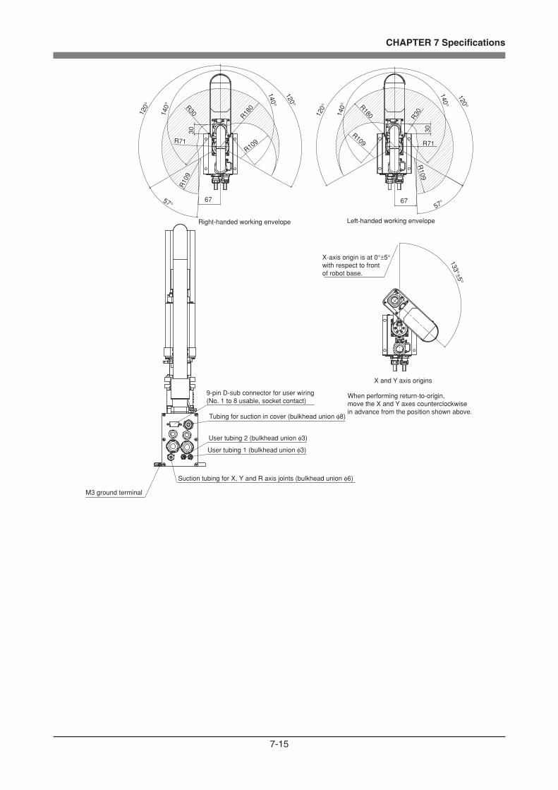
7-15
CHAPTER 7 Specifications
R109
Right-handed working envelope Left-handed working envelope
120°
57° 67
140°
140°
120°
120°
120°
140°
140°
57°67
R10
9
R71 R71
R30
R180 R180
133°±5°
X-axis origin is at 0°±5° with respect to front of robot base.
X and Y axis origins
When performing return-to-origin, move the X and Y axes counterclockwise in advance from the position shown above.
9-pin D-sub connector for user wiring(No. 1 to 8 usable, socket contact)
Tubing for suction in cover (bulkhead union φ8)
Suction tubing for X, Y and R axis joints (bulkhead union φ6)
M3 ground terminal
User tubing 2 (bulkhead union φ3)
User tubing 1 (bulkhead union φ3)
30
R109
30
R109
R30

7-16
CHAPTER 7 Specifications
- 0.0210.000
φ30 h7
φ55
9-pin D-sub connector for user wiring(No. 1 to 8 usable, socket contact)
4-φ7Use four M6 mounting bolts
R32.5
65
40.5125
74 90 105
15 92
(510 when arm is rotating)
Rises 5mm duringreturn-to-originon Z-axis.
12 (
Use
r to
ol in
stal
latio
n ra
nge)
Details of AScale 1 : 1
User tapped hole4-M3x0.5, depth: 6
5.3
5.3
2626
User tool installation tapped hole: 4-M3x0.5, depth: 6
The center line of the tool installation flange is offset within ±5° with respect to the R-axis origin position.
φ10 H7Depth: 2
5.3 5.3
16 24
Details of BScale 1 : 1
B
100
(Z-a
xis
stro
ke)
28
0
110
183
0
105 ±2
223
0.000+0.015
484
A
335
500
11110944
45
User tubing 2 (Barb fitting φ3)
User tubing 1 (Barb fitting φ3)
(Z-axis origin position)
Plug
Fig. 7-8 R6YXC220
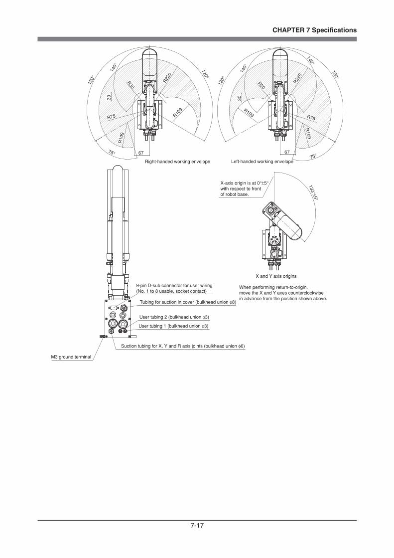
7-17
CHAPTER 7 Specifications
120°
140°
67
R109
75°Left-handed working envelope
140°
9-pin D-sub connector for user wiring(No. 1 to 8 usable, socket contact)
Tubing for suction in cover (bulkhead union φ8)
User tubing 2 (bulkhead union φ3)
User tubing 1 (bulkhead union φ3)
Suction tubing for X, Y and R axis joints (bulkhead union φ6)
M3 ground terminal
X-axis origin is at 0°±5° with respect to front of robot base.
133°±5°
120°
120°
120°
140°
6775°
Right-handed working envelope
X and Y axis origins
When performing return-to-origin, move the X and Y axes counterclockwise in advance from the position shown above.
R109 R109
R22
0
R30
30
R75R
109
R75
R22
0
R30
30

7-18
CHAPTER 7 Specifications
1-3 Robot inner wiring diagram
XY
ZMRM
XMYM
ZR
RORG RORG
ZBK ZBK
RP
RM
ZP
ZM
YP
YM
RP
RM
ZP
ZM
YP
YM
XP XP
ZBK ZBK
FG FG
XM XMYMYMZMZMRMRM
RORG RORGYP YP
ZP ZPRP RP
User wiring connector
User wiring connector
Robot cable
Round terminal
Round terminal
Round terminal
X-axis motor
X-axis resolver
Y-axis motorZ-axis motorR-axis motor
Z-axis brake
R-axis sensor
Y-axis resolver
Z-axis resolver
R-axis resolver
M3 ground terminal
User tubing
User tubing
User signal cable
Machine harness
User air tube
Brake is incorporated in Z-axis motor for R6YXG220.
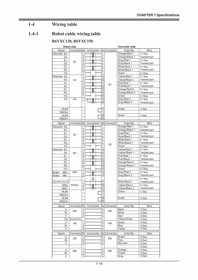
7-19
CHAPTER 7 Specifications
1-4 Wiring table
1-4-1 Robot cable wiring tableR6YXC120, R6YXC150
WV
R2
S1
ResolverS4
YM
XM
0.14sq
0.14sq
0.14sqTwisted pair
Twisted pair
Twisted pair
Twisted pair
Twisted pair
Twisted pair
Twisted pair
Twisted pair
Twisted pair
Twisted pair
Twisted pair
Twisted pair
Twisted pair
Twisted pair
Twisted pair
Twisted pair
4
U 0.5sq
0.5sq0.5sq0.5sq
0.5sq0.5sq
0.5sq
0.15sq
YP
0.15sq
XP
YM
XM
Resolver
VWU 2
3
R1R2FG
S2S4S1S3
S3
242322212019
6 65 5
7
4321
4321
R1
FG
S27
7
56
21
1
32
321
321
4FG
43
No WireColor/No.No
25
34
4
123
123
23
12
65
7
7S2
FG
R1
1234
1234
7
5566
192021222324
S3
S3S1S4S2
FGR2R1
32U
WV
Resolver
ZM
RM
ZR
ZP
0.15sq
RP
0.15sq
0.5sq
0.5sq0.5sq
0.5sq0.5sq0.5sq
0.5sq
25
S4Resolver
S1
R2
0.14sq
0.14sq
0.14sq
U
4
ZM
RM
1
28
VW
1FGFG
XY
110.3sq
10 0.3sq
18 0.14sq
29
HLIMGND24
HLIMGND24
2811
0.3sq
10 0.3sq
29
HLIMGND24
HLIMGND24
0.14sq
14
36
0.14sq
0.14sq
0.14sq
0.14sq
0.14sq
Brake MB - 2Brake MB+
160.14sqZBK
1 270.14sq
2 30 GND 3 ORG
310.14sqRORG
Robot side Controller side
Signal Connector Connection Connector
WireColor/No.Signal Connector Connection Connector
WireColor/No.Signal Connector Connection Connector
No WireColor/No.NoSignal Connector Connection Connector
No No
No No
Orange/Red 1Orange/Black 1
Orange/Red 2Orange/Black 2
Gray/Red 1Gray/Black 1
Gray/Red 2Gray/Black 2
Pink/Red 1Pink/Black 1
White/Red 1White/Black 1Green
Green
Green
Green
Green
Green
Yellow/Red 1Yellow/Black 1
Orange/Red 1Orange/Black 1
Orange/Red 2Orange/Black 2
Gray/Red 1Gray/Black 1
Gray/Red 2Gray/Black 2
Pink/Red 1Pink/Black 1
White/Red 1White/Black 1Green
Green
Yellow/Red 1Yellow/Black 1
BlackWhiteRedYellow/GreenGreenBlueYellow
BrownPinkSky blue
OrangePurpleGray
Round terminal
Origin position sensor 24V White/Red 2Yellow/Red 2Yellow/Black 2
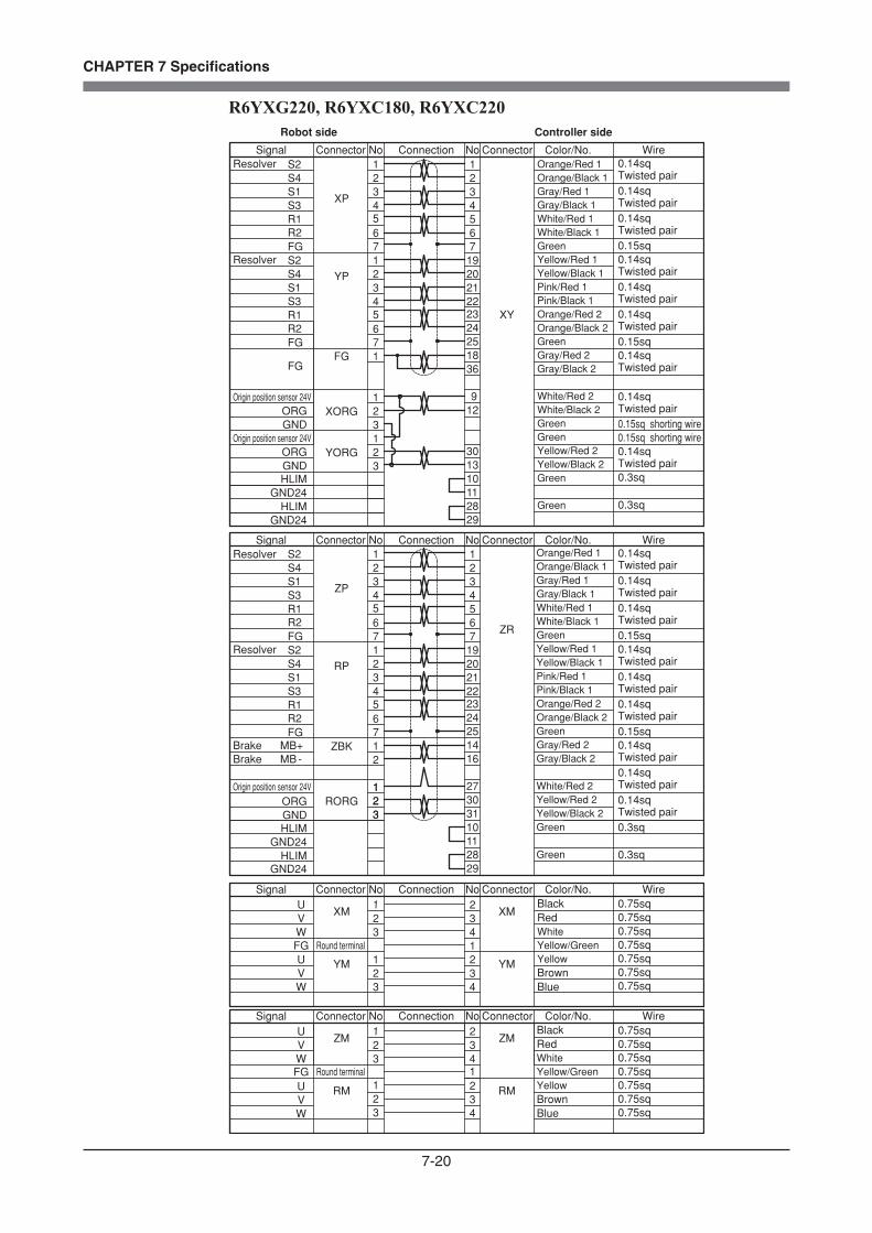
7-20
CHAPTER 7 Specifications
R6YXG220, R6YXC180, R6YXC220
VW
R2
S1
ResolverS4
YM
XM
0.14sqTwisted pair0.14sqTwisted pair
0.14sqTwisted pair
4
U
0.75sq
0.15sq
YP
0.15sq
XP
YM
XM
Resolver
WVU 2
3
R1R2FG
S2S4S1S3
S3
242322212019
6 65 5
7
4321
4321
R1
FG
S27
7
56
Signal
21
1
32
321
321
4
FG
43
ConnectionConnector No WireColor/No.ConnectorNo
Signal ConnectionConnector No WireColor/No.ConnectorNo
Signal ConnectionConnector No WireColor/No.ConnectorNo
Signal ConnectionConnector No WireColor/No.ConnectorNo
25
34
4
123
123
23
12
65
7
7S2
FG
R1
1234
1234
7
5566
192021222324
S3
S3S1S4S2
FGR2R1
32U
VW
Resolver
ZM
RM
ZR
ZP
0.15sq
RP
0.15sq
25
S4Resolver
S1
R2
0.14sqTwisted pair
0.14sqTwisted pair
0.14sqTwisted pair
U
4
Round terminal
ZM
RM
1
28
WV
1FGFG
110.3sq
10 0.3sq
18 0.14sqTwisted pair
29
HLIMGND24
HLIMGND24
2811
0.3sq
10 0.3sq
29
HLIMGND24
HLIMGND24
0.14sqTwisted pair
14
36
0.14sqTwisted pair0.14sqTwisted pair0.14sqTwisted pair
0.14sqTwisted pair
0.14sqTwisted pair
Brake MB - 2Brake MB+
160.14sqTwisted pair
ZBK
1 270.14sqTwisted pair
2 30 GND 3 ORG
310.14sqTwisted pair
RORGOrigin position sensor 24V 1
23
Origin position sensor 24V 1 92 12
GND 3 ORG XORG
Origin position sensor 24V 12 30
GND 3 ORG
13YORG 0.14sq
Twisted pair
0.15sq shorting wire
0.14sqTwisted pair
0.15sq shorting wire
FG Round terminal
0.75sq0.75sq0.75sq0.75sq0.75sq0.75sq
0.75sq
0.75sq0.75sq0.75sq
0.75sq0.75sq0.75sq
1
XY
Robot side Controller side
Orange/Red 1Orange/Black 1Gray/Red 1Gray/Black 1White/Red 1White/Black 1GreenYellow/Red 1Yellow/Black 1Pink/Red 1Pink/Black 1Orange/Red 2Orange/Black 2GreenGray/Red 2Gray/Black 2
White/Red 2White/Black 2GreenGreenYellow/Red 2Yellow/Black 2Green
Green
Orange/Red 1Orange/Black 1Gray/Red 1Gray/Black 1White/Red 1White/Black 1GreenYellow/Red 1Yellow/Black 1Pink/Red 1Pink/Black 1Orange/Red 2Orange/Black 2GreenGray/Red 2Gray/Black 2
White/Red 2Yellow/Red 2Yellow/Black 2Green
Green
BlackRedWhiteYellow/GreenYellowBrownBlue
BlackRedWhiteYellow/GreenYellowBrownBlue
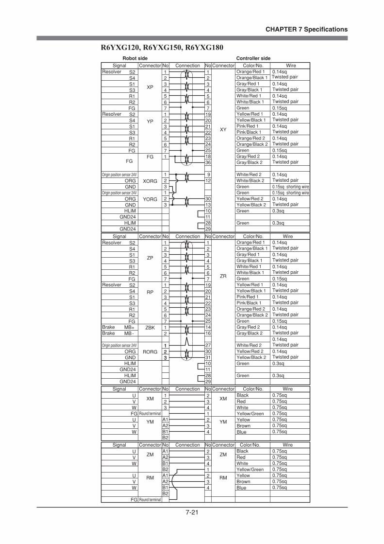
7-21
CHAPTER 7 Specifications
R6YXG120, R6YXG150, R6YXG180
VW
R2
S1S4
YM
XM
0.14sqTwisted pair0.14sqTwisted pair
0.14sq
4
U
0.75sq
0.15sq
YP
0.15sq
XP
YM
XM
WVU 2
3
R1R2FG
S2S4S1S3
S3
242322212019
6 65 5
7
4321
4321
R1
FG
S27
7
56
21
1
32
B2
A2A1
321
4
FG
43
25
34
4
23
12
65
7
7S2
FG
R1
1234
1234
7
5566
192021222324
S3
S3S1S4S2
FGR2R1
32U
VW
ZM
RM
ZR
ZP
0.15sq
RP
0.15sq
25
S4S1
R2
0.14sqTwisted pair
0.14sqTwisted pair
0.14sqTwisted pair
U
4
ZM
RM
1
28
WV
1FGFG
XY
110.3sq
10 0.3sq
18 0.14sqTwisted pair
29
HLIMGND24
HLIMGND24
2811
0.3sq
10 0.3sq
29
HLIMGND24
HLIMGND24
0.14sqTwisted pair
14
36
0.14sqTwisted pair0.14sqTwisted pair0.14sqTwisted pair
0.14sqTwisted pair
0.14sqTwisted pair
MB - 2 MB+
160.14sqTwisted pair
ZBK
1 270.14sqTwisted pair
2 30 GND 3 ORG
310.14sqTwisted pair
RORG123
1 92 12
GND 3 ORG XORG
12 30
GND 3 ORG
13YORG 0.14sq
Twisted pair
0.15sq shorting wire
0.14sqTwisted pair
0.15sq shorting wire
FG
0.75sq0.75sq0.75sq0.75sq0.75sq0.75sq
0.75sq
0.75sq0.75sq0.75sq
0.75sq0.75sq0.75sq
1
B1
B2
A2A1
B1
A1
B1B2
A2
Resolver
Twisted pairResolver
Signal ConnectionConnector No WireColor/No.ConnectorNo
Signal ConnectionConnector No WireColor/No.ConnectorNo
Signal ConnectionConnector No WireColor/No.ConnectorNo
Signal ConnectionConnector No WireColor/No.ConnectorNo
Resolver
Resolver
Round terminal
BrakeBrake
Origin position sensor 24V
Origin position sensor 24V
Origin position sensor 24V
Round terminal
Robot side Controller side
Orange/Red 1Orange/Black 1Gray/Red 1Gray/Black 1White/Red 1White/Black 1GreenYellow/Red 1Yellow/Black 1Pink/Red 1Pink/Black 1Orange/Red 2Orange/Black 2GreenGray/Red 2Gray/Black 2
White/Red 2White/Black 2GreenGreenYellow/Red 2Yellow/Black 2Green
Green
Orange/Red 1Orange/Black 1Gray/Red 1Gray/Black 1White/Red 1White/Black 1GreenYellow/Red 1Yellow/Black 1Pink/Red 1Pink/Black 1Orange/Red 2Orange/Black 2GreenGray/Red 2Gray/Black 2
White/Red 2Yellow/Red 2Yellow/Black 2Green
Green
BlackRedWhiteYellow/GreenYellowBrownBlue
BlackRedWhiteYellow/GreenYellowBrownBlue
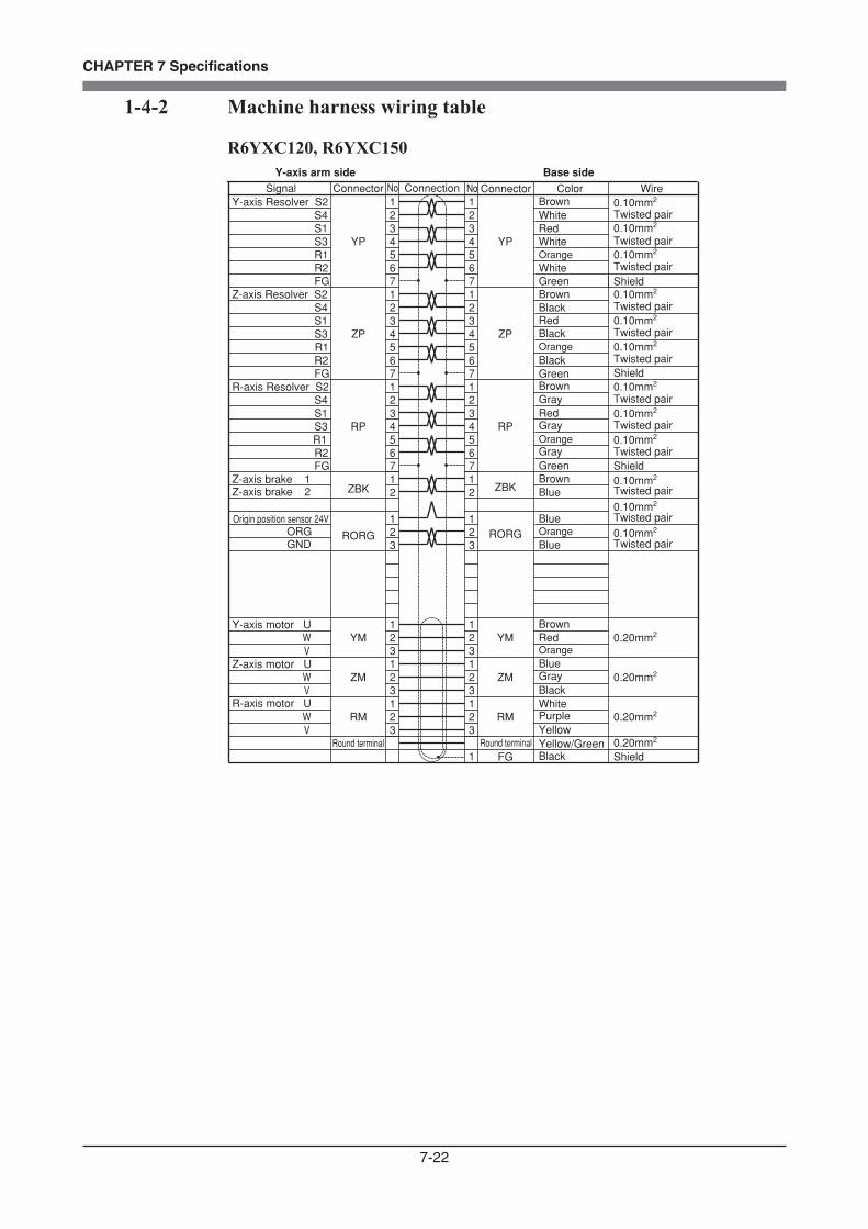
7-22
CHAPTER 7 Specifications
1-4-2 Machine harness wiring table
R6YXC120, R6YXC150
123
5
No Color WireNoConnector ConnectorConnection
123
5
Yellow
RP RP
67
67
W V
345
345
ZP ZP
67
67
R-axis Resolver S2 1234
1234
Signal
RM RM 0.20mm2
Y-axis motor U
Z-axis motor U
R-axis motor U
W V
YM 21
YM 0.20mm21233
W V
ZM 21
ZM 0.20mm21233
12 2
1
R1 S3 S1 S4
Y-axis Resolver S2
R2
12345
12345
YP YP
67
67 FG
Z-axis Resolver S2Shield
Shield
0.10mm2
Twisted pair0.10mm2
Twisted pair0.10mm2
Twisted pair
0.10mm2
Twisted pair0.10mm2
Twisted pair0.10mm2
Twisted pair
Shield
Shield
0.10mm2
Twisted pair0.10mm2
Twisted pair0.10mm2
Twisted pair
0.10mm2
Twisted pair
0.10mm2
Twisted pair0.10mm2
Twisted pair
Purple
Green
Green
Green
BlackYellow/Green
R1 S3 S1 S4
R2 FG
R1
FG R2
S4
S3 S1
Round terminal Round terminal 0.20mm2
1 FG
223 3
12
1
12
1Origin position sensor 24V
RORG RORG
Brown
Brown
Brown
Brown
Blue
Blue
Blue
Blue
BrownWhite
White
White
WhiteOrange
Orange
Orange
Orange
Orange
Red
Red
Red
Red
Black
Black
Black
Black
Gray
Gray
Gray
Gray
ZBKZBKZ-axis brake 2Z-axis brake 1
ORGGND
Y-axis arm side Base side
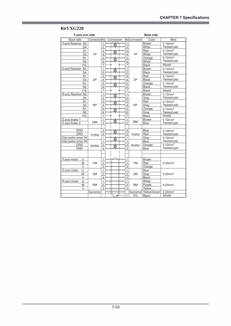
7-23
CHAPTER 7 Specifications
R6YXG220
S1
R2
R1
0.20mm2
FG R2
S4
123
5
No Connector Color WireNoConnector Connection
123
5
White
Yellow
RP RP
67
67
R-axis motor U W V
R1
S3345
345
ZP ZP
67
67
R-axis Resolver S2
S3
FG
S41234
1234
Base side
RM RM 0.20mm2
Y-axis motor U W V
YM 21
YM 0.20mm21233
BrownRed
Z-axis motor U W V
ZM 21
BlackZM 0.20mm2
1233
BlueGray
12 2
1
R1 S3 S1 S4
Y-axis Resolver S2
R2
12345
12345
0.10mm2
Twisted pair
0.10mm2
Twisted pair
0.10mm2
Twisted pairShield
YP YP
67
67 FG
S1
Z-axis Resolver S2
RedGray
Gray
Shield
0.10mm2
2
2
Twisted pair0.10mmTwisted pair0.10mmTwisted pair
Shield
0.10mm2
Twisted pair0.10mm2
Twisted pair0.10mm2
Twisted pair
Orange
WhiteBrown
Black
BrownBlack
Purple
Orange
Brown
Black
Black
Black
Yellow/GreenRound terminal Round terminal1 BlackFG Shield
YORGYORG
Blue
GrayRed
BlueBrown 0.10mm2
Twisted pair
221 1
12
3
12
GND 3ORG
Gray
Orange
Red
WhiteOrange
Black
WhiteRed
ZBKZBKZ-axis brake 2Z-axis brake 1
RORGRORG
Origin position sensor 24V Blue
BlueOrange22
3 3
1
GND
1ORG
Origin position sensor 24V
0.10mm2
Twisted pair0.10mm2
Twisted pair0.10mm2
Twisted pair
Y-axis arm side Base side

7-24
CHAPTER 7 Specifications
R6YXC180, R6YXC220
S1
R2
R1
0.20mm2
FG R2
S4
123
5
No Connector Color WireNoConnector Connection
123
56
87
1234
56
87
1234
5
White
White
White
Yellow
Yellow
Yellow
RP RP
67
67
R-axis motor
For user
U W V
R1
S3345
345
ZP ZP
67
67
R-axis Resolver S2
S3
FG
S41234
1234
Base side
RM RM
10 10
0.20mm2
Y-axis motor U W V
YM 21
YM 0.20mm21233
Brown
Red
Red
Red
Z-axis motor U W V
ZM 21
BlackZM 0.20mm2
1233
Blue
Blue
BlueGray
12 2
1
R1 S3 S1 S4
Y-axis Resolver S2
R2
12345
12345
0.10mm2
Twisted pair
0.10mm2
Twisted pair
0.10mm2
Twisted pairShield
YP YP
67
67 FG
S1
Z-axis Resolver S2
RedGray
Gray
Shield
0.10mm2
2
2
Twisted pair0.10mmTwisted pair0.10mmTwisted pair
Shield
0.10mm2
Twisted pair0.10mm2
Twisted pair0.10mm2
Twisted pair
Orange
WhiteBrown
Black
BrownBlack
Purple
Orange
Brown
Black
Black
Black
Yellow/GreenRound terminal Round terminal1 BlackFG Shield
YORGYORG
Blue
GrayRed
BlueBrown 0.10mm2
Twisted pair
221 1
12
3
12
GND 3ORG
Gray
Orange
Red
WhiteOrange
Black
WhiteRed
ZBKZBKZ-axis brake 2Z-axis brake 1
RORGRORG
Origin position sensor 24V Blue
BlueOrange22
3 3
1
GND
1ORG
Origin position sensor 24V
0.10mm2
Twisted pair0.10mm2
Twisted pair0.10mm2
Twisted pair
Y-axis arm side Base side
0.10mm20.10mm20.10mm20.10mm20.10mm20.10mm20.10mm20.10mm2
In φ4 air tube
In φ4 air tube
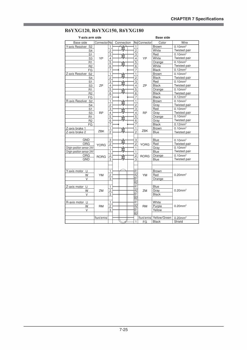
7-25
CHAPTER 7 Specifications
R6YXG120, R6YXG150, R6YXG180
S1
R2
R1
FG R2
S4
5
123
5RP RP
67
67
U W V
R1
S3345
345
ZP ZP
67
67
S2
S3
FG
S41234
1234
RM RM
U W V
YM 21
YMA1A2B13
U W V
ZM 21
ZM3
12 2
1
R1 S3 S1 S4
S2
R2
12345
12345
YP YP
67
67 FG
S1
S2
1 FG
YORGYORG 221 1
12
3
12
GND 3ORG
ZBKZBK
RORGRORG 223 3
1
GND
1ORG
B2A1A2B1B2
B1
A1A2
B2
No Connector Color WireNoConnector Connection
White
Yellow
R-axis motor
R-axis Resolver
Base side
Y-axis motor BrownRed
Z-axis motor
Black
BlueGray
Y-axis Resolver
Shield
Z-axis Resolver
RedGray
Gray
Twisted pair
Twisted pair
Twisted pair
Orange
WhiteBrown
Black
BrownBlack
Purple
Orange
Brown
Black
Black
Black
Yellow/GreenRound terminal Round terminalBlack
Blue
GrayRed
BlueBrown
Gray
Orange
Red
WhiteOrange
Black
WhiteRed
Z-axis brake 2Z-axis brake 1
Origin position sensor 24V Blue
BlueOrange
Origin position sensor 24V
Y-axis arm side Base side
0.20mm2
0.20mm2
0.20mm2
0.20mm2
0.10mm2
Twisted pair0.10mm2
Twisted pair0.10mm2
Twisted pair
0.10mm2
0.10mm2
0.10mm2
0.10mm2
Twisted pair0.10mm2
Twisted pair0.10mm2
Twisted pair
0.10mm2
Twisted pair
0.10mm2
Twisted pair0.10mm2
Twisted pair0.10mm2
Twisted pair
0.12mm2
0.12mm2
0.12mm2

7-26
CHAPTER 7 Specifications
1-4-3 Motor wiring table
R6YXC120, R6YXC150
Resolver
Motor
S2
S4
S1
S3
R1
R2
SHIELD
U
V
W
PE
No.
1
2
3
4
5
6
7
1
2
3
Connector
XP, YP, ZP, RP
XM, YM, ZM, RM
Red
Red
BlueYellow
Black
White
White
GreenBlack
Black
Signal Color Connection
Origin sensor wiring table
24V
ORGGND
Brown
Black
Blue
1
2
3
RORG
No.
Origin position sensor
Signal Color Connection Connector
Brake wiring table
Brake1
Brake2Yellow
Yellow
1
2ZBK
Signal No.Color Connection Connector

7-27
CHAPTER 7 Specifications
R6YXG220, R6YXC180, R6YXC220
Resolver
Motor
S2
S4
S1
S3
R1
R2
SHIELD
U
V
W
PE
No.
1
2
3
4
5
6
7
1
2
3
Round terminal
Connector
XP, YP, ZP, RP
XM, YM, ZM, RM
PE
Brown
Red
Blue
Red
White
Black
Black
Black
Signal Color Connection
Blue/Black
Brown/Black
Yellow/GreenBrake1
Brake2Yellow
Blue
1
2ZBK
Origin sensor wiring table
24V
ORGGND
Brown
Black
Blue
1
2
3
RORG
No.
Origin position sensor
Signal Color Connection Connector
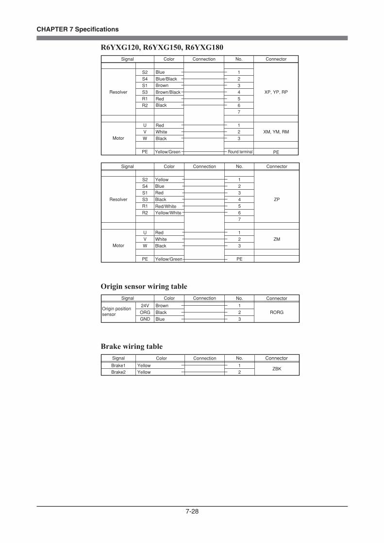
7-28
CHAPTER 7 Specifications
R6YXG120, R6YXG150, R6YXG180
Resolver
Motor
S2
S4
S1
S3
R1
R2
U
V
W
PE
No.
1
2
3
4
5
6
7
1
2
3
Round terminal
Connector
XP, YP, RP
XM, YM, RM
PE
Brown
Red
Blue
Red
White
Black
Black
Signal Color Connection
Blue/Black
Brown/Black
Yellow/Green
Resolver
Motor
S2
S4
S1
S3
R1
R2
U
V
W
PE
No.
1
2
3
4
5
6
7
1
2
3
PE
Connector
ZP
ZM
Red
Red/White
Red
BlueYellow
Black
WhiteBlack
Signal Color Connection
Yellow/Green
Yellow/White
Origin sensor wiring table
24V
ORGGND
Brown
Black
Blue
1
2
3
RORG
No.
Origin position sensor
Signal Color Connection Connector
Brake wiring table
Brake1
Brake2Yellow
Yellow
1
2ZBK
Signal No.Color Connection Connector
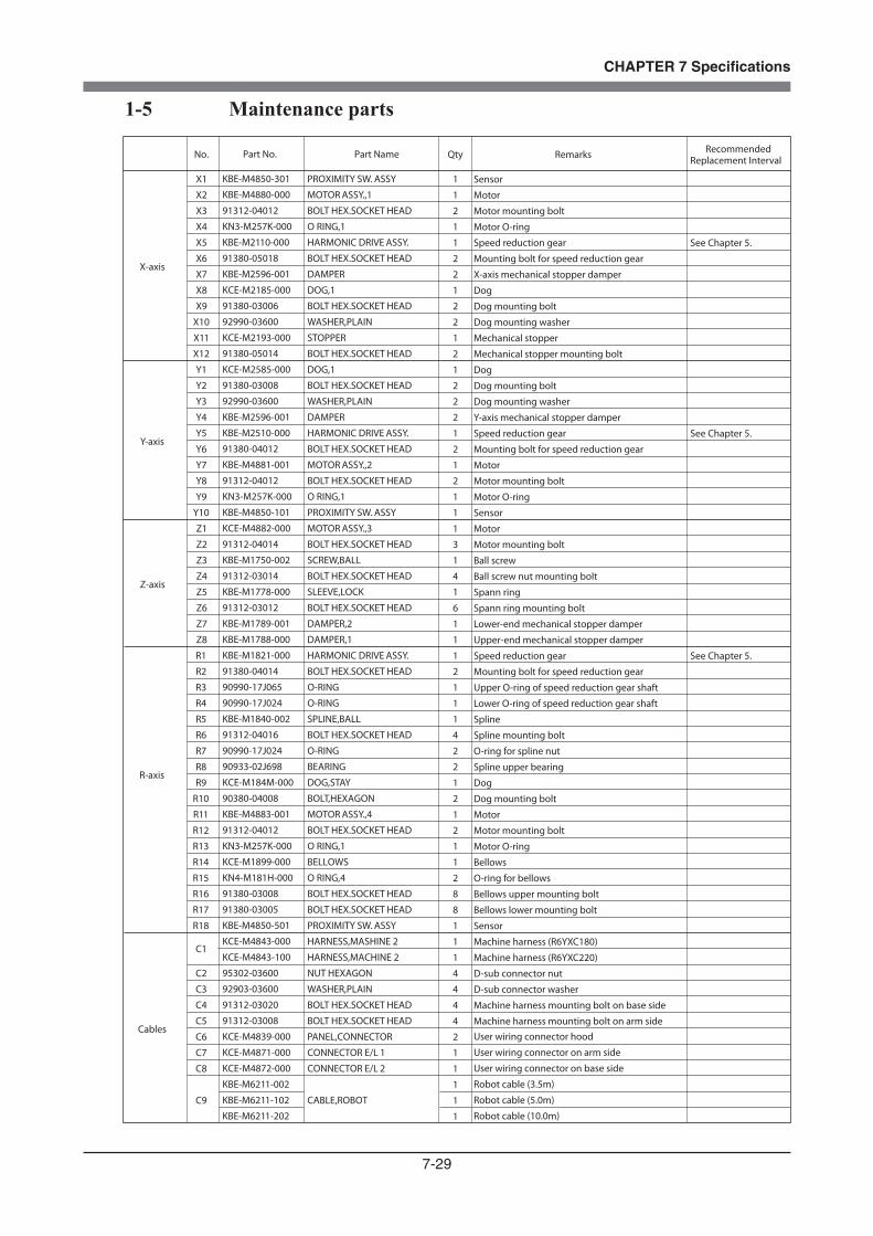
7-29
CHAPTER 7 Specifications
1-5 Maintenance parts
Part No.
KBE-M4850-301
KBE-M4880-000
91312-04012
KN3-M257K-000
KBE-M2110-000
91380-05018
KBE-M2596-001
KCE-M2185-000
91380-03006
92990-03600
KCE-M2193-000
91380-05014
KCE-M2585-000
91380-03008
92990-03600
KBE-M2596-001
KBE-M2510-000
91380-04012
KBE-M4881-001
91312-04012
KN3-M257K-000
KBE-M4850-101
KCE-M4882-000
91312-04014
KBE-M1750-002
91312-03014
KBE-M1778-000
91312-03012
KBE-M1789-001
KBE-M1788-000
KBE-M1821-000
91380-04014
90990-17J065
90990-17J024
KBE-M1840-002
91312-04016
90990-17J024
90933-02J698
KCE-M184M-000
90380-04008
KBE-M4883-001
91312-04012
KN3-M257K-000
KCE-M1899-000
KN4-M181H-000
91380-03008
91380-03005
KBE-M4850-501
KCE-M4843-000
KCE-M4843-100
95302-03600
92903-03600
91312-03020
91312-03008
KCE-M4839-000
KCE-M4871-000
KCE-M4872-000
KBE-M6211-002
KBE-M6211-102
KBE-M6211-202
Part Name
PROXIMITY SW. ASSY
MOTOR ASSY.,1
BOLT HEX.SOCKET HEAD
O RING,1
HARMONIC DRIVE ASSY.
BOLT HEX.SOCKET HEAD
DAMPER
DOG,1
BOLT HEX.SOCKET HEAD
WASHER,PLAIN
STOPPER
BOLT HEX.SOCKET HEAD
DOG,1
BOLT HEX.SOCKET HEAD
WASHER,PLAIN
DAMPER
HARMONIC DRIVE ASSY.
BOLT HEX.SOCKET HEAD
MOTOR ASSY.,2
BOLT HEX.SOCKET HEAD
O RING,1
PROXIMITY SW. ASSY
MOTOR ASSY.,3
BOLT HEX.SOCKET HEAD
SCREW,BALL
BOLT HEX.SOCKET HEAD
SLEEVE,LOCK
BOLT HEX.SOCKET HEAD
DAMPER,2
DAMPER,1
HARMONIC DRIVE ASSY.
BOLT HEX.SOCKET HEAD
O-RING
O-RING
SPLINE,BALL
BOLT HEX.SOCKET HEAD
O-RING
BEARING
DOG,STAY
BOLT,HEXAGON
MOTOR ASSY.,4
BOLT HEX.SOCKET HEAD
O RING,1
BELLOWS
O RING,4
BOLT HEX.SOCKET HEAD
BOLT HEX.SOCKET HEAD
PROXIMITY SW. ASSY
HARNESS,MASHINE 2
HARNESS,MACHINE 2
NUT HEXAGON
WASHER,PLAIN
BOLT HEX.SOCKET HEAD
BOLT HEX.SOCKET HEAD
PANEL,CONNECTOR
CONNECTOR E/L 1
CONNECTOR E/L 2
CABLE,ROBOT
X-axis
Y-axis
Z-axis
R-axis
Cables
No.
X1
X2
X3
X4
X5
X6
X7
X8
X9
X10
X11
X12
Y1
Y2
Y3
Y4
Y5
Y6
Y7
Y8
Y9
Y10
Z1
Z2
Z3
Z4
Z5
Z6
Z7
Z8
R1
R2
R3
R4
R5
R6
R7
R8
R9
R10
R11
R12
R13
R14
R15
R16
R17
R18
C1
C2
C3
C4
C5
C6
C7
C8
C9
Qty
1
1
2
1
1
2
2
1
2
2
1
2
1
2
2
2
1
2
1
2
1
1
1
3
1
4
1
6
1
1
1
2
1
1
1
4
2
2
1
2
1
2
1
1
2
8
8
1
1
1
4
4
4
4
2
1
1
1
1
1
Remarks
Sensor
Motor
Motor mounting bolt
Motor O-ring
Speed reduction gear
Mounting bolt for speed reduction gear
X-axis mechanical stopper damper
Dog
Dog mounting bolt
Dog mounting washer
Mechanical stopper
Mechanical stopper mounting bolt
Dog
Dog mounting bolt
Dog mounting washer
Y-axis mechanical stopper damper
Speed reduction gear
Mounting bolt for speed reduction gear
Motor
Motor mounting bolt
Motor O-ring
Sensor
Motor
Motor mounting bolt
Ball screw
Ball screw nut mounting bolt
Spann ring
Spann ring mounting bolt
Lower-end mechanical stopper damper
Upper-end mechanical stopper damper
Speed reduction gear
Mounting bolt for speed reduction gear
Upper O-ring of speed reduction gear shaft
Lower O-ring of speed reduction gear shaft
Spline
Spline mounting bolt
O-ring for spline nut
Spline upper bearing
Dog
Dog mounting bolt
Motor
Motor mounting bolt
Motor O-ring
Bellows
O-ring for bellows
Bellows upper mounting bolt
Bellows lower mounting bolt
Sensor
Machine harness (R6YXC180)
Machine harness (R6YXC220)
D-sub connector nut
D-sub connector washer
Machine harness mounting bolt on base side
Machine harness mounting bolt on arm side User wiring connector hood
User wiring connector on arm side
User wiring connector on base side
Robot cable (3.5m)
Robot cable (5.0m)
Robot cable (10.0m)
Recommended Replacement Interval
See Chapter 5.
See Chapter 5.
See Chapter 5.

7-30
CHAPTER 7 Specifications
R6YXG120
X1
X2,3,4
X5,6
X7
X8
X9
X10
X11,12,13
X14,15
Y1,2,3
Y4,5
Y6,7,8
Y9
Z1,2 Z3,4
Z5
Z6,7
Z8
Z9
Z10,11,12,13
R1,2,3
R4,5,6
R7
R8,9,10
R11,12,13
R14
C1
C2C3
C3
C4
R6YXG150, R6YXG180(Only parts differing from R6YXG120 are shown.)
X9
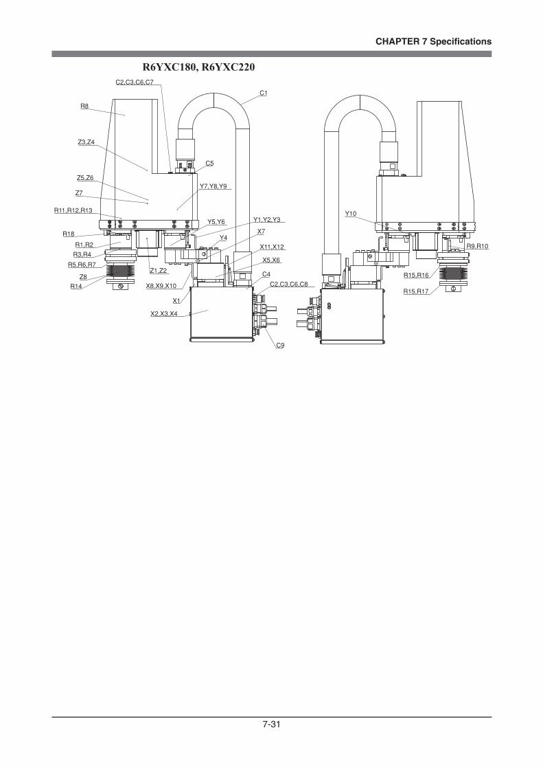
7-31
CHAPTER 7 Specifications
R6YXC180, R6YXC220C2,C3,C6,C7
R8
Z3,Z4
C1
C5
Y7,Y8,Y9Z5,Z6
Z7
R11,R12,R13
X1
X7Y4
Z8
R14
R18
C4
R5,R6,R7
R1,R2
R3,R4
Z1,Z2
X8,X9,X10
Y5,Y6 Y1,Y2,Y3
X11,X12
X5,X6
C2,C3,C6,C8
C9
X2,X3,X4
R15,R17
R15,R16
R9,R10
Y10

Revision History
A manual revision code appears as a suffix to the catalog number on the front cover of the manual.
Cat. No. I146E-EN-01
Revision code
The following table outlines the changes made to the manual during each revision. Page numbers refer to the previous revision.
Revision code Date Revised content
01 June 2010 Original production