castigliano's 2nd theorem
DESCRIPTION
structural analysisTRANSCRIPT
Chapter 2 Castigliano’s 2nd Theorem 2012
36
CHAPTER 2 (C01-P03)
CASTIGLIANO’S 2ND THEOREM
Learning Outcome
At the end of this chapter, students should:
1) Able to determine deformation for statically determinate beams by using Castigliano’s 2nd
theorem.
2) Able to determine deformation for statically determinate frames by using Castigliano’s 2nd
theorem.
3) Able to determine deformation for statically determinate trusses by using Castigliano’s 2nd
theorem.
Castigliano 2nd Theorem (C2T) for Beams and Frames
In 1879 Alberto Castigliano, an Italian railroad engineer, published a book in which he outlined a method
for determining the deflection or slope at a point in a structure.
The formula for the Castigliano 2nd Theorem for beam and frame deflections is as follows.
Where
∆ = external displacement of the point caused by the real loads acting on the beam or
frame.
P = external force applied to the beam of frame in the direction of ∆.
M = internal moment in the beam or frame, expressed as a function of x and caused by both
the force P and the real loads on the beam or frame.
E = modulus of elasticity of the material.
I = moment of inertia of cross-sectional area, computed about the neutral axis.
In a similar manner, if the slope at a point is to be determine, we must find the partial derivative of the
internal moment M with respect to an external couple moment M’ acting at the point i.e.
Chapter 2 Castigliano’s 2nd Theorem 2012
37
Procedure for analysis
The following step-by-step procedure can be used to determine the slopes and deflections of beams and
frames by Castigliano’s 2nd theorem.
1. Place a force P on the beam or frame at the point and in the direction of the desired displacement. If
the slope is to be determined, place a couple moment M’ at the point. It is assumed that both P and M’
have a variable magnitude.
2. Calculate reactions at the support in terms of P /M’ by using Equilibrium Equations.
3. For each segment of the beam/frame, determine the equation expressing the variation of the bending
moment along the length of the segment in terms of a position coordinate x. It is usually convenient
to consider the bending moments as positive in accordance with the beam sign convention.
4. Compute the partial derivative or for each coordinate x.
5. After M and or have been determined, assign P or M’ its numerical value if it has
replaced a real force or couple moment. Otherwise, set P or M’ equal to zero.
6. Apply Equation to determine the desired displacement or slope . If the resultant sum of all the
definite integral is positive, displacement or slope is in the same direction of P or M’.
Chapter 2 Castigliano’s 2nd Theorem 2012
38
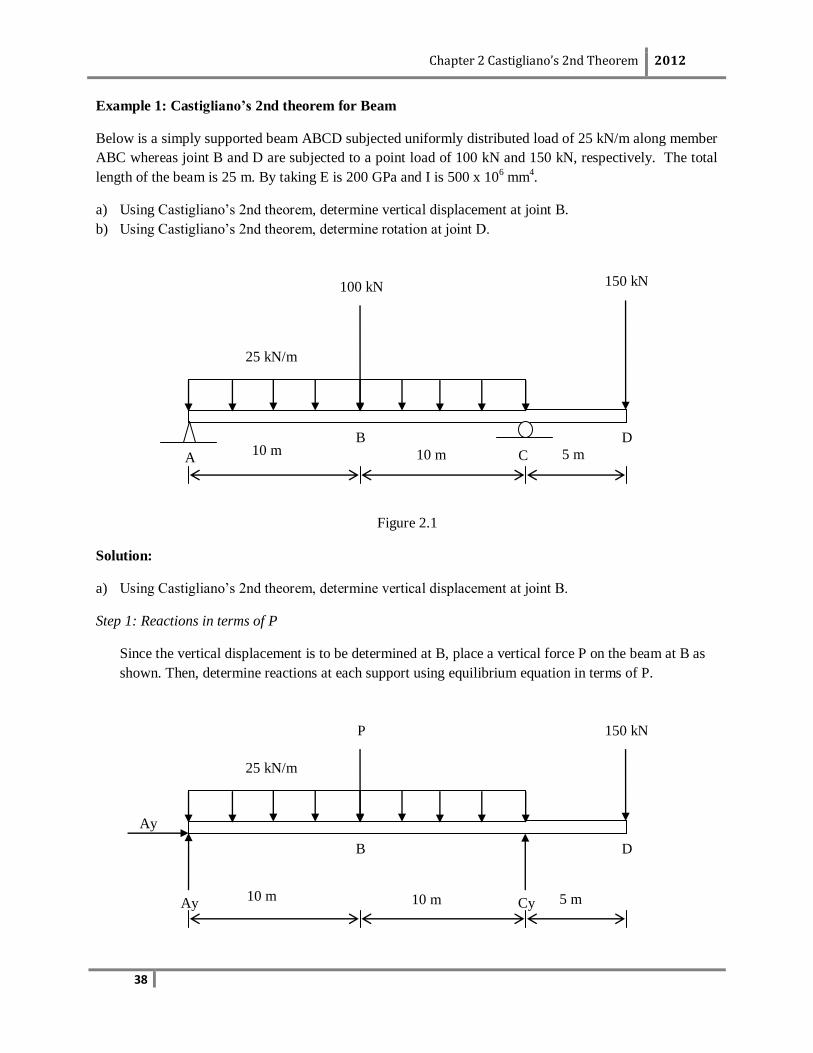
Example 1: Castigliano’s 2nd theorem for Beam
Below is a simply supported beam ABCD subjected uniformly distributed load of 25 kN/m along member
ABC whereas joint B and D are subjected to a point load of 100 kN and 150 kN, respectively. The total
length of the beam is 25 m. By taking E is 200 GPa and I is 500 x 106 mm
4.
a) Using Castigliano’s 2nd theorem, determine vertical displacement at joint B.
b) Using Castigliano’s 2nd theorem, determine rotation at joint D.
Figure 2.1
Solution:
a) Using Castigliano’s 2nd theorem, determine vertical displacement at joint B.
Step 1: Reactions in terms of P
Since the vertical displacement is to be determined at B, place a vertical force P on the beam at B as
shown. Then, determine reactions at each support using equilibrium equation in terms of P.
25 kN/m
150 kN
Ay
P
B
Cy
D
Ay
10 m 10 m 5 m
25 kN/m
150 kN
A
100 kN
B
C
D 10 m 10 m 5 m
Chapter 2 Castigliano’s 2nd Theorem 2012
39
Solve the reactions for the real beam/system using Equilibrium Equation.
∑MA = 0,
25(20)(20/2) + P(10) + 150(25) – Cy(20) = 0
Cy = (8750 + 10P) / 20
Cy = 437.5 + 0.5P
∑Fy = 0,
Ay + Cy - 25(20) - P - 150 = 0
Ay + (437.5 + 0.5P) - 25(20) - P - 150 = 0
Ay = 212.5 + 0.5P
∑Fx = 0,
Ax = 0 kN
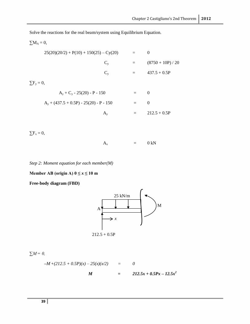
Step 2: Moment equation for each member(M)
Member AB (origin A) 0 ≤ x ≤ 10 m
Free-body diagram (FBD)
∑M = 0,
–M +(212.5 + 0.5P)(x) – 25(x)(x/2) = 0
M = 212.5x + 0.5Px – 12.5x2
25 kN/m
212.5 + 0.5P
A M
x
Chapter 2 Castigliano’s 2nd Theorem 2012
40
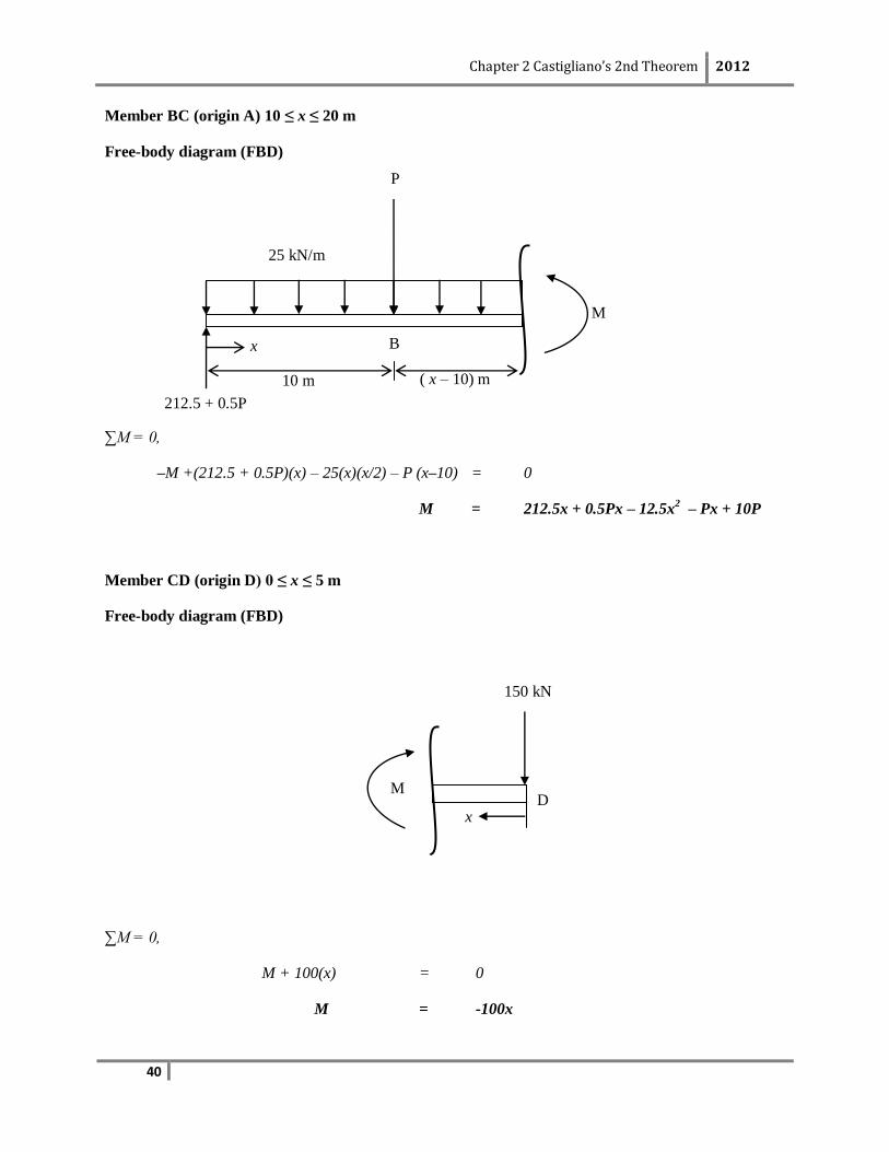
Member BC (origin A) 10 ≤ x ≤ 20 m
Free-body diagram (FBD)
∑M = 0,
–M +(212.5 + 0.5P)(x) – 25(x)(x/2) – P (x–10) = 0
M = 212.5x + 0.5Px – 12.5x2 – Px + 10P
Member CD (origin D) 0 ≤ x ≤ 5 m
Free-body diagram (FBD)
∑M = 0,
M + 100(x) = 0
M = -100x
x D
( x – 10) m 10 m
25 kN/m
P
B
212.5 + 0.5P
M
x
M
150 kN
Chapter 2 Castigliano’s 2nd Theorem 2012
41
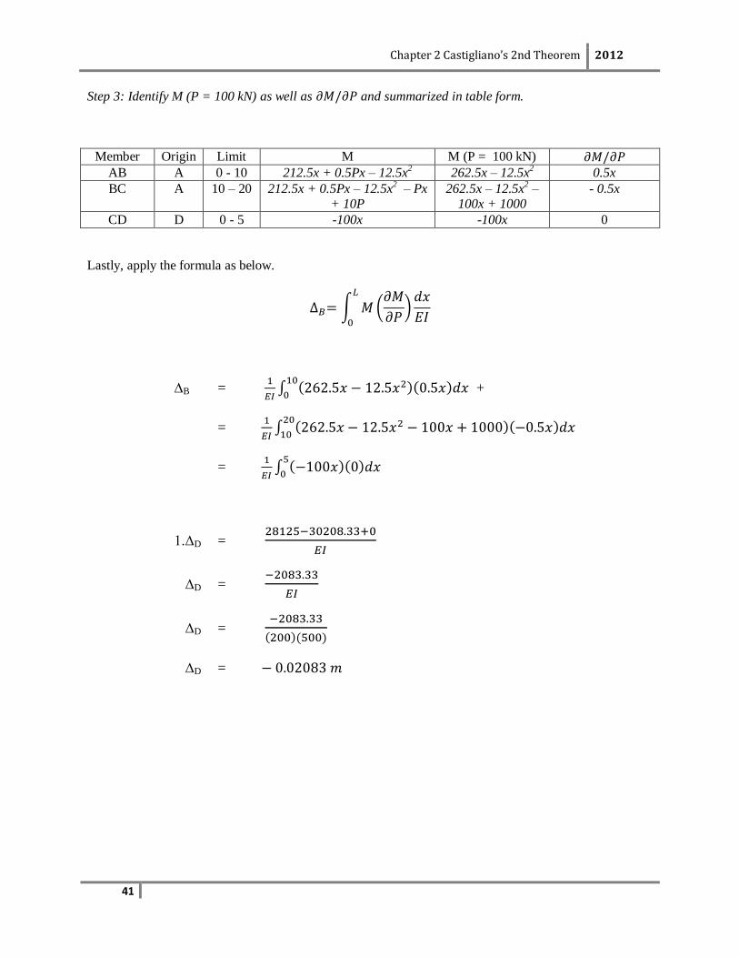
Step 3: Identify M (P = 100 kN) as well as and summarized in table form.
Member Origin Limit M M (P = 100 kN)
AB A 0 - 10 212.5x + 0.5Px – 12.5x2 262.5x – 12.5x
2 0.5x
BC A 10 – 20 212.5x + 0.5Px – 12.5x2 – Px
+ 10P 262.5x – 12.5x
2 –
100x + 1000 - 0.5x
CD D 0 - 5 -100x -100x 0
Lastly, apply the formula as below.
∆B =
+
=
=
1.∆D =
∆D =
∆D =
∆D =
Chapter 2 Castigliano’s 2nd Theorem 2012
42
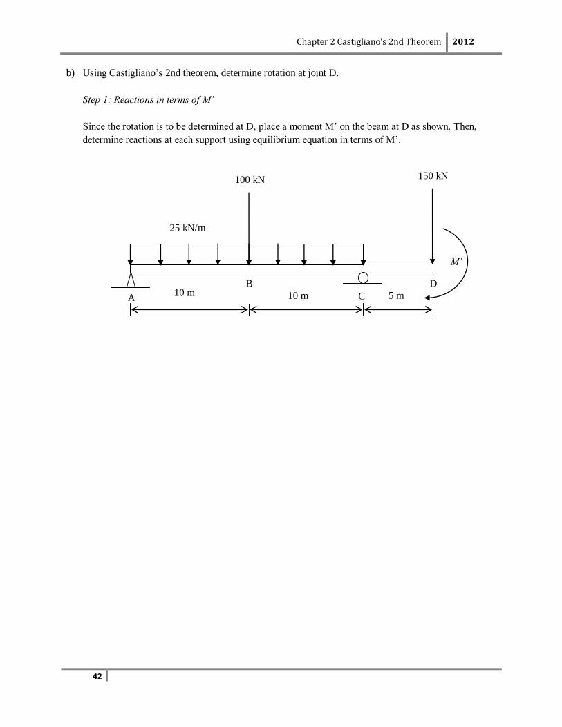
b) Using Castigliano’s 2nd theorem, determine rotation at joint D.
Step 1: Reactions in terms of M’
Since the rotation is to be determined at D, place a moment M’ on the beam at D as shown. Then,
determine reactions at each support using equilibrium equation in terms of M’.
M’
25 kN/m
150 kN
A
100 kN
B
C
D 10 m 10 m 5 m

Chapter 2 Castigliano’s 2nd Theorem 2012
43
Step 2: Moment equation for each member(M)
Chapter 2 Castigliano’s 2nd Theorem 2012
44
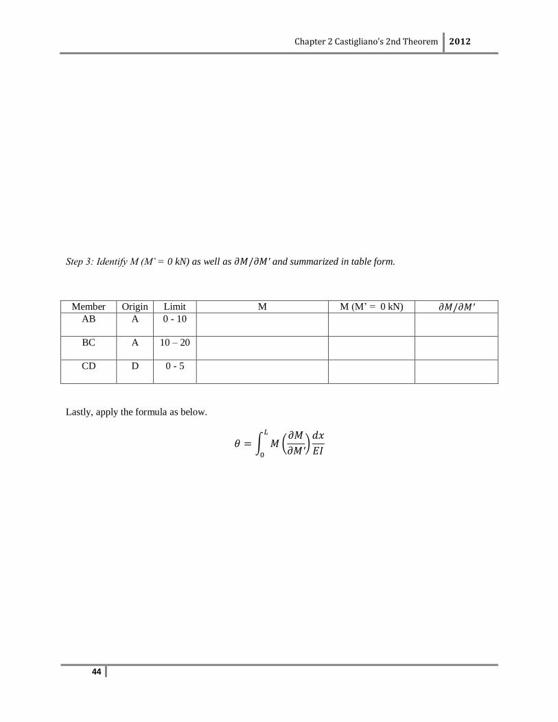
Step 3: Identify M (M’ = 0 kN) as well as and summarized in table form.
Member Origin Limit M M (M’ = 0 kN)
AB A 0 - 10
BC A 10 – 20
CD D 0 - 5
Lastly, apply the formula as below.
Chapter 2 Castigliano’s 2nd Theorem 2012
45
Self-Learning Exercise
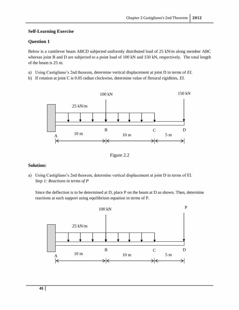
Question 1
Below is a cantilever beam ABCD subjected uniformly distributed load of 25 kN/m along member ABC
whereas joint B and D are subjected to a point load of 100 kN and 150 kN, respectively. The total length
of the beam is 25 m.
a) Using Castigliano’s 2nd theorem, determine vertical displacement at joint D in terms of EI.
b) If rotation at joint C is 0.05 radian clockwise, determine value of flexural rigidities, EI.
Figure 2.2
Solution:
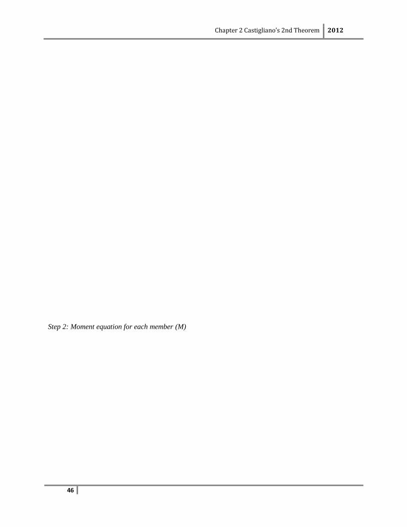
a) Using Castigliano’s 2nd theorem, determine vertical displacement at joint D in terms of EI.
Step 1: Reactions in terms of P
Since the deflection is to be determined at D, place P on the beam at D as shown. Then, determine
reactions at each support using equilibrium equation in terms of P.
25 kN/m
150 kN
A
100 kN
B C D 10 m 10 m 5 m
25 kN/m
P
A
100 kN
B C D 10 m 10 m 5 m
Chapter 2 Castigliano’s 2nd Theorem 2012
46
Step 2: Moment equation for each member (M)
Chapter 2 Castigliano’s 2nd Theorem 2012
47
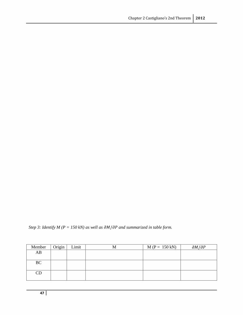
Step 3: Identify M (P = 150 kN) as well as and summarized in table form.
Member Origin Limit M M (P = 150 kN)
AB
BC
CD
Chapter 2 Castigliano’s 2nd Theorem 2012
48
Lastly, apply the formula as below.

Chapter 2 Castigliano’s 2nd Theorem 2012
49
b) If rotation at joint C is 0.05 radian clockwise, determine value of flexural rigidities, EI.
Chapter 2 Castigliano’s 2nd Theorem 2012
50
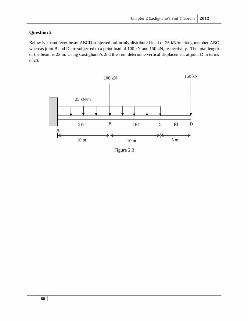
Question 2
Below is a cantilever beam ABCD subjected uniformly distributed load of 25 kN/m along member ABC
whereas joint B and D are subjected to a point load of 100 kN and 150 kN, respectively. The total length
of the beam is 25 m. Using Castigliano’s 2nd theorem determine vertical displacement at joint D in terms
of EI.
Figure 2.3
25 kN/m
150 kN
A
100 kN
B C D 2EI
10 m 5 m 10 m
2EI EI
Chapter 2 Castigliano’s 2nd Theorem 2012
51
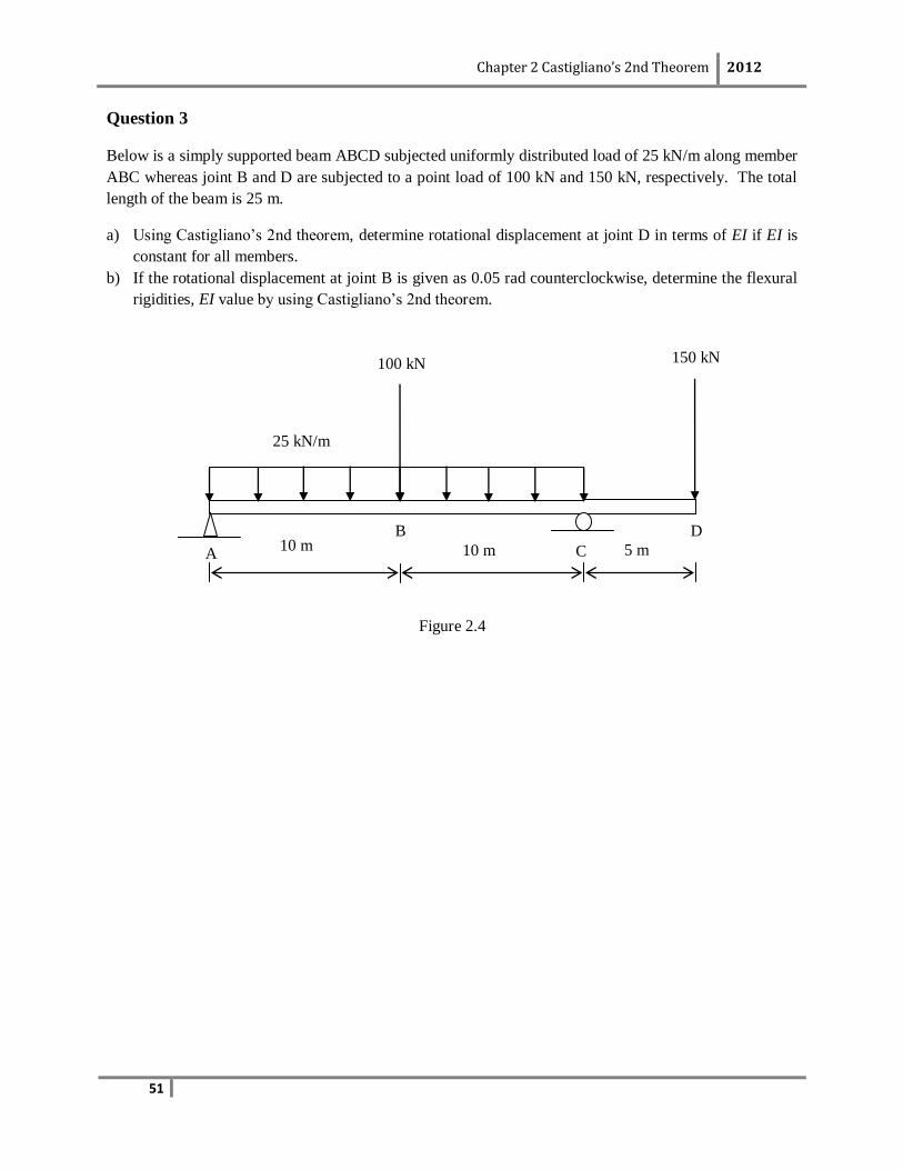
Question 3
Below is a simply supported beam ABCD subjected uniformly distributed load of 25 kN/m along member
ABC whereas joint B and D are subjected to a point load of 100 kN and 150 kN, respectively. The total
length of the beam is 25 m.
a) Using Castigliano’s 2nd theorem, determine rotational displacement at joint D in terms of EI if EI is
constant for all members.
b) If the rotational displacement at joint B is given as 0.05 rad counterclockwise, determine the flexural
rigidities, EI value by using Castigliano’s 2nd theorem.
Figure 2.4
25 kN/m
150 kN
A
100 kN
B
C
D 10 m 10 m 5 m
Chapter 2 Castigliano’s 2nd Theorem 2012
52
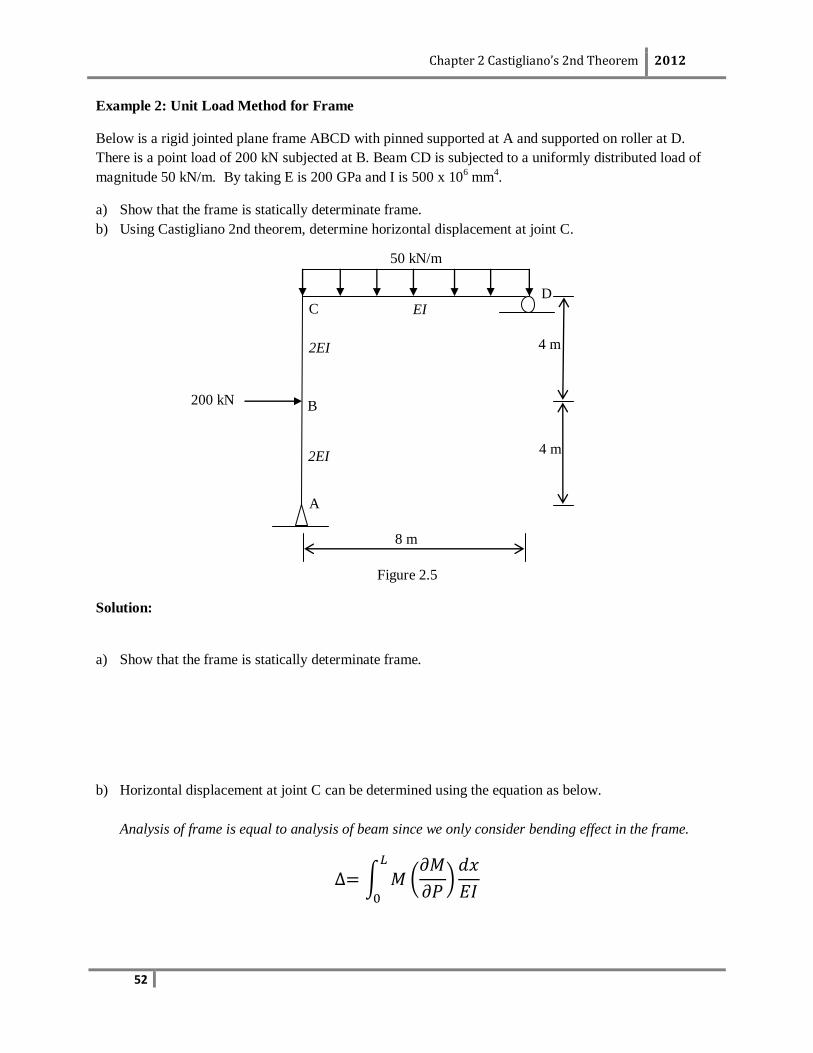
Example 2: Unit Load Method for Frame
Below is a rigid jointed plane frame ABCD with pinned supported at A and supported on roller at D.
There is a point load of 200 kN subjected at B. Beam CD is subjected to a uniformly distributed load of
magnitude 50 kN/m. By taking E is 200 GPa and I is 500 x 106 mm
4.
a) Show that the frame is statically determinate frame.
b) Using Castigliano 2nd theorem, determine horizontal displacement at joint C.
Figure 2.5
Solution:
a) Show that the frame is statically determinate frame.
b) Horizontal displacement at joint C can be determined using the equation as below.
Analysis of frame is equal to analysis of beam since we only consider bending effect in the frame.
EI
2EI
2EI
4 m
4 m
8 m
50 kN/m
200 kN
A
D
B
C
Chapter 2 Castigliano’s 2nd Theorem 2012
53
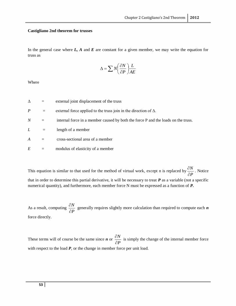
Castigliano 2nd theorem for trusses
In the general case where L, A and E are constant for a given member, we may write the equation for
truss as
AE
L
P
NN
Where
Δ = external joint displacement of the truss
P = external force applied to the truss join in the direction of Δ.
N = internal force in a member caused by both the force P and the loads on the truss.
L = length of a member
A = cross-sectional area of a member
E = modulus of elasticity of a member
This equation is similar to that used for the method of virtual work, except n is replaced byP
N
. Notice
that in order to determine this partial derivative, it will be necessary to treat P as a variable (not a specific
numerical quantity), and furthermore, each member force N must be expressed as a function of P.
As a result, computing P
N
generally requires slightly more calculation than required to compute each n
force directly.
These terms will of course be the same since n or P
N
is simply the change of the internal member force
with respect to the load P, or the change in member force per unit load.
Chapter 2 Castigliano’s 2nd Theorem 2012
54
Procedure for Analysis
The following procedure provides a method that may be used to determine the displacement of any joint
of a truss using Castigliano’s 2nd theorem.
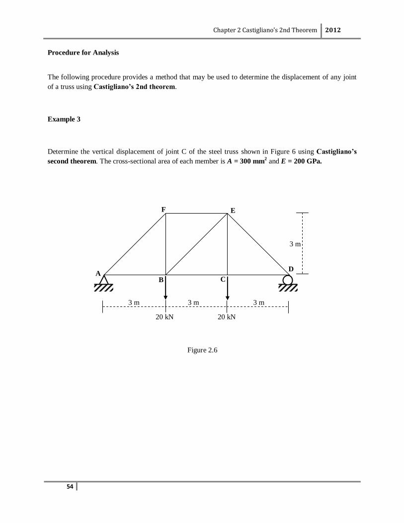
Example 3
Determine the vertical displacement of joint C of the steel truss shown in Figure 6 using Castigliano’s
second theorem. The cross-sectional area of each member is A = 300 mm2 and E = 200 GPa.
Figure 2.6
F E
D
C B A
20 kN 20 kN
3 m 3 m 3 m
3 m
Chapter 2 Castigliano’s 2nd Theorem 2012
55
Solution:
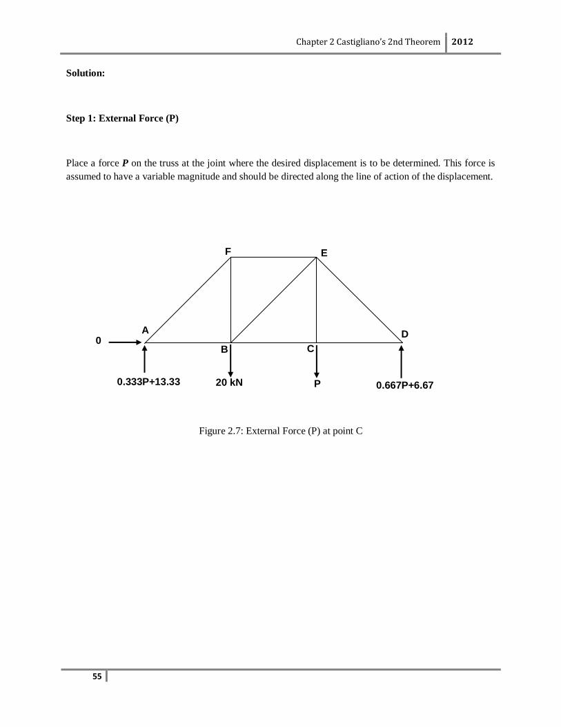
Step 1: External Force (P)
Place a force P on the truss at the joint where the desired displacement is to be determined. This force is
assumed to have a variable magnitude and should be directed along the line of action of the displacement.
Figure 2.7: External Force (P) at point C
0.667P+6.67
0
F E
D
C B
A
P 20 kN 0.333P+13.33
Chapter 2 Castigliano’s 2nd Theorem 2012
56
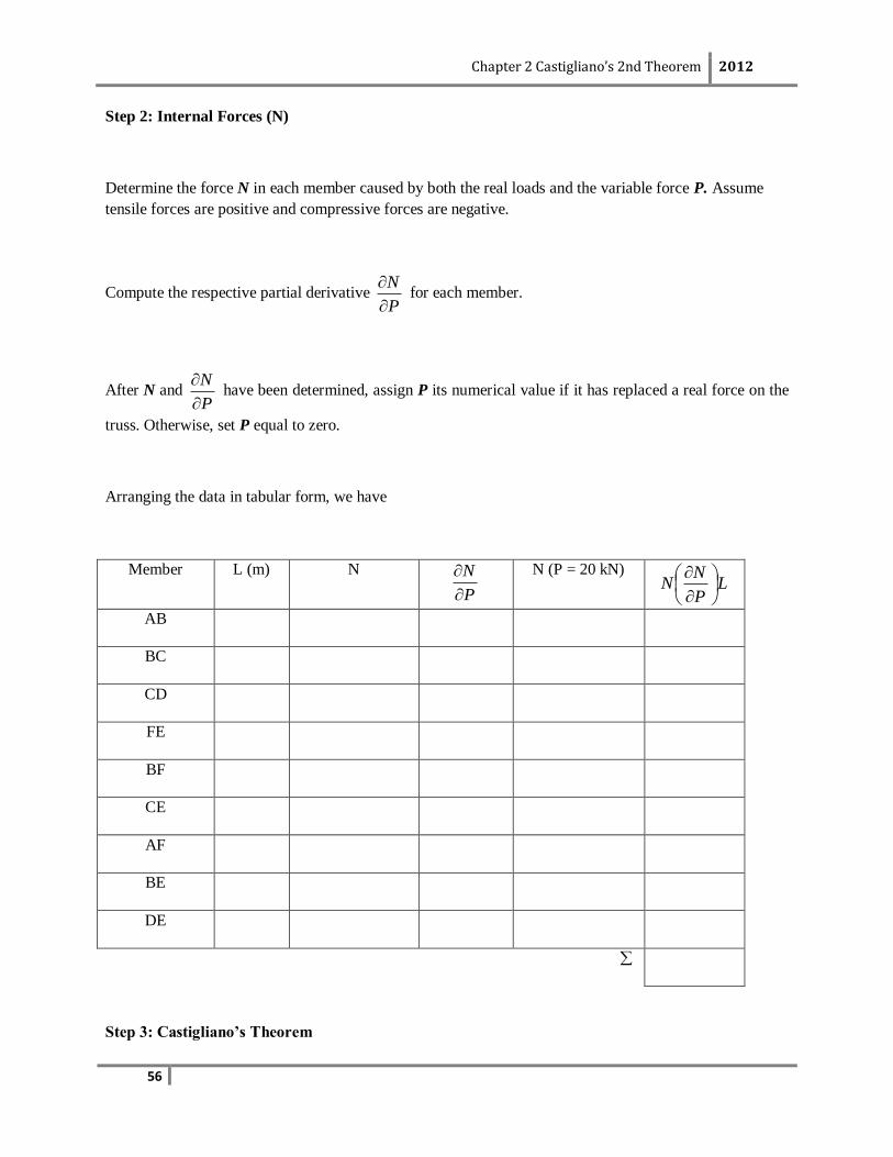
Step 2: Internal Forces (N)
Determine the force N in each member caused by both the real loads and the variable force P. Assume
tensile forces are positive and compressive forces are negative.
Compute the respective partial derivative P
N
for each member.
After N and P
N
have been determined, assign P its numerical value if it has replaced a real force on the
truss. Otherwise, set P equal to zero.
Arranging the data in tabular form, we have
Member L (m) N
P
N
N (P = 20 kN) L
P
NN
AB
BC
CD
FE
BF
CE
AF
BE
DE
Step 3: Castigliano’s Theorem
Chapter 2 Castigliano’s 2nd Theorem 2012
57
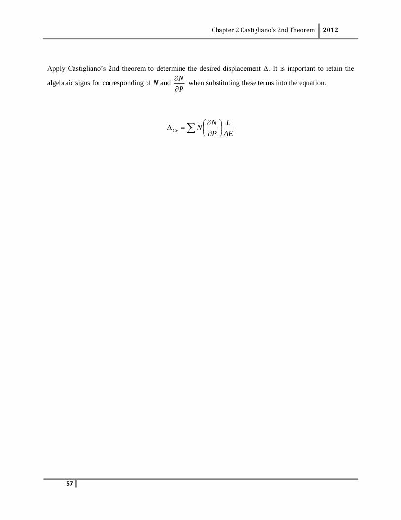
Apply Castigliano’s 2nd theorem to determine the desired displacement Δ. It is important to retain the
algebraic signs for corresponding of N and P
N
when substituting these terms into the equation.
AE
L
P
NNCv
Chapter 2 Castigliano’s 2nd Theorem 2012
58
Self Learning Exercise
Question 4
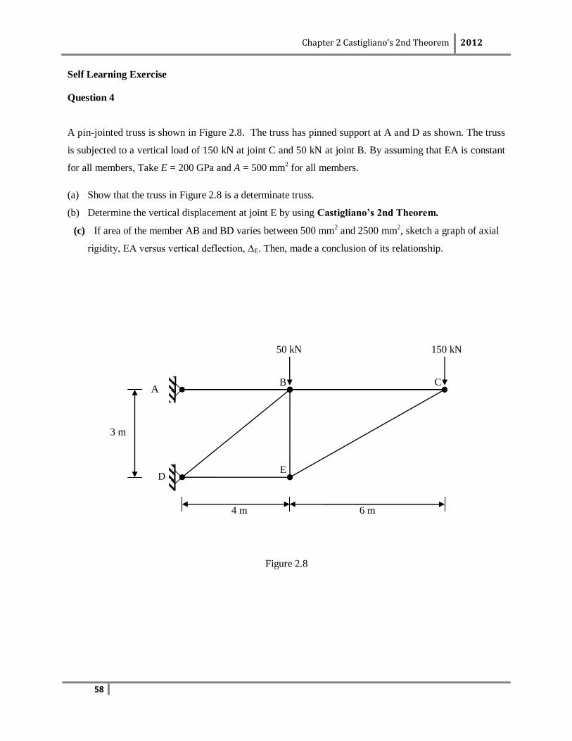
A pin-jointed truss is shown in Figure 2.8. The truss has pinned support at A and D as shown. The truss
is subjected to a vertical load of 150 kN at joint C and 50 kN at joint B. By assuming that EA is constant
for all members, Take E = 200 GPa and A = 500 mm2 for all members.
(a) Show that the truss in Figure 2.8 is a determinate truss.
(b) Determine the vertical displacement at joint E by using Castigliano’s 2nd Theorem.
(c) If area of the member AB and BD varies between 500 mm2 and 2500 mm
2, sketch a graph of axial
rigidity, EA versus vertical deflection, ∆E. Then, made a conclusion of its relationship.
Figure 2.8
4 m 6 m
C A
E D
B
150 kN 50 kN
3 m
Chapter 2 Castigliano’s 2nd Theorem 2012
59
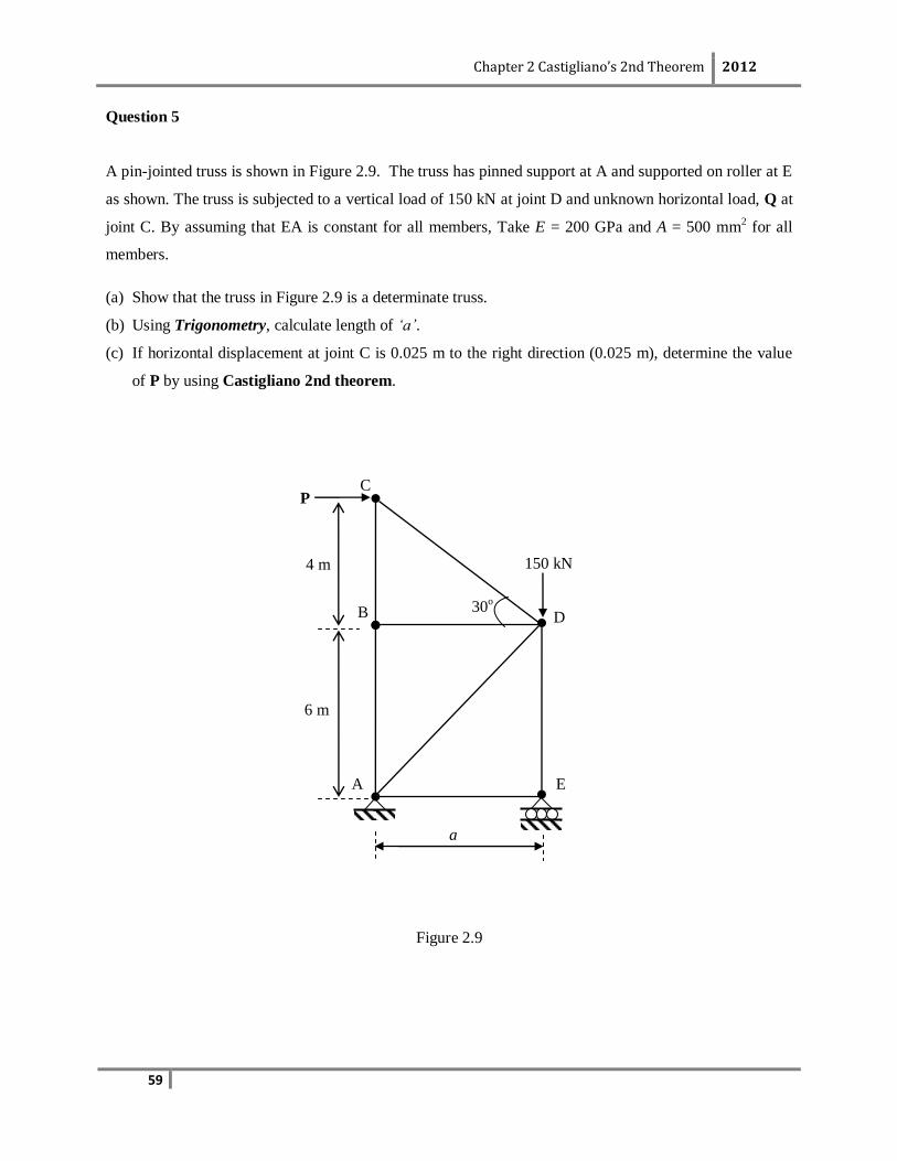
Question 5
A pin-jointed truss is shown in Figure 2.9. The truss has pinned support at A and supported on roller at E
as shown. The truss is subjected to a vertical load of 150 kN at joint D and unknown horizontal load, Q at
joint C. By assuming that EA is constant for all members, Take E = 200 GPa and A = 500 mm2 for all
members.
(a) Show that the truss in Figure 2.9 is a determinate truss.
(b) Using Trigonometry, calculate length of ‘a’.
(c) If horizontal displacement at joint C is 0.025 m to the right direction (0.025 m), determine the value
of P by using Castigliano 2nd theorem.
Figure 2.9
a
4 m
6 m
C
A E
D B
150 kN
P
30o
Chapter 2 Castigliano’s 2nd Theorem 2012
60
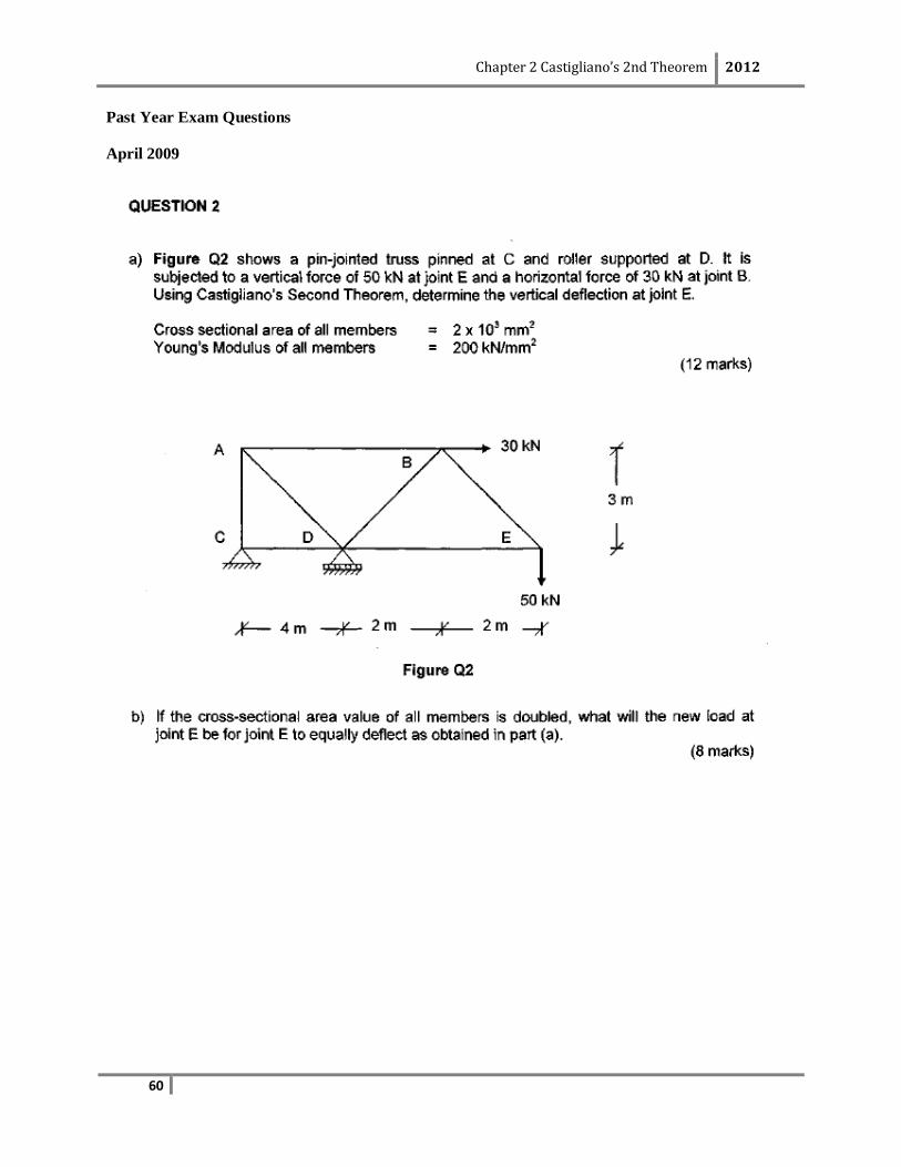
Past Year Exam Questions
April 2009
Chapter 2 Castigliano’s 2nd Theorem 2012
61
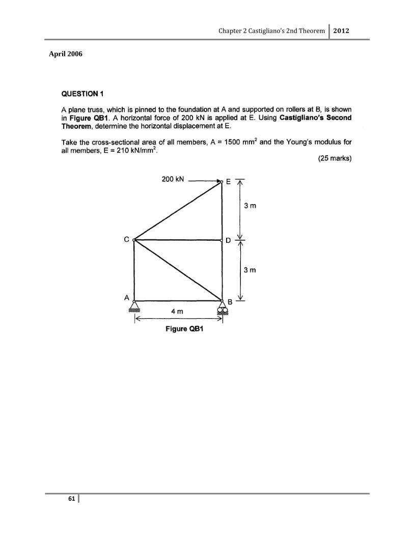
April 2006
Chapter 2 Castigliano’s 2nd Theorem 2012
62
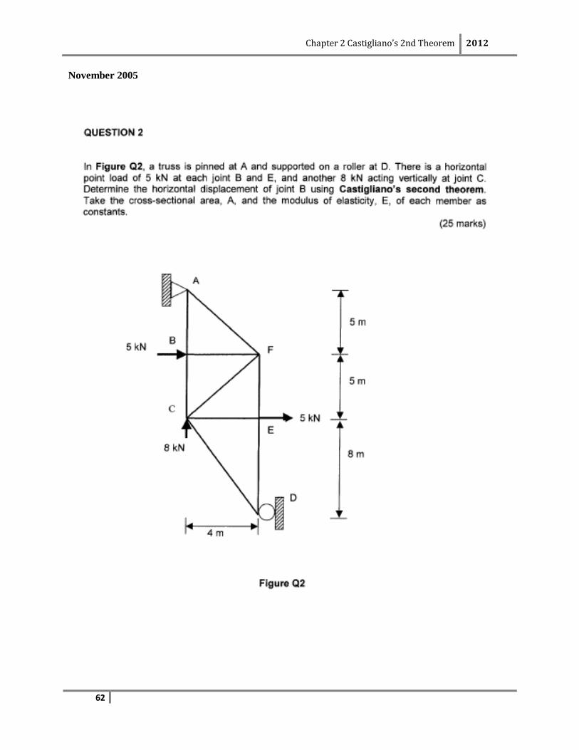
November 2005
Chapter 2 Castigliano’s 2nd Theorem 2012
63
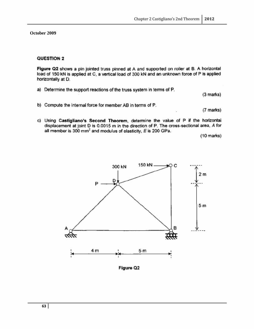
October 2009

Chapter 2 Castigliano’s 2nd Theorem 2012
64
October 2006