cast-in channels - cfs · pdf filecast-in channels 10 contents typical channel applications...
TRANSCRIPT
www.cfsfixings.comwww.cfsfixings.com 9-1
Cast-in Channels

www.cfsfixings.comwww.cfsfixings.com 9-2
CA
ST-IN C
HA
NN
ELS
10
ContentsTypical Channel Applications 9-3
Typical Cast-in Channel Anchor Variations 9-4
Cast-in Channel - Cold Rolled 9-5
Cast-in Channel - Hot Rolled 9-7
T-Bolts 9-8
Longitudinal Resistance 9-10
Toothed Channel Type CHT 9-11
CFS Flexi Channels Type F 9-12
CFS Captive Fixing Nuts 9-13
CFS UNI Channel 41/21 Cast-In Insert 9-14
Sled Channels for Metal Deck Floors 9-15
Met Stop for Fixing to the Edge of Metal Deck Floors 9-16
CFS Plain Back Channels 9-18
Special Channel Fabrications 9-19
Channels - Material, Standards 9-20

www.cfsfixings.comwww.cfsfixings.com 9-3
Typical Channel ApplicationsCurtain Wall
Curtain Wall: Bracket to Top of Slab
Masonry Support System: Fixing brick and stone support angles
Fixing of Mechanical Services
Lift guide rails
Curtain Wall: Bracket to Side of Slab
Structural Steel: Curtain Wall Bracket Steel to Structural Steel with Plain Backet Channel
Pipe Support Bracket to Underside of Slab
Fixing elevator guide rails and door surrounds

www.cfsfixings.comwww.cfsfixings.com 9-4
CA
ST-IN C
HA
NN
ELS
e = 25 mm approx
e e
e = 25 mm approx
e e
Typical Cast-in Channel Anchor VariationsCFS high quality inserts are designed to provide flexible fixing points for concrete structures. Channels are ideal for use near the edges of concrete where drilling is not possible. They are ideal for use in post-tensioned structures.
‘T’-bolts can be placed in the channels easily and moved to the desired position. Subsequent removal of components is very simple.
CFS-S stud anchor standard
CFS channels can be supplied with either of the above anchor configurations. The load capacity is identical. Standard anchor centres on long lengths of channel are 250 mm. Other centres can be supplied on request. Special anchor types can be provided to suit specific site requirements.
Cold Rolled or Hot Rolled
In most circumstances, cold rolled sections provide the appropriate solution. Where vibration is an issue or in safety-critical applications, hot rolled channels should be considered. If in doubt, seek advice.
CFS-W welded wave anchor
T-Bolts
T head bolts or locking plates are simply inserted anywhere along the channel and turned through 90° to block into position.
Filler
All channels intended for casting in contain CFS quick to remove filler.

www.cfsfixings.comwww.cfsfixings.com 9-5
Channel
Anchor
PEC-TA 28/15 Cold rolled Bolt anchor
PEC-TA 38/17 Cold rolled Bolt anchor
PEC-TA 40/25 Cold rolled Bolt anchor
PEC-TA 49/30 Cold rolled Bolt anchor
PEC-TA 54/33 Cold rolled Bolt anchor
PEC-TA 72/49
Cold rolled
Welded I anchor
Material
Hot-dip. galvan. x x x x x x
Stainless steel A4 x x x x x x
Stainless steel A2 On Demand On Demand On Demand On Demand On Demand On Demand
Bolt 28/15 38/17 40/22 50/30 50/30 72/48
hef,min /bch /hch 45/28/15 76/38/17 79/40/25 94/50/30 155/53.5/33 179/72/49
hef,min - Effective anchoring depth min. bch - Width of channel hch - Height of channel
Standard Short piece cast-in channels
Anchor centres (mm)
150 200 250 300 150 150 250 250
Standard channel lengths (mm)
150 200 250 300 350 550
Other short lengths are available to order, please consult CFS.
Cast-in Channel - Cold Rolled
Cold Rolled C-Channel
100 250
150mm (recommended minimum)
F F 2F2
Fr Fr Fr Fr Fr Fr
‘α’
15° min
‘β’
100 250
150mm (recommended minimum)
F F 2F2
Fr Fr Fr Fr Fr Fr
‘α’
15° min
‘β’
100 250
150mm (recommended minimum)
F F 2F2
Fr Fr Fr Fr Fr Fr
‘α’
15° min
‘β’
100 250
150mm (recommended minimum)
F F 2F2
Fr Fr Fr Fr Fr Fr
‘α’
15° min
‘β’
100 250
150mm (recommended minimum)
F F 2F2
Fr Fr Fr Fr Fr Fr
‘α’
15° min
‘β’
100 250
150mm (recommended minimum)
F F 2F2
Fr Fr Fr Fr Fr Fr
‘α’
15° min
‘β’

www.cfsfixings.comwww.cfsfixings.com 9-6
CA
ST-IN C
HA
NN
ELS
Cast-in Channel - Cold RolledDimensioning and design calculationsThe design of the products with a European Technical Approval is based on the standard CEN/TS 1992-4. We provide PEC Rail software to allow you to optimize product selection, which is available on our website www.cfs-fixings.com
The design loads for the CFS-PEC-TA Cast in channel are provided in this brochure. Please contact our technical office for assistance if necessary
Load capacities for cold rolled channelsCapacities per bolt where the T-bolts are spaced no closer than the anchors on the back of the channel
This table may be used in simple cases. The values are for tension only, shear only, or compare resultant forces of a tension and shear components with the shear capacities. In cases where there is a longitudinal force along the length of the channel, please see our nibbed bolt and toothed channel products.
These values are ultimate capacities and should be compared with the factored design loads.
PEC Rail software is available on our website www.cfs-fixings.com that would be useful for complex cases, with tensile and shear forces together, with close edge distances, different slab thickness or different concrete strength.
CFS will provide technical assistance for any problems you have, so if in doubt, ask for help.
Tension Capacity C25/30
Max Shear Capacity C30/37
Min Shear Capacity C30/37
Slab thickness ≥
Anchor Spacing
where c≥ Tension Only
where c≥ Shear Only
where c≥ Shear Only
(if thinner, consult software)
5min 5max
mm kN mm kN mm kN mm mm mm
CFS-PEC-TA 28/15
40 5 59 5 40 4.5 100 50 200
CFS-PEC-TA 38/17
50 10 90 10 50 5.5 125 100 200
CFS-PEC-TA 40/25
50 11.1 100 11.1 50 6.2 150 100 250
CFS-PEC-TA 49/30
75 17.2 141 17.2 75 9.4 150 100 250
CFS-PEC-TA 54/33
100 30.5 250 30.5 100 14.4 200 100 250
CFS-PEC-TA72/49
150 55.6 360 55.6 150 22.2 250 100 400

www.cfsfixings.comwww.cfsfixings.com 9-7
Channel
Anchor
PEC-TA 40/22
Hot rolled
Welded I anchor
PEC-TA 50/30
Hot rolled
Welded I anchor
PEC-TA 52/34
Hot rolled
Welded I anchor
Material
Hot-dip. galvan. x x x
Stainless steel A2 On Demand On Demand On Demand
Bolt to suitv 40/22 50/30 50/30
hef,min /bch /hch79/40/22 94/50/30 155/52/34
hef,min - Effective anchoring depth min. bch - Width of channel hch - Height of channel
Cast-in Channel - Hot Rolled
Hot Rolled C-Channel
Capacities per bolt where the T-bolts are spaced no closer than the anchors on the back of the channel
This table may be used in simple cases. The values are for tension only, shear only, or compare resultant forces of a tension and shear components with the shear capacities.These values are ultimate capacities and should be compared with the factored design loads.For more complicated design cases, please consult with CFS who will prepare a calculation for situation.
Tension Capacity C25/30
Shear Capacity C30/37
Shear Capacity C30/37
Slab thickness ≥
Anchor Spacing
where c≥ Tension Only
where c≥ Shear Only
where c≥ Shear Only
(if thinner, consult soft-ware)
5min 5max
mm kN mm kN mm kN mm mm mm
PEC-TA 40/22 50 11.1 100 11.1 50 6.4 150 100 250
PEC-TA 50/30 75 17.2 141 17.2 75 4 150 100 250
PEC-TA 52/34 100 30.6 250 30.5 100 6.1 200 100 250

www.cfsfixings.comwww.cfsfixings.com 9-8
CA
ST-IN C
HA
NN
ELS
T-BoltsCFS T-bolts are drop forged specifically designed to be used with the appropriate channel section. All mild steel T-bolts are supplied electroplated finish as standard grade 4.6.
They are also available grade 4.6 hot dip spun galvanised to BS-1971 to provide a minimum of 43 microns thickness. Stainless steel T-bolts are A2 grade 50.
Grade A4 and class 70 are also available to order. Please note that when deciding the correct channel and ‘T’-bolt combination the load capacity of both channel and ‘T’-bolt need to be taken into consideration.
Type T Bolt 28/15 T Bolt 38/17 T Bolt 40/22 T Bolt 50/30 T Bolt 72/48
All bolts are delivered in one box with nuts and washers. Nuts and washers are packed in separate plastic bags.
Electro zinc plated* x x x x x
Stainless steel A4 x x x x x
Grade 4.6 as standard x x x x x
8.8 on request x x x x x
Diameter M8-M12 M10-M16 M10-M16 M12-M20 M20-M30
Length (mm) 15-100 20-200 20-300 30-300 50-200
*Hot-dip galvanised available on request.
* Please also check channel capacities for the conditions present.
Size Range for Channels
Bolt size
Grade 4.6 Grade 8.8
Torque
Nm
Max. Load kN* Bending
Moment kNm
Torque Nm
Max. Load kN* Bending
Moment
kNmTension Shear Tension Shear
M 6 3 4.3 2.9 3 3 11.6 6.4 9
M 8 8 7.9 5.3 8 8 21.1 11.7 22
M 10 13 12.5 8.4 16 15 33.4 18.6 43
M 12 25 18.2 12.1 28 25 48.6 27 75
M 16 40 33.9 22.6 72 40 90.4 50.2 192
M 20 120 52.9 35.3 140 120 141.1 78.4 374
M 24 200 76.3 50.7 242 200 203.3 113 647
M 27 300 99.1 66 360 300 264.1 146.9 959
M 30 380 121.1 80.6 486 380 322.8 179.5 1295
SWL and Technical Characteristics

www.cfsfixings.comwww.cfsfixings.com 9-9
Once you have determined the minimum required bolt length for your application, please consult with CFS to establish the suitable stock length. We carry a wide range of lengths in stock.
Profile Type f (mm) Bolt m+s+u (mm)
CFS-PEC-TA 28/15 Cold 2.3 M6 8.8
CFS-PEC-TA 38/17 Cold 3 M8 11.3
CFS-PEC-TA 40/25 Cold 6 M10 13.9
CFS-PEC-TA 49/30 Cold 7.5 M12 17.3
CFS-PEC-TA 54/33 Cold 8 M16 21.8
CFS-PEC-TA 72/49 Cold 10 M20 27.0
CFS-PEC-TA 40/22 Hot 6 M24 32.5
CFS-PEC-TA 50/30 Hot 8 M27 36.5
CFS-PEC-TA 52/34 Hot 11.5 M30 40
Cold = Cold rolled Hot = Hot rolled
l = Required bolt length
f = Height of the profile lip
m = Height of the nut
s = Thickness of the washer
lk = Clamping thickness
u = Length of bolt protruding
DETERMINING REQUIRED BOLT LENGTH

www.cfsfixings.comwww.cfsfixings.com 9-10
CA
ST-IN C
HA
NN
ELS
Nibbed T-BoltsThese bolts must be used with hot rolled channels, hot dipped galvanized. All bolts grade 8.8
Channel Nibbed T-Bolt Toque Nm
Longitudinal Design Capacity kN
CFS-PEC-TA 40/22 HSZ 40-22 M16 120 4.1
CFS-PEC-TA 50/30 HSZ 50-30 M16 120 10.0
CFS-PEC-TA 50/30 HSZ 50-30 M20 360 11.8
CFS-PEC-TA 52/34 HSZ 52-34 M20 360 11.8
Longitudinal ResistanceWhere forces exist along the length of the channel, there are two alternative solutions, ribbed T-Bolts alongside our hot-rolled channels, or toothed channels. If in doubt, please send your conditions to CFS for advice.
A steel-to-steel contact is required between channel and attachment. A calibrated torque wrench must be used.

www.cfsfixings.comwww.cfsfixings.com 9-11
Toothed Channel Type CHTBolt diameter
Channel profile (CHT)
Allowable loads in reinforced concrete (kN)†
Long length Short channel or single bolt with bolt pair 3-anchor
Longitudinal loads
Long length Bolt pair or single bolt 2-anchor* 3-anchor*
Minimum spacing in reinforced concrete (mm)
Channel spacing Normal pair Parallel edge End edge C1 C2 C3
T-bolts Grade 8.8
M16 38/23 41/22
12.0 20.0 8.0 14.0
12.0 20.0 24.0 5.5 8.0 110
125 85 75 100 75 60
M12 38/23 41/22
12.0 20.0 8.0 14.0
12.0 20.0 24.0 5.5 8.0 11.0
125 85 75 100 75 50
Stainless steel bolts
M16 41/22 8.0 14.0 5.5 8.0 11.0 100 75 60
M12 41/22 8.0 14.0 4.0 8.0 8.0 100 75 50
Notes: *Subject to check on resultant load. †Pull-out, transverse shear or resultant loads. Allowable loads quoted are after application of a Safety Factor of approximately 2.5 on test in reinforced concrete. For extreme bolt positions and minimum cut edge distances, please consult CFS Ltd. Two bolts on the same channel taking longitudinal loads can be as little as 50mm apart, please consult CFS Ltd.
Allowablelongitudinalload
7 mm
Bolt length
Teeth pitch3 mm
60 min
)mm(etercnocdecrofniernignicapsmuminiM)Nk(etercnocdecrofniernisdaolelbawollAlennahCtloBgnicapslennahC)sdaollanidutignol()sdaoltnatluserroraehsesrevsnart,tuo-llup(eliforpretemaid
(CHT) Long length Short channel with bolt pair Long length Bolt pair Normal pair Parallel edge End edge*rohcna-3*rohcna-2tlobelgnisrorohcna-3tlobelgnisro C1 C2 C3
T- bolts Grade 8.8
M16 57585210.420.020.210.020.2132/83
06570010.110.85.50.410.822/14
M12 57585210.420.020.210.020.2132/83
05570010.110.85.50.410.822/14
Stainless steel bolts
M16 06570010.110.85.50.410.822/14
M12 05570010.80.80.40.410.822/14
Notes:* Subject to check on resultant load.Allowable loads quoted are after application of a Safety Factor of approximately 2.5 on test in reinforced concrete.For extreme bolt positions andminimum cut edge distances, please consult CFS Ltd.Two bolts on the same channel taking longitudinal loads can be as little as 50 mm apart; please consult CFS Ltd .
250 250
250 150 150
150
T-head bolts for channels CHT 38/23 and 41/22
)mm(elbaliavashtgneltlobleetssselniatS)mm(elbaliavashtgneltloT-btloBlennahC)CZS(2A)CZS(4A)CZS(8.8edarGretemaideliforp
38/23 M16 06003,002,051,521,001,08,06,05,04,03
M12 30, 40, 50, 60, 80, 100,125,150,200,300
41/22 M16 57,06,05,0405,53001,05
M12 0508,05,5305,53
C1 C2
C3

www.cfsfixings.comwww.cfsfixings.com 9-12
CA
ST-IN C
HA
NN
ELS
CFS Flexi Channels Type FCFS Flexi Channels are ideally suited for the quick, reliable and cost efficient fixing of different construction elements to metal deck floors.
The insert can be adjusted in height to suit the varying floor profiles and fabricated ski assemblies are simple to fit to the base of the adjustable feet.
• Loads based on minimum C35 concrete strength • For 350mm channels minimum bolt centres = 150mm • For minimum height flexi anchors reduce the load by (x 0.92)
CFS Cast-In 49/30 with Flexible Anchor
Product Description Hot dipped galvanized or stainless steel
Length [mm]
Number of Anchors
Min. Total Height [mm]
Max. Total [mm]
CFS - TA/F - 40/25, 49/30 200 or 350 200 (2) / 350 (3) 60 90
CFS - TA/F - 40/25, 49/30, 54/33 200 or 350 200 (2) / 350 (3) 85 110
CFS - TA/F - 40/25, 49/30, 54/33 200 or 350 200 (2) / 350 (3) 108 158
Other lengths / profile types or materials are available on requestFor min. total height = 60mm the loads FRd have to be reduced by factor 0.92
N
V
V
V N
N
3.25
49
30 Tota
l min
and
max
hei
ght
200m 350m
Section Tension [kN] SWL [NRD]
Shear [kN] SWL [N]
Resultant [kN]
SWL [R]
Min. Edge Distance [mm]
T-Bolts SWL
40/25 10 10 10 120 12mm (9.3kN) 16mm (17.3kN)
49/30 15 15 15 150 16mm (17.3kN) 20mm (27.0kN)
54/33 25 25 25 250 16mm (17.3kN) 20mm (27.0kN)
All load values in accordance with design criteria CEN /TS 1992-4-3

www.cfsfixings.comwww.cfsfixings.com 9-13
Captive Nut Indicative Load Capacities
40/25 Channel c/w M12 Captive Nut 8kN Tensile: 10kN Shear
49/30 Channel c/w M16 Captive Nut 12.5kN Tensile: 15kN Shear
54/33 Channel c/w M20 Captive Nut 25kN Tensile: 25kN Shear
40/25 Channel c/w M12 Captive Nut
49/30 Channel c/w M16 Captive Nut
54/33 Channel c/w M20 Captive Nut
CFS Captive Fixing NutsThe Economic Fix to Channel InsertsThe main benefits are:
• Channels are supplied ready for casting in complete with the channel nuts.
• Very quick to install – no down time looking for seperate T-Bolts.
• Very economical particularly for larger diameters and longer projections.
Captive Nut Data for Cast-In Channel Inserts

www.cfsfixings.comwww.cfsfixings.com 9-14
CA
ST-IN C
HA
NN
ELS
CFS UNI Channel 41/21 Cast-In InsertSize: 41 x 21 x 2.5mm• Concrete inserts are available in standard lengths of
3 metres which are supplied complete with polystyrene infill and End Caps in place.
• Non-standard lengths can be supplied in increments of 200mm. Dedicated lengths to suit your requirements can also be produced.
• Finish pre-galvanised or hot dip galvanised. If site installation requires the concrete insert to be cut and end caps must be reinserted at each end.
100mm
100mm
100mm
1522
39
7mm DiameterFixing Hole 21mm
41mmUNI Channel 41/21 Safe working load
Point load (250mm centres) 5.5 kN
Continuous Load (per 1000mm) 22 kN
Concrete Strength 35 N/mm
Recommended loadings

www.cfsfixings.comwww.cfsfixings.com 9-15
9–8
CAST-IN CHANNEL
MET STOP FOR FIXING TO THE EDGE OF METAL DECK FLOORS
CFS Met-stop provides the complete solution forfixing to metal deck floors. Comprising a cast-inchannel contained within a metal edge trim.
toorder
CFS Met-stop is manufactured to suit yourparticular project conditions. Met-stop edge trimis produced from pre-galvanized sheet witheither hot-dip galvanized or stainless steelchannel inserts.
to order
Min50
Typical installation showing Met stop shot firedor tek-screwed down to the steel frame.Restraint straps are provided to give additionalrestraint to the upper edge.
Fix restraint straps, tying verticalleg back to the metal decking
9–7
CAST-IN CHANNEL
SLED CHANNELS FOR METAL DECK FLOORS
CFS sled channels are designed to to be used inthe top surface of metal deck floors. Sled channelassemblies allow channel inserts to be easilypositioned so that they are flush with the surfaceof the concrete and maintain a correct edgedistance from the decking edge trim.
Sled channel assemblies are fabricated to suityour particular project requirements. Wemanufacture to suit your slab depth and deckingtype and edge condition details. CFS will bepleased to advise of the most economicalassembly for you.
TYPICAL SLED DETAIL
SLED ALLOWABLE LOAD DATA(for typical example when used to fix curtain walling)
Min. edge Resultant Loads (R) Reinforcement
Channel distance e Single point Bolt pair* requirements
38/17 100 mm 16 kN 12 kN Standard mesh
40/25 125 mm 18 kN 16 kN and
49/30 150 mm 10 kN 20 kN 10 mm dia. bar
Notes: Quoted loads assume unit cast into lightweight con- 450 mm long
crete minimum 130 mm thick, 25 N/mm2 strength and are with
after the application of a safety factor of approximately 3:1. 4 No.
* Loads quoted assume the component is fixed to sled 10 mm dia.
assembly using two bolts minimum 100 mm apart. Bobs(300/80)
Single, double or triple channelassemblies can be produced.
Manufactured to suit the slab depth,or to sit on top of the ribs.Please advise your exact decking detail.
Edge spacers give precise setting out.
e
³ 50
Resultantload (R)
Additional reinforcement
Mesh
³ 25
9-7
Ski allowable load data (for typical example when used to fix curtain walling)
Channel with support foot for metal deck flooring
Sled Channels for Metal Deck FloorsCFS ski channels are designed to to be used in the top surface of metal deck floors. Ski channel assemblies allow channel inserts to be easily positioned so that they are flush with the surface of the concrete and maintain a correct edge distance from the decking edge trim.
Ski channel assemblies are fabricated to suit your particular project requirements. We manufacture to suit your slab depth and decking type and edge condition details. CFS will be pleased to advise of the most economical assembly for you.
toorder
to order
Min50
Fix restraint straps, tying verticalleg backto the metal decking
Single, double or triple channelassemblies can be produced.
Manufactured to suit the slab depth,or to sit on top of the ribs.Please advise your exact decking detail.
Edge spacers give precise setting out.
e³ 50
Resultantload (R)
Additional reinforcement
Mesh
³ 25

www.cfsfixings.comwww.cfsfixings.com 9-16
CA
ST-IN C
HA
NN
ELS
Met Stop for Fixing to the Edge of Metal Deck FloorsCFS Met stop provides the complete solution for fixing to metal deck floors. Comprising a cast-in channel contained within a metal edge trim.
toorder
to order
Min50
Fix restraint straps, tying verticalleg backto the metal decking
Single, double or triple channelassemblies can be produced.
Manufactured to suit the slab depth,or to sit on top of the ribs.Please advise your exact decking detail.
Edge spacers give precise setting out.
e³ 50
Resultantload (R)
Additional reinforcement
Mesh
³ 25
CFS Met stop is manufactured to suit your particular project conditions. Met-stop edge trim is produced from pre-galvanized sheet with either hot-dip galvanized or stainless steel channel inserts.
Typical installation showing Met stop shot fired or tek-screwed down to the steel frame. Restraint straps are provided to give additional restraint to the upper edge.
www.cfsfixings.comwww.cfsfixings.com 9-17
c
a
b
250mm mc
edF
300 standartmesh
to order
min
.50
toor
der
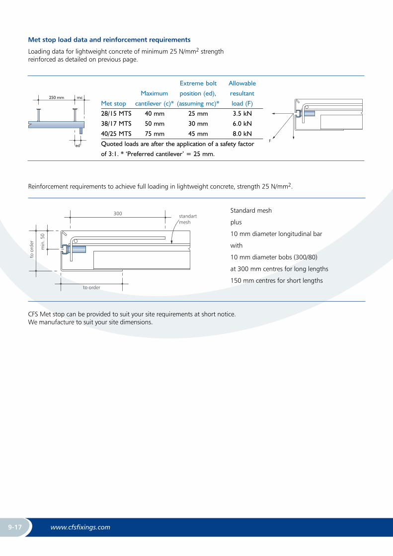
Met stop load data and reinforcement requirements
Loading data for lightweight concrete of minimum 25 N/mm2 strength reinforced as detailed on previous page.
9–10
CAST-IN CHANNEL
LIFT BLOCKS
INTRODUCTIONCFS lift blocks are the ideal solution for installinginserts into block or brick lift shaft walls. Timeconsuming casting of pad-stones on site withinwalls is completely avoided. CFS produces cast
CFS LIFT BLOCKSBUILT WITHIN A LIFT SHAFT WALL.
Dimensions a, b and c to orderLift blocks over 50 kg contain 2 No. liftingsockets.
c
a
b
blocks containing CFS inserts. CFS lift blocksare manufactured bespoke to suit your projectconditions.
9–9
CAST-IN CHANNEL
Extreme bolt Allowable
Maximum position (ed), resultant
Met stop cantilever (c)* (assuming mc)* load (F)
28/15 MTS 40 mm 25 mm 3.5 kN
38/17 MTS 50 mm 30 mm 6.0 kN
40/25 MTS 75 mm 45 mm 8.0 kN
Quoted loads are after the application of a safety factor
of 3:1. * ‘Preferred cantilever’ = 25 mm.
MET STOP LOAD DATA AND REINFORCEMENT REQUIREMENTS
Loading data for lightweight concrete of minimum 25 N/mm2 strength reinforcedas detailed on previous page.
Reinforcement requirements to achieve full loading in lightweight concrete, strength 25 N/mm2.
Standard mesh
plus
10 mm diameter longitudinal bar
with
10 mm diameter bobs (300/80)
at 300 mm centres for long lengths
150 mm centres for short lengths
CFS Met-stop can be provided to suit your siterequirements at short notice. We manufacture tosuit your site dimensions.
250 mm mc
edF
300 standartmesh
to order
min
.50
toor
der
9-9
Reinforcement requirements to achieve full loading in lightweight concrete, strength 25 N/mm2.
Standard mesh
plus
10 mm diameter longitudinal bar
with
10 mm diameter bobs (300/80)
at 300 mm centres for long lengths
150 mm centres for short lengths
CFS Met stop can be provided to suit your site requirements at short notice. We manufacture to suit your site dimensions.

www.cfsfixings.comwww.cfsfixings.com 9-18
CA
ST-IN C
HA
NN
ELS
Max.point load
Bending load capacity at span L (single span element) Corresponding BoltF flex [kN] 2x F flex [kN] q flex [kN/m]
Fz [kN]
L max
[cm]
L [m] L [m] L [m] Type Thread
0.50 1.00 1.50 0.50 1.00 1.50 0.50 1.00 1.50 M
28/15 3.9 8 0.8 0.3 0.12 0.6 0.16 0.07 3.3 0.4 0.13 28/15 6-12
38/17 4.8 11 1.5 0.6 0.3 1.1 0.3 0.15 6.1 0.9 0.3 38/17 10-16
41/41 5.6 49 5.4 2.7 1.8 4.0 2.0 1.3 21.5 5.4 2.3 41/41 8-16
40/25 3.8 33 2.6 1.3 0.6 1.9 0.8 0.4 10.3 2.2 0.7 40/22 10-16
49/30 4.9 46 4.3 2.2 1.2 3.3 1.6 0.7 17.4 4.3 1.3 50/30 10-20
40/22 5.7 21 2.6 1.3 0.6 2.0 0.8 0.3 10.5 2.1 0.6 40/22 10-16
50/30 11.0 19 5.3 2.7 1.6 4.0 2.0 0.9 21.4 5.3 1.7 50/30 10-20
52/34 17.0 21 8.8 4.4 2.8 6.6 3.3 1.6 35.1 8.8 3.0 50/30 10-20
72/48 31.0 32 22.3 11.2 7.4 16.7 8.4 5.6 89.3 22.3 9.9 72/48 20-30
All load bearing are calculated as elastic-plastic values according to DIN 18800; these are approximate values and can be used for EC3.Partial safey coefficient gamma f=1.4, deflection =max l/150. Calculate the design values as FR,d=1.4xFFor other sizes, please consult CFS.
CFS Plain Back ChannelsPlain back channels are useful in non-concrete applications for example, welded to steel stations.

www.cfsfixings.comwww.cfsfixings.com 9-19
SKI Channel for the Metal Deck Floor
Special Channel Fabrications
Radiussed
Welded in pairs to aid setting out
Fabricated corner piece

www.cfsfixings.comwww.cfsfixings.com 9-20
CA
ST-IN C
HA
NN
ELS
T-Bolt Grade 4.6, Grade 8.8
Hot Dip Galvanized DIN EN ISO 10684,
DIN EN ISO 898-1
DIN EN ISO 4034
zinc coating ≥ 40 µm
DIN 50961, DIN EN 1403,
DIN EN ISO 4042
DIN EN ISO 898-1
zinc coating ≥12 µm
Grade A2-50, A2-70
Grade A4-50, A4-70
Stainless Steel HCR
Material No. 1.4529, HCR50
DIN EN 3506-1
DIN EN 10 088
A4
Material No. 1.4401/ 1.4404/ 1.4571
DIN EN ISO 3506-1
DIN EN 10 088
Channel Hot Rolled, Cold Rolled
Mild Steel Material S235JR (RSt 37-2)
Material No. 1.0038, 1.0044
DIN EN 10025
Hot Dip Galvanized
Material S235JR (RSt 37-2)
Material No. 1.0038, 1.0044
DIN EN 10025
hot dip galvanised - DIN EN ISO 1461,
zinc coating ≥ 50 µm
Stainless Steel HCR
Material No. 1.4529/1.4547
DIN EN 10088
A4
Material No. 1.4401/ 1.4404/ 1.4571
DIN EN 10088
Channels - Material, Standards