casi/tmi final report for phase iicoe.ou.edu/manufacturing/fixture design/reports/final report...
TRANSCRIPT
CASI/TMI FINAL REPORT FOR PHASE II to accompany the on-line Fixture Design Manual
FIXTURE DESIGN CRITERIA
PHASE II
Shivakumar Raman, Ph.D., Principal Investigator*
Aashish Wadke, Graduate Student Assistant
John Simpsen, Undergraduate Student Assistant
Heather Matthews, Undergraduate Student Assistant
July 29, 2004
Norman, OK 73019
Address all correspondence to
Dr. Shivakumar Raman, David Ross Boyd Professor,
School of Industrial Engineering, 202 W.Boyd, Ste. 124, CEC,
University of Oklahoma, Norman, OK 73019
Phase II Report CASI/TMI 2003 Fixture Design Criteria: Phase II
ABSTRACT
The overall objective of this project is to research technologies to improve and speed
fixture designs within Tinker AFB. The proposed product at the end of three phases is a
comprehensive Roadmap for Fixture design and sample of the process involving some
complex fixtures representing the major production areas within the center. Through the
Phase I Project an electronic fixture design manual was initiated. An interactive fixture
design advisor is developed in Phase II that provides a computerized animation of 11
fixtures actually designed and implemented at Tinker. This report summarizes the
progress-to-date of the project Fixture Design Criteria. Projected benefits of the project
include improved repair processes, reduced costs, and higher reaction speeds.
2

Phase II Report CASI/TMI 2003 Fixture Design Criteria: Phase II
INTRODUCTION
The overall objective of this project is to research technologies to improve and speed
fixture designs within Tinker AFB. The proposed product is a Roadmap for Fixture
design and a prototype of the process involving 5-10 complex fixtures representing the
major production areas within the center. Through the Phase I Project an electronic
fixture design manual has been initiated. Currently, this manual has fixture design detail,
the components of jigs and fixtures and a step-by-step design procedure. A CAD
animation has been developed and hyperlinked to show 3-D manipulation. This manual
has been so developed that a beginner may design a fixture from scratch. Another module
shows possible hydraulic chucks and fixture components with pricing. These manuals are
currently specific to machining fixtures and consider hypothetical scenarios. During
Phase II, 10 actual fixtures designed and implemented at the base by Tinker Shop
Engineers are studied, analyzed and computerized (animated) within manipulable,
interactive software VRML.
Basic fixture design for manufacturing applications envelopes two main aspects:
location and clamping. Between these two functions, the 6 (3 translation and 3 rotation)
degrees of freedom are constrained, while effectively positioning and orienting the part
during processing. The location of box-type parts is usually achieved using the 3-2-1
principle. This principle locates the primary plane by three non-collinear points, typically
widely spaced; the second plane is located by two points and the third plane by one point.
Cylindrical part axes are usually located using V-blocks while concentric locators are
used to locate priorly drilled holes. The cutting wrenches (forces) are supported by
effectively holding the workpiece, to minimize distortion or deformation of the object.
Chip clearance, ease of part loading and removal, use in multiple applications (versatility)
is often additional considerations in designing fixtures. Jigs also provide tool guidance in
addition to the location and clamping provided by fixtures. Usually sheet metal
fabrication and assembly often requires other types of fixtures than machining fixtures.
In any case, fixture design is most cost-justified for batch or mass production runs.
Considering this, the fixture designs for single-piece parts are better accomplished by
modular fixtures. Fixture design is typically a setup cost function, making it very
3

Phase II Report CASI/TMI 2003 Fixture Design Criteria: Phase II
valuable in flow time and indirect cost calculations. Due to the rapid response required in
many applications, the fixture design principles must be integrated and properly detailed
so as to facilitate the fast design development of a fixture. Flexible, palletized and
modular fixtures are quite common in today’s industry to maintain rapid tooling in the
agile environment.
This project researches the parts manufactured at the base and some fixtures currently
developed and employed for specific applications. Correlation between theoretical
fixture design principles and actual practical development at Tinker can be drawn through
such an exercise. At the end of the three phases of this project, a formal generalization of
the concepts and methodologies of fixture design for Tinker will be developed. Specific
constraints for each shop will again be identified. Hence, a step-by-step procedure for jig
and fixture design will be developed. In addition to a hard-copy fixture design manual, a
procedural CD-ROM/Web-page for fixture design principles for manufacturing of
different part geometries will be developed. The links with conventional CAD and CAE
systems will be explored to automatically integrate part design concepts and engineering
(stress, deflection, etc.) analysis. In summary, a roadmap to fixture design and/or
existing fixture modification will be developed.
BACKGROUND
This report presents a basic detail of the information compiled for the electronic
Fixture Design Advisor. Information useful to the design of work-holding devices for
different operations was compiled and presented in Phase I. The principles of design,
essential elements of fixturing, dos and don’ts, and different devices available for quick
fixturing were discussed in detail. Phase I also presented information on hydraulic
chucks, jigs, and fixtures, as requested by the sponsor.
The information was compiled in the form of a web page. The fixturing principles
were illustrated using pictures and animations. At the conclusion of Phase I feedback was
obtained from the sponsor and other Tinker officials. A need was felt to add a certain
amount of user interaction in the learning process and to allow the user to visualize
4

Phase II Report CASI/TMI 2003 Fixture Design Criteria: Phase II
fixturing principles more clearly. Three-dimensional representations of fixtures and
fixturing principles were deemed useful in understanding assembly and design of
fixtures. Three-dimensional (3D) virtual environment is well suited for this purpose,
where a user has a free hand to move around in the three dimensional world, and look
into different aspects of fixturing. Further, if the user is able to actually assemble any
fixture in this virtual environment, it would only help the learning process.
The objective of the second phase is to develop a computerized virtual
environment, where a person can visualize the fixturing principles using three
dimensional models. The system should also allow the user to interact with the fixtures
and try and assemble different parts of the fixture. It is also important to have the system
independent of any operating platforms and commercial CAD software such as
Pro/Engineer®, Ideas TM, and Solid Works TM so that time is not spent learning the
complex CAD software. Over the past few years internet technologies have gained a
prominent role in commerce, entertainment, information and education. Internet
technologies are being exploited by many industries for improving their operations.
Considering the requirements of the project and vast capabilities of internet technology, it
was decided to build the ‘Fixture Design Advisor’ using Internet technology. It was also
decided that existing fixtures will be demonstrated through modular assembly and
manipulation within a virtual modeling system.
Selection of 3D Technology over internet
Internet technologies such as Macromedia® Flash and Macromedia® Director are
used to enhance online presentations and developing online applications. Though
Director® 3D software is used widely for representing three Dimensions on the Internet;
Virtual Reality Modeling Language (VRML) can be used more effectively to manipulate
3D models on the Internet. JAVA can be used extensively with VRML to manipulate the
3D worlds. Unlike Director®, VRML provides more flexibility. VRML just requires a
VRML browser plug-in to be installed on to the computer so as to view ‘VRML Worlds’.
VRML was chosen as a platform to develop the fixture design advisor because of its
5
Phase II Report CASI/TMI 2003 Fixture Design Criteria: Phase II
flexible programming language. VRML can easily blend with HTML and JAVA making
the overall system very flexible.
Introduction to Virtual Reality Modeling Language (VRML)
Virtual Reality Modeling Language (VRML) was developed basically for viewing
3-D graphics on the web. VRML is neither a virtual reality language nor a modeling
language, but is a 3D interchange format. It defines most of the semantics found in
today’s 3D applications such as hierarchical transformations, light sources, viewpoints,
geometry, animations, material properties and texture mapping. It is basically a 3D
analog to HTML (Hyper Text Markup Language). The basic idea behind developing
VRML is to achieve “Perceptualized” Internetworks, which simply means expressing
Internet as per human perceptions. VRML file is just a file format used for sending
descriptions of virtual worlds to and fro over the Internet. The most exciting feature of
VRML is that it enables one to create highly dynamic worlds. VRML has the ability to;
• Animate objects in the virtual world.
• Allow users to interact with the world and move objects in it.
• Play sounds and movies within the defined world.
• Control and enhance worlds with embedded small programs to increase
interaction between user and VRML world.
Brief History of VRML
It all started in spring of 1994 at the first annual World Wide Web Conference in
Geneva, Switzerland held by Tim Berners-Lee and Dave Raggett to discuss virtual reality
interfaces to the World Wide Web (WWW). Initialized as Virtual Reality Markup
Language, further the name was changed to Virtual Reality Modeling language in order
to reflect the graphic nature of VRML. VRML 1.0 specification was produced by Silicon
Graphics Inc. soon after the conference. However VRML 1.0 worlds were static and
contained only stationary objects with no user interaction. Hence VRML 2.0
Specification including key features like animation, interaction, and behavior was
developed by Silicon Graphics, Inc in collaboration with Sony Corporation and Mitra
(http://www.mitra.biz/). First version of VRML 2.0 was released in August 1996 at
6

Phase II Report CASI/TMI 2003 Fixture Design Criteria: Phase II
‘SIGGRAPH 96’ in New Orleans. VRML 2.0 Specification was accepted as an ISO
standard in April 1997.
VRML
A VRML file is basically a textual description of the VRML world. The VRML
file is edited in any text editor such as notepad or WordPad but is characterized by the
extension ‘.wrl’. The VRML file contains all the information to build shapes, position
shapes, and animate shapes and can also contain embedded java codes to add user
interaction and computation of data. Whenever a web browser (e.g. Internet Explorer,
Microsoft Corporation) with a special utility, called VRML plug-in, reads a VRML file
with ‘.wrl’ extension, it builds a world exactly as described by the file. The different
VRML plug-ins available for viewing VRML worlds are;
‘Cosmo® Player’ by Computer Associates, Inc.
‘Cortona® VRML Client’ by Parallel Graphics
Cosmo® Player is used for the project because of its user-friendly menus and good
functionality.
VRML File Structure
The VRML file consists of following four typical components:
• The VRML header
• Prototypes
• Shapes, Interpolators, Sensors, Scripts
• Routes
The VRML files can be considered as a compilation of nodes, fields, and field values.
Consider the following Fixture assembly
7
Phase II Report CASI/TMI 2003 Fixture Design Criteria: Phase II
The fixture shown above consists of three components: the part, the fixture and tightening
screw. Each of these parts in the assembly can be considered as node and the attributes of
the part as color contrast and shape coordinates can be considered field values. Using
animation node, sensor node, motion node, and other nodes in VRML specification user
interaction with the world is achieved. The different programmable nodes used for fixture
assembly are;
Viewpoint Node:
This node assigns different viewpoints in the VRML world. Different views for
the fixture have been created using this viewpoint node.
PlaneSensor Node:
This node allows the world to react to how a user moves the mouse cursor in the
VRML world. Assembly of fixturing elements has been created using this node.
Transform Node:
This node translates a particular shape in the world. All the parts in the world
have been repositioned using this node. The parts can be translated or rotated using this
node.
Animations:
The animation in the VRML world is a combined effect of TimeSensor,
PositionInterpolator, OreintationInterpolator, Transform nodes, and many more such
nodes. The animations also include use of script nodes, which either have VRML or Java
scripts.
Creation of Fixture Assembly in VRML
Considering the complexity of the fixture geometry, the fixtures were built in
CAD software Pro/Engineer®. The models were then exported in VRML file format. The
use of Pro/Engineer® was limited to building individual components of the complete
fixture assembly. The different attributes of the parts such as color, position in fixture
8
Phase II Report CASI/TMI 2003 Fixture Design Criteria: Phase II
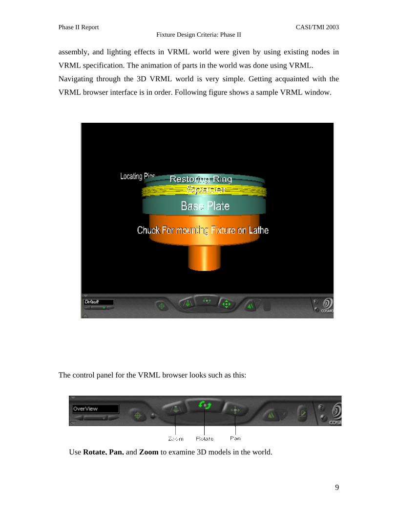
assembly, and lighting effects in VRML world were given by using existing nodes in
VRML specification. The animation of parts in the world was done using VRML.
Navigating through the 3D VRML world is very simple. Getting acquainted with the
VRML browser interface is in order. Following figure shows a sample VRML window.
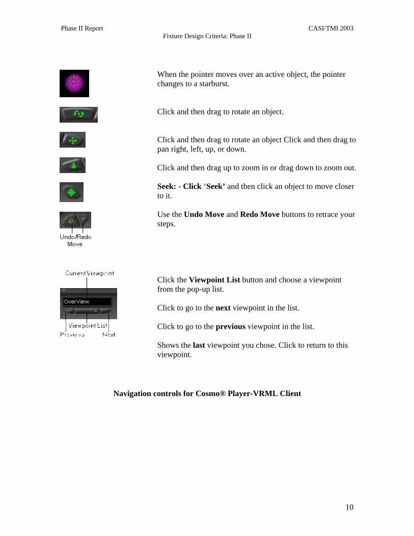
The co
ntrol panel for the VRML browser looks such as this:
Use Rotate, Pan, and Zoom to examine 3D models in the world.
9
Phase II Report CASI/TMI 2003 Fixture Design Criteria: Phase II
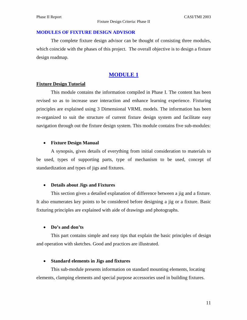
When the pointer moves over an active object, the pointer changes to a starburst. Click and then drag to rotate an object. Click and then drag to rotate an object Click and then drag to pan right, left, up, or down. Click and then drag up to zoom in or drag down to zoom out. Seek: - Click ‘Seek’ and then click an object to move closer to it. Use the Undo Move and Redo Move buttons to retrace your steps. Click the Viewpoint List button and choose a viewpoint from the pop-up list. Click to go to the next viewpoint in the list. Click to go to the previous viewpoint in the list. Shows the last viewpoint you chose. Click to return to this viewpoint.
Navigation controls for Cosmo® Player-VRML Client
10
Phase II Report CASI/TMI 2003 Fixture Design Criteria: Phase II
MODULES OF FIXTURE DESIGN ADVISOR
The complete fixture design advisor can be thought of consisting three modules,
which coincide with the phases of this project. The overall objective is to design a fixture
design roadmap.
MODULE 1 Fixture Design Tutorial
This module contains the information compiled in Phase I. The content has been
revised so as to increase user interaction and enhance learning experience. Fixturing
principles are explained using 3 Dimensional VRML models. The information has been
re-organized to suit the structure of current fixture design system and facilitate easy
navigation through out the fixture design system. This module contains five sub-modules:
• Fixture Design Manual
A synopsis, gives details of everything from initial consideration to materials to
be used, types of supporting parts, type of mechanism to be used, concept of
standardization and types of jigs and fixtures.
• Details about Jigs and Fixtures
This section gives a detailed explanation of difference between a jig and a fixture.
It also enumerates key points to be considered before designing a jig or a fixture. Basic
fixturing principles are explained with aide of drawings and photographs.
• Do’s and don’ts
This part contains simple and easy tips that explain the basic principles of design
and operation with sketches. Good and practices are illustrated.
• Standard elements in Jigs and fixtures
This sub-module presents information on standard mounting elements, locating
elements, clamping elements and special purpose accessories used in building fixtures.
11

Phase II Report CASI/TMI 2003 Fixture Design Criteria: Phase II
• Details about Hydraulic Chucks
The different types of chucks with their physical dimensions and characteristics
are explained. Different types of chucks are compared. This is a more specific detail,
done largely to assist the sponsor in some implementation decisions.
• Animations on Practical devices
Animations are shown for different types of jigs and fixtures used for various
operations such as drilling, milling, lapping, and turning, showing the locator positions
and clamping positions so that basic principles could easily be understood.
Fixture Design Manual
This section helps design fixtures from concept to prototype. The initial stage is
the planning stage and the finishing stages represent the practical work handling steps.
The manual is intended to serve as a reference book that has all the information about
fixture design. This information related to the design of jigs and fixtures is collected and
compiled in this section.
Practical application of the fixture should be considered before designing the
fixture. The fixture designed has to comply with the current manufacturing standards in
the industry. The fixtures built should be compatible with the available machinery and
the manufacturing process involved should be less time consuming and cost effective.
The material to be used, rigidity of the fixture, upkeep of fixture, salvageability, and
safety of the operator in using the fixture have to be all considered before designing the
fixture. The design manual touches on all these aspects of fixture design.
Material behavior is unique and different materials suit different working
conditions. Weight, strength, length, thickness, and heat resistance are some of the
variables that affect fixture operation. The material has to be chosen depending upon the
metallurgical properties, working environment, and also the manufacturing processes
used. Similarly the operating mechanism should also be determined by the working
12

Phase II Report CASI/TMI 2003 Fixture Design Criteria: Phase II
conditions and the resources being utilized. Depending on the working environment,
fixtures can be classified as welding structure, built up structure and cast structure.
Locators, supports, clamps, cutter action on the workpiece, set blocks, and chip
clearance are some of the key factors that govern design of any jig or fixture.
Standardization is one more factor that controls the economy of the system.
Standardization enables multiple use of standard elements for fixturing variety of
products, thus bringing down cost. Modular fixturing paves the way to standardization in
fixture design. The information regarding all the above factors is detailed in the design
manual. Modular fixturing will be better explained in the third phase of the project.
Design of Jigs and Fixtures
This section explains the designing of Jigs and fixtures with a visual interface
prepared to demonstrate principles. The basic difference between fixture and jig is that
the former locates and holds the work piece during machining while the latter also
provides tool guidance in addition to location and clamping. The jig may be or may not
be fastened to the machine table whereas the fixture should be precisely fastened to the
machine table.
The factors affecting the design decision for jigs and fixtures are further
explained. As the initial cost involved in any new process or change of process is an
added expense it should be justified by its returns. Setup is considered as non-value-
added time. Setup time constitutes the time from the last good part of the old setup to the
first good part of the new setup. The cumulative output in terms of production units or
the rate of production, manufacturing time, labor required, and ease of operation are each
important for setup analysis.
During the designing phase the technical points such as principle and method of
location, cutter action on the work, locators and clamps used, body design, and provision
for chip clearance should each be considered suitably. For instance, the suitable off-set
13

Phase II Report CASI/TMI 2003 Fixture Design Criteria: Phase II
blocks and gauges bring the cutter very close to the cutting point in a short time, which
reduces the total manufacturing time during mass production.
Utilizing the concept of standardization, fool proofing will reduce the
manufacturing cost of the jigs and fixtures. Similarly suitable choice of operating
mechanism of the jigs and fixtures according to the working environment will also help
reduce the manufacturing cost. All these points are explained in this section in the form
of visual presentation. Different types of jigs used for drilling, boring, and welding are
shown in the presentation. Similarly various types of fixtures used for milling, drilling,
boring, grinding, assembly, and inspection are also shown.
A complete step-by-step procedural drawing for designing a jig and a fixture is
shown, which helps the user to understand the type of locators and clamps to be used and
their proper placement. Other types of jigs and fixtures for different operations are also
shown for the user to get familiar with design of jigs and fixtures.
Correct Design Principles (Dos and Don’ts)
While designing a fixture it is quiet possible, even for an experienced person to
overlook some basic aspects of fixture design. It is not necessary that these kinds of
situations arise only due to lesser technical knowledge. The urge for completing the work
in a short time, continuously working on a same kind of job, tiring work conditions and
bypassing the work may each cause these situations to occur. As a consequence of
improper fixtures, the need for more supervisory or inspection work could arise. Also
inadequate information could lead to a poorer design compromising product quality.
These type of drawbacks could be eliminated when sufficient foolproofing is
done, with any procedure. The nature of jigs and fixtures is such that they have to be
produced for every individual type of product. Although there is no one fixture that can
meet the demands of all machining operations, the basic principles of fixture design can
be standardized. The positioning/orientation of parts using locators, through the proper
constraining of the necessary degrees of freedom would be considered to be of the
14

Phase II Report CASI/TMI 2003 Fixture Design Criteria: Phase II
highest importance. The proper use of clamps to resist multi-directional cutting forces,
the facilitation of effective cutter action, provision of chip clearance and cleanup
allowance, easy and repeatable part loading/unloading can also each be standardized
based on vast experience drawn by designers. The individual locators, clamps and
surface contact points may differ in shape, size or other variants but the working principle
of configuring a machining fixture is unchanged. Drawing up on past experiences can
help chart-out do’s and don’ts appropriately. Such charting has the following
advantages:
• Could be used for fool-proofing.
• Could be used by skilled as well as semi skilled labor.
• Correctness could be ensured even when the work is hurried.
• Supervision and inspection could be made easier.
• Substantial time and material could be saved.
This section of the on-line manual provides a fast reference of do’s and don’ts in
designing a fixture. It is composed of pictorial presentations comparing the correct and
incorrect ways of fixturing. Often, common mistakes can be avoided through these
charts. The presentation shows 18 different examples of locating and clamping
techniques.
Standard Elements of Fixturing
Knowing standard components to be used to build a fixture comes very handy,
once fixture design principles are known. This section of the manual presents a library of
standard components that can be used to design a fixture. These elements are categorized
by their application. The elements are categorized as:
Mounting Elements
Mounting elements form the body of the fixture. These include tooling plates,
which could be flat, square, round or angular and depend on the product specs. These
15

Phase II Report CASI/TMI 2003 Fixture Design Criteria: Phase II
plates form the fixture base for mounting the locators and clamps and the special
accessories if required.
Locating Elements
These are the most essential part of fixtures and serve to locate a part accurately
on the fixture so as to ensure flawless fabrication or inspection of the part. Different types
of locating pins for plane location, edge location and point location constitute locating
elements. 3-2-1 principles, v-location, radial and concentric location are each important
standardized and scientific principles.
Clamping Elements
Clamps secure the part firmly onto a fixture. They must also provide the requisite
support against cutting wrenches (forces). It is important that the clamps do not damage
the part surface or edges, and do not obstruct the cutting path or cutter. They should also
not cause unnecessary deformations, due to over clamping which could lead to part
quality compromises. For instance, special care needs to be taken for clamping parts for
lapping and grinding operations where elastic recovery can be quite significant.
Special purpose Accessories
Special purpose accessories include blocks used for supporting the part over the
fixture. Blocks used for elevating the level of part on the fixture are called riser blocks.
Sometimes blocks are needed to provide adequate chip disposal and clearance while in
other instances they prevent damage to the fixture body or the machine bed due to
machining overtravel and approach allowances.
Drill Jig Bushes
Bushes are used to guide the tool during drilling operation. These bushes come
very handy for multiple drilling operations. Drill bushes are broadly classified as
renewable and non-renewable bushes. Tool guidance is sought to prevent tool wandering
and other error-producing artifacts. Different drill bushes are documented here.
16
Phase II Report CASI/TMI 2003 Fixture Design Criteria: Phase II
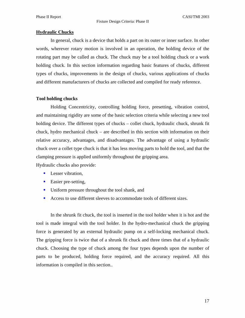
Hydraulic Chucks
In general, chuck is a device that holds a part on its outer or inner surface. In other
words, wherever rotary motion is involved in an operation, the holding device of the
rotating part may be called as chuck. The chuck may be a tool holding chuck or a work
holding chuck. In this section information regarding basic features of chucks, different
types of chucks, improvements in the design of chucks, various applications of chucks
and different manufacturers of chucks are collected and compiled for ready reference.
Tool holding chucks
Holding Concentricity, controlling holding force, presetting, vibration control,
and maintaining rigidity are some of the basic selection criteria while selecting a new tool
holding device. The different types of chucks – collet chuck, hydraulic chuck, shrunk fit
chuck, hydro mechanical chuck – are described in this section with information on their
relative accuracy, advantages, and disadvantages. The advantage of using a hydraulic
chuck over a collet type chuck is that it has less moving parts to hold the tool, and that the
clamping pressure is applied uniformly throughout the gripping area.
Hydraulic chucks also provide:
Lesser vibration,
Easier pre-setting,
Uniform pressure throughout the tool shank, and
Access to use different sleeves to accommodate tools of different sizes.
In the shrunk fit chuck, the tool is inserted in the tool holder when it is hot and the
tool is made integral with the tool holder. In the hydro-mechanical chuck the gripping
force is generated by an external hydraulic pump on a self-locking mechanical chuck.
The gripping force is twice that of a shrunk fit chuck and three times that of a hydraulic
chuck. Choosing the type of chuck among the four types depends upon the number of
parts to be produced, holding force required, and the accuracy required. All this
information is compiled in this section..
17
Phase II Report CASI/TMI 2003 Fixture Design Criteria: Phase II
Work holding chucks
Work-holding chucks are usually used in Lathes. These chucks are either manual
or power actuated. Air or oil is used to transfer power in pneumatic or hydraulic chucks
respectively. The numbers of jaws on the chuck differ according to the usage. Two-jaw,
three-jaw, four-jaw and six-jaw chucks are commonly available and they are chosen
depending upon the shape of the product and the type of operation required. The working
principles of many types of chucks are explained in this section. The information on
different manufacturers of chucks along with their product varieties is also provided for
ready reference.
Animations on Practical devices
In this part of the manual, animations of standard arrangements of jigs and
fixtures are shown. The seven animations prepared explain the arrangement of the work
holding devices for different types of operation. These have been derived from the
literature. This will facilitate the designer by providing ideas for fixture design. The
animations shown are the set-ups used for:
• radial drilling on a cylindrical work piece,
• drilling multiple holes in a leaf jig,
• milling a key way,
• straddle milling of an engine component (connecting rod),
• lapping operations on two different contoured work pieces, and
• turning operation in a lathe.
MODULE 2 Fixture Assemblies
This section makes extensive use of VRML technology to help understand
fixtures. It provides an interactive feel to designing fixtures. It contains various fixtures
built using VRML. A user can view a 3D model of the fixture and also the different
elements that make a fixture. The user is capable of zooming in the part, panning the part,
and rotating the part, as desired. The seek option in the VRML world allows the user to
actually zoom into any particular area of the 3D model. The virtual world gives a feeling
18

Phase II Report CASI/TMI 2003 Fixture Design Criteria: Phase II
as if the user is actually handling the parts. The 3D models are associated with different
views such as the top view, bottom view, right hand side view, front view and default 3D
view. Some fixtures also show some important close-up views.
The fixture assembly contains eleven fixtures obtained from Tinker AFB. These
fixtures have been reproduced in Pro Engineer® after carefully studying their
photographs acquired from Tinker shops. The photographs had to be obtained since
ready-hand drawings were not available. One reason for this was the actual interruption
of production that could have resulted if the fixture was transported. These are
specialized fixtures used for various operations such as grinding, lapping, turning and
inspection. Each of these fixtures have been designed and implemented by Tinker
Engineers. Mr. Steve Moore, Mr. Pat Grissom and Mr. Pat Harris were 3 of the fixture
designers that have designed the majority of these.
There are two grinding fixtures, four lapping fixtures, three turning fixtures, and
one inspection fixture. The complete assembly of each fixture system has been split into
different active window frames, so as to facilitate navigation in the system. While one
large frame shows the complete fixture to be assembled, another small frame presents the
individual part for 3D examination in the VRML world. The fixture and part models are
accompanied by brief explanations. The user can pick any part in the fixture assembly
window and try to assemble it. While doing the assembly, the user can study different
attributes of the fixture as well as each part, using zoom, seek, pan and rotate options in
the VRML browser. These models also include an animation option whereby the user can
see the fixture assembly rotating making it easier to visualize the assembled fixture
mounted on machine tool. Appendix contains the screen shots of different fixtures
modeled in VRML.
19
Phase II Report CASI/TMI 2003 Fixture Design Criteria: Phase II
MODULE 3
Build your own Fixture
In this module, the user will be allowed to build his/her fixture using standard
available components including locating pins, clamps, tooling plates, riser blocks, and
fasteners. The very fact that VRML can be clubbed with JAVA and HTML enhances the
capabilities of VRML. We plan to build the above system using JavaScript codes
embedded in VRML. We propose to build the fixtures using a modular fixturing system,
complete with user interaction. The modular fixturing system consists of several elements
which can be broadly classified into
• Tooling Plates and Blocks
They form the basic structure of any assembled fixture.
• Mounting Elements
These mounting elements both mount the various tooling plates to the
machine-tool table as well as the variety of tooling platform and blocks, locators,
supports and clamps to the mounted tooling plates.
• Locating Elements
Locating components are used in conjunction with the tooling plates and
mounting elements to perform a variety of different workpiece location
supporting, and positioning functions.
• Clamping Elements
These elements are used to hold the workpiece in its place during
machining. Clamps vary as per the requirement.
• Special Purpose Accessories
These are components used in special cases.
20
Phase II Report CASI/TMI 2003 Fixture Design Criteria: Phase II
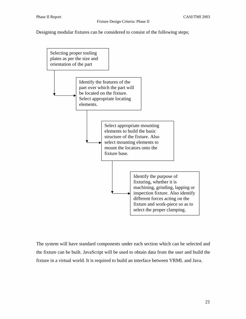
Designing modular fixtures can be considered to consist of the following steps;
Selecting proper tooling plates as per the size and orientation of the part
Identify the features of the part over which the part will be located on the fixture. Select appropriate locating elements.
Select appropriate mounting elements to build the basic structure of the fixture. Also select mounting elements to mount the locators onto the fixture base.
Identify the purpose of fixturing, whether it is machining, grinding, lapping or inspection fixture. Also identify different forces acting on the fixture and work-piece so as to select the proper clamping.
The system will have standard components under each section which can be selected and
the fixture can be built. JavaScript will be used to obtain data from the user and build the
fixture in a virtual world. It is required to build an interface between VRML and Java.
21
Phase II Report CASI/TMI 2003 Fixture Design Criteria: Phase II
COST ANALYSIS
Fixtures, based on their application, can be broadly classified into three
categories:
1) Manufacturing Fixtures
2) Repair Fixtures
3) Inspection fixtures.
These fixtures are unique and have their own specific attributes. All the same, all
fixtures need proper location and clamping.
Manufacturing fixture design can be considered to consist of the following stages:
1) Part analysis
2) Fixture Design
3) Design Analysis
4) Manufacturing
5) Measurement and Prototype testing with and without part
6) Putting fixture to production
Things to remember while designing a fixture include
1) Application of the fixture (manufacturing/repair/inspection),
2) The Number of parts for which the fixture will be used,
3) The Level of accuracy required,
4) The criticality of the part with respect to the aircraft,
5) Replaceability, reusability and discardability of the fixture, and
6) Standardization of fixtures and fixturing principles.
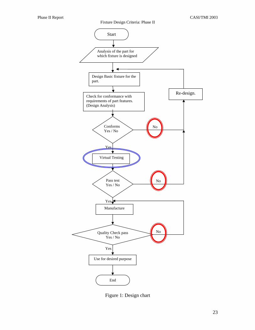
The time and money spent on a fixture should justify its use. The entire
procedure can be captured by the flow chart illustrated below. It can be seen from the
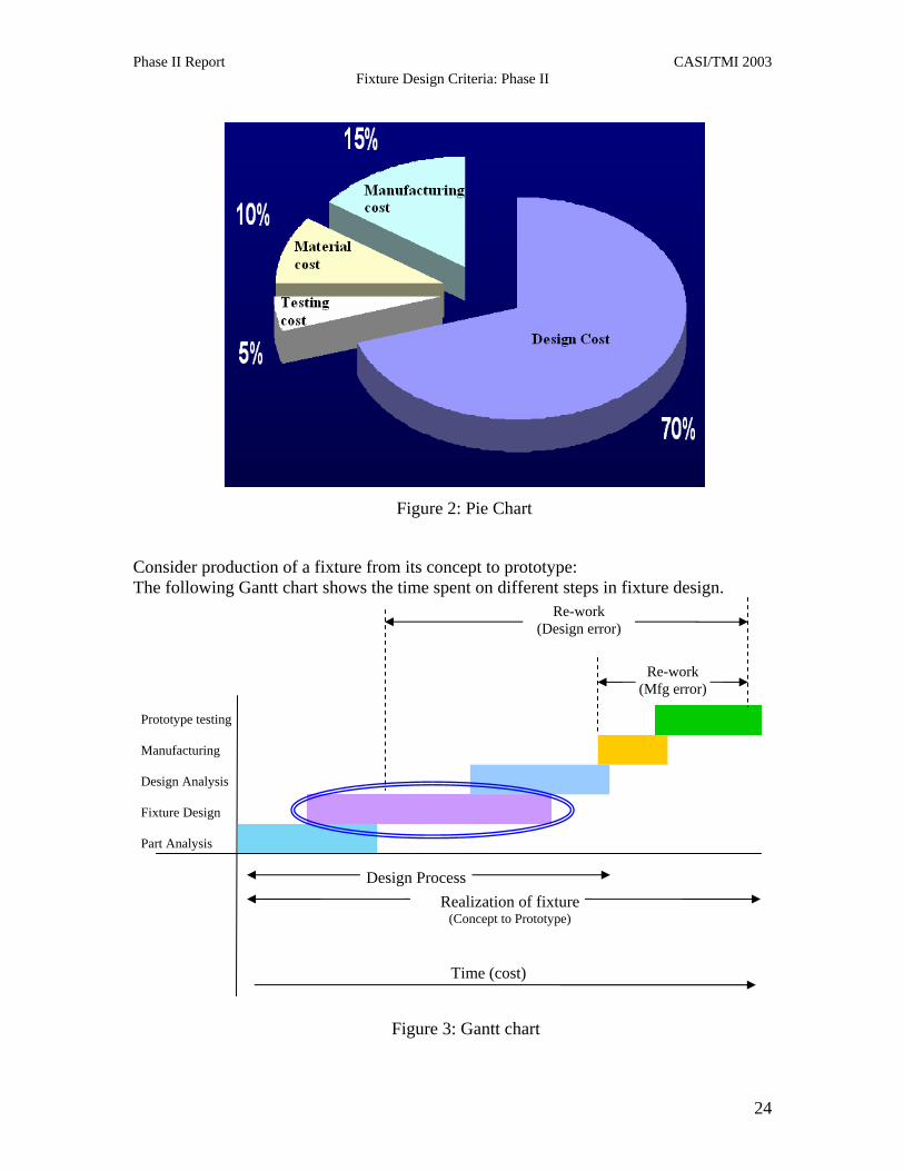
subsequent pie-chart that the time and effort is maximum for design, which is eventually
reflected in its cost. Thus reducing the design time can help in achieving much savings.
22
Phase II Report CASI/TMI 2003 Fixture Design Criteria: Phase II
Figure 1: Design chart
Analysis of the part for which fixture is designed
Design Basic fixture for the part.
Check for conformance with requirements of part features. (Design Analysis)
Conforms Yes / No
Virtual Testing
Pass test Yes / No
Manufacture
Quality Check pass Yes / No
Use for desired purpose
End
No
No
No
Yes
Start
Re-design.
Yes
Yes
23
Phase II Report CASI/TMI 2003 Fixture Design Criteria: Phase II
Consider prThe followi
Prototype test
Manufacturing
Design Analy
Fixture Design
Part Analysis
Figure 2: Pie Chart
oduction of a fixture from its concept to prototype: ng Gantt chart shows the time spent on different steps in fixture design.
ing
sis
Design Process Realization of fixture
Re-work (Design error)
Re-work (Mfg error)
(Concept to Prototype)
Time (cost)
Figure 3: Gantt chart
24

Phase II Report CASI/TMI 2003 Fixture Design Criteria: Phase II
We can say that at every non-conformance point, (marked with red circles in the flow chart) the design cost shoots up exponentially. The non-conformance cost in most cases is 100 % of what has been already spent. The Gantt chart also shows the rework time spent due to design and manufacturing errors. Work done in Phase 2 includes development of fixtures in virtual environment. The virtual environment helps the designer to virtually see each and every aspect of the fixture and its sub parts thus helping the designer to have a better understanding of the part and the subject. The standard fixtures so developed will also help fast visualization of existing fixtures without actually finding and analyzing the fixtures in reality. The virtual environment serves as a platform for analyzing the fixtures and reduces time and resources spent on actually building the fixture and then testing them. Also, much time is saved, since no fixtures need to be analyzed physically. Using the same cost analysis as used for Phase 1, we consider that a fixture is realized over a span of 60 days, of which nearly 40 days are spent on designing a fixture. It should be also kept in mind that for that period of time few aircrafts costing 15 million each are sitting idle. Estimate for cost of fixturing for 100 fixtures for 50 aircrafts: Assume 50 design engineers are working over them for 2 months at a rate of $50 per hour. Total man hours for 45 days for 50 design engineers = 18,000
Cost for design engineers = $900,000.00 +
Cost of planes idle for 60 days = $1,235,000.00 Of the fleet of 84 let us consider 25 are under routine or breakdown maintenance) (25 aircrafts of average 30 million per craft at rate of (1% annually) 0.000028% per day) Total design cost over span of 2 months = $2,135,000.00 Consider that there is a 30 % non conformance of fixtures. The production lines get overloaded by at least 40%; however the increase in lead-time increases the cost (due to idle aircrafts) by 30 %. 30% crafts stay idle for 30 more days = $600,000.00 + Cost of non-conformance (man power) = $270,000.00 + Cost of overload on other machinery (40% of total cost) = $854,000.00 Total Cost of non conformance = $ 1,724,000.00 Total cost incurred for batch in 2 months = $3,859,000.00 The blue ovals in the flow chart and the Gantt chart indicate the areas where significant improvement can be achieved. We just consider a 5% improvement in those areas. Much
25

Phase II Report CASI/TMI 2003 Fixture Design Criteria: Phase II
time and money is also saved using proper guidelines for fixturing. Use of virtual environment not only saves time, but also enhances the learning experience. Estimate of money saved: (We used the same cost analysis used for Phase 1 with increased savings due to use of the proposed Virtual Environment) If at least 20% time is saved by proper Design guidelines, the initial design cost reduces to = $720,000.00 Cost of idle aircrafts reduces to = $988,000.00 The cost of non-conformance if not completely eliminated is reduced to 1-5%. Cost of idle Aircrafts (due to reduced lead time) = $90,000.00 + Reduced cost of non-conformance (Manpower) = $85,400.00 + Reduced overload on machinery = $106,750.00 Cost of non conformance reduces to = $282,150.00 (Increased time for aircrafts, non-conformance cost, Cost of overloading the system) Thus new fixture design cost = $1,990,150.00
1,724,000.00
1,235,000.00
900,000.00
282,150.00
988,000.00
720,000.00
268,000.00
938,600.00
684,000.00
0.00500,000.00
1,000,000.001,500,000.002,000,000.002,500,000.003,000,000.003,500,000.004,000,000.00
Cos
t $
Cost Analysis
Man Hours 900,000.00 720,000.00 684,000.00Idle Aircrafts 1,235,000.00 988,000.00 938,600.00Non Conformance 1,724,000.00 282,150.00 268,000.00
Initial Cost Revised Cost 1
Revised Cost 2
Considering the total cost further reduces by 5%, we have a total cost = $1890642.00
26

Phase II Report CASI/TMI 2003 Fixture Design Criteria: Phase II
Thus total saving = $ 3,859,000.00 – 1,890,642.00
(Over of Span of 2 months) = $ 1,968,358.00
Annual Saving = $11,810,148.00
These numbers are hypothetical and have been used to demonstrate ball-park cost
savings rather than perform an actual cost analysis. All the same, it can be seen that
substantial monetary gains can be realized by the development of a virtual design tool
that cuts down the design cycle.
CONCLUSIONS
This report provides a brief synopsis of the work undertaken to build an on-line fixture
design roadmap. This roadmap, over the course of the two phases completed, has
evolved from a pure paper manual to a fully-documented, interactive, computerized soft-
manual showing the basic principles and components of fixturing. Animations and
manipulability of fixture elements using established fixture designs allow the user to
better understand the principles of design. During Phase III this manual will be further
developed to interactively design modular fixtures for different workparts. We believe
that such a system will be useful to operators, engineers and managers who are in-charge
of setup reduction and fixture design.
27

Phase II Report CASI/TMI 2003 Fixture Design Criteria: Phase II
APPENDIX
28
Phase II Report CASI/TMI 2003 Fixture Design Criteria: Phase II
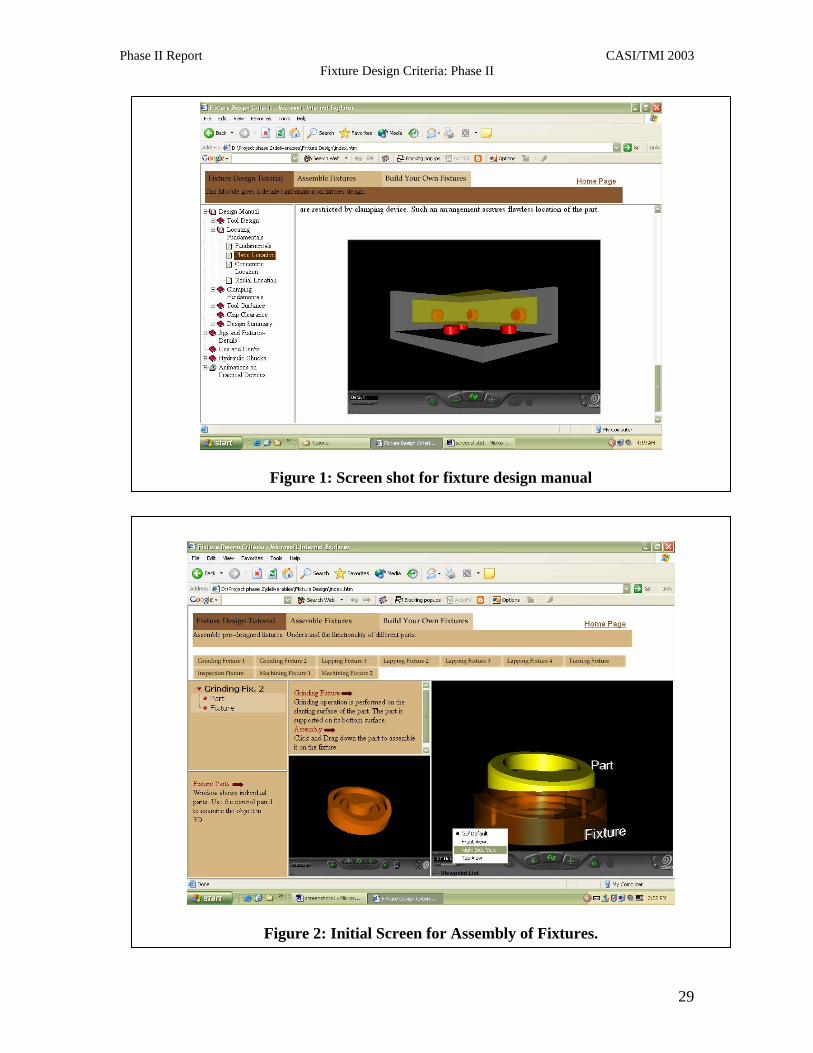
Figure 2: Initial Screen for Assembly of Fixtures.
Figure 1: Screen shot for fixture design manual
29
Phase II Report CASI/TMI 2003 Fixture Design Criteria: Phase II
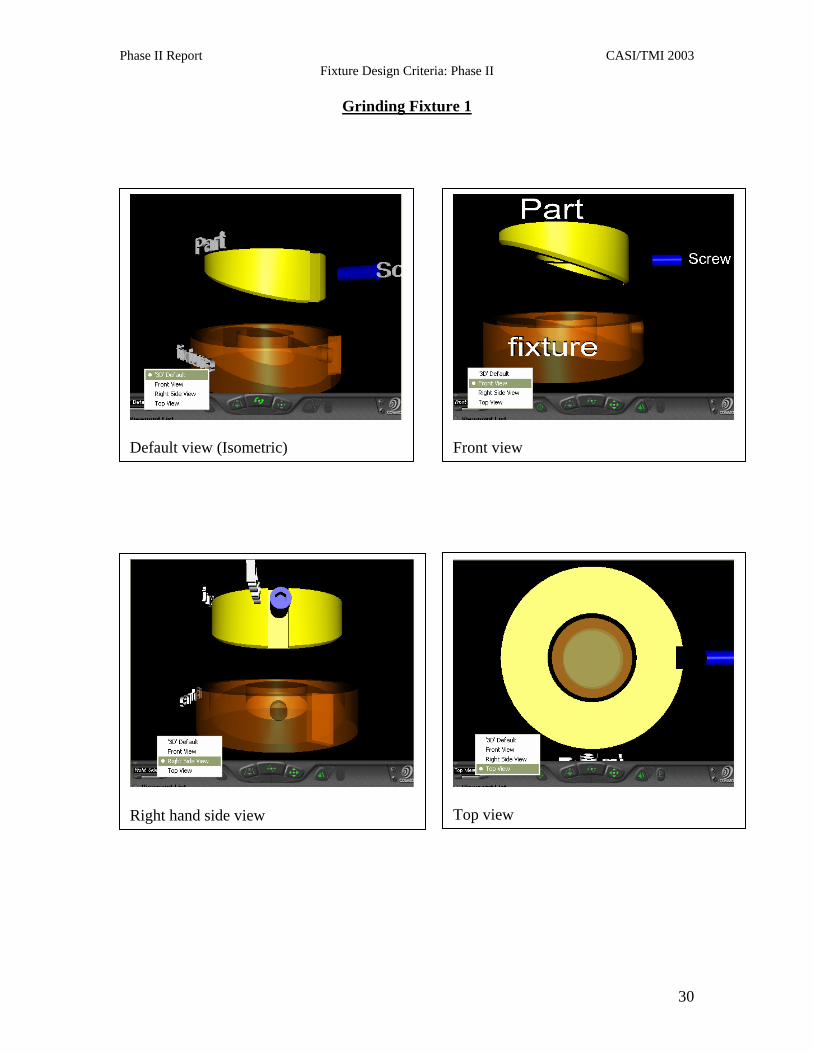
Grinding Fixture 1
Default view (Isometric)
Front view
Right hand side view
Top view
30

Phase II Report CASI/TMI 2003 Fixture Design Criteria: Phase II
Grinding Fixture 2
Default view (Isometric)
Front view
Right hand side view
Top view
31
Phase II Report CASI/TMI 2003 Fixture Design Criteria: Phase II
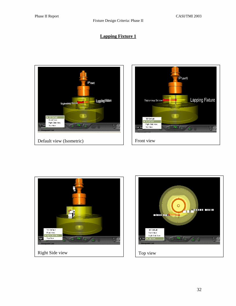
Lapping Fixture 1
Default view (Isometric)
Front view
Right Side view
Top view
32
Phase II Report CASI/TMI 2003 Fixture Design Criteria: Phase II
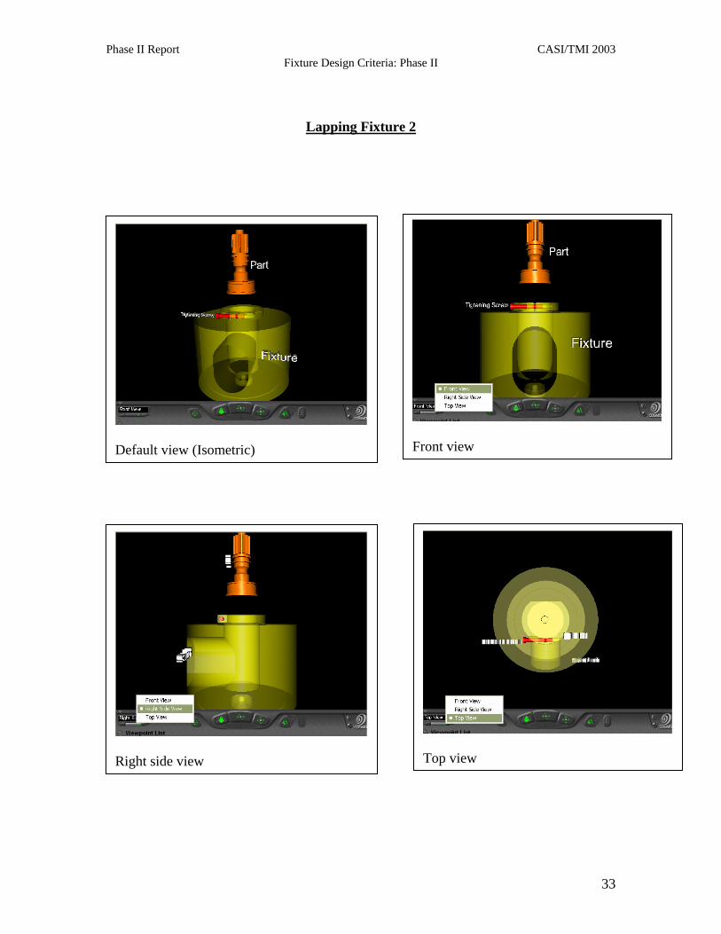
Lapping Fixture 2
Default view (Isometric)
Front view
Right side view
Top view
33
Phase II Report CASI/TMI 2003 Fixture Design Criteria: Phase II
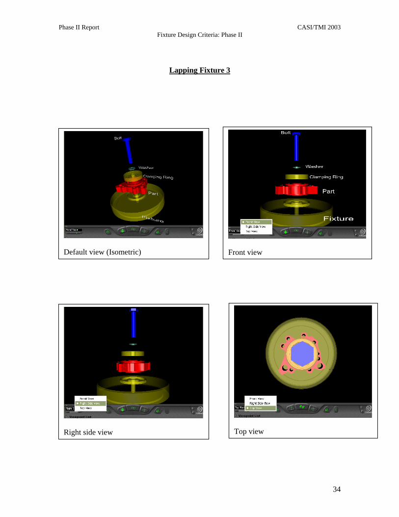
Lapping Fixture 3
Default view (Isometric)
Front view
Right side view
Top view
34

Phase II Report CASI/TMI 2003 Fixture Design Criteria: Phase II
Lapping Fixture 4
Default view (Isometric)
Front view
Right side view
Top view
35
Phase II Report CASI/TMI 2003 Fixture Design Criteria: Phase II
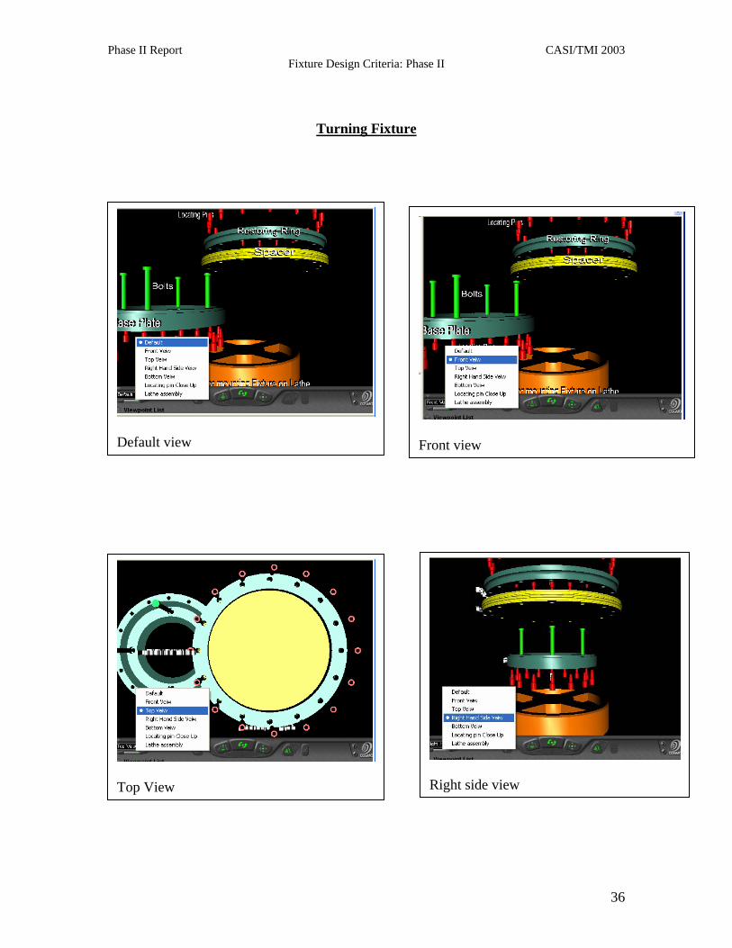
Turning Fixture
Default view
Front view
Top View
Right side view
36

Phase II Report CASI/TMI 2003 Fixture Design Criteria: Phase II
Bottom view
Specialized view of locating pin
Assembly over the lathe (Horizontal)
37

Phase II Report CASI/TMI 2003 Fixture Design Criteria: Phase II
Inspection Fixture
Default view (Isometric)
Front view
Specialized view – Close up of Clamp
Bottom view
38
Phase II Report CASI/TMI 2003 Fixture Design Criteria: Phase II
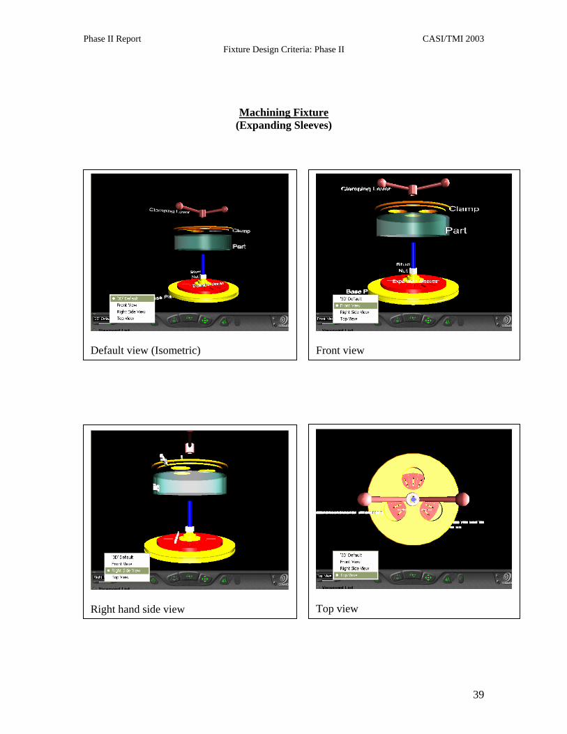
Machining Fixture (Expanding Sleeves)
Default view (Isometric)
Front view
Right hand side view
Top view
39
Phase II Report CASI/TMI 2003 Fixture Design Criteria: Phase II
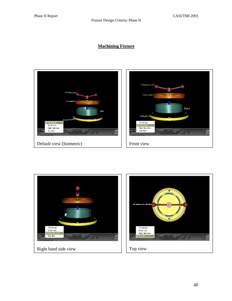
Machining Fixture
Default view (Isometric)
Front view
Right hand side view
Top view
40