maasbusinesscase.commaasbusinesscase.com/business case/new western sydney museu… · web...
TRANSCRIPT

JOHNSTA
Attachment H:Infrastructure

Warren Smith 8 Partners
PROJECT # 5486000
ISSUE For Approval
DATE 29 September 2016
REVISION 1
AUTHOR N. Meo
REVIEWED BY M. Cahalane
STATUS Current
161Museum of i l i kS Applied Arts& Sciences
PREPARED BY:
WARREN SMITH & PARTNERS PTY LTD
Consulting Engineers
ACN 002 197 088 ABN 36 300 430 126
1st Floor, 123 Clarence Street
Sydney 2000 NSW Australia
T 02 9299 1312 F 02 9290 1295
Warren
Smi th 8
Par tners
PREPARED FOR:
MUSEUM OF APPLIED ARTS & SCIENCES
Contemporary Museum
ABN 59 354 516 818
500 Harris St
Ultimo 2007 NSW Australia
T 02 9217 0111
· Hydraulic Services • Fire Protection X Civil Engineering IN Sydney Water Accredited Water Servicing Co-ordinator • Design Project Management - Building Plan Approvals

Warren Smith 8 Partners
CIVIL ENGINEERING SERVICES1. INTRODUCTION
Warren Smith & Partners (WS+P) has been engaged by the New Museum to prepare a services
investigation report of the infrastructure located in close proximity to the MAAS development. The
purpose of the investigation is to ascertain what services will be affected by the proposed development
and to provide a recommendation on what works are required, if any, in terms of diversions and
connections to ensure that there is sufficient access to water with appropriate pressures. WS+P will also
make recommendations on the required infrastructure extensions/amplifications that will need to be
installed in order for the development to be served by sewer, water, and gas
The following tasks were undertaken in relation to gathering information for the purposes of this
investigation:-
· Receipt and checking of the proposed development plan with the existing services drawings;
· A 'Dial Before You Dig' services search, and;
· Report providing recommendation on the works required.
The following upgrades have been recommended to facilitate the proposed development:-
· Amplification of the existing DN150 watermain in Phillip Street to DN200 between the front of the
property and Church Street;
· Deviation of the existing DN225 sewer mains within the development site, and;
· Deviation of the existing DN150 sewer mains within the development site.
1.1 PROPOSED DEVELOPMENT
The proposed development will see the relocation of MAAS, including all museum pieces, from its
location in Ultimo to Parramatta. The proposed site is bound by Wilde Avenue to the east, Phillip St
to the south and the Parramatta River to the north. It is located approximately 500m north of the
Parramatta CBD. Currently, the site is used as a multi-storey carpark with small commercial
properties facing Phillip St.
Please refer to Figure 1 for an aerial view of the development site area.
n Hydraulic Services ■ Fire Protection 0 Civil Engineering 0 Sydney Water Accredited Water Servicing Co-ordinator • Design Project Management - Building Plan Approvals
a2

Warren Smith 8 Partners
2. DATA COLLECTION
2.1 SYDNEY WATER HYDRA DATABASE DRAWINGS
WS+P has obtained Sydney Water's Hydra database to assess the available water and sewer
infrastructure in close proximity to the development site.
Please find attached in Schedule 2, the following drawing:-
· Sydney Water Hydra plan at Scale 1 in 1500 which shows the development site on the
northwest corner of Phillip St and Wilder Ave.
The database has shown that the development site has frontage to two (2) Sydney Water water
assets on the southern side of the development site along Phillip St:-
· A DN900mm trunk water main, and;
· A DN150mm water main.
The following Sydney Water water asset is also located on the western side of the development
site along Church St:-
· A DN375 water main
The following Sydney Water sewer assets have also been identified within the development site:-
· A DN525 main which reticulates across the development site parallel to the Parramatta River;
· Two (2) DN225 mains which reticulate in a north south direction across the development site;
· Two (2) DN150 mains which reticulate east across the development site, and;
· A DN500 main which runs under the bridge crossing in Parramatta River.
Please refer to Figure 2 for details.
n Hydraulic Services ■ Fire Protection ■ Civil Engineering • Sydney Water Accredited Water Servicing Co-ordinator Design Protect Management - Building Flan Approvals
>4

105M x 110MM ST
Warren Smith 8 Partners
2.2 JEMENA GAS DIAGRAM
The Jemena diagram received illustrates that there are no network mains traversing the site. The
following is a list of gas networks which run along Phillip St as illustrated in Figure 3.
Please find attached in Schedule 3, the following drawing:-
· Jemena Gas Diagram plan at Scale 1 in 2000.
The database has shown that the development site has frontage to two (2) Jemena assets along
Phillip St:-
· A DN150mm high pressure 1050 kPa secondary main that runs along Phillip St and crosses
to the opposite side of Parramatta River, and;
· A DN110mm low pressure 7 kPa nylon network main.
Please refer to Figure 3 for details.
Figure 3: Jemena Assets (Source: Jemena)
n Hydraulic Services ■ Fire Protection ■ Civil Engineering M Sydney Water Accredited Water Servicing Co-ordinator -Design Project Management - euwe g Plan Approvals

>6

OPTION 1 -
SEWERMAINS TO
OPTION 2 -
114 / · I I /
SEWERMAIN DEVIATION
Figure 5: Proposed Sewer Main Connection and Deviations (Source: Sydney Water)
CONNECT INTO
INTERCEPT AND
DN525 SEWER
Warren Smith Partners
3.1.2 SYDNEY WATER SEWER MAINS
Multiple sewer mains have been noted within the development site. As per Sydney
Water's previous correspondence with AECOM, connections to the DN525 main can be
made through extensions to existing manholes. However, the DN525 main may require
amplification depending on when developments related to the wider Parramatta CBD
area will be occurring. These developments include the relocation of the DN500 main
crossing Parramatta River which will impact future DN525 capacity.
In order to facilitate the proposed museum footprint, the DN225 and DN150 sewer mains
will need to be deviated. Option 1 to deviate the DN225 sewer main involves intercepting
the main and deviating it north to connect into the DN525. Option 2 to deviate the DN225
sewer main involves intercepting the main, deviating it south and reticulating it along
Phillip St before connecting into the DN450 main located in Wilde Ave. The DN150 sewer
main is to be intercepted and deviated south to connect into the DN225 sewer deviation
along Phillip St. The DN150 which runs through Oyster Lane is to be removed and a new
connection to the lots established from the proposed deviation is to be made through
Phillip St and Wilde Ave.
Please refer to Figure 5 below for details.
· Hydraulic Services • Fire Protection 1111 Civil Engineering MI Sydney Water Accredited Water Servicing Co-ordinator -Design Protect Management - Building Pan Approvals
>$

Warren Smith 8 Partners
4. COST ESTIMATES
4.1 WATERMAIN
The existing DN150 watermain along Phillip Street, from the front of the proposed new building to
Church Street, shall be amplified to a DN200 watermain. Please refer to Table 1 below for a cost
estimate of the proposed watermain.
Table 1: Watermain Amplification Cost Estimate
Item Quantity Unit Rate Total
Amplification of existing DN150 to DN200 170 m j $1,500 r$255,000
4.2 SEWERMAIN
It is proposed that the existing DN225 and DN150 sewers within the development site be deviated
in order to facilitate the new building footprint. Please refer to Figure 5 in Section 3.1.2 for the
proposed sewer main deviations.
4.2.1 EXISTING DN225 DEVIATION
Option 1 involves intercepting and deviating the existing DN225 sewer main north for
approximately 64m and connecting into the existing DN525 sewer main running along the
north of the property.
Option 2 involves intercepting and deviating the existing DN225 sewer main south to
Philip Street, reticulating it east and connecting into the existing DN450 sewer main in
Wilde Avenue. This sewer main deviation option is approximately 272m in total.
n Hydraulic Services ■ Fire Protection SI Civil Engineering
Sydn
ey

Wate
r
Accre
dited
Wate
r
Servi
cing
Co-
ordin
ator -
Desig
n
Project
Manag
ement
-
Buildin
g Plan
Appro
vals >
10

Warren Smith Er Partners
SCHEDULE 1
PROPOSED LOT SURVEY

n Hydraulic Services ■ Fire Protection ■ Civil Engineering Si Sydney Water Accredited Water Servicing Co-ordinator Design Project Management - Building Plan Approvals
> 12

Warren Smith 8 Partners
SCHEDULE 2
WATER HYDRA

n Hydraulic Services ■ Fire Protection i Civil Engineering S Sydney Water Accredited Water Servicing Co-ordinator -Design Project Management - Building Plan Approvals
> 1 3

Warren Smith a Partners
SCHEDULE 3
GAS DIAGRAM

· Hydraulic Services W Fire Protection If Civil Engineering U Sydney Water Accredited Water Servicing Co-ordinator -Design Ana Management • Bu!ding Plan Approvals
> 14

Warren Smith Er Partners
SCHEDULE 4
WATER PRESSURE FLOW

n Hydraulic Services IIII Fire Protection it Civil Engineering 51 Sydney Water Accredited Water Servicing Co-ordinator -Design Project Management &Aiding Plan Approvals
> 1 5

Sydney
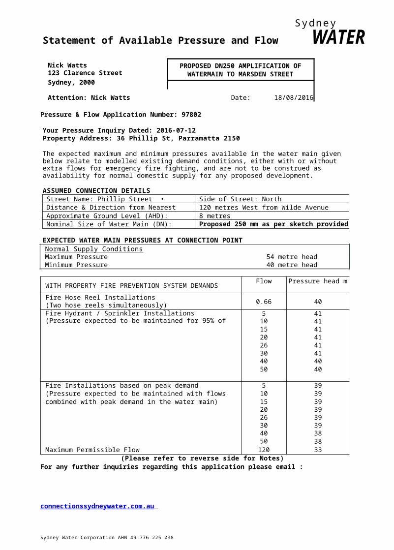
Statement of Available Pressure and Flow WATERNick Watts PROPOSED DN250 AMPLIFICATION OF123 Clarence Street WATERMAIN TO MARSDEN STREETSydney, 2000
Attention: Nick Watts Date: 18/08/2016
Pressure & Flow Application Number: 97802
Your Pressure Inquiry Dated: 2016-07-12Property Address: 36 Phillip St, Parramatta 2150
The expected maximum and minimum pressures available in the water main given below relate to modelled existing demand conditions, either with or without extra flows for emergency fire fighting, and are not to be construed as availability for normal domestic supply for any proposed development.
ASSUMED CONNECTION DETAILSStreet Name: Phillip Street • Side of Street: NorthDistance & Direction from Nearest Cross Street 120 metres West from Wilde AvenueApproximate Ground Level (AHD): 8 metresNominal Size of Water Main (DN): Proposed 250 mm as per sketch provided
EXPECTED WATER MAIN PRESSURES AT CONNECTION POINTNormal Supply ConditionsMaximum Pressure 54 metre headMinimum Pressure 40 metre head
WITH PROPERTY FIRE PREVENTION SYSTEM DEMANDSFlow Pressure head m
Fire Hose Reel Installations(Two hose reels simultaneously) 0.66 40
Fire Hydrant / Sprinkler Installations 5 41(Pressure expected to be maintained for 95% of the time) 10 41
15 4120 4126 4130 4140 4050 40
Fire Installations based on peak demand 5 39(Pressure expected to be maintained with flows 10 39combined with peak demand in the water main) 15 39
20 3926 3930 3940 3850 38
Maximum Permissible Flow 120 33(Please refer to reverse side for Notes)
For any further inquiries regarding this application please email :
connectionssydneywater.com.au
Sydney Water Corporation AHN 49 776 225 0381 Smith St Parramatta 2150 PO Box 399 Parramatta 2124 I DX 14 Sydney T 13 20 92 I www.sydneywater.com.au

Delivering essential and sustainable water services for the benefit of the community

Johnstaff Projects November 2016The New Museum, Parramatta — Flood Study 161372
Appendix A
Topographical Survey and site Images
Taylor Thomson Whitting (NSW) Pty Ltd Appendix A© Taylor Thomson Whitting
RIV
PARRAMAT
urs
O p 7 1 t
4:1 DP 393866
MERITON
MULTI-
PRELIMINARY
0 S
$ ;
0 3 1 4 5 9
S
L PARRMARL CRS
ArvD LEVELS OVER LA. AI INEOF DETAILCORNER OF MLLE
Palvvv• 'MuAHD 11 .69,”

1
. DP
"
PRELIMINARY
Perneel,r11° 11 /03 ;4 7 . 1:5 RAN Oi 01 P5 CORNER OF PKV 57.13.7,

Johnstaff Projects November 2016The New Museum, Parramatta — Flood Study 161372
Appendix B
evein n, Pr
Taylor Thomson Whitting (NSW) Pty Ltd Appendix B© Taylor Thomson Whiffing

11 A BASEMENT LEVEL page . 3LANDSCAPED
'1'714 Rio
is Public Space4,949 m2
Security + Ticketing
Touring Hall Prep.
Space250 m2
40 Circulation + Processing 1,949 m2
41 Carparking (20 CARS) 875 m2
§ Public Lift13 m2
i l n r n i Z f t
i § Art11ft
s A r t / S t a f f L i f t
PEDESTRIAN CP061LTION
PEDESTRIAN CIRCULATIO
f",7,57-717/177/7-
RL
CONTENTS BASEMENT PLAN 1:500 @ A3 0
OPTION 1 I BASEMENT LEVEL I 2/11/2016
RETA
4 1 N I /
ACCESS FROM

2.3 GROUND LEVEL 13/1R,9,1444 r_r4
— page. 36LANDSCAPED OUTDOOR
PLJBUC SPACE
CONTENTSPHILLIP STREET
GROUND FLOOR PLAN 1:500 @ A3 0
OPTION 2 I GROUND LEVEL I 2/11/2016
2
3 6
t3 rn2 Arrivals Foyer 3111.2o riffi
Bag g.nCheck50 :13
-‘13
c,Izting
Security50 m2
41:1,-:cnt.1 Space
g Cafe
568 m2
g leeC af7r,2Kitchen/0 Kitchen Store
2 0 rerri,2ts Kitchen1 5 0 ,
§ Visible,2,,
Collections int
Tostic4inmg2 Gallery
§ Touring Retail
is Ilfset'it
ig max17 Bus Bay
mitilefpn.lig Labs
· Resource Centre 398 m2
n 4:,.1;13i1,/: 21 s
Foyer
iIlgesi7 ,c.alent
Offices
250 m2
®WC132 m2WC
al Public Lift
EIN4ozArt/Staff Lift is Art
Lift50 m2
1111 5Aort,vLift
34 Ri r,r147 ,2
39 Riser
PEDESTRI
2
15 000 \AV
L 1RETAISI 9cuss TO EXISTING

LEVE
P
LEVEL 3
Collection Storage
Offices
LEVEL 2
Collection Storage Main
Galleries
LEVE
Main
LEVEL 0
Commercial/Omni
Touring
LEVEL -1 BASEMENT
Carparking
2.9 3D MASSING
Option 2 captures the base requirements of the FDB, with the omission of the Touring Gallery B. This concept envisages utilisation of the entire site and
snot retain the heritage items of VVi..JW Grove or St George's Terrace. The total briefed floor area for this concept is comparable to the current space of the Powerhouse Museum.
LEVEL 4 page. 47PlantLEVEL 3
WorkshopsBioBox
Circulation
LEVEL 2Collection Storage
Auditoriums
Circulation
LEVEL 1Main Galleries - Large ScaleCollection Storage
Children's Gallery
Circulation
LEVEL 0 GROUNDArrivals Hall, Security + Ticketing
Loading Dock + Bus BayEducation Labs
CirculationLEVEL -1 BASEMENT
Circulation + ProcessingSecurity + Tcketing
Public Space
MI
:=1"XS JOHNSTAFF FENDER KATSALIDIS MIRAMS ARCHITECTS OPTION 2 I 3D MASSING I 2/11/2016

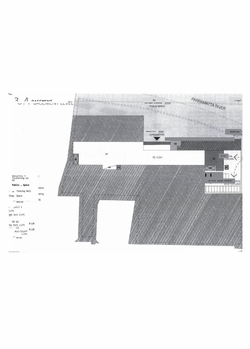
3.4 BASEMENT
PEDEST
11 42 ACCESS FROM
CONTENT BASEMENT LEVEL PLAN 1:500 @ A3 Q
39DSCAPED
page.
PEDESTRI
WIPE 7' 'f'flrf--1,7,:,,v/f-'/7',7/V/-7'1, e/pw
RETA
Security + Ticketing eo m2
Public 9 Space
· 250 Touring Hall Prep. Space
41 Circulation + Processing 1,929 m2
42 Carparking (20 CARS)
· raulnl c Liftgo Art IJft
50 m2Ng Art Lift••• -12
Art/Staff Lift
11,1 .4 ,on;Art/Staff Lift 48
OPTION 2A I BASEMENT LEVEL I 2/11/2016

4.3 GROUND LEVEL page. LANDSCAPED
CIRCULATI
pPEDESTRIAN- 1-7;1 /3/1.//i,
7914 e rn2ntral Gallery
is Tech. Space2 0
I I 'MAX
Tourin953 g Gallery B
1111 Touring, B Retail
c 1 Touring Gallery A
§ Touringn.2 A Retail
§ Arrivals1=
Foyer 968 4
Office
1
4 R
§ Learning Labs
1,152 Resource
Centre
Production414 r¢n2 Studio
2
3▪ 120e0siLlent
OfficesW C
n7 4BagrarCheck2 1 Arrivalsz Foyer
129 Loading Dock2 6 5 Security + First Aid
" asfe
s m2 11111A12512
34 .v5erzs KitchenL _BELAU &CUSS
TO
Art Lift·
52 n12
· 5Aortrl_ift
§ Non-Art/Staff,2
Lift
7 nft • Non-Non-Art/Staff
Lift ▪ Art/Staff Lift
· Visible
37 Bus Drop-off
309 512
mi 2Public
Lift4° R45iser
2
41 RiIg
nsE,3;
CONTENTS PHILLIP GROUND LEVEL PLAN 1:500 @ A3 0
OPTION 3 I GROUND LEVEL I

MI
___—.-------,,,> „ , , , ,
< - - - - - - - - : : - : 1 i
"->-, --,, . _____________ I 1
......,`"'N'''''—'-.r.1 I
I II i '--..Iit
LEVEL 4 page.
Circula
LEVEL 3
OffiAuditoriu
LEVE
Collection
O
Main
LEVEL 1 Workshops
Children's
Main
LEVEL a
Loading Dock + Bus
Education
LEVEL -1
Public
LEVE
P
LEVE
Collection
CirculationLEVEL 2
Main Galleries
Circulation
LEVEL 1
Service
LEVEL 0
Willow Grove: Cafe +
Touring
LEVEL -1 BASEMENT Touring Gallery Prep. Space
4.1 0 3D MASSINGOption Three captures the entire requirements of the FDB, including both the Omnimax and Touring Gallery B. This concept envisages
· ''-ation of the Willow Grove and .3eorge's Terrace.
The total briefed floor area for this concept is greater than the
current space of the Powerhouse Museum.
Circulation in this option has been increased, as the main entrance and arrivals hall has been pushed to the east of Willow Grove, separating it further from the museum spaces on the west of the site. The entire built form has moved forward towards the river to accommodate the retention of Willow Grove and St. George's Terrace, decreasing the river bank area available for public space and access.
FENDER KATSALIDIS MIRAMS ARCHITECTS OPTION 3 I 3D MASSING I 3/11/2016
e m . . . 1 0 1 1 , 1 1 1 1 t a t i f t ,- - • - N reel
'1-T*ft"'*--ZgkORgr
r • inoti
\ %IN M7(,.virampssiuftim. _________________ · B‘onkAlk rriO

CARPARK
Public
PEDESTR
i
Circulation +
rr M
e b
N TS SKETCHES I CARPARK OPTION I

1174.7zwiv
mV
firaliteriviffLe9endie=_A l l _ Ground Gontowe (made AHO) -
Upper Parramat la R iver Cross Sect ion
· Stormwater- Stornmater Pipe NetworkME 20 Year Flood (Upper Parronatia River) 1111111 20 Year Flood (Lower Plummets River) III 100 Year Flood (Upper Parremetle River) MN 100 Year Flood (Lower Parrametta River) OM na PMF (Lower Remed& firi
libillgjg/Jew_
..111 TIP
r
..4414,4„- \Avg..,-.7?.4.fariti
-
s
1e
need
is=umaimiumnal r
M I E 1 1 1 1 1 1 8 1 v M 1 1 3 1 1 1 = 1 1 1 1 E i ll M E M =
EMMEIIIMENNI=1;·
=11111ECNINECIIICEI NE131111113MMEEEMEEIr
ESEMENIM13111331WESIIIIIEEINW13111Eall 4111i.
IEZIONIESMIEDINCEM INEMENEEMIIECIE1121111

lE=MMEIMINEENIEEMI INEZINE:1311111EM 11,1111111FilkNOTE: The Upper and Lower Parmmatta River Flood Stud les are current bein u dated. Flood levels in this area ma chan e