case-vlans.pdf
TRANSCRIPT

The Case for Virtual Local Area
Networks (VLANs)
1-800-COURSES www.globalknowledge.com
Expert Reference Series of White Papers

IntroductionIn the history of Ethernet, the virtual LAN is a recent addition. The VLAN was introduced to solve a number ofnetworking issues. In this whitepaper you will learn about the evolution of Ethernet, the reasons VLANs wereintroduced, and the ways that VLANs can be used. You will also learn about the networking standards thataddress the VLAN implementation.
EthernetAs a local area networking protocol, early Ethernet was inex-pensive to install and operate when compared to competingprotocols such as Token Ring and Arcnet. It operated as a sim-ple bus architecture using an access method known as CarrierSense Multiple Access with Collision Detection or CSAM/CD. Asimple contention protocol, CSMA/CD required that stations“listen” for transmissions on the coaxial cable based networkand only transmit if no other transmissions were heard. If twoor more devices transmitted at the same time, a collisionoccurred and the devices were required to transmit again.Ethernet worked well with a few networked devices but as net-works grew, CSMA/CD turned out to be a protocol with a prob-lem. Too much traffic caused too many retransmissions, andthe efficiency of the network declined.
Figure 1. Coaxial Cable-Based Ethernet
To simplify the installation of Ethernet networks, a change wasmade to the network topology. Networks were converted fromcoaxial cable to twisted pair cabling by introducing a new deviceinto the network. That device is called a hub. The purpose of thehub was to repeat signals transmitted to it so that all devicesattached to the hub reacted as if they were still attached to coaxi-al cable. The hub did nothing to remove the problems associatedwith CSMA/CD. If anything, because it was easy to interconnecthubs or add additional networking devices to a hub, networksbecame more crowded. A solution to the problem was necessary.
Figure 2. Hub-Based Twisted Pair Ethernet
Ted Rohling, Global Knowledge Instructor, CISSP
The Case for Virtual Local AreaNetworks (VLANs)
Copyright ©2007 Global Knowledge Training LLC. All rights reserved. Page 2
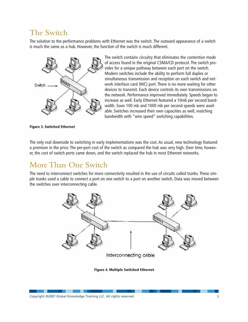
The SwitchThe solution to the performance problems with Ethernet was the switch. The outward appearance of a switchis much the same as a hub. However, the function of the switch is much different.
The switch contains circuitry that eliminates the contention modeof access found in the original CSMA/CD protocol. The switch pro-vides for a unique pathway between each port on the switch.Modern switches include the ability to perform full duplex orsimultaneous transmission and reception on each switch and net-work interface card (NIC) port. There is no more waiting for otherdevices to transmit. Each device controls its own transmissions onthe network. Performance improved immediately. Speeds began toincrease as well. Early Ethernet featured a 10mb per second band-width. Soon 100 mb and 1000 mb per second speeds were avail-able. Switches increased their own capacities as well, matchingbandwidth with “wire speed” switching capabilities.
Figure 3. Switched Ethernet
The only real downside to switching in early implementations was the cost. As usual, new technology featureda premium in the price. The per-port cost of the switch as compared the hub was very high. Over time, howev-er, the cost of switch ports came down, and the switch replaced the hub in most Ethernet networks.
More Than One SwitchThe need to interconnect switches for more connectivity resulted in the use of circuits called trunks. These sim-ple trunks used a cable to connect a port on one switch to a port on another switch. Data was moved betweenthe switches over interconnecting cable.
Figure 4. Multiple Switched Ethernet
Copyright ©2007 Global Knowledge Training LLC. All rights reserved. Page 3

Multiple switches could be connected together to form complex switching architectures. Cisco pioneered thenaming of theses complex networks by defining the location of the switch by function into a hierarchy. Clientswere directly attached to “access” switches. Access switches were connected to “distribution” switches anddistribution switches were attached to “core” switches. The transportation paths could be well- defined andcontrolled by using this technique.
Figure 5. Hierarchical Switching Model
It’s an IP WorldIn the examples we have presented so far, all of the devices are found in the same Ethernet broadcast domain.If one device sends out a broadcast packet, all of the devices connected to the switches will receive the traffic.That’s an Ethernet rule for how traffic passes through switches. That environment also creates an IP network orsubnet.
In most practical networks, all devices in a small business or enterprise network are not located on the sameEthernet network broadcast domain. We separate the networks to limit broadcast traffic among the devices orto create islands of security where devices are isolated into workgroups, departments or other similar struc-tures. Traffic from one workgroup should not be visible to another workgroup’s devices. Ethernet switches, aswe have seen so far, do not have the ability to limit the traffic. A special feature of modern switches allows usto isolate traffic so that it is limited and secure. That feature is the Virtual Lan or VLAN.
The VLANThe initial creation of a VLAN is done in the switch. For example, a small business has a single switch with 24Ethernet ports. To separate the accounting department from the engineering department, the administratorallocates switch ports to the two departments. In the switch configuration, the administrator configures ports1-12 for the accounting department and ports 13-24 for the engineering department. The configuration essen-tially creates two independent switches within the single device.
Copyright ©2007 Global Knowledge Training LLC. All rights reserved. Page 4
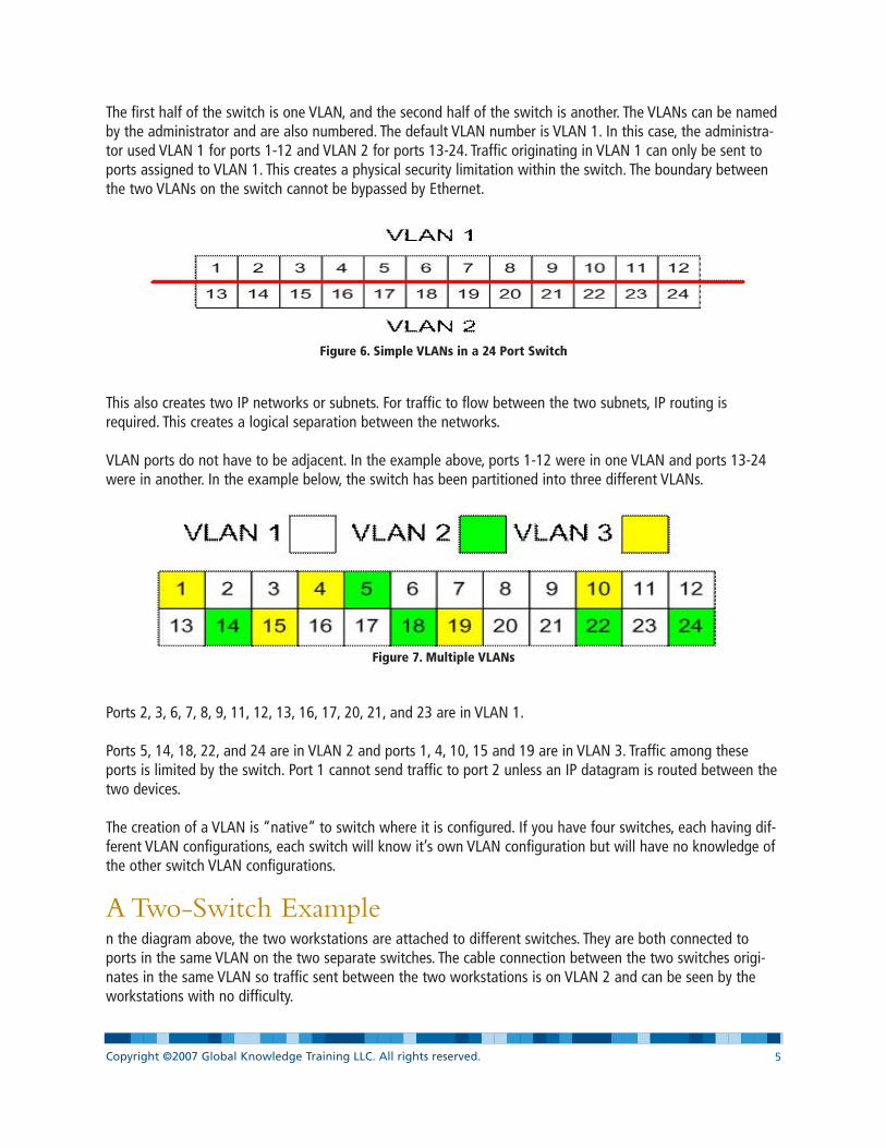
The first half of the switch is one VLAN, and the second half of the switch is another. The VLANs can be namedby the administrator and are also numbered. The default VLAN number is VLAN 1. In this case, the administra-tor used VLAN 1 for ports 1-12 and VLAN 2 for ports 13-24. Traffic originating in VLAN 1 can only be sent toports assigned to VLAN 1. This creates a physical security limitation within the switch. The boundary betweenthe two VLANs on the switch cannot be bypassed by Ethernet.
Figure 6. Simple VLANs in a 24 Port Switch
This also creates two IP networks or subnets. For traffic to flow between the two subnets, IP routing isrequired. This creates a logical separation between the networks.
VLAN ports do not have to be adjacent. In the example above, ports 1-12 were in one VLAN and ports 13-24were in another. In the example below, the switch has been partitioned into three different VLANs.
Figure 7. Multiple VLANs
Ports 2, 3, 6, 7, 8, 9, 11, 12, 13, 16, 17, 20, 21, and 23 are in VLAN 1.
Ports 5, 14, 18, 22, and 24 are in VLAN 2 and ports 1, 4, 10, 15 and 19 are in VLAN 3. Traffic among theseports is limited by the switch. Port 1 cannot send traffic to port 2 unless an IP datagram is routed between thetwo devices.
The creation of a VLAN is “native” to switch where it is configured. If you have four switches, each having dif-ferent VLAN configurations, each switch will know it’s own VLAN configuration but will have no knowledge ofthe other switch VLAN configurations.
A Two-Switch Examplen the diagram above, the two workstations are attached to different switches. They are both connected toports in the same VLAN on the two separate switches. The cable connection between the two switches origi-nates in the same VLAN so traffic sent between the two workstations is on VLAN 2 and can be seen by theworkstations with no difficulty.
Copyright ©2007 Global Knowledge Training LLC. All rights reserved. Page 5
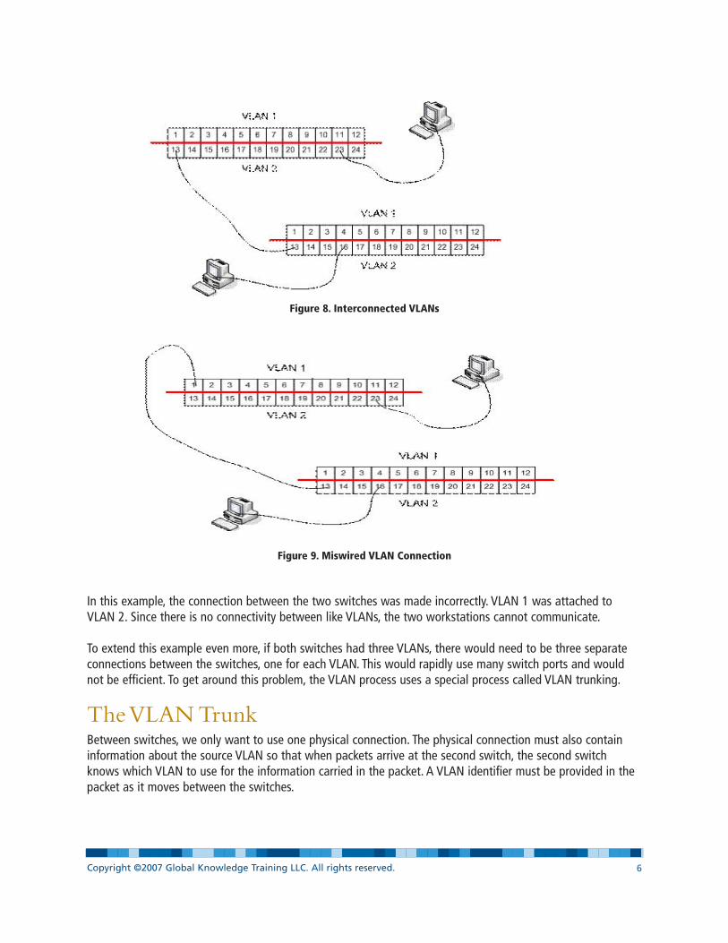
Figure 8. Interconnected VLANs
Figure 9. Miswired VLAN Connection
In this example, the connection between the two switches was made incorrectly. VLAN 1 was attached toVLAN 2. Since there is no connectivity between like VLANs, the two workstations cannot communicate.
To extend this example even more, if both switches had three VLANs, there would need to be three separateconnections between the switches, one for each VLAN. This would rapidly use many switch ports and wouldnot be efficient. To get around this problem, the VLAN process uses a special process called VLAN trunking.
The VLAN TrunkBetween switches, we only want to use one physical connection. The physical connection must also containinformation about the source VLAN so that when packets arrive at the second switch, the second switchknows which VLAN to use for the information carried in the packet. A VLAN identifier must be provided in thepacket as it moves between the switches.
Copyright ©2007 Global Knowledge Training LLC. All rights reserved. Page 6

Figure 10. Ethernet Header
An Ethernet packet has a header that contains three elements, the target address, the source address, and theprotocol type. There is no place in the header to contain a VLAN identification, and there are far too manypieces of Ethernet hardware that expects the normal format of the header to make an adjustment. The realityis that the only devices that really need to know about the VLAN identity are the switches and, occasionally,the routers.
To implement the VLAN identity in the switches, the standard calls for the definition of a special kind of switchport called the “trunk port.” The administrator of the switch designates one or more ports as trunk ports. Theseports may only be connected to trunk ports on other devices. Connecting a server or workstation to a trunkport will result in a failure to communicate. Connecting a trunk port to a neighboring switch port that is not adedicated trunk port will have similar results. The reason for the failure is that the Ethernet packets going overthe trunk ports have a different format.
802.1Q Trunking ProtocolThe IEEE 802.1Q trunking protocol allows for the modification of the Ethernet header. The header will nowinclude additional information that includes the VLAN identity of the packet being sent over the trunk.
Figure 11. Ethernet Headers w/wo 802.1Q Tag
Notice that the Protocol and Payload has shifted, and that the 802.1Q trunking protocol element or “tag” hasbeen inserted. Trunking ports on the switches use this information to determine the VLAN identity of the pack-et when it arrives at the switch. It is removed before the packet is sent to a workstation or server on the net-work since they will not be able to understand the modified packed.
Figure 12. 802.1Q Tag Format
The 802.1Q tag contains a protocol identifier that tells the switches that a tag is attached. Following that is anarea containing the VLAN ID and then a tag element that allows the switches to prioritize traffic from variousVLANs.
Using the TagThe tag allows the switches to identify traffic by VLAN of origination. That VLAN IDid also contains the VLANdestination on another switch.
Copyright ©2007 Global Knowledge Training LLC. All rights reserved. Page 7
Target Address Source Address Protocol Payload
Target Address Source Address Protocol Payload
Target Address Source Address 802 1Q Tag Protocol Payload
Protocol VLAN ID Priority

Figure 13. Trunking between switches
In the example above, ports 1 and 13 on the two switches have been converted to trunk ports. They carryinformation between the switches but include the 802.1Q tag indicating the VLAN information. Now, if theworkstation on port 16 wants to send information to the workstation on port 23 of the other switch, theswitches know the VLAN information, and the data is properly delivered. Regardless of the switch configura-tion and VLAN port assignments, the switches can accurately get the information from the source port to thedestination port on the correct VLAN.
This example shows two switches, but VLAN tagging and VLAN support can be done at the enterprise levelwith many switches. The key to success is VLAN tagging and trunking the tagged frames.
Why Use VLANsAside from security concerns, the VLAN provides the user with a number of other benefits. One of the first ben-efits is the reduction in the number of switches required in a network. The example of the accounting andmanufacturing departments required that both departments be isolated from each other. Without the ability tocreate a virtual LAN in the single switch, the company would need to purchase two switches to perform thesame task, one switch for accounting and one for manufacturing. If we expand the picture to include a largenumber of departments, the reduction in the number of switches could be substantial and represent a largecost savings.
Figure 14. VLAN Table
Copyright ©2007 Global Knowledge Training LLC. All rights reserved. Page 8
Department Switch Ports Needed VLANAccounting 12 1Manufacturing 22 2Personnel 6 3Shipping & Receiving 3 4Information Technology 9 5Executive Suite 4 6Inventory Control 11 7

This small business has seven separate departments. If each were to be isolated on departmental switches,seven switches would need to be purchased. If all of the ports were combined on a larger switch, a 96- portswitch could be procured and seven separate VLANs created. Rather than administering seven different switch-es, the network personnel would only need to configure and maintain one switch. In the example below, VLANmembership is shown by the color indicated in block representing each port in the 96 port switch. All ports notassigned to VLANs 2 through 7 are automatically assigned to VLAN 1.
96 Port SwitchFigure 15. Sample VLAN Assignments
A second benefit is the reduction in the amount of administrative overhead required to manage a multi-switchenvironment. In the previous example with seven different switches, to move a workstation from the account-ing department to the personnel department, administrators would have to change one or more cables in thepatch panel and on the switches. With a VLAN, a port is assigned to a VLAN in the switch configuration.Moving a workstation between VLANs is as simple as changing the port VLAN assignment in the switch con-figuration. No cables are moved, only a software configuration change is needed. In the example below, thedevice plugged into port 5 has been moved to VLAN 5 and the device plugged into port 8 has been moved toVLAN 4. No cables were moved to change the assignment.
96 Port SwitchFigure 16. VLAN Assignment Modifications
A third benefit is physical location independence. Again, consider the seven- department model discussed earli-er. As the organization expanded, the departments moved into two separate buildings. Accounting, Personnel,IT and the Executive Suite were in one Building A and Manufacturing, Shipping and Receiving and InventoryControl moved into a Building B. To support the two buildings, a second switch was procured, and a trunk was
Copyright ©2007 Global Knowledge Training LLC. All rights reserved. Page 9
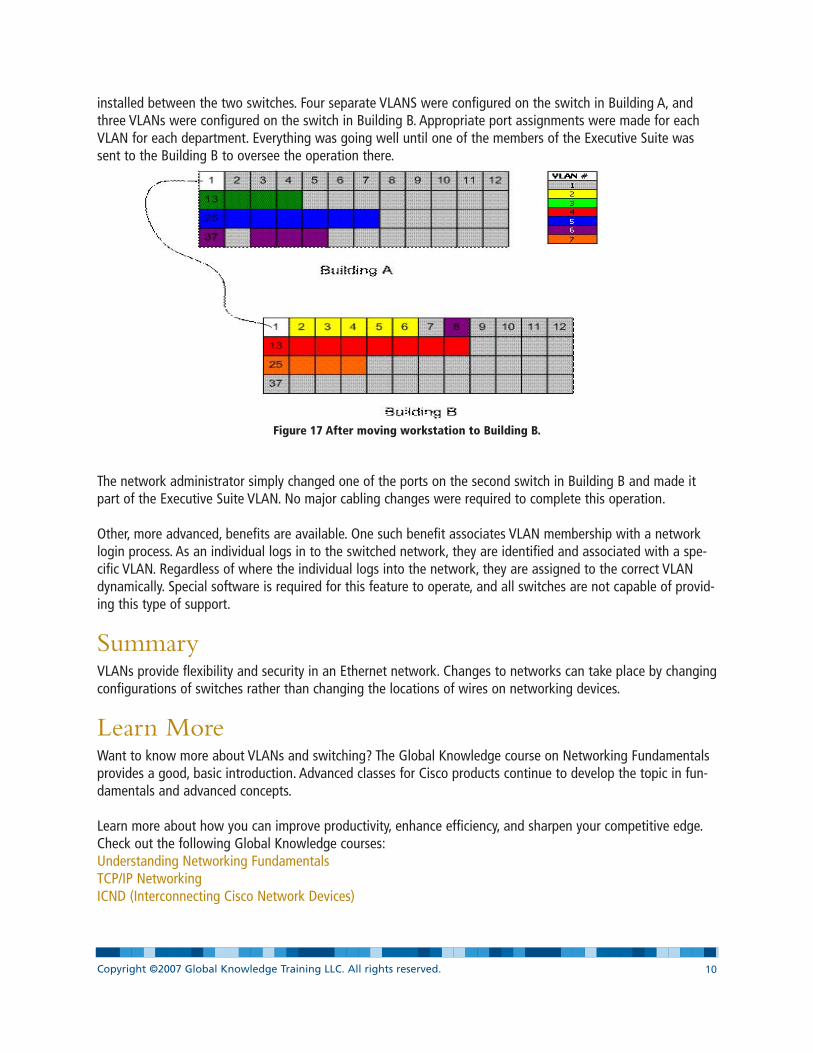
installed between the two switches. Four separate VLANS were configured on the switch in Building A, andthree VLANs were configured on the switch in Building B. Appropriate port assignments were made for eachVLAN for each department. Everything was going well until one of the members of the Executive Suite wassent to the Building B to oversee the operation there.
Figure 17 After moving workstation to Building B.
The network administrator simply changed one of the ports on the second switch in Building B and made itpart of the Executive Suite VLAN. No major cabling changes were required to complete this operation.
Other, more advanced, benefits are available. One such benefit associates VLAN membership with a networklogin process. As an individual logs in to the switched network, they are identified and associated with a spe-cific VLAN. Regardless of where the individual logs into the network, they are assigned to the correct VLANdynamically. Special software is required for this feature to operate, and all switches are not capable of provid-ing this type of support.
SummaryVLANs provide flexibility and security in an Ethernet network. Changes to networks can take place by changingconfigurations of switches rather than changing the locations of wires on networking devices.
Learn MoreWant to know more about VLANs and switching? The Global Knowledge course on Networking Fundamentalsprovides a good, basic introduction. Advanced classes for Cisco products continue to develop the topic in fun-damentals and advanced concepts.
Learn more about how you can improve productivity, enhance efficiency, and sharpen your competitive edge.Check out the following Global Knowledge courses:Understanding Networking FundamentalsTCP/IP NetworkingICND (Interconnecting Cisco Network Devices)
Copyright ©2007 Global Knowledge Training LLC. All rights reserved. Page 10
For more information or to register, visit www.globalknowledge.com or call 1-800-COURSES to speak with asales representative.
Our courses and enhanced, hands-on labs offer practical skills and tips that you can immediately put to use.Our expert instructors draw upon their experiences to help you understand key concepts and how to applythem to your specific work situation. Choose from our more than 700 courses, delivered through Classrooms,e-Learning, and On-site sessions, to meet your IT and management training needs.
About the AuthorTed Rohling has been a contract instructor with Global Knowledge since 1995. With over 40 years of experi-ence in information technology, telecommunications, and security, Ted teaches in the Networking and Securityproduct lines and focuses on TCP/IP, Networking Fundamentals, Network Management, Storage Networking,and CISSP Preparation. He currently holds the CISSP certification and has previously held various certificationsfrom Nortel, Cisco, and Microsoft. His educational background includes a BBA in Management Science, andMA in Information and Computer Management, and an MS in Educational Human Resource Development.
Copyright ©2007 Global Knowledge Training LLC. All rights reserved. Page 11