case study on applications of structural fuses in bridge bentsbruneau/asce 2016 wei and...
TRANSCRIPT

Case Study
Case Study on Applications of Structural Fuses inBridge Bents
XiaoneWei1 and Michel Bruneau, F.ASCE2
Abstract: In seismic design, bridges are typically designed to undergo inelastic deformations during a severe earthquake. In those instances,most of the seismic energy is dissipated through hysteretic behavior of the critical load-resisting components, which results in permanent sys-tem deformations and damage and could make repairs expensive or, in some cases, impossible. Thus, concentrating earthquake damage instructural fuses inserted in bridge bents is desirable; the performance objective is for the main gravity load-bearing members (the columns, inthis case) to be intact after an earthquake, limiting repairs to fuses that can be removed and replaced easily. This paper presents results fromcase studies that considered the use of buckling-restrained braces (BRBs) as hysteretic energy-dissipation devices inserted in bridge bents todissipate earthquake energy and improve structural performance by minimizing inelastic demands on the columns. A typical California bridgewas used for this purpose. For structural fuse application only in the transverse direction (along the bent), results indicate that BRBs are imple-mentable. Alternative bent configurations were also considered to provide the benefit of structural fuses for seismic excitations in the bridge’slongitudinal and transverse directions. Findings are presented along with observations from a comparison of seismic responses betweenbridges with and those without structural fuses in their bents. DOI: 10.1061/(ASCE)BE.1943-5592.0000854. © 2016 American Society ofCivil Engineers.
Author keywords: Buckling-restrained braces; Structural fuse; Seismic analysis; California bridges; Columns; Earthquake-resistantdesign.
Introduction
Seismic bridge design procedures still rely, to a large degree, on thedetailing of bridge columns for ductile response to provide lateralload resistance. Because columns are also part of the gravity load-resisting system, inelastic deformations in columns may compro-mise the stability of a bridge during an earthquake or result in per-manent damage that is beyond repair afterward. For well-detailedductile RC columns, prevention of the bridge’s total collapse can beachieved, but the seismic damage sustained can often require tem-porary closure of the bridge for days or even weeks to bring it backto service condition. From a postearthquake perspective, acceler-ated bridge construction (ABC) implies an ability to expedite bridgerepairs and, if possible, execute those repairs while keeping thebridge open or, at worst, limiting disturbance by requiring onlyshort-duration closures (typically by accomplishing work at night).Toward that objective, using structural fuses (SFs) is attractive,because they dissipate hysteretic energy in select structural ele-ments separate from the columns in such a way that the columns areleft intact and the fuses can be removed and replaced.In this paper, buckling-restrained braces (BRBs) are investigated
as SFs implemented in a typical California bridge (or types ofbridges that would be compatible with Caltrans practice). A
corresponding design procedure is proposed; concrete-filled steeltube (CFT) columns were used and BRBs were sized to meet the SFobjectives under the governing seismic lateral loads for two pro-posed bridge bent configurations. First, a two-column bent (consid-ering single-inclined BRB and inverted-V BRB configurations), forwhich response of the bent under seismic excitation in the transversedirection, was studied with the understanding that this implementa-tion of the fuse strategy would have to be coupled with another sys-tem in the longitudinal direction (which could be, e.g., SFs in serieswith lock-up devices connecting the bridge deck to the abutments).Second, a box-pier configuration was designed to allow for theimplementation of SFs to resist earthquake excitations in both longi-tudinal and transverse directions. Pushover analyses were performedto investigate seismic demands on the columns, and theoretical andactual pushover curves were compared. A seismic and service loaddemand check on the CFT columns was conducted. Results fromnonlinear time-history analyses of all the bridge bents with BRBs,subjected to spectrum-compatible synthetic groundmotions, are pre-sented and verified with the bridge bent displacements predictedfrom the design procedure. The displacement demands of the sys-tems with BRBs were also compared with those correspondingbridge bents without BRBs to quantify the benefit of adding BRBsinto the bridge bents. Note that the concept proposed here would beapplicable only when no traffic is permitted between the columnstied by the BRBs (unless horizontal and vertical clearances can beensured). Furthermore, the aesthetics of the proposed concept, whichmay be a concern to some, is beyond the scope of this paper and bestleft to individual DOTs and bridge owners to assess.Although BRBs have never been used in the SF application pre-
sented in this case study, BRBs have been used extensively in build-ings and are starting to be used more frequently in bridges. Initiallydeveloped in Japan in the mid-1980s (then referred to as unboundedbraces), BRBs have been implemented in North America since thelate 1990s. Although a variety of BRB concepts have been developed
1Graduate Research Assistant, Dept. of Civil, Structural, andEnvironmental Engineering, Univ. at Buffalo, Buffalo, NY 14260 (corre-sponding author). E-mail: [email protected]
2Professor, Dept. of Civil, Structural, and Environmental Engineering,Univ. at Buffalo, Buffalo, NY 14260. E-mail: [email protected]. This manuscript was submitted on December 18, 2014; approved
on September 14, 2015; published online on February 8, 2016.Discussion period open until July 8, 2016; separate discussions must besubmitted for individual papers. This paper is part of the Journal ofBridge Engineering, © ASCE, ISSN 1084-0702.
© ASCE 05016004-1 J. Bridge Eng.
J. Bridge Eng., 2016, 21(7): 05016004
yg
yy
()
pyg
py
g

and patented, a BRB generally consists of a central core surroundedby a tube that restrains the core fromaxial global buckling in compression.Extensive analytical and experimental research has been con-
ducted using BRBs to reduce the inelastic deformations of the existingbuilding frames (Wada et al. 2000; Aiken et al. 2000; Clark et al.2000; Lopez et al. 2002). Descriptions of the mechanics of BRBs withfully detailed design examples as BRB frames were presented byLópez and Sabelli (2004). Applications of BRBs in bridges wererecently contemplated and, in a few cases, implemented. Usami et al.(2005) studied the implementation of BRBs for the seismic upgradingof steel arch-truss bridges, such as the long-span Minato Bridge inJapan, which was retrofitted by installing BRBs on the cross frames ofthe main tower and on the lower lateral bracing near the main tower(Hamada et al. 2007). Also, Kanaji et al. (2005) reported that analysesof the retrofitted bridge proved that BRBswere effective in preventingbuckling or yielding of the other main members of the bridge. BRBswere also implemented in the seismic retrofit of a parabolic hauncheddeck-truss superstructure (the Auburn-Foresthill Road Bridge innorthern California) by replacing the horizontal chevron bracingmembers near the abutment and longitudinal struts with BRBs to con-trol loads in the critical load path system (Reno and Pohl 2010). Otherexample applications include the Araku-bashi Bridge, a rigid framebridge with a knee brace in which a new type of T-BRBs with steelmortar planks was used (Oya et al. 2009), and the Owatari Bridge, thefirst new arch-truss bridge built with BRBs to enhance its seismic per-formance. Another possible use of BRBs was studied for the VincentThomas suspension bridge in California to replace the viscous fluiddampers that are part of the existing seismic mitigation system(Lanning et al. 2011).Other promising applications of BRBs in bridges include new
bridge column configurations, such as the twin-column bridge stud-ied by El-Bahey and Bruneau (2010), and ductile end cross framesin slab-on-girder bridges, such as those studied by Carden et al.(2006) as an implementation of the ductile diaphragm conceptdeveloped by Zahrai and Bruneau (1999). Actual implementationof BRBs as a ductile cross-frame concept in a new bridge wasshown by Uang et al. (2014). Figures for the other bridge applica-tions of the BRBs mentioned here can be found inWei and Bruneau(2013) and Uang et al (2014).In contrast to these studies and implementations, for the case study
presented here, the authors considered the possible implementation ofBRBs in the conventional bents of standard highway bridges, as partof a SF concept, which has not been attempted before.
SFConcept
A SF system can be divided into two parts, namely, the frame that isintended to remain elastic (i.e., the bare bridge bent in this case) andthe SF that is the hysteretic energy-dissipating element. In a genericsense, the overall stiffness of the bridge bent, Ktot, is equal to thesum of the lateral stiffness, Ks, provided by the SF, and the lateralstiffness of the bare bridge bent,Kf . Correspondingly, a stiffness ra-tio, a, is defined as the ratio between Ks andKf such that
Ktot ¼ Kf þ Ks (1)
a ¼ Ks
Kf(2)
The system’s displacement ductility capacity, mD, which is themaximum ductility that the SF can develop before the bent columnyields, is defined as
mD ¼Dyf
Dys(3)
where Dys = displacement reached by the bridge bent when the SFyields; and Dyf = yield displacement of the corresponding barebridge bent.The most efficient use of SF is achieved when the difference
between bare bent and fuse yield displacement is maximized. Otheruseful nondimensional parameters related to the strength of the sys-tem include the seismic demand of the total system, Ve, if the sys-tem behaved elastically up to the corresponding expected displace-ment, d e; the yield strength of the bare bent, Vyf , which is the forceresisted by the bare bent when the yield displacement of the columnis reached; and the yield strength of the SF, Vys, which is the forceresisted by the fuse after the fuse yields. The maximum displace-ment ductility that the bridge bent needs to withstand is given by theductility ratio calculated at the system displacement reached for themaximum credible earthquake (expected displacement), d e. Whenthe expected displacement d e is in the constant-velocity region ofthe spectrum
d e ¼ Ve
Ktot(4)
For the SF system to be effective, the expected displacementd e should be larger than the yield displacement Dys that the bentreaches when the SF yields but smaller than the yield displace-ment Dyf that corresponds to yielding of the bent columns.Among all the parameters already defined, the ductility factor mDand the stiffness ratio a can be thought of as those that govern thedesign of the SFs for the system. The pushover force-displace-ment curves are shown in Fig. 1 for the bare bent, the SF, and thetotal SF system, with the displacement and force notation alreadydefined. More information on this SF concept is available else-where [e.g., Vargas and Bruneau (2006) and El-Bahey andBruneau (2010)].
Fig. 1. General pushover curve for the bridge bent system with struc-tural fuses
© ASCE 05016004-2 J. Bridge Eng.
J. Bridge Eng., 2016, 21(7): 05016004
yg
yy
yg
yg

Proposed Design Procedures
This case study focuses on the Caltrans generic bridge OrdinaryStandard Bridge 1 (OSB1), for which drawings were provided byCaltrans for this purpose. This two-span continuous bridge has atotal abutment-to-abutment length of 91.4 m (300 ft) and is sup-ported on an integral two-column bent at midspan (as shown in Fig. 2).Although the use of RC columns was considered in the early phasesof the study, the final designs were made with CFT columns,because it was found to facilitate the design of the SF system andconnection of BRBs to the columns.The flowchart in Fig. 3 summarizes the design procedure of the
proposed bridge bent with SFs, recognizing that the process wasiterative. Following that flowchart, the design procedure can be bro-ken down in the following steps.
Step 1: Calculations of the Bent Target Displacementand Bare Bent Stiffness
The maximum displacement permissible with the SF concept is setequal to the yield displacement of the column (also called theexpected displacement in subsequent steps), which can be calcu-lated when the stiffness of the bare bent is known. For preliminarydesign, to size a column’s diameter, the gravity dead load of thebridge’s superstructure tributary to the column bent was assumed tobe distributed equally to each column of the center bridge bent, anddead-load demand was taken to be approximately 5% of the overallaxial strength of each CFT column. Note that CFT columns have noreinforcement in the concrete infill and that their properties andstrengths (in particular, their cross-section axial compressive andtensile strength, flexural strength, and yielding curvature) wereobtained through fiber analysis using the program Section Designerin SAP2000 14. The buckling compressive strength of the columnwas checked using equations from AISC (2010) for compositemembers. The yield displacement, Dy, and the effective stiffness ofthe CFT column,Kcol, were calculated as
Dy ¼ 2w y
h2
� �23
(5)
Kcol ¼ 2My
hDy(6)
where w y = yield curvature of the CFT section; h = height of the CFTcolumn; andMy = yield strength of the CFT column. Note that OSB1has an integral bent with columns fixed at the top of the cap beam. Fora nonintegral bent, the bare bent stiffness would be smaller, and thestiffness of the BRB needed to achieve the SF design objective wouldbe different, but the designmethodology would remain the same.
Step 2: Calculation of Required Fuse Stiffness
The required fuse stiffness is selected to be the minimum valuerequired to prevent column yielding. For this purpose, the expected
Fig. 2. Caltrans OSB1: (a) elevation; (b) bridge bent at the center of the bridge span (Note: Unit = ft; OG = original ground; EOD = edge of deck;CIP = cast in place; PS = prestressed)
Fig. 3. Design flowchart of a bridge bent with BRBs
© ASCE 05016004-3 J. Bridge Eng.
J. Bridge Eng., 2016, 21(7): 05016004
yg
yy
()
pyg
py
g
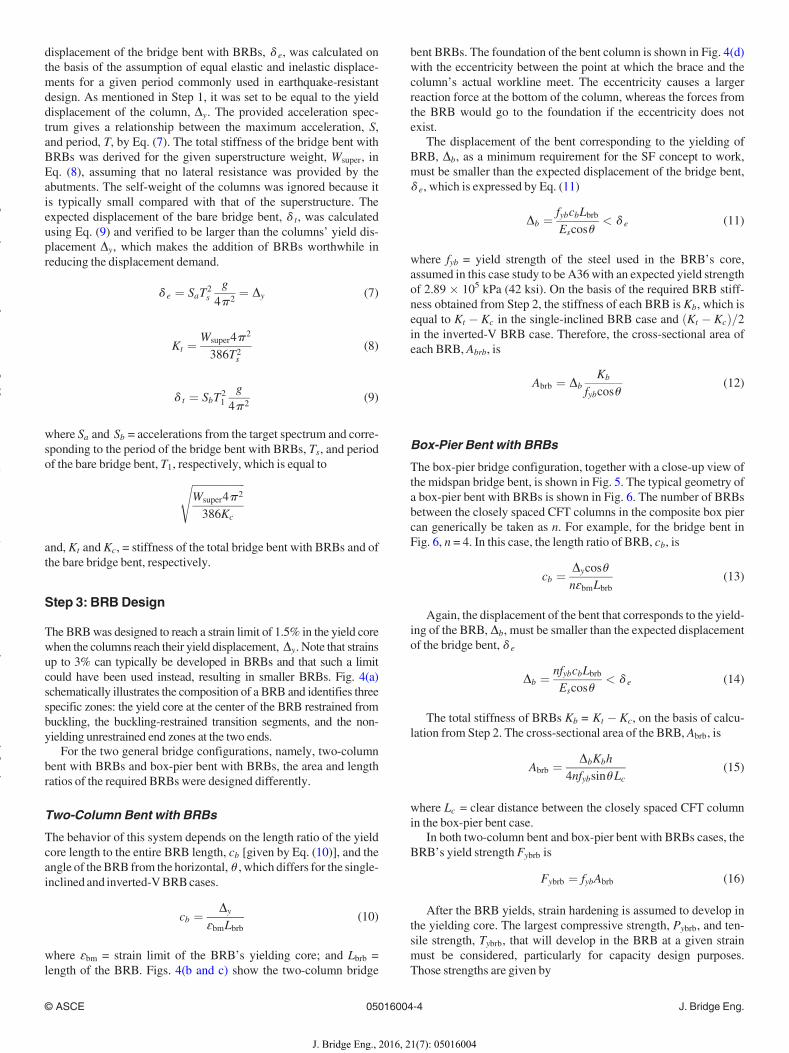
displacement of the bridge bent with BRBs, d e, was calculated onthe basis of the assumption of equal elastic and inelastic displace-ments for a given period commonly used in earthquake-resistantdesign. As mentioned in Step 1, it was set to be equal to the yielddisplacement of the column, Dy. The provided acceleration spec-trum gives a relationship between the maximum acceleration, S,and period, T, by Eq. (7). The total stiffness of the bridge bent withBRBs was derived for the given superstructure weight, Wsuper, inEq. (8), assuming that no lateral resistance was provided by theabutments. The self-weight of the columns was ignored because itis typically small compared with that of the superstructure. Theexpected displacement of the bare bridge bent, d t, was calculatedusing Eq. (9) and verified to be larger than the columns’ yield dis-placement Dy, which makes the addition of BRBs worthwhile inreducing the displacement demand.
d e ¼ SaT2s
g4p 2
¼ Dy (7)
Kt ¼ Wsuper4p 2
386T2s(8)
d t ¼ SbT21
g4p 2
(9)
where Sa and Sb = accelerations from the target spectrum and corre-sponding to the period of the bridge bent with BRBs, Ts, and periodof the bare bridge bent, T1, respectively, which is equal toffiffiffiffiffiffiffiffiffiffiffiffiffiffiffiffiffiffiffiffi
Wsuper4p 2
386Kc
s
and, Kt and Kc, = stiffness of the total bridge bent with BRBs and ofthe bare bridge bent, respectively.
Step 3: BRBDesign
The BRBwas designed to reach a strain limit of 1.5% in the yield corewhen the columns reach their yield displacement, Dy. Note that strainsup to 3% can typically be developed in BRBs and that such a limitcould have been used instead, resulting in smaller BRBs. Fig. 4(a)schematically illustrates the composition of a BRB and identifies threespecific zones: the yield core at the center of the BRB restrained frombuckling, the buckling-restrained transition segments, and the non-yielding unrestrained end zones at the two ends.For the two general bridge configurations, namely, two-column
bent with BRBs and box-pier bent with BRBs, the area and lengthratios of the required BRBs were designed differently.
Two-Column Bent with BRBs
The behavior of this system depends on the length ratio of the yieldcore length to the entire BRB length, cb [given by Eq. (10)], and theangle of theBRB from the horizontal, u , which differs for the single-inclined and inverted-VBRBcases.
cb ¼ Dy
ɛbmLbrb(10)
where ɛbm = strain limit of the BRB’s yielding core; and Lbrb =length of the BRB. Figs. 4(b and c) show the two-column bridge
bent BRBs. The foundation of the bent column is shown in Fig. 4(d)with the eccentricity between the point at which the brace and thecolumn’s actual workline meet. The eccentricity causes a largerreaction force at the bottom of the column, whereas the forces fromthe BRB would go to the foundation if the eccentricity does notexist.The displacement of the bent corresponding to the yielding of
BRB, Db, as a minimum requirement for the SF concept to work,must be smaller than the expected displacement of the bridge bent,d e, which is expressed by Eq. (11)
Db ¼ fybcbLbrbEscosu
< d e (11)
where fyb = yield strength of the steel used in the BRB’s core,assumed in this case study to be A36 with an expected yield strengthof 2.89 � 105 kPa (42 ksi). On the basis of the required BRB stiff-ness obtained from Step 2, the stiffness of each BRB is Kb, which isequal to Kt � Kc in the single-inclined BRB case and ðKt � KcÞ=2in the inverted-V BRB case. Therefore, the cross-sectional area ofeach BRB, Abrb, is
Abrb ¼ DbKb
fybcosu(12)
Box-Pier Bent with BRBs
The box-pier bridge configuration, together with a close-up view ofthe midspan bridge bent, is shown in Fig. 5. The typical geometry ofa box-pier bent with BRBs is shown in Fig. 6. The number of BRBsbetween the closely spaced CFT columns in the composite box piercan generically be taken as n. For example, for the bridge bent inFig. 6, n = 4. In this case, the length ratio of BRB, cb, is
cb ¼ DycosunɛbmLbrb
(13)
Again, the displacement of the bent that corresponds to the yield-ing of the BRB, Db, must be smaller than the expected displacementof the bridge bent, d e
Db ¼ nfybcbLbrbEscosu
< d e (14)
The total stiffness of BRBs Kb = Kt � Kc, on the basis of calcu-lation from Step 2. The cross-sectional area of the BRB, Abrb, is
Abrb ¼ DbKbh4nfybsinuLc
(15)
where Lc = clear distance between the closely spaced CFT columnin the box-pier bent case.In both two-column bent and box-pier bent with BRBs cases, the
BRB’s yield strength Fybrb is
Fybrb ¼ fybAbrb (16)
After the BRB yields, strain hardening is assumed to develop inthe yielding core. The largest compressive strength, Pybrb, and ten-sile strength, Tybrb, that will develop in the BRB at a given strainmust be considered, particularly for capacity design purposes.Those strengths are given by
© ASCE 05016004-4 J. Bridge Eng.
J. Bridge Eng., 2016, 21(7): 05016004
yg
yy
()
pyg
py
g

Fig. 4. (a) Typical steel section of a BRB; (b) transverse two-column bridge bent with BRBs, single inclined; (c) transverse two-column bridge bentwith BRBs, inverted V; (d) transverse two-column bridge bent with BRBs, single inclined with eccentricity
Fig. 5. Three-dimensional model of the bridge system with enlarged view of the bridge bents in the middle of the bridge without BRBs (with columnnumbering)
© ASCE 05016004-5 J. Bridge Eng.
J. Bridge Eng., 2016, 21(7): 05016004
yg
yy
()
pyg
py
g

Pybrb ¼ vb fybAbrb (17)
Tybrb ¼ v fybAbrb (18)
where b and v = strain-hardening factors, which vary with theBRB sizes and suppliers, and are assumed here to be b ¼ 1:11 andv ¼ 1:35 at 1.5% strain (López and Sabelli 2004).
Step 4: Column Capacity Check and Design Iteration
Once a tentative design has been reached, the column capacity atthe expected displacement, d e, must be checked to ensure that thecolumn axial, flexural, and shear strength are not exceeded, consid-ering both the seismic and service load demands (including theexpected yield forces coming from BRBs per capacity design prin-ciples). Design iterations continue until a column of satisfactorystrength is found.It was observed during the process of implementing SFs in
this bridge that the design of the bridge columns was governedby the seismic load cases. Therefore, results of analyses underload combinations of gravity dead and live load, and for windloads, performed for the designs considered, are not presentedhere. Further detailed information can be found in Wei andBruneau (2013).
Bent Pushover Analysis and ColumnCapacity Check
Pushover analyses of the bents was performed using the programSAP2000 to verify development of the SF concept. To maintain theactual clear distance between the face of adjacent CFT columns towhich the BRBs were added to the bent, the bridge bents were mod-eled by the bold lines shown in Figs. 4 and 5. The CFT columnswere fixed at the top to the cap beam and at the bottom to theground. The BRBs were pin connected to the columns. The capbeam was modeled as infinitely rigid relative to the columns bymaking the moment of inertia 1,000 times larger than that
corresponding to the chosen section of the cap beam. The CFT col-umn in the analytical model was built using the SAP2000 SectionDesigner. Concrete in the CFT columns had the same strength of2.76� 104 kPa (4 ksi) as in the cap beam; however, the concrete inthe columns was deemed to be confined. The steel shell of the CFTcolumn was A572 Grade 60 steel. The core of the BRB was A36steel with a yield strength of 2.89� 105 kPa (42 ksi), which reached4.34 � 105 kPa (42 ksi) and 3.91 � 105 kPa (42 ksi) at strains of1.5% in compression and tension, respectively.The columns were modeled in segments, with fiber P-M2-M3
hinges used at the two ends of each segment. Each fiber hingelength was 10% of the length of the member. A fiber P-M2-M3hinge was located in the middle of each BRB. However, becausemoments were released at the ends of the BRB (pin ends), the fiberP-M2-M3 hinge, equivalent to a fiber P hinge, was used only tomodel the nonlinear axial behavior (resulting in trilinear behavior).Kinematic strain hardening was used in the fiber hinge of BRB.Note that Rossi (2015) compared the behavior of single-story BRBframes and analyzed it considering both isotropic and kinematichardening, as well as smooth hysteretic curves versus bilinearcurves. The differences in results obtained when using the variousmodels were found to depend on the selected level of maximumductility demand. On the basis of the results presented in that paper,variations in the maximum displacement demands obtained usingthe various hysteretic models should be no greater than 20% for thehigh ductility demands of the BRBs used here, given that the peakground acceleration of the nine synthetic ground motions fell in therange of 0.7–1.0 g.The dead loads, applied on the cap beam as the point load at
which the webs of the box-girder are located, were used as a start-ing step of the nonlinear pushover analysis. The lateral load usedfor the pushover analysis consists of a horizontal load applied atthe center of the cap beam. The horizontal displacement of the capbeam was the monitored displacement used in the displacement-control method in the pushover analysis. P-delta or second-ordereffect was not considered.The elastic demand of the bridge model was obtained from a
simple response spectrum analysis to assess the displacement andforce demand of the bent. For consistency with results from time-history analyses presented later, the modified National EarthquakeHazards Reduction Program (NEHRP) response spectrum (BSSC2003) in Fig. 7(a) was used. For comparison, the solid line and dot-ted lines correspond to, respectively, the Caltrans design accelera-tion spectrum specified for OSB1 and the NEHRP 2003 targetdesign acceleration spectrum with design spectral accelerations ofSDs ¼ 2g, SD1 ¼ 0:6g. The force demand of the columns in thepushover analysis was checked at the target displacement d e, whichis the elastic displacement demand obtained from the response spec-trum analysis. The pushover curve of each analyzed bent was plot-ted and compared with the theoretical one developed from the SFconcept. Because of the page limit, only capacity check results forthe transverse bent with inverted-V BRBs and box-pier case and thepushover curve comparisons of the box pier in both directions arepresented here. Additional detailed information can be found inWei and Bruneau (2013).
Two-Column Bent with Inverted-V BRBs
The two-column bent with inverted-V BRB case had CFT columns of1,219.2 mm (48 in.) in diameter with a 31.7-mm (1.25-in.)-thick steelshell. The BRBs had a cross section of 1.1 � 104 mm2 (17.178 in.2)and a yield length ratio of 0.085.
Fig. 6. Box pier with BRBs in the (a) transverse and (b) longitudinaldirections, four BRBs between the closely spaced columns
© ASCE 05016004-6 J. Bridge Eng.
J. Bridge Eng., 2016, 21(7): 05016004
yg
yy
()
pyg
py
g
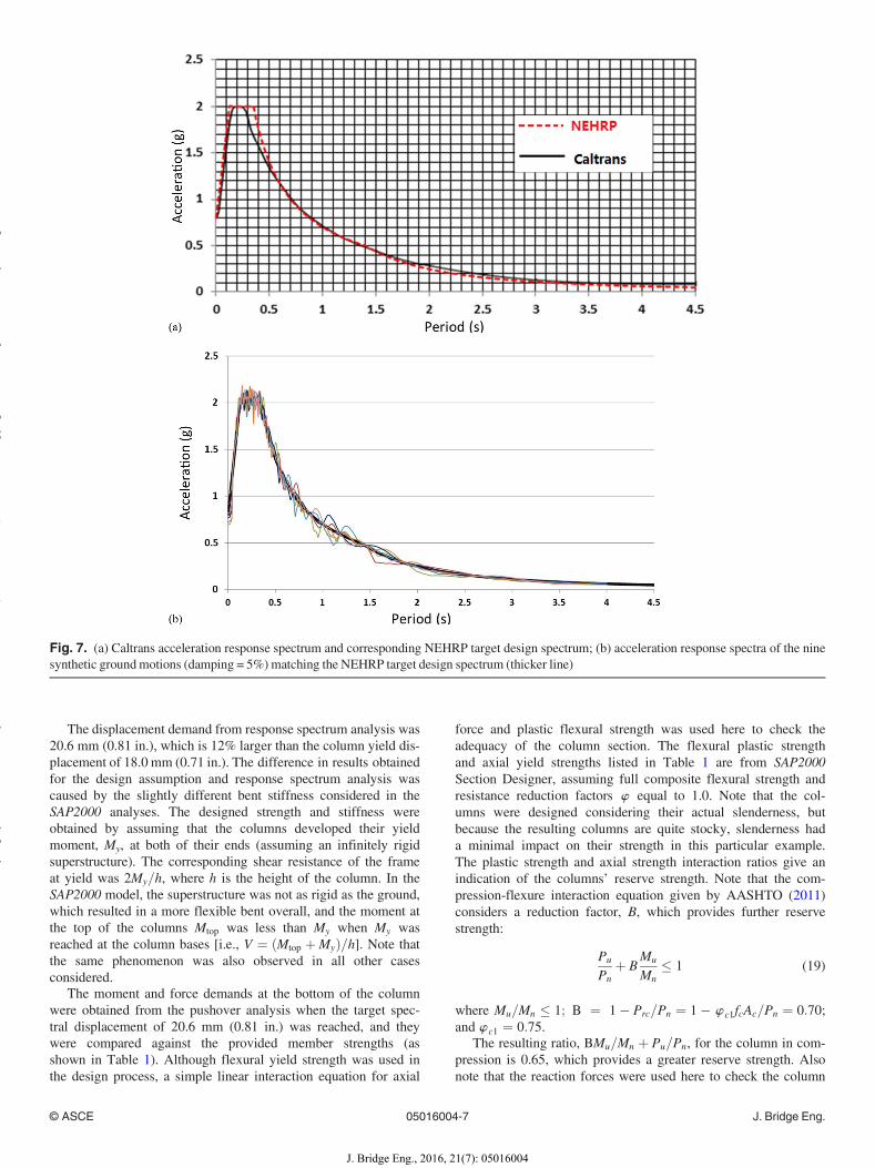
The displacement demand from response spectrum analysis was20.6 mm (0.81 in.), which is 12% larger than the column yield dis-placement of 18.0 mm (0.71 in.). The difference in results obtainedfor the design assumption and response spectrum analysis wascaused by the slightly different bent stiffness considered in theSAP2000 analyses. The designed strength and stiffness wereobtained by assuming that the columns developed their yieldmoment, My, at both of their ends (assuming an infinitely rigidsuperstructure). The corresponding shear resistance of the frameat yield was 2My=h, where h is the height of the column. In theSAP2000 model, the superstructure was not as rigid as the ground,which resulted in a more flexible bent overall, and the moment atthe top of the columns Mtop was less than My when My wasreached at the column bases [i.e., V ¼ ðMtop þMyÞ=h]. Note thatthe same phenomenon was also observed in all other casesconsidered.The moment and force demands at the bottom of the column
were obtained from the pushover analysis when the target spec-tral displacement of 20.6 mm (0.81 in.) was reached, and theywere compared against the provided member strengths (asshown in Table 1). Although flexural yield strength was used inthe design process, a simple linear interaction equation for axial
force and plastic flexural strength was used here to check theadequacy of the column section. The flexural plastic strengthand axial yield strengths listed in Table 1 are from SAP2000Section Designer, assuming full composite flexural strength andresistance reduction factors w equal to 1.0. Note that the col-umns were designed considering their actual slenderness, butbecause the resulting columns are quite stocky, slenderness hada minimal impact on their strength in this particular example.The plastic strength and axial strength interaction ratios give anindication of the columns’ reserve strength. Note that the com-pression-flexure interaction equation given by AASHTO (2011)considers a reduction factor, B, which provides further reservestrength:
Pu
Pnþ B
Mu
Mn� 1 (19)
where Mu=Mn � 1; B ¼ 1� Prc=Pn ¼ 1� w c1fcAc=Pn ¼ 0:70;and w c1 ¼ 0:75.The resulting ratio, BMu=Mn þ Pu=Pn, for the column in com-
pression is 0.65, which provides a greater reserve strength. Alsonote that the reaction forces were used here to check the column
Fig. 7. (a) Caltrans acceleration response spectrum and corresponding NEHRP target design spectrum; (b) acceleration response spectra of the ninesynthetic groundmotions (damping = 5%)matching the NEHRP target design spectrum (thicker line)
© ASCE 05016004-7 J. Bridge Eng.
J. Bridge Eng., 2016, 21(7): 05016004
yg
yy
()
pyg
py
g
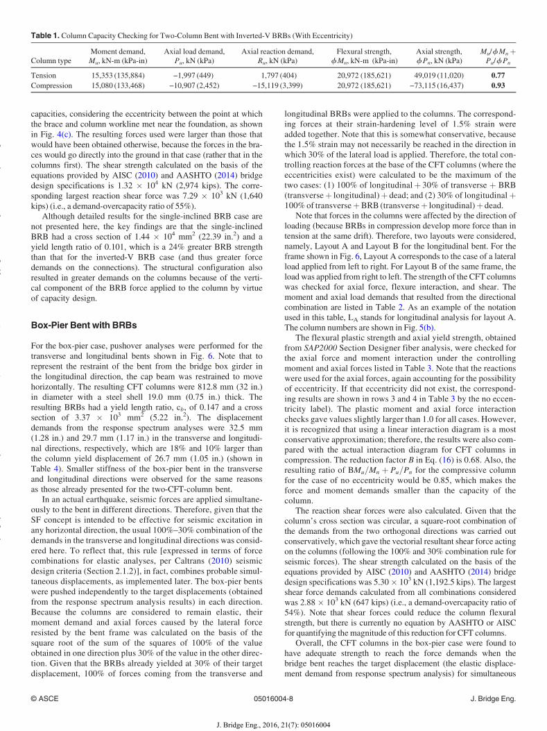
capacities, considering the eccentricity between the point at whichthe brace and column workline met near the foundation, as shownin Fig. 4(c). The resulting forces used were larger than those thatwould have been obtained otherwise, because the forces in the bra-ces would go directly into the ground in that case (rather that in thecolumns first). The shear strength calculated on the basis of theequations provided by AISC (2010) and AASHTO (2014) bridgedesign specifications is 1.32 � 104 kN (2,974 kips). The corre-sponding largest reaction shear force was 7.29 � 103 kN (1,640kips) (i.e., a demand-overcapacity ratio of 55%).Although detailed results for the single-inclined BRB case are
not presented here, the key findings are that the single-inclinedBRB had a cross section of 1.44 � 104 mm2 (22.39 in.2) and ayield length ratio of 0.101, which is a 24% greater BRB strengththan that for the inverted-V BRB case (and thus greater forcedemands on the connections). The structural configuration alsoresulted in greater demands on the columns because of the verti-cal component of the BRB force applied to the column by virtueof capacity design.
Box-Pier Bent with BRBs
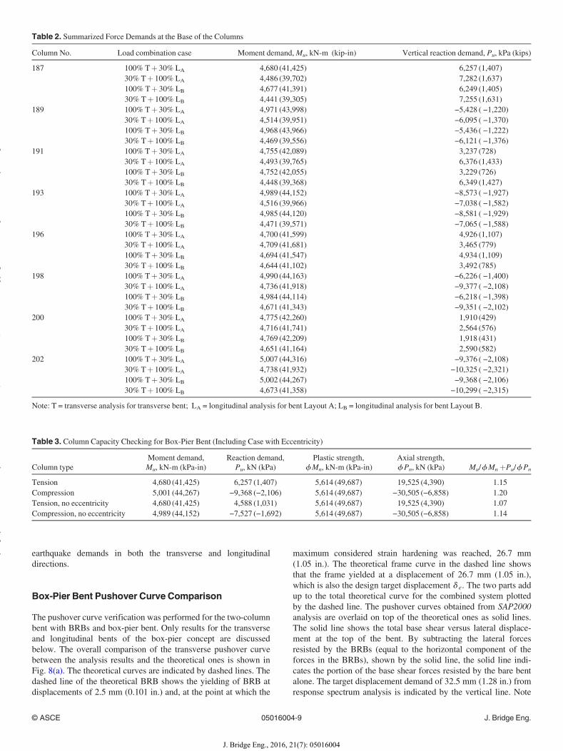
For the box-pier case, pushover analyses were performed for thetransverse and longitudinal bents shown in Fig. 6. Note that torepresent the restraint of the bent from the bridge box girder inthe longitudinal direction, the cap beam was restrained to movehorizontally. The resulting CFT columns were 812.8 mm (32 in.)in diameter with a steel shell 19.0 mm (0.75 in.) thick. Theresulting BRBs had a yield length ratio, cb, of 0.147 and a crosssection of 3.37 � 103 mm2 (5.22 in.2). The displacementdemands from the response spectrum analyses were 32.5 mm(1.28 in.) and 29.7 mm (1.17 in.) in the transverse and longitudi-nal directions, respectively, which are 18% and 10% larger thanthe column yield displacement of 26.7 mm (1.05 in.) (shown inTable 4). Smaller stiffness of the box-pier bent in the transverseand longitudinal directions were observed for the same reasonsas those already presented for the two-CFT-column bent.In an actual earthquake, seismic forces are applied simultane-
ously to the bent in different directions. Therefore, given that theSF concept is intended to be effective for seismic excitation inany horizontal direction, the usual 100%–30% combination of thedemands in the transverse and longitudinal directions was consid-ered here. To reflect that, this rule [expressed in terms of forcecombinations for elastic analyses, per Caltrans (2010) seismicdesign criteria (Section 2.1.2)], in fact, combines probable simul-taneous displacements, as implemented later. The box-pier bentswere pushed independently to the target displacements (obtainedfrom the response spectrum analysis results) in each direction.Because the columns are considered to remain elastic, theirmoment demand and axial forces caused by the lateral forceresisted by the bent frame was calculated on the basis of thesquare root of the sum of the squares of 100% of the valueobtained in one direction plus 30% of the value in the other direc-tion. Given that the BRBs already yielded at 30% of their targetdisplacement, 100% of forces coming from the transverse and
longitudinal BRBs were applied to the columns. The correspond-ing forces at their strain-hardening level of 1.5% strain wereadded together. Note that this is somewhat conservative, becausethe 1.5% strain may not necessarily be reached in the direction inwhich 30% of the lateral load is applied. Therefore, the total con-trolling reaction forces at the base of the CFT columns (where theeccentricities exist) were calculated to be the maximum of thetwo cases: (1) 100% of longitudinalþ 30% of transverse þ BRB(transverseþ longitudinal)þ dead; and (2) 30% of longitudinalþ100%of transverseþBRB (transverseþ longitudinal)þ dead.Note that forces in the columns were affected by the direction of
loading (because BRBs in compression develop more force than intension at the same drift). Therefore, two layouts were considered,namely, Layout A and Layout B for the longitudinal bent. For theframe shown in Fig. 6, Layout A corresponds to the case of a lateralload applied from left to right. For Layout B of the same frame, theload was applied from right to left. The strength of the CFT columnswas checked for axial force, flexure interaction, and shear. Themoment and axial load demands that resulted from the directionalcombination are listed in Table 2. As an example of the notationused in this table, LA stands for longitudinal analysis for layout A.The column numbers are shown in Fig. 5(b).The flexural plastic strength and axial yield strength, obtained
from SAP2000 Section Designer fiber analysis, were checked forthe axial force and moment interaction under the controllingmoment and axial forces listed in Table 3. Note that the reactionswere used for the axial forces, again accounting for the possibilityof eccentricity. If that eccentricity did not exist, the correspond-ing results are shown in rows 3 and 4 in Table 3 by the no eccen-tricity label). The plastic moment and axial force interactionchecks gave values slightly larger than 1.0 for all cases. However,it is recognized that using a linear interaction diagram is a mostconservative approximation; therefore, the results were also com-pared with the actual interaction diagram for CFT columns incompression. The reduction factor B in Eq. (16) is 0.68. Also, theresulting ratio of BMu=Mn þ Pu=Pn for the compressive columnfor the case of no eccentricity would be 0.85, which makes theforce and moment demands smaller than the capacity of thecolumn.The reaction shear forces were also calculated. Given that the
column’s cross section was circular, a square-root combination ofthe demands from the two orthogonal directions was carried outconservatively, which gave the vectorial resultant shear force actingon the columns (following the 100% and 30% combination rule forseismic forces). The shear strength calculated on the basis of theequations provided by AISC (2010) and AASHTO (2014) bridgedesign specifications was 5.30� 103 kN (1,192.5 kips). The largestshear force demands calculated from all combinations consideredwas 2.88 � 103 kN (647 kips) (i.e., a demand-overcapacity ratio of54%). Note that shear forces could reduce the column flexuralstrength, but there is currently no equation by AASHTO or AISCfor quantifying the magnitude of this reduction for CFT columns.Overall, the CFT columns in the box-pier case were found to
have adequate strength to reach the force demands when thebridge bent reaches the target displacement (the elastic displace-ment demand from response spectrum analysis) for simultaneous
Table 1. Column Capacity Checking for Two-Column Bent with Inverted-V BRBs (With Eccentricity)
Column typeMoment demand,Mu, kN-m (kPa-in)
Axial load demand,Pu, kN (kPa)
Axial reaction demand,Ru, kN (kPa)
Flexural strength,fMn, kN-m (kPa-in)
Axial strength,fPn, kN (kPa)
Mu/fMnþPu/fPn
Tension 15,353 (135,884) −1,997 (449) 1,797 (404) 20,972 (185,621) 49,019 (11,020) 0.77Compression 15,080 (133,468) −10,907 (2,452) −15,119 (3,399) 20,972 (185,621) −73,115 (16,437) 0.93
© ASCE 05016004-8 J. Bridge Eng.
J. Bridge Eng., 2016, 21(7): 05016004
yg
yy
()
pyg
py
g
earthquake demands in both the transverse and longitudinaldirections.
Box-Pier Bent Pushover Curve Comparison
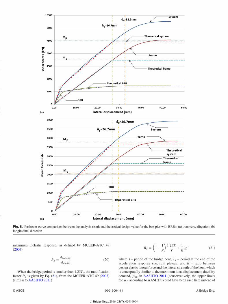
The pushover curve verification was performed for the two-columnbent with BRBs and box-pier bent. Only results for the transverseand longitudinal bents of the box-pier concept are discussedbelow. The overall comparison of the transverse pushover curvebetween the analysis results and the theoretical ones is shown inFig. 8(a). The theoretical curves are indicated by dashed lines. Thedashed line of the theoretical BRB shows the yielding of BRB atdisplacements of 2.5 mm (0.101 in.) and, at the point at which the
maximum considered strain hardening was reached, 26.7 mm(1.05 in.). The theoretical frame curve in the dashed line showsthat the frame yielded at a displacement of 26.7 mm (1.05 in.),which is also the design target displacement d e. The two parts addup to the total theoretical curve for the combined system plottedby the dashed line. The pushover curves obtained from SAP2000analysis are overlaid on top of the theoretical ones as solid lines.The solid line shows the total base shear versus lateral displace-ment at the top of the bent. By subtracting the lateral forcesresisted by the BRBs (equal to the horizontal component of theforces in the BRBs), shown by the solid line, the solid line indi-cates the portion of the base shear forces resisted by the bare bentalone. The target displacement demand of 32.5 mm (1.28 in.) fromresponse spectrum analysis is indicated by the vertical line. Note
Table 2. Summarized Force Demands at the Base of the Columns
Column No. Load combination case Moment demand,Mu, kN-m (kip-in) Vertical reaction demand, Pu, kPa (kips)
187 100% Tþ 30% LA 4,680 (41,425) 6,257 (1,407)30% Tþ 100% LA 4,486 (39,702) 7,282 (1,637)100% Tþ 30% LB 4,677 (41,391) 6,249 (1,405)30% Tþ 100% LB 4,441 (39,305) 7,255 (1,631)
189 100% Tþ 30% LA 4,971 (43,998) −5,428 ( −1,220)30% Tþ 100% LA 4,514 (39,951) −6,095 ( −1,370)100% Tþ 30% LB 4,968 (43,966) −5,436 ( −1,222)30% Tþ 100% LB 4,469 (39,556) −6,121 ( −1,376)
191 100% Tþ 30% LA 4,755 (42,089) 3,237 (728)30% Tþ 100% LA 4,493 (39,765) 6,376 (1,433)100% Tþ 30% LB 4,752 (42,055) 3,229 (726)30% Tþ 100% LB 4,448 (39,368) 6,349 (1,427)
193 100% Tþ 30% LA 4,989 (44,152) −8,573 ( −1,927)30% Tþ 100% LA 4,516 (39,966) −7,038 ( −1,582)100% Tþ 30% LB 4,985 (44,120) −8,581 ( −1,929)30% Tþ 100% LB 4,471 (39,571) −7,065 ( −1,588)
196 100% Tþ 30% LA 4,700 (41,599) 4,926 (1,107)30% Tþ 100% LA 4,709 (41,681) 3,465 (779)100% Tþ 30% LB 4,694 (41,547) 4,934 (1,109)30% Tþ 100% LB 4,644 (41,102) 3,492 (785)
198 100% Tþ 30% LA 4,990 (44,163) −6,226 ( −1,400)30% Tþ 100% LA 4,736 (41,918) −9,377 ( −2,108)100% Tþ 30% LB 4,984 (44,114) −6,218 ( −1,398)30% Tþ 100% LB 4,671 (41,343) −9,351 ( −2,102)
200 100% Tþ 30% LA 4,775 (42,260) 1,910 (429)30% Tþ 100% LA 4,716 (41,741) 2,564 (576)100% Tþ 30% LB 4,769 (42,209) 1,918 (431)30% Tþ 100% LB 4,651 (41,164) 2,590 (582)
202 100% Tþ 30% LA 5,007 (44,316) −9,376 ( −2,108)30% Tþ 100% LA 4,738 (41,932) −10,325 ( −2,321)100% Tþ 30% LB 5,002 (44,267) −9,368 ( −2,106)30% Tþ 100% LB 4,673 (41,358) −10,299 ( −2,315)
Note: T = transverse analysis for transverse bent; LA = longitudinal analysis for bent Layout A; LB = longitudinal analysis for bent Layout B.
Table 3. Column Capacity Checking for Box-Pier Bent (Including Case with Eccentricity)
Column typeMoment demand,Mu, kN-m (kPa-in)
Reaction demand,Pu, kN (kPa)
Plastic strength,fMn, kN-m (kPa-in)
Axial strength,fPn, kN (kPa) Mu/fMnþPu/fPn
Tension 4,680 (41,425) 6,257 (1,407) 5,614 (49,687) 19,525 (4,390) 1.15Compression 5,001 (44,267) −9,368 (−2,106) 5,614 (49,687) −30,505 (−6,858) 1.20Tension, no eccentricity 4,680 (41,425) 4,588 (1,031) 5,614 (49,687) 19,525 (4,390) 1.07Compression, no eccentricity 4,989 (44,152) −7,527 (−1,692) 5,614 (49,687) −30,505 (−6,858) 1.14
© ASCE 05016004-9 J. Bridge Eng.
J. Bridge Eng., 2016, 21(7): 05016004
yg
yy
()
pyg
py
g

that the theoretical bilinear curves were calculated on the basis ofthe flexural yield strength of the columns. The pushover curves ofthe bent models were obtained considering the axial force andmoment interaction in the column and strain hardening in the steeltubes. Beyond the yield displacement, the pushover curves of thebent models were higher than the theoretical ones.The overall comparison of the longitudinal bent’s pushover
curve between the analysis result and the theoretical ones is shownin a similar manner in Fig. 8(b), with the same solid- and dashed-line convention; the only difference is that the target elastic dis-placement demand from response spectrum analysis was 29.7 mm(1.17 in.) in this case.In both cases, the pushover analysis results indicate that column
yielding was first reached at the bottom of the column, where thetension and flexure interaction exists. The lower horizontal dottedline identifies the base shear resisted by the columns when that hap-pened. The upper dotted line shows the frame shear, V, correspond-ing to 2Mp=hcolumn calculated with Mp equal to 49,687 kip-in. (asobtained from SAP2000 Section Designer). Note that yielding in allcolumns as not happening at the same time, but it occurred oversmall increases of frame drift. If anything, Fig. 8 shows that limitingthe column demands to My, to prevent any column yielding, wasconservative. The use of a more liberal design limit is arguablypossible.
Nonlinear Time-History Analysis
To validate the system responses previously obtained for thebridge bents using response spectrum and pushover analyses,nonlinear time-history analyses of all the previously designedbridge bents with BRBs were performed by using SAP2000. Thenonlinear time-history analysis results enable assessment of theeffectiveness of adding the SF to limit displacements by compar-ing them with those for the bare bridge bents without BRBs. Notethat the bare bent case for the box-pier configuration is purelyacademic, because the box-pier system would never be used with-out BRBs.The computer program Target Acceleration Spectra Compatible
Time Histories (TARSCTHS) was used to generate nine spectrum-compatible synthetic ground motions with a time length of 25 s.That program is set up to match ground motions to the NEHRPdesign spectrum (BSSC 2003) as a target. In Fig. 7(b), the accelera-tion spectra of the nine ground motions are shown to match with thetarget response spectrum.
The nonlinear time-history analysis was performed for thetwo-dimensional (2D) bridge bent instead of the entire three-dimensional bridge, separately for the transverse and longitudinaldirections. Results of the 2D bent analysis make it easier to com-pare with the pushover analysis results for the same bent. Out-of-plane displacements of the bent were restrained. The mass of thebridge was assigned as a linearly distributed mass on the capbeam. The self-weight of the assigned mass was not accountedfor in the dead load because the mass was used only to apply thelateral seismic load to the bridge bent under the ground motions.The dead load was applied directly to the column before nonlineartime-history analysis was conducted. Hinge properties and assign-ments were defined the same way as was done for the pushoveranalyses. From the modal analysis, the mass participating ratiowas more than 90% for the first two modes. Rayleigh dampingwas used, with coefficients corresponding to 5% damping for thefirst and second modal periods.The averages of the maximum displacements in positive and neg-
ative in-plane transverse directions of the two-CFT-column bentsand the box-pier bents, with and without BRBs, that resulted fromthe nine groundmotions are shown in Table 4. The displacement his-tories of the bridge bents subjected to the ground motions can befound inWei and Bruneau (2013). Results show that in all cases, dis-placements of the bents with BRBs had average maximum absolutelateral displacements of less than 50% of the values for cases withoutBRBs. Residual displacements of the bents with BRBs were gener-ally less than 15% of the maximum displacements listed in Table 4;for comparison, this value was as high as 40% for the case withoutthe BRBs. This result is because the columns remained predomi-nantly elastic in the case with BRBs, thus helping provide recenter-ing (although it was not a perfect recentering). The design displace-ments and the elastic displacement demands from responsespectrum analyses are also shown for comparison. Note that both thedesign displacement and displacement demands from the responseanalyses of the bare bent were larger than those of the bent withBRB cases because of less lateral stiffness and a larger period.It is shown in Table 4 that the inelastic displacement demands
of the bridge bents were larger than the elastic response spectrumdemand because that design was based on the equal displacementassumption (i.e., assuming that displacements that result frominelastic analysis are approximately equal to those obtained froma linear elastic analysis). This is usually a reasonable assumption,except for short-period structures for which it is not conservative(AASHTO 2011). Recognizing this exception, a modificationfactor Rd is typically prescribed to magnify the maximum elasticdisplacements of short-period structures and estimate the actual
Table 4. Displacement of Bare Bent and Bent with BRBs for Different Systems in Theoretical Design, Response Spectrum Analysis, and Nonlinear Time-History Analysis
Case
Design target displacement Response spectrum analysis Nonlinear time history
Bare bent,mm (in.)
Bent withBRBs,mm (in.)
Difference(%)
Bare bentmm (in.)
Bent withBRBs,mm (in)
Difference(%)
Bare bent,mm (in.)
Bent withBRBs,mm (in.)
Difference(%)
Two-CFT-column bentwith single-inclinedBRB
58.4 (2.30) 18.0 (0.71) 69.2 71.4 (2.81) 23.9 (0.94) 66.6 54.4 (2.14) 28.7 (1.13) 47.2
Two-CFT-column bentwith inverted-V BRBs
58.4 (2.30) 18.0 (0.71) 69.2 71.4 (2.81) 20.6 (0.81) 71.2 54.4 (2.14) 27.9 (1.10) 48.8
Transverse box-pier bent 72.4 (2.85) 26.7 (1.05) 63.2 79.5 (3.13) 32.5 (1.28) 59.1 66.5 (2.62) 33.5 (1.32) 49.7Longitudinal box-pierbent
72.4 (2.85) 26.7 (1.05) 63.2 77.7 (3.06) 29.7 (1.17) 61.8 63.8 (2.51) 32.0 (1.26) 49.7
© ASCE 05016004-10 J. Bridge Eng.
J. Bridge Eng., 2016, 21(7): 05016004
yg
yy
()
pyg
py
g
maximum inelastic response, as defined by MCEER-ATC 49(2003)
Rd ¼ DinelasticDelastic
(20)
When the bridge period is smaller than 1.25Ts, the modificationfactor Rd is given by Eq. (21), from the MCEER-ATC 49 (2003)(similar to AASHTO 2011)
Rd ¼ 1� 1R
� �1:25Ts
Tþ 1R� 1 (21)
where T= period of the bridge bent; Ts = period at the end of theacceleration response spectrum plateau; and R = ratio betweendesign elastic lateral force and the lateral strength of the bent, whichis conceptually similar to the maximum local displacement ductilitydemand, mD, in AASHTO 2011 (conservatively, the upper limitsfor mD according to AASHTO could have been used here instead of
Fig. 8. Pushover-curve comparison between the analysis result and theoretical design value for the box pier with BRBs: (a) transverse direction; (b)longitudinal direction
© ASCE 05016004-11 J. Bridge Eng.
J. Bridge Eng., 2016, 21(7): 05016004
yg
yy
()
pyg
py
g
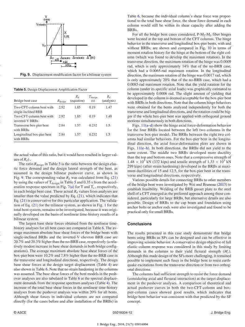
the actual value of this ratio, but it would have resulted in larger val-ues of Rd) .The ratio Rdesign in Table 5 is the ratio between the design elas-
tic force demand and the design lateral strength of the bent, asassumed in the design bilinear pushover curve, as shown inFig. 9. The corresponding value Rd was calculated from Eq. (21)by using the values of Tdesign in Table 5 and 0.35 s from the accel-eration response spectrum in Fig. 7(a) for T and Ts , respectively,in each bridge bent case. These actual Rd values from analyses aresmaller than the value predicted by Eq. (21), which indicates thatEq. (21) is conservative for this particular application. The valida-tion of Eq. (21) for the trilinear system, as shown in Fig. 1 for thetotal bent system, remains to be investigated, because it was origi-nally developed on the basis of nonlinear time-history results of abilinear system.The largest base shear forces obtained from the nonlinear time-
history analyses for all bent cases are compared in Table 6. The av-erage maximum absolute base shear forces of the bridge bents withsingle-inclined BRBs and the inverted-V chevron BRB case are20.7% and 20.3% higher than the no-BRB case, respectively (a rela-tively modest increase in base shear demands in both bridge config-urations). The average maximum absolute base shear forces of thebox-pier bent were 10.2% and 7.8% higher than the no-BRB case inthe transverse and longitudinal directions, respectively. The designbase shear forces at the design target displacement (Table 4) arealso shown in Table 6. Note that no strain hardening in the columnswas assumed. The base shear forces of the bent models in the push-over analyses are also tabulated in Table 6 at the spectral displace-ment demands from the response spectrum analyses (Table 4). Theincrease of the total base shear forces in the nonlinear time-historyanalyses from the pushover analysis was within 20% for all bents.Although shear forces in individual columns are not compareddirectly (for the cases before and after installation of the BRBs) in
Table 6, because the individual column’s shear force was propor-tional to the total base shear force, the shear force demand in eachcolumn would still be within its shear capacity after adding theBRBs.For all the bridge bent cases considered, P-M2-M3 fiber hinges
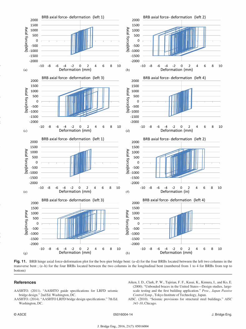
were located at the top and bottom of the CFT columns. The hingebehavior in the transverse and longitudinal box-pier bents, with andwithout BRBs, are shown and compared in Fig. 10 in terms ofmoment rotation history for the hinge at the bottom of the right col-umn (which was found to develop the maximum rotation). In thetransverse direction, the maximum rotation of the hinge was 0.0009rad, which is only approximately 14% that of the no-BRB case,which had a 0.0065-rad maximum rotation. In the longitudinaldirection, the maximum rotation of the hinge was 0.0017 rad, whichis only approximately 20% that of the no-BRB case, which had a0.0085-rad maximum rotation. Note that the yield rotation for thecolumn (under its specific axial loads) was graphically estimated tobe approximately 0.0006 rad. The slight amount of yielding thatdeveloped in the column is deemed acceptable for the box-pier bentwith BRBs in both directions. Note that the column hinge behaviorswere obtained for the bents analyzed independently for both thetransverse and longitudinal directions, and the rotation could be big-ger if the whole box-pier bent was applied with orthogonal groundmotions simultaneously in both directions.Figs. 11(a–d) show the hinge axial force-deformation behavior
for the four BRBs located between the left two columns in thetransverse box-pier model. The BRBs between the right two col-umns had similar behaviors. For the box-pier bent in the longitu-dinal direction, the axial force-deformation plots are shown inFigs. 11(e–h). In both directions, the BRBs did not yield to thesame extent. The middle two BRBs developed more ductilitythan the top and bottom ones. Note that a compressive strength of1.48 � 103 kN (332 kips) and tensile strength of 1.33 � 103 kN299 kips) (after strain hardening) developed in the BRBs at maxi-mum ductilities of 15 and 12.5, for the box-pier bent in the trans-verse and longitudinal directions, respectively.Various possible details for connecting BRBs to other members
of the bridge bent were investigated by Wei and Bruneau (2013) toestablish feasibility. Welding of the BRB gusset plate to the steelshell of a CFT emerged as the preferred approach among those con-sidered, particularly for large BRBs, but alternative details are alsopossible. Design of BRBs to the cap beam and foundation usinganchor bolts or anchor rods were also investigated and found to bepractical only for small BRBs.
Conclusions
The results presented in this case study demonstrate that bridgebents using BRBs as SFs can be designed and can be effective inimproving seismic behavior. A conservative design objective of fullelastic column response was considered in this study by limitingdemands in the columns to their yield flexural strength (My).Although this made design of the SFsmore challenging, it remainedpossible to implement such fuses in the bridge bent to resist earth-quake excitations from the transverse direction or from two orthog-onal directions.The columns had sufficient strength to resist the force demand
(considering axial and flexural interaction) at the target displace-ment in the pushover analyses. A comparison of theoretical andactual pushover curves in both the two-CFT-column and box-pier-column cases showed good results, which indicates thatbridge bent behavior was consistent with that predicted by the SFconcept.
Fig. 9. Displacement modification factor for a bilinear system
Table 5. Design Displacement Amplification Factor
Bridge bent case RdesignRd
(equation)Tdesign(s)
Rd
(analysis)
Two-CFT-column bent withsingle-inclined BRB
2.92 1.85 0.19 1.47
Two-CFT-column bent withinverted-V BRBs
2.92 1.85 0.19 1.49
Transverse box-pier bentwith BRBs
2.84 1.57 0.232 1.5
Longitudinal box-pier bentwith BRBs
2.84 1.57 0.232 1.5
© ASCE 05016004-12 J. Bridge Eng.
J. Bridge Eng., 2016, 21(7): 05016004
yg
yy
()
pyg
py
g

Nonlinear time-history analysis was also performed to verify thebehavior of the bridge bents compared to the responses predicted bythe design procedure, elastic response spectrum, and pushover anal-ysis. Displacement at the bent cap beam level and base shear forcedemand were compared for the bridge bents with BRBs in eachcase with their corresponding bare bent. For all the bents designedwith BRBs, drift reductions of at least 50% were accompanied bymodest increases in base shear demands no greater than 20%. Theinelastic displacement demands of the bridge bent model werefound to slightly exceed predictions based on the elastic displace-ments from the response spectrum analyses, which was a conse-quence of using a constant strength-reduction factor as part of thedesign procedure (which is known to result in greater inelastic dis-placement for structures that have short periods).
Although this case study shows concept feasibility, muchresearch is needed to optimize SF design parameters, enhance accu-racy of response predictions, and establish bounds within whicheffective solutions are possible.
Acknowledgments
This study was sponsored by Caltrans under research ContractNumber 65A0432. The authors acknowledge the valuablecomments and feedback from Caltrans. However, any opinions,findings, conclusions, and recommendations presented in thisreport are those of the writers and do not necessarily reflect theviews of the sponsor.
Table 6. Base Shear Force of Bare Bent and Bent with BRBs for Different Systems in Theoretical Design Calculation, Pushover Analyses, and NonlinearTime-history Analysis
Case
Design calculation Pushover Nonlinear time history
Bare bent,kN (kips)
Bent withBRBs, kN(kips)
Difference(%)
Bare bent,kN (kips)
Bent withBRBs, kN(kips)
Difference(%)
Bare bent,kN (kips)
Bent withBRBs, kN(kips)
Difference(%)
Two-CFT-column bentwith single-inclinedBRB
9,648 (2,169) 13,318 (2,994) 38 14,136 (3,178) 16,014 (3,600) 13.3 14,439 (3,246) 17,424 (3,917) 20.7
Two-CFT-column bentwith inverted-V BRBs
9,648 (2,169) 13,296 (2,989) 38 14,123 (3,175) 14,492 (3,258) 2.6 14,439 (3,246) 17,370 (3,905) 20.3
Transverse box-pier bent 5,200 (1,169) 7,357 (1,654) 41 7,602 (1,709) 8,438 (1,897) 11 7,789 (1,751) 8,585 (1,930) 10.2Longitudinal box-pierbent
2,602 (585) 3,679 (827) 41 3,843 (864) 4,012 (902) 4.4 3,923 (882) 4,230 (951) 7.8
Fig. 10. Hinge behaviors at bottom of the rightmost column of the box-pier bent (a) transverse with BRB, (b) longitudinal with BRB, (c) transverseno BRB, and (d) longitudinal no BRB
© ASCE 05016004-13 J. Bridge Eng.
J. Bridge Eng., 2016, 21(7): 05016004
yg
yy
()
pyg
py
g
References
AASHTO. (2011). “AASHTO guide specifications for LRFD seismicbridge design.” 2nd Ed.Washington, DC.
AASHTO. (2014). “AASHTO LRFD bridge design specifications.” 7th Ed.Washington, DC.
Aiken, I. D., Clark, P. W., Tajirian, F. F., Kasai, K., Kimura, I., and Ko, E.(2000). “Unbonded braces in the United States—Design studies, large-scale testing and the first building application.” Proc., Japan PassiveControl Symp., Tokyo Institute of Technology, Japan.
AISC. (2010). “Seismic provisions for structural steel buildings.” AISC341-10, Chicago.
Fig. 11. BRB hinge axial force-deformation plot for the box-pier bridge bent: (a–d) for the four BRBs located between the left two columns in thetransverse bent ; (e–h) for the four BRBs located between the two columns in the longitudinal bent (numbered from 1 to 4 for BRBs from top tobottom)
© ASCE 05016004-14 J. Bridge Eng.
J. Bridge Eng., 2016, 21(7): 05016004
yg
yy
()
pyg
py
g
BSSC (Building Seismic Safety Council). (2003). NEHRP recommendedprovisions and commentary for seismic regulations for new buildingsand other structures (FEMA 450), Washington, DC.
Caltrans (California Department of Transportation). (2010). “Caltrans seis-mic design criteria.”Version 1.6, Sacramento, CA.
Carden, L., Itani, A. P. E., and Buckle, F. I. (2006). “Seismic performance ofsteel girder bridges with ductile cross frames using buckling-restrainedbraces.” J. Struct. Eng., 10.1061/(ASCE)0733-9445(2006)132:3(338),338–345.
Clark, P., Aiken, I., Kasai, K., and Kimura, I. (2000). “Large-scale testingof steel unbonded braces for energy dissipation.” Adv. Technol. Struct.Eng., 1–5.
El-Bahey, S., and Bruneau, M., (2010). “Analytical development and exper-imental validation of a structural-fuse bridge pier concept.” Tech. Rep.MCEER-10-0005, MCEER, Univ. at Buffalo, Buffalo, NY.
Hamada, N., Nishioka, T., and Kanaji, H. (2007). “Seismic retrofitting oflong-span truss bridge-Minato Bridge using damage-control technolo-gies.” Steel Constr. Today Tomorrow, 19, 12–16.
Kanaji, H., Kitazawa, M., and Suzuki, N. (2005). “Seismic retrofit strategyusing damage control design concept and the response reduction effectfor a long-span truss bridge.” Proc., 19th US-Japan Bridge Eng.Workshop: UJNR Panel on Wind and Seismic Effects, United States/Japan Natural Resources Development Program, Tsukuba, Japan.
Lanning, J., Benzoni, G., and Uang, C. M. (2011) “The feasibility of usingbuckling-restrained braces for long-span bridges, a case study.” Tech.Rep. CA12-2149, Caltrans, Sacramento, CA.
Lopez, W., Gwie, D., Saunders, M., and Lauck, T. (2002) “Lessons learnedfrom large-scale tests of unbonded braced frame subassemblage.” Proc.,71st Annual Convention, Structural Engineers Association ofCalifornia, Sacramento, CA, 171–183.
López, W. A., and Sabelli, R. (2004). “Steel tips report: Seismic design ofbuckling-restrained braced frames.” Structural Steel EducationalCouncil, Lafayette, CA.
MCEER-ATC 49 (2003). “Recommended LRFD guidelines for the seismicdesign of highway bridges.” Tech. Rep. MCEER-03-SP03, MCEER,Univ. at Buffalo, Buffalo, NY.
Oya, T., Fukasawa, T., Fujiwara, M., et al. (2009). “Practical study on anew type buckling-retrained-brace.” Proc., Int. Association for Shelland Spatial Structure (IASS) Symp., Editorial Universitat Politècnica deValència, València, Spain.
Reno,M. L., and Pohl, M. N. (2010). “Seismic retrofit of California’s Auburn-Foresthill Bridge.” Transportation Research Record, 2201/2010, 83–94.
Rossi, P. (2015). “Importance of isotropic hardening in the modeling ofbuckling restrained braces.” J. Struct. Eng., 10.1061/(ASCE)ST.1943-541X.0001031, 04014124.
SAP2000 14 [Computer software]. Computers & Structures, Inc., WalnutCreek, CA.
TARSCTHS (Target Acceleration Spectra Compatible Time Histories)[Computer software]. Version 1, Univ. at Buffalo, Buffalo, NY.
Uang, C. M., Bruneau, M. K., and Tsai, C. (2014). “Seismic design of steelbridges” The CRC handbook of bridge engineering—Seismic design,CRC Press, Boca Raton, FL, 301–336.
Usami, T., Lu, Z., and Ge, H. (2005). “A seismic upgrading method for steelarch bridges using buckling-restrained braces.” Earthquake Eng. Struct.Dyn., 34(4–5), 471–496.
Vargas, R., and Bruneau, M. (2006). “Experimental investigation of thestructural fuse concept.” Tech. Rep. MCEER-06-0005, MCEER, Univ.at Buffalo, Buffalo, NY.
Wada, A., Huang, Y. H., and Iwata, M. (2000). “Passive damping technol-ogy for buildings in Japan.” Prog. Struct. Mater. Eng., 2(3), 335–350.
Wei, X., and Bruneau, M. (2013). “Resilient bridges: Replaceable structuralfuses for post-earthquake accelerated service, phase1:Analytical investi-gation,”Tech.Rep.CA13-2296, Caltrans, Sacramento,CA.
Zahrai, S. M., and Bruneau, M. (1999). “Ductile end-diaphragms for seis-mic retrofit of slab-on-girder steel bridges.” J. Struct. Eng., 10.1061/(ASCE)0733-9445(1999)125:1(71), 71–80.
© ASCE 05016004-15 J. Bridge Eng.
J. Bridge Eng., 2016, 21(7): 05016004
yg
yy
()
pyg
py
g