case study: eliminating bridge joints with link slabs - an
TRANSCRIPT

Case Study:
Eliminating Bridge Joints with Link Slabs – An Overview of State Practices
FHWA-HIF-20-062
Source: MDTA Eliminating a bridge joint prior to installation of link slab, Winch Rd over I-95, MD
FEDERAL HIGHWAY ADMINISTRATION Office of Bridges and Structures
1200 New Jersey Avenue, SE Washington, DC 20590
November 2020
Notice
This document is disseminated under the sponsorship of the U.S. Department of Transportation in the interest of information exchange. The U.S. Government assumes no liability for the use of the information contained in this document.
The U.S. Government does not endorse products or manufacturers. Trademarks or manufacturers’ names appear in this report only because they are considered essential to the objective of the document.
Non-Binding Contents
Except for the statutes and regulations cited, the contents of this document do not have the force and effect of law and are not meant to bind the public in any way. This document is intended only to provide information and clarity to the public regarding existing requirements under the law or Agency policies. This document is not legally binding in its own right and will not be relied upon by the Department as a separate basis for affirmative enforcement action or other administrative penalty.
Quality Assurance Statement
The Federal Highway Administration (FHWA) provides high quality information to serve Government, industry, and the public in a manner that promotes public understanding. Standards and policies are used to ensure and maximize the quality, objectivity, utility, and integrity of its information. FHWA periodically reviews quality issues and adjusts its programs and processes to ensure continuous quality improvement.

TECHNICAL REPORT DOCUMENTATION PAGE
1. Report No. FHWA-HIF-20-062
2. Government Accession No.
3. Recipient’s Catalog No.
4. Title and Subtitle Case Study: Eliminating Bridge Joints with Link Slabs – An Overview of State Practices
5. Report Date November 2020 6. Performing Organization Code: None
7. Author(s) Eric Thorkildsen, Greenman Pedersen, Inc.
8. Performing Organization Report No.
9. Performing Organization Name and Address Greenman Pedersen Inc., 325, West Main Street, Babylon, NY 11702
10. Work Unit No. None 11. Contract or Grant No. DTFH61-13-A-00005
12. Sponsoring Agency Name and Address Federal Highway Administration 1200 New Jersey Ave SE, Washington, DC 20590
13. Type of Report and Period Case Study, 2020 14. Sponsoring Agency Code FHWA
15. Supplementary Notes Laura Lawndy (COR), Raj Ailaney (Technical Lead) 16. Abstract
This case study presents an overview of the usage of link slabs to eliminate bridge joints. Representative state agency practices are reviewed. State procedures selected for review have either large numbers of installed link slabs, available design details, or innovative installation techniques. General background for link slab usage is presented followed by design approach, including design for prevention of concrete cracking. A tabular comparison of design and construction details is presented. Example details and an example rotation calculation for a link slab are provided. Results confirm that link slabs are an alternative to replacement or repair of bridge joints, but they need to be properly designed to accommodate redistribution of bridge loads and movements. This case study is not a design guidance document but rather a summation and comparison of how State DOTs are approaching the use of link slabs to eliminate bridge joints.
17. Key Words Link slabs, bridge joints, bridge preservation
18. Distribution Statement No restrictions. This document is available to the public through the National Technical Information Service, Springfield, VA 22161. http://www.ntis.gov
19. Security Classif. (of this report) Unclassified
20. Security Classif. (of this page) Unclassified
21. No. of Pages 23
22. Price Free
Form DOT F 1700.7 (8-72) Reproduction of completed page authorized.

Case Study: Eliminating Bridge Joints with Link Slabs – An Overview of State Practices
i
Table of Contents
Introduction ............................................................................................................................................ 1
Background ............................................................................................................................................ 1
Design Approach: General ..................................................................................................................... 2
Design Approach: Impact on Existing Bearings .................................................................................... 4
Virginia Department of Transportation Approach ............................................................................ 4
Massachusetts Department of Transportation Approach .................................................................. 4
New York State Department of Transportation Approach ............................................................... 4
Maryland Transportation Authority Approach ................................................................................. 5
Design Approach: Effect on Concrete Cracking ................................................................................... 5
VDOT Approach ............................................................................................................................... 5
MassDOT Approach ......................................................................................................................... 5
NYSDOT Approach .......................................................................................................................... 6
MDTA Approach .............................................................................................................................. 6
State Departments of Transportation Experience .................................................................................. 6
VDOT Experience............................................................................................................................. 6
MassDOT Experience ....................................................................................................................... 8
NYSDOT Experience ....................................................................................................................... 9
MDTA Experience .......................................................................................................................... 10
Link Slab Design and Construction: A Comparison of State DOTs ................................................... 11
Example Calculations using NYSDOT Approach ............................................................................... 11
Conclusion ........................................................................................................................................... 13
Resources ............................................................................................................................................. 14
Case Study: Eliminating Bridge Joints with Link Slabs – An Overview of State Practices
ii
Table of Figures
Figure 1. Photo. Ends of a Steel Girder Deteriorated Due to a Failed Joint. ....................................................... 1 Figure 2. Photo. Substructure Deterioration due to a Failed Joint. ...................................................................... 2 Figure 3. Schematic. Full-Depth Link Slab Elevation (N.T.S). ........................................................................... 2 Figure 4. Schematic. Partial-Depth Link Slab Elevation (N.T.S.). ...................................................................... 3 Figure 5. Schematic. Deck Joint (N.T.S.). ........................................................................................................... 3 Figure 6. Schematic. Partial-Depth Link Slab (N.T.S.). ...................................................................................... 3 Figure 7. Photo. Link Slab, Rte. 51 over Erie Canal, CSX, Rte. 5 Ilion, NY. ..................................................... 4 Figure 8. Photo. I-64 Dunlap Creek Link Slab, Alleghany County, VA. ............................................................ 5 Figure 9. Schematic. Example Details for the Full-Depth Link Slab................................................................... 7 Figure 10. Photo. VDOT Deck Slab Extension Installation at Abutment. ........................................................... 7 Figure 11. Photo. Construction of Transverse Link Slab and Longitudinal Closure Pour Between Precast Deck Segments. ............................................................................................................................................................. 8 Figure 12. Photo. Concrete Deck and Joint Removed Prior to Link Slab Installation. ........................................ 9 Figure 13. Photo. Forming of Link Slab. ............................................................................................................. 9 Figure 14. Schematic. Proposed ECC Link Slab. .............................................................................................. 10 Figure 15. Photo. Rebar Installation. ................................................................................................................. 10 Figure 16. Schematic. NYSDOT Partial-Depth Link Slab. ............................................................................... 12

Case Study: Eliminating Bridge Joints with Link Slabs – An Overview of State Practices
iii
List of Tables
Table 1. Link Slab Design Procedures and Construction Details for Several Agencies .................................... 11

Case Study: Eliminating Bridge Joints with Link Slabs – An Overview of State Practices
1
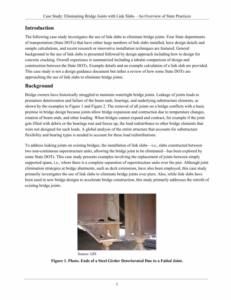
Introduction The following case study investigates the use of link slabs to eliminate bridge joints. Four State departments of transportation (State DOTs) that have either large numbers of link slabs installed, have design details and sample calculations, and recent research or innovative installation techniques are featured. General background in the use of link slabs is presented followed by design approach including how to design for concrete cracking. Overall experience is summarized including a tabular comparison of design and construction between the State DOTs. Example details and an example calculation of a link slab are provided. This case study is not a design guidance document but rather a review of how some State DOTs are approaching the use of link slabs to eliminate bridge joints.
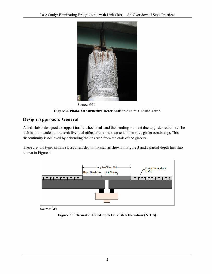
Background Bridge owners have historically struggled to maintain watertight bridge joints. Leakage of joints leads to premature deterioration and failure of the beam ends, bearings, and underlying substructure elements, as shown by the examples in Figure 1 and Figure 2. The removal of all joints on a bridge conflicts with a basic premise in bridge design because joints allow bridge expansion and contraction due to temperature changes, rotation of beam ends, and other loading. When bridges cannot expand and contract, for example if the joint gets filled with debris or the bearings rust and freeze up, the load redistributes to other bridge elements that were not designed for such loads. A global analysis of the entire structure that accounts for substructure flexibility and bearing types is needed to account for these load redistributions.
To address leaking joints on existing bridges, the installation of link slabs—i.e., slabs constructed between two non-continuous superstructure units, allowing the bridge joint to be eliminated—has been explored by some State DOTs. This case study presents examples involving the replacement of joints between simply supported spans, i.e., where there is a complete separation of superstructure units over the pier. Although joint elimination strategies at bridge abutments, such as deck extensions, have also been employed, this case study primarily investigates the use of link slabs to eliminate bridge joints over piers. Also, while link slabs have been used in new bridge designs to accelerate bridge construction, this study primarily addresses the retrofit of existing bridge joints.
Source: GPI
Figure 1. Photo. Ends of a Steel Girder Deteriorated Due to a Failed Joint.
Case Study: Eliminating Bridge Joints with Link Slabs – An Overview of State Practices
2
Source: GPI
Figure 2. Photo. Substructure Deterioration due to a Failed Joint.
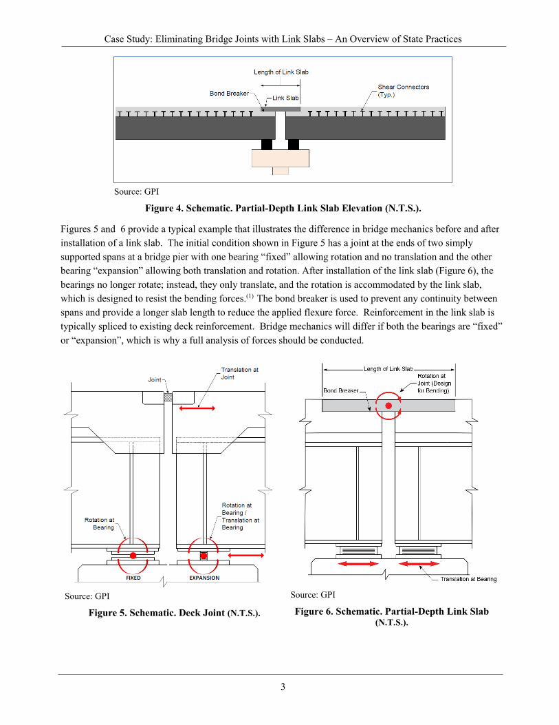
Design Approach: General A link slab is designed to support traffic wheel loads and the bending moment due to girder rotations. The slab is not intended to transmit live load effects from one span to another (i.e., girder continuity). This discontinuity is achieved by debonding the link slab from the ends of the girders.
There are two types of link slabs: a full-depth link slab as shown in Figure 3 and a partial-depth link slab shown in Figure 4.
Source: GPI
Figure 3. Schematic. Full-Depth Link Slab Elevation (N.T.S).
Case Study: Eliminating Bridge Joints with Link Slabs – An Overview of State Practices
3
Source: GPI
Figure 4. Schematic. Partial-Depth Link Slab Elevation (N.T.S.).
Figures 5 and 6 provide a typical example that illustrates the difference in bridge mechanics before and after installation of a link slab. The initial condition shown in Figure 5 has a joint at the ends of two simply supported spans at a bridge pier with one bearing “fixed” allowing rotation and no translation and the other bearing “expansion” allowing both translation and rotation. After installation of the link slab (Figure 6), the bearings no longer rotate; instead, they only translate, and the rotation is accommodated by the link slab, which is designed to resist the bending forces.(1) The bond breaker is used to prevent any continuity between spans and provide a longer slab length to reduce the applied flexure force. Reinforcement in the link slab is typically spliced to existing deck reinforcement. Bridge mechanics will differ if both the bearings are “fixed” or “expansion”, which is why a full analysis of forces should be conducted.
Source: GPI
Figure 5. Schematic. Deck Joint (N.T.S.).
Source: GPI
Figure 6. Schematic. Partial-Depth Link Slab (N.T.S.).

Case Study: Eliminating Bridge Joints with Link Slabs – An Overview of State Practices
4
Design Approach: Impact on Existing Bearings The span arrangement of the bridge typically accommodates overall bridge expansion and contraction. A global analysis of the bridge to determine structural flexibility and horizontal loads can reveal bearings that need to be modified or replaced.
Virginia Department of Transportation Approach
The Virginia department of transportation (VDOT) requires that existing bearings be evaluated according to the new forces due to installation of the link slab. This may result in converting fixed bearings to expansion, increasing the capacity of expansion bearings, and replacing fixed bearings.(3)
Massachusetts Department of Transportation Approach
The Massachusetts department of transportation (MassDOT) where feasible replaces existing steel bearings with elastomeric bearings that allow for rotation and translation in all directions. In some situations, the bearings are retained if they are either a fixed-fixed or expansion-expansion configuration. While most State DOTs prefer to replace bearings at a fixed-fixed configuration when installing link slabs, MassDOT does allow fixed bearings to remain if the span lengths are less than 100 ft.(5) This saves the cost of bearing replacement, which typically involves superstructure jacking, bearing removal, new bearing installation and costs associated with impact on traffic.
New York State Department of Transportation Approach
The New York State department of transportation (NYSDOT) does not use link slabs with a fixed-fixed bearing configuration. Further, its guidance states that steel rocker and sliding bearings are not suitable for link slabs due to the repetitive horizontal movements induced by girder live load deflections.(2) An example of a NYSDOT link slab is shown in Figure 7.
Source: NYSDOT
Figure 7. Photo. Link Slab, Rte. 51 over Erie Canal, CSX, Rte. 5 Ilion, NY.

Case Study: Eliminating Bridge Joints with Link Slabs – An Overview of State Practices
5
Maryland Transportation Authority Approach
In a recent project, the Maryland Transportation Authority (MDTA) used link slabs under fixed-fixed and expansion-expansion conditions. The existing fixed bearings were modified by adding slotted holes in the sole plate to relieve thermal stresses.(9)
Design Approach: Effect on Concrete Cracking The approach to designing link slabs accounts for the redistribution of forces due to the elimination of a joint that had previously allowed for both translation and rotation. In an effort to minimize concrete cracking due to slab rotation some State DOTs are using concrete that can accommodate higher tensile stresses such as ultra-high performance concrete (UHPC) or other concrete materials that are fiber reinforced. Summarized below are brief examples of guidance provided by State DOTs to help design engineers minimize concrete cracking in link slabs. Table 1 in this document lists the specific type of concrete used.
VDOT Approach
According to its “Guidelines for Bridge Deck Joint Elimination,” VDOT’s current practice does not require link slabs to satisfy its concrete cracking width requirements at the serviceability limit states.(3) However, a research study began in the summer of 2020 for refining the design of partial-depth link slabs and for developing customized non-proprietary, fiber-reinforced concrete mixes to meet the strain requirements and strength-development expectations. An example of a VDOT link slab is shown in Figure 8.
Source: VDOT
Figure 8. Photo. I-64 Dunlap Creek Link Slab, Alleghany County, VA.
MassDOT Approach
To control cracking of the link slab concrete, MassDOT uses the American Association of State Highway Transportation Officials Load and Resistance Factor Design Specifications, 8th Edition, Equation 5.6.7, which is based on a physical cracking model. A conservative Class 2 gamma factor of 0.75 is used, which represents an allowable crack width of 0.13 inch.(5)

Case Study: Eliminating Bridge Joints with Link Slabs – An Overview of State Practices
6
NYSDOT Approach
To control cracking of the link slab concrete, NYSDOT uses the strain compatibility design method. NYSDOT designs for a maximum concrete strain of 0.0035 in tension, and a maximum stress of 14 kips per square inch (ksi) in compression. The ability of UHPC to develop ultimate tensile strains up to 0.007 by development of micro cracks allows the link slab to accommodate girder end rotations. A maximum design strain of 0.0035 at the extreme tensile fiber is chosen to control the crack width. The crack spacing associated with a strain of 0.0035 is approximately 3/16 inch, resulting in extremely fine cracks that are invisible to the naked eye. Limiting the tensile strain typically increases the service life of the link slab by preventing the penetration of moisture and chlorides.(2)
MDTA Approach
MDTA uses the NYSDOT approach to concrete cracking design. In addition to UHPC, MDTA also considers Engineered Cementitious Concrete (ECC) and limits the ultimate tensile strain of that material to 0.002.(9)
State Departments of Transportation Experience State DOTs have implemented link slabs as part of rehabilitation projects or in new construction. The link slab experience of these agencies is summarized below.
VDOT Experience
VDOT has installed link slabs throughout the State, and Chapter 32 of VDOT’s Manual of the Structure and Bridge Division contains instructions to designers on joint elimination and the use of link slabs. The use of link slabs to eliminate joints is ranked third and fourth in a hierarchy of options as follows: (1) structural continuity of deck and superstructure, (2) continuous deck for live load, (3) full-depth link slab, and (4) partial-depth link slab. VDOT does have a current research project underway with hopes of link slabs becoming the best option for joint elimination. According to Jeff Milton, VDOT State Bridge Preservation Engineer, “Leaking bridge deck expansion joints are the greatest contributor to bridge superstructure and substructure deterioration in Virginia. Link slabs and deck extensions have proven to be a cost-effective preservation technique available for addressing leaking joints.” VDOT has developed agency-defined elements to track structural condition over time by bridge inspectors. Sample VDOT details for a full depth link slab are shown in Figure 9.

Case Study: Eliminating Bridge Joints with Link Slabs – An Overview of State Practices
7
Source: VDOT
Figure 9. Schematic. Example Details for the Full-Depth Link Slab.
Deck Extensions - Link slabs do not fit the character of an abutment as there are not two portions of superstructure being joined. However, details that are similar to a link slab have been used to eliminate joints at abutments. VDOT refers to these as “Deck Extensions.” VDOT’s current hierarchy of options for eliminating bridge deck expansion joints at abutments is (1) use a semi-integral abutment, (2) use a deck extension, and (3) use the Virginia Abutment (an abutment with an integral trough). These deck extensions are typically 4 feet long and require no analysis unless the skew is greater than 30 degrees. The slab extension simply moves the joint to the back face of the backwall instead of the front face.(3) An example of a VDOT deck slab extension installment at an abutment is shown in Figure 10.
Source: VDOT
Figure 10. Photo. VDOT Deck Slab Extension Installation at Abutment.
Case Study: Eliminating Bridge Joints with Link Slabs – An Overview of State Practices
8
MassDOT Experience
MassDOT has installed link slabs throughout the State over the past 20 years. The projects include individual joint replacements as well as joining new prefabricated superstructure elements to facilitate accelerated bridge construction (ABC). In new construction, MassDOT has implemented link slabs in situations where unbalanced, continuous bridge spans would result in the uplift of end spans due to longer adjacent spans. In these situations, MassDOT has designed simple spans (thus preventing uplift in the short end spans) and used link slabs to eliminate the joint between the spans. The service life of link slabs has not been fully evaluated yet since the current installations are a maximum of 20 years old. However, based on positive performance to date, it may be reasonable to assume that the link slab service life would be equal to the surrounding concrete deck.
MassDOT uses different types of concrete based on traffic control, construction schedule and other needs for each individual project. When possible, standard concrete mix is used due to lower material costs and allowed to cure under standard procedures. In tighter traffic control situations where long duration lane closures would be especially undesirable, high early strength concretes have been used, with curing times ranging from a few hours to a few days depending on the situation. UHPC and mobile mix concrete have been implemented as well, with some projects using traditional design-bid-build procurement and some projects constructed under design-build procurement.
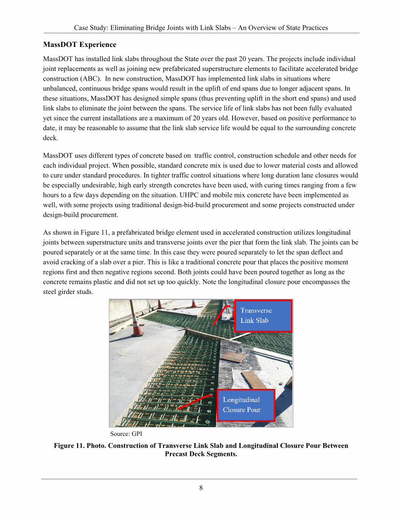
As shown in Figure 11, a prefabricated bridge element used in accelerated construction utilizes longitudinal joints between superstructure units and transverse joints over the pier that form the link slab. The joints can be poured separately or at the same time. In this case they were poured separately to let the span deflect and avoid cracking of a slab over a pier. This is like a traditional concrete pour that places the positive moment regions first and then negative regions second. Both joints could have been poured together as long as the concrete remains plastic and did not set up too quickly. Note the longitudinal closure pour encompasses the steel girder studs.
Source: GPI
Figure 11. Photo. Construction of Transverse Link Slab and Longitudinal Closure Pour Between Precast Deck Segments.
Case Study: Eliminating Bridge Joints with Link Slabs – An Overview of State Practices
9
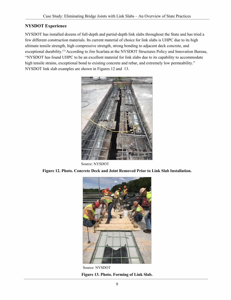
NYSDOT Experience
NYSDOT has installed dozens of full-depth and partial-depth link slabs throughout the State and has tried a few different construction materials. Its current material of choice for link slabs is UHPC due to its high ultimate tensile strength, high compressive strength, strong bonding to adjacent deck concrete, and exceptional durability.(1) According to Jim Scarlata at the NYSDOT Structures Policy and Innovation Bureau, “NYSDOT has found UHPC to be an excellent material for link slabs due to its capability to accommodate high tensile strains, exceptional bond to existing concrete and rebar, and extremely low permeability.” NYSDOT link slab examples are shown in Figures 12 and 13.
Source: NYSDOT
Figure 12. Photo. Concrete Deck and Joint Removed Prior to Link Slab Installation.
Source: NYSDOT
Figure 13. Photo. Forming of Link Slab.
Case Study: Eliminating Bridge Joints with Link Slabs – An Overview of State Practices
10
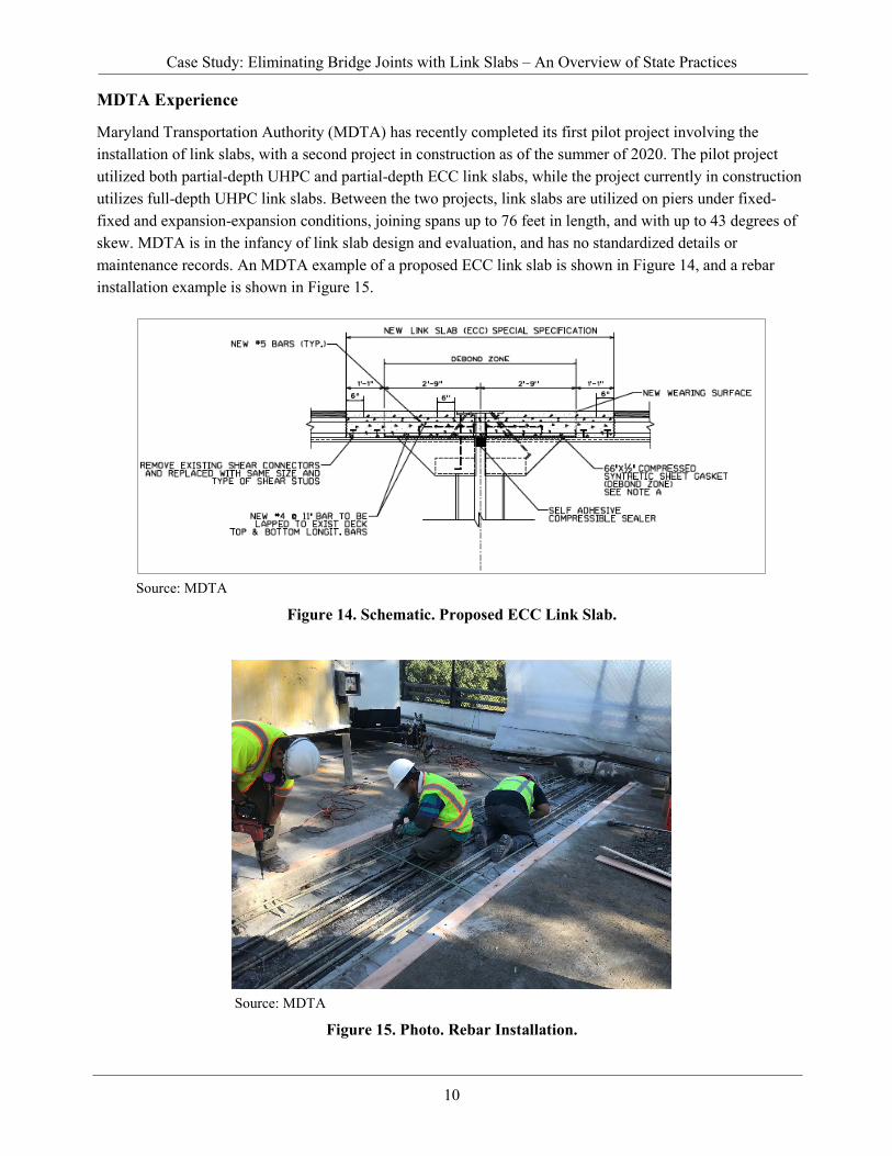
MDTA Experience
Maryland Transportation Authority (MDTA) has recently completed its first pilot project involving the installation of link slabs, with a second project in construction as of the summer of 2020. The pilot project utilized both partial-depth UHPC and partial-depth ECC link slabs, while the project currently in construction utilizes full-depth UHPC link slabs. Between the two projects, link slabs are utilized on piers under fixed-fixed and expansion-expansion conditions, joining spans up to 76 feet in length, and with up to 43 degrees of skew. MDTA is in the infancy of link slab design and evaluation, and has no standardized details or maintenance records. An MDTA example of a proposed ECC link slab is shown in Figure 14, and a rebar installation example is shown in Figure 15.
Source: MDTA
Figure 14. Schematic. Proposed ECC Link Slab.
Source: MDTA
Figure 15. Photo. Rebar Installation.
Case Study: Eliminating Bridge Joints with Link Slabs – An Overview of State Practices
11
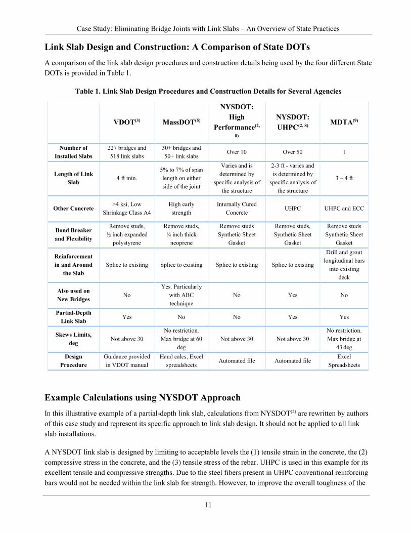
Link Slab Design and Construction: A Comparison of State DOTs A comparison of the link slab design procedures and construction details being used by the four different State DOTs is provided in Table 1.
Table 1. Link Slab Design Procedures and Construction Details for Several Agencies
Example Calculations using NYSDOT Approach In this illustrative example of a partial-depth link slab, calculations from NYSDOT(2) are rewritten by authors of this case study and represent its specific approach to link slab design. It should not be applied to all link slab installations.
A NYSDOT link slab is designed by limiting to acceptable levels the (1) tensile strain in the concrete, the (2) compressive stress in the concrete, and the (3) tensile stress of the rebar. UHPC is used in this example for its excellent tensile and compressive strengths. Due to the steel fibers present in UHPC conventional reinforcing bars would not be needed within the link slab for strength. However, to improve the overall toughness of the
VDOT(3) MassDOT(5)
NYSDOT: High
Performance(2,
8)
NYSDOT: UHPC(2, 8)
MDTA(9)
Number of Installed Slabs
227 bridges and 518 link slabs
30+ bridges and 50+ link slabs
Over 10 Over 50 1
Length of Link Slab
4 ft min. 5% to 7% of span length on either side of the joint
Varies and is determined by
specific analysis of the structure
2-3 ft - varies and is determined by
specific analysis of the structure
3 – 4 ft
Other Concrete >4 ksi, Low
Shrinkage Class A4 High early
strength Internally Cured
Concrete UHPC
UHPC and ECC
Bond Breaker and Flexibility
Remove studs, ½ inch expanded
polystyrene
Remove studs, ¼ inch thick
neoprene
Remove studs Synthetic Sheet
Gasket
Remove studs, Synthetic Sheet
Gasket
Remove studs Synthetic Sheet
Gasket
Reinforcement in and Around
the Slab Splice to existing Splice to existing Splice to existing Splice to existing
Drill and grout longitudinal bars
into existing deck
Also used on New Bridges
No Yes. Particularly
with ABC technique
No Yes No
Partial-Depth Link Slab
Yes No No Yes Yes
Skews Limits,
deg Not above 30
No restriction. Max bridge at 60
deg Not above 30 Not above 30
No restriction. Max bridge at
43 deg Design
Procedure Guidance provided in VDOT manual
Hand calcs, Excel spreadsheets
Automated file Automated file Excel
Spreadsheets

Case Study: Eliminating Bridge Joints with Link Slabs – An Overview of State Practices
12
system one layer of longitudinal reinforcement is provided in the center of the link slab. The size, spacing, and type should match that of the adjacent concrete deck.
Source: NYSDOT
Figure 16. Schematic. NYSDOT Partial-Depth Link Slab.
In this example, the acceptable material limits are:
• Tensile strain in concrete limited to 0.0035. • Compressive stress in concrete limited to 14 ksi. • Tensile stress in rebar limited to 60 ksi.
Design considerations are:
• Length of unbonded portion of the link slab is 16 inch. This is the portion that will be subject to rotation of the girders.
• Span length to the left of the link slab is 80 ft. • Span length to the right of the link slab is 80 ft. • Unfactored live load girder end rotation is 0.29 deg. • Link slab thickness is 4 inch. • Link slab rebar will be #5 at 6 inch spacing placed at mid height of slab is 2 inch. • Design for a one-foot section so #5 rebar (0.31 in2) at 6 inch is 0.62 in2 per linear foot.
Case Study: Eliminating Bridge Joints with Link Slabs – An Overview of State Practices
13
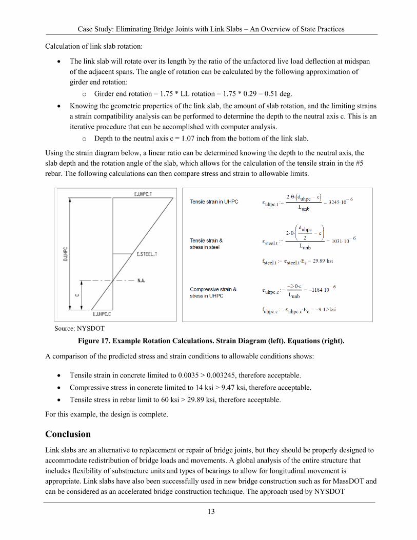
Calculation of link slab rotation:
• The link slab will rotate over its length by the ratio of the unfactored live load deflection at midspan of the adjacent spans. The angle of rotation can be calculated by the following approximation of girder end rotation:
o Girder end rotation = 1.75 * LL rotation = 1.75 * 0.29 = 0.51 deg. • Knowing the geometric properties of the link slab, the amount of slab rotation, and the limiting strains
a strain compatibility analysis can be performed to determine the depth to the neutral axis c. This is an iterative procedure that can be accomplished with computer analysis.
o Depth to the neutral axis c = 1.07 inch from the bottom of the link slab.
Using the strain diagram below, a linear ratio can be determined knowing the depth to the neutral axis, the slab depth and the rotation angle of the slab, which allows for the calculation of the tensile strain in the #5 rebar. The following calculations can then compare stress and strain to allowable limits.
Source: NYSDOT
Figure 17. Example Rotation Calculations. Strain Diagram (left). Equations (right).
A comparison of the predicted stress and strain conditions to allowable conditions shows:
• Tensile strain in concrete limited to 0.0035 > 0.003245, therefore acceptable. • Compressive stress in concrete limited to 14 ksi > 9.47 ksi, therefore acceptable. • Tensile stress in rebar limit to 60 ksi > 29.89 ksi, therefore acceptable.
For this example, the design is complete.
Conclusion Link slabs are an alternative to replacement or repair of bridge joints, but they should be properly designed to accommodate redistribution of bridge loads and movements. A global analysis of the entire structure that includes flexibility of substructure units and types of bearings to allow for longitudinal movement is appropriate. Link slabs have also been successfully used in new bridge construction such as for MassDOT and can be considered as an accelerated bridge construction technique. The approach used by NYSDOT

Case Study: Eliminating Bridge Joints with Link Slabs – An Overview of State Practices
14
incorporating UHPC for partial-depth link slabs has been adopted by MDTA in its current research project and is also being investigated by VDOT through new research. Installed link slabs should be monitored for performance, perhaps as an Agency-added element to the bridge element inspection method.
Resources Scarlata, J. (2017). “UHPC Link Slab Design.” Presented at the NYSDOT 2017 Ultra High Performance
Concrete (UHPC) Workshop, Albany, NY, found at https://www.dot.ny.gov/divisions/engineering/structures/repository/events-news/NYSDOT_2017_UHPC_Workshop_Scarlata.pdf
New York State Department of Transportation. Link Slab Design, Albany, NY, found at: https://www.dot.ny.gov/main/business-center/designbuildproject39/repository/Link%20Slab%20Design%20EX.pdf
Virginia Department of Transportation. (2018). Manual of the Structure and Bridge Division, Part 2, Chapter 32, File No. 32.09-1, Richmond, VA, found at http://www.virginiadot.org/business/resources/bridge/Manuals/Part2/Chapter32.pdf
Li, V., Lepech, M., Li, M. (2005). Field Demonstration of Durable Link Slabs for Jointless Bridge Decks Based on Strain-Hardening Cementitious Concrete, Research Report RC-1471, The Advanced Civil Engineering Materials Research Laboratory, Department of Civil and Environmental Engineering, University of Michigan, Ann Arbor, MI, found at https://www.michigan.gov/documents/mdot/MDOT_Research_Report_RC1471_200102_7.pdf
Massachusetts Department of Transportation. (2020). LRFD Bridge Design Manual – 2020 Edition, Part I – Design Guidelines, Chapter 3: LRFD Bridge Design Guidelines, Section 3.5.2.8, Boston, MA found at https://www.mass.gov/doc/chapter-3-lrfd-bridge-design-guidelines/download
Civjan, S. and Quinn, B. (2016). Better Bridge Joint Technology, Report No. UMTC-16.01, Department of Civil and Environmental Engineering, University of Massachusetts Amherst, Amherst, MA, found at https://www.umasstransportationcenter.org/umtc/Publications1.asp
Virginia Department of Transportation. (2016). VDOT Supplement to the AASHTO Manual for Bridge Element Inspection, Richmond, VA, found at http://www.virginiadot.org/business/resources/bridge/VDOT_Suppl_to_the_AASHTO_Manual_for_Bridge_Element_Insp_2016.pdf
New York State Department of Transportation. (2019). Link Slab Details, Albany, NY, found at https://www.dot.ny.gov/main/business-center/designbuildproject47/repository/X73163_Link%20Slab%20Details%20-%2020190115.pdf
Maryland Department of Transportation Maryland Transportation Authority. (2020) MDTA Link Slab Study. The BEST Center, University of Maryland, Chung C. Fu, Ph.D, P.E. Director.
Azizinamini, A., PhD. (2018). ABC-UTC Guide for “Superstructure to Pier Connection in SDCL Steel Bridge Systems. Florida International University.
Bridge Engineering Center, Iowa State University (2018), “Material Design and Structural Configuration of Link Slabs for ABC Applications” Completed. https://abc-utc.fiu.edu/wp-content/uploads/sites/52/2019/01/ISU-Link-Slab-Final-Report.pdf
Virginia Department of Transportation, Target Date for Research Completion “Concrete Mix Designs for Partial-Depth Link Slabs and Deck Extension” http://vtrc.virginiadot.org/ProjDetails.aspx?ID=709

15
For additional information, please contact: Raj Ailaney, PE Senior Bridge Engineer FHWA Office of Bridges and Structures Phone: (202)-366-6749 Email: [email protected]
Publication No. FHWA-HIF-20-062