case study: alson e. hatheway inc (aeh)documents.mscsoftware.com/cdn/farfuture/6ch1... ·...
TRANSCRIPT
Mechanical Design of Optical Systems using MSC Nastran
Case Study: Alson E. Hatheway Inc (AEH)
MSC Software | CASE STUDY
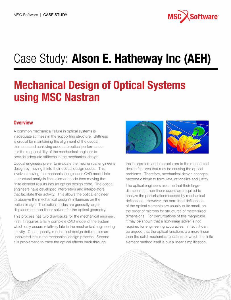
Overview
A common mechanical failure in optical systems is inadequate stiffness in the supporting structure. Stiffness is crucial for maintaining the alignment of the optical elements and achieving adequate optical performance. It is the responsibility of the mechanical engineer to provide adequate stiffness in the mechanical design.
Optical engineers prefer to evaluate the mechanical engineer’s design by moving it into their optical design codes. This involves moving the mechanical engineer’s CAD model into a structural analysis finite element code then moving the finite element results into an optical design code. The optical engineers have developed interpreters and interpolators that facilitate their activity. This allows the optical engineer to observe the mechanical design’s influences on the optical image. The optical codes are generally large-displacement non-linear solvers for the optical geometry.
This process has two drawbacks for the mechanical engineer. First, it requires a fairly complete CAD model of the system which only occurs relatively late in the mechanical engineering activity. Consequently, mechanical design deficiencies are uncovered late in the mechanical design process. Second, it is problematic to trace the optical effects back through
the interpreters and interpolators to the mechanical design features that may be causing the optical problems. Therefore, mechanical design changes become difficult to formulate, rationalize and justify.
The optical engineers assume that their large-displacement non-linear codes are required to analyze the perturbations caused by mechanical deflections. However, the permitted deflections of the optical elements are usually quite small, on the order of microns for structures of meter-sized dimensions. For perturbations of this magnitude it may be shown that a non-linear solver is not required for engineering accuracies. In fact, it can be argued that the optical functions are more linear than the solid mechanics functions, of which the finite element method itself is but a linear simplification.
“AEH/Ivory and MSC Nastran save projects months of schedule time and hundreds of thousands of dollars in costs by assuring that the optical structures are adequately stiff from the very beginning of the mechanical engineering effort.”Alson Hatheway, President AEH Inc.
Challenge The job of the mechanical engineer in the design of optical systems is to survey the mechanical design spaces looking for potential optical problems. For this, the engineer needs tools to relate the mechanical behavior of the design to the optical behavior of the system. They need to be applicable to early, simplified design concepts as well as the finalized detailed CAD model. And they need to be consistent with any analyses the optical engineers and structural engineers may make later in the project.
Solution/ValidationA solution is to provide software tools that let the mechanical engineer directly analyze how the mechanical design affects optical performance, without having to rely on optical engineers or their specialized optical codes. The Ivory Optomechanical Modeling Tools (AEH/Ivory) from Alson E. Hatheway Inc. (AEH) enable early, rapid, efficient evaluation of the optical adequacy of an optomechanical design solely by mechanical engineers working entirely within the MSC Nastran finite element analysis code. This also eliminates the potential for uncertainty and error in exchanging data between mechanical and optical codes.
AEH/Ivory also supports longhand calculations and Excel spreadsheet analyses that are often used in conjunction with the MSC Nastran results.
In a project to design a hyper-spectral imager, AEH/Ivory was used to import, as a bulk data file, the system’s optical prescription into MSC Nastran, trace all the optical images through the system and report the static and dynamic motions of the final image on the detector as calculated by MSC Nastran. This approach gave meaningful numbers early about how adequate the stiffness was and also let those values be traced throughout the development process.
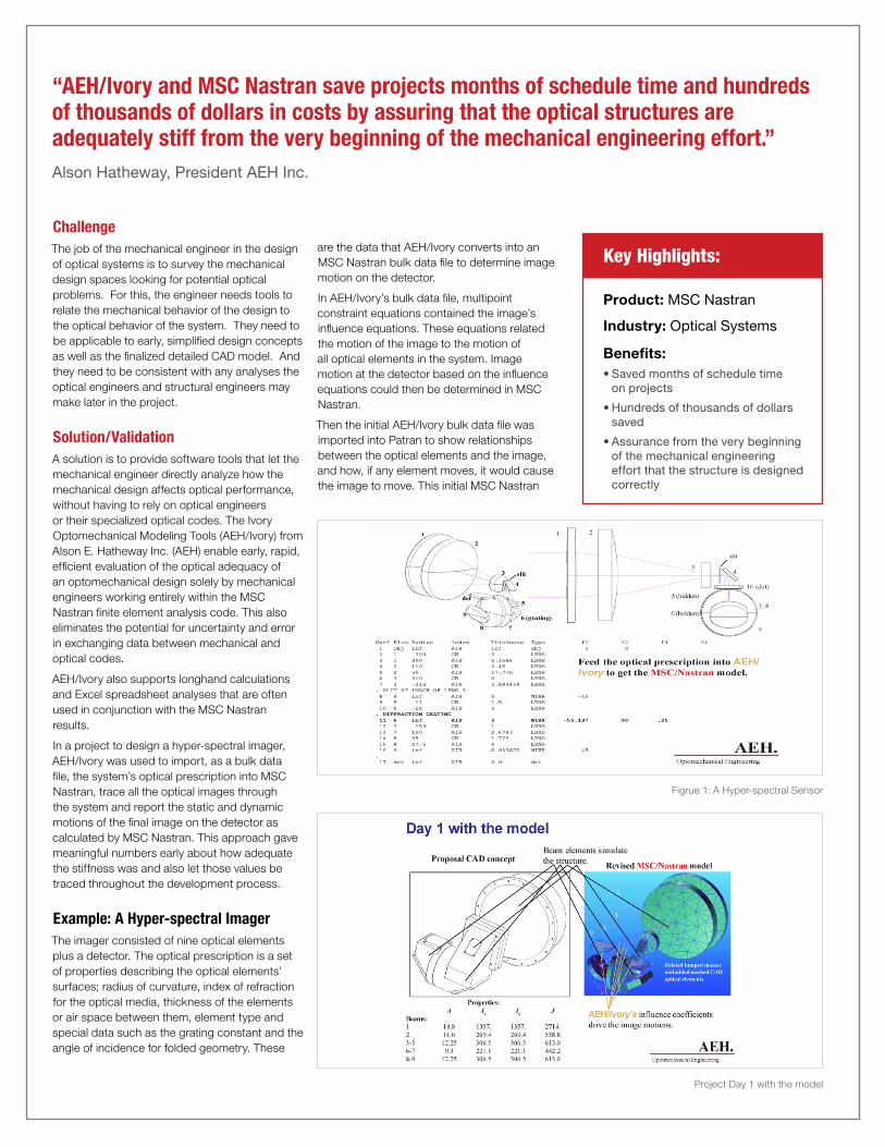
Example: A Hyper-spectral ImagerThe imager consisted of nine optical elements plus a detector. The optical prescription is a set of properties describing the optical elements’ surfaces; radius of curvature, index of refraction for the optical media, thickness of the elements or air space between them, element type and special data such as the grating constant and the angle of incidence for folded geometry. These
Figrue 1: A Hyper-spectral Sensor
Project Day 1 with the model
Product: MSC Nastran
Industry: Optical Systems
Benefits:• Saved months of schedule time
on projects
• Hundreds of thousands of dollars saved
• Assurance from the very beginning of the mechanical engineering effort that the structure is designed correctly
Key Highlights:are the data that AEH/Ivory converts into an MSC Nastran bulk data file to determine image motion on the detector.
In AEH/Ivory’s bulk data file, multipoint constraint equations contained the image’s influence equations. These equations related the motion of the image to the motion of all optical elements in the system. Image motion at the detector based on the influence equations could then be determined in MSC Nastran.
Then the initial AEH/Ivory bulk data file was imported into Patran to show relationships between the optical elements and the image, and how, if any element moves, it would cause the image to move. This initial MSC Nastran
Project Day 2 with the model
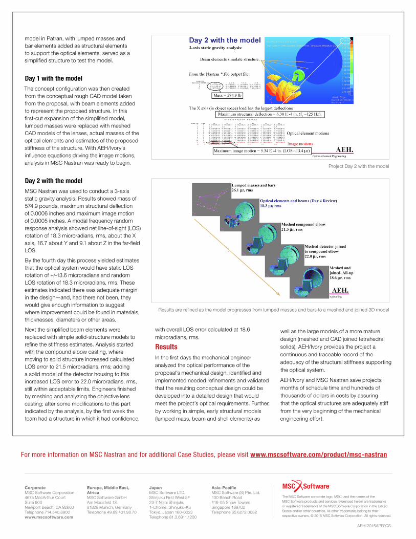
Results are refined as the model progresses from lumped masses and bars to a meshed and joined 3D model
model in Patran, with lumped masses and bar elements added as structural elements to support the optical elements, served as a simplified structure to test the model.
Day 1 with the model The concept configuration was then created from the conceptual rough CAD model taken from the proposal, with beam elements added to represent the proposed structure. In this first-cut expansion of the simplified model, lumped masses were replaced with meshed CAD models of the lenses, actual masses of the optical elements and estimates of the proposed stiffness of the structure. With AEH/Ivory’s influence equations driving the image motions, analysis in MSC Nastran was ready to begin.
Day 2 with the modelMSC Nastran was used to conduct a 3-axis static gravity analysis. Results showed mass of 574.9 pounds, maximum structural deflection of 0.0006 inches and maximum image motion of 0.0005 inches. A modal frequency random response analysis showed net line-of-sight (LOS) rotation of 18.3 microradians, rms, about the X axis, 16.7 about Y and 9.1 about Z in the far-field LOS.
By the fourth day this process yielded estimates that the optical system would have static LOS rotation of +/-13.6 microradians and random LOS rotation of 18.3 microradians, rms. These estimates indicated there was adequate margin in the design—and, had there not been, they would give enough information to suggest where improvement could be found in materials, thicknesses, diameters or other areas.
Next the simplified beam elements were replaced with simple solid-structure models to refine the stiffness estimates. Analysis started with the compound elbow casting, where moving to solid structure increased calculated LOS error to 21.5 microradians, rms; adding a solid model of the detector housing to this increased LOS error to 22.0 microradians, rms, still within acceptable limits. Engineers finished by meshing and analyzing the objective lens casting; after some modifications to this part indicated by the analysis, by the first week the team had a structure in which it had confidence,
with overall LOS error calculated at 18.6 microradians, rms.
Results In the first days the mechanical engineer analyzed the optical performance of the proposal’s mechanical design, identified and implemented needed refinements and validated that the resulting conceptual design could be developed into a detailed design that would meet the project’s optical requirements. Further, by working in simple, early structural models (lumped mass, beam and shell elements) as
well as the large models of a more mature design (meshed and CAD joined tetrahedral solids), AEH/Ivory provides the project a continuous and traceable record of the adequacy of the structural stiffness supporting the optical system.
AEH/Ivory and MSC Nastran save projects months of schedule time and hundreds of thousands of dollars in costs by assuring that the optical structures are adequately stiff from the very beginning of the mechanical engineering effort.
Europe, Middle East, AfricaMSC Software GmbHAm Moosfeld 1381829 Munich, GermanyTelephone 49.89.431.98.70
JapanMSC Software LTD. Shinjuku First West 8F23-7 Nishi Shinjuku1-Chome, Shinjuku-KuTokyo, Japan 160-0023Telephone 81.3.6911.1200
Asia-PacificMSC Software (S) Pte. Ltd. 100 Beach Road#16-05 Shaw Towers Singapore 189702Telephone 65.6272.0082
CorporateMSC Software Corporation4675 MacArthur CourtSuite 900Newport Beach, CA 92660Telephone 714.540.8900www.mscsoftware.com
The MSC Software corporate logo, MSC, and the names of the MSC Software products and services referenced herein are trademarks or registered trademarks of the MSC.Software Corporation in the United States and/or other countries. All other trademarks belong to their respective owners. © 2015 MSC.Software Corporation. All rights reserved.
AEH*2015APR*CS
For more information on MSC Nastran and for additional Case Studies, please visit www.mscsoftware.com/product/msc-nastran