case histories of large diameter driven steel tubular
TRANSCRIPT

1st International Conference on Geomechanics and Geoenvironmental Engineering (iCGMGE 2017) 81
Case Histories of Large Diameter Driven Steel Tubular Piles on the East Coast of Australia
Henry Zhang1
1Principal Geotechnical Engineer, WSP (ex Parsons Brinkerhoff), Sydney, Australia
Corresponding author’s E-mail: [email protected]
Abstract
Large diameter (>900mm) driven tubular steel piles have become a preferred footing system for support of buildings, bridges and other structures because of their relative ease of installation, high capacity and low cost and have played an important role in the Pacific Highway upgrade project. This paper will discuss a few case histories on driven steel tubular piles on recent highway upgrade projects on the east coast of Australia. Common practice, issues with design, installation and quality assurance via Pile Dynamic Analyzer (PDA) test and pile dynamic monitoring (PDM) will be discussed; drivability, unit shaft and base resistance as indicated from PDA tests will be compared with published data.
Keywords: Driven tubular steel pile, PDA CAPWAP analysis, PDM, bridge foundation
1. INTRODUCTION
Bridge foundation design has become more challenging than before because of the demand for - Large axial and lateral pile resistance due to larger pier span, large unsupported pile length
because of large scour depth and/or poor ground condition, and large vessel impact load - Reduced construction time to reduce cost, and - Protection of threatened species (flora, fauna, and fish) which does not allow for any
construction during breeding season Large diameter open-ended driven steel tubular piles (LDOESPs) have become more attractive for bridge foundations on the east coast of Australia. This may be due to the following factors:
- Large axial and lateral resistance compared to smaller size driven piles which are normally in groups
- Short installation time compared to large diameter bored piles; - Good quality control using PDA and PDM; - Advanced piling technique; - Low environmental impact compared to replacement and full displacement type piles - Bedrock not too deep (normally within 50m in depth) - Removal of pile caps

1st International Conference on Geomechanics and Geoenvironmental Engineering (iCGMGE 2017) 82
In the past 5 years or so, driven steel tubular pile has been employed on many bridge projects on the Pacific Highway upgrade projects where the author has been involved. These include the following high profile projects:
- Macleay River and flood plain bridge at Kempsey, 3.2km, the longest bridge in Australia - Shark Creek Bridge at Maclean, under construction, >800m long - Harwood Bridge at Harwood, under construction, >1.5km long - Richmond River Bridge at Broadwater, under construction, 1.0 km long
2. COMMON PRACTICE FOR LDOESPS
The common practice for the geotechnical design of LDOESPs is as follows: - Design in accordance with Australian piling code AS2159 and Bridge Design Code AS5100.3,
specifications from government agencies, e.g. Specification B54 by Road and Maritime Services (RMS) of New South Wales, and project technical requirements, e.g. the Scope of Works and Technical Criteria by RMS
- Axial capacity calculation using static method based on published data in Australia or overseas, e.g. Zhang et. al (2012), French LCPC method, British IPC method and US API RP2A method
- No consensus on toe plug. Some consultants assume plug forms, some not. Others check for both plugged and unplugged cases.
- Driveability analysis to assess penetration length, energy and set - not every consultant does this, maybe due to relatively low confidence on this type of analysis or lack of such experience or both. However, it is common for piling contractors to engage a specialist consultant to perform such analysis.
- Lateral response and pile ground analysis normally conducted using commercial software, e.g. single pile analysis using L-pile, Wallap, Repute and PYGMY; Pile group analysis using Repute, DEFPIG, PIGLET, Flac 2D, Plaxis 2D and Plaxis 3D.
- PDA (signal matching method) testing ratio of 10-50%, with an average of 20%. The common practice for the construction of LDOESPs is as follows:
- Piling platform constructed and verified on site by an experienced geotechnical engineer prior to construction. Piling platform design is normally done by a temporary work consultant using the British Guidance BRE470; sometimes numerical analysis is conducted to assess the bearing pressure distribution especially for large cranes or piling rigs; DCP testing is commonly used to check the existing ground condition for design; sometimes CPT or vane shear tests are carried out to provide more accurate estimate of the foundation soil strength.
- Preboring and/or vibratory hammer is normally used to install the first and second segments, then a hydraulic impact hammer is used to drive the last segment to the target toe level (normally in rock)

1st International Conference on Geomechanics and Geoenvironmental Engineering (iCGMGE 2017) 83
- PDM is normally performed on the last segment driven by impact hammer to monitor the hammer performance, delivered energy, driving stress, blow count and set
- PDA CAPWAP analysis is conducted on representative piles based on a selected blow (from one of the last a few blows) at the end of driving (EOD) to check the mobilized bearing capacity; a restrike PDA test is normally done on the same pile in 24 hours to check the pile setup or relaxation (capacity increase or decrease with time). Normally the same hammer for driving the pile is used for PDA testing
- PDA CAPWAP analysis is also normally conducted on non-representative piles if they pull up 1m (or more) higher than the design toe level
- Hiley Formula and/or CASE Method is commonly used to verify the bearing capacity of non-representative piles
- Soil within the top 6 to 15m is then removed by drilling inside the tube and replaced with reinforced concrete plug; this is for structural and corrosion protection purposes only
- No static load test is conducted The following sections will discuss the issues and engineering solutions of LDOESPs in terms of design and construction.
3. CASE HISTORY 1 – AN OVERFLOW BRIDGE NEAR ILUKA, NSW
This is a 5-span bridge over a creek, with 2 piles at each abutment and pier. The steel pile yield strength is 350MPa with wall thickness of 16mm. One metre long, 32mm thick driving shoe was adopted to cater for hard driving in bedrock. Typical ground condition comprises 10m thick soil (loose to medium dense sand and stiff to very stiff clay) overlying very low to low strength siltstone. A 12-ton hydraulic hammer (Bruce SGH1212) was used for installation. Figure 1 shows the hammer and piles to be installed.
Figure 1. Piling Site of An Overflow Bridge near Iluka NSW

1st International Conference on Geomechanics and Geoenvironmental Engineering (iCGMGE 2017) 84
Pile design details and testing results are summarised in Table 1a and Table 1b below. Table 1a Pile design and PDA test capacity
Pile No Length(m) Diameter (m) ULS Load (kN) Energy (kJ) Set (mm) Capacity (kN)
NB-01 16.5 1.05 4900 105 2.5 7126 (RST)
N04-02 13.6 1.05 6800 108 1.0 8616 (RST)
N02-01 15.0 1.05 6800 116 0.9 8524 (RST)
Notes: ULS – ultimate axial compression; diameter refers to inner diameter; capacity from PDA CAPWAP
analysis; EOD = end of driving; RST = restrike
Table 1b Pile unit resistance from PDA testing
Pile No Soil shaft (kPa) Rock shaft (kPa) Mobilised rock base* (MPa)
NB-01 3 - 66 197 - 354 2.5
N04-02 3 - 69 167 - 430 2.7
N02-01 3 - 90 221 - 328 2.0
Notes: * full plug assumed The hammer was not performing well as expected with efficiency varying from about 70% to 90%. The low efficiency affected the production rate of pier piles and later had to be replaced by a new hammer to finish the job. The hammer was also not large enough to fully mobilise the pile bearing capacity for PDA testing.
4. CASE HISTORY 2 – TWIN BRIDGE NEAR WOODBURN, NSW
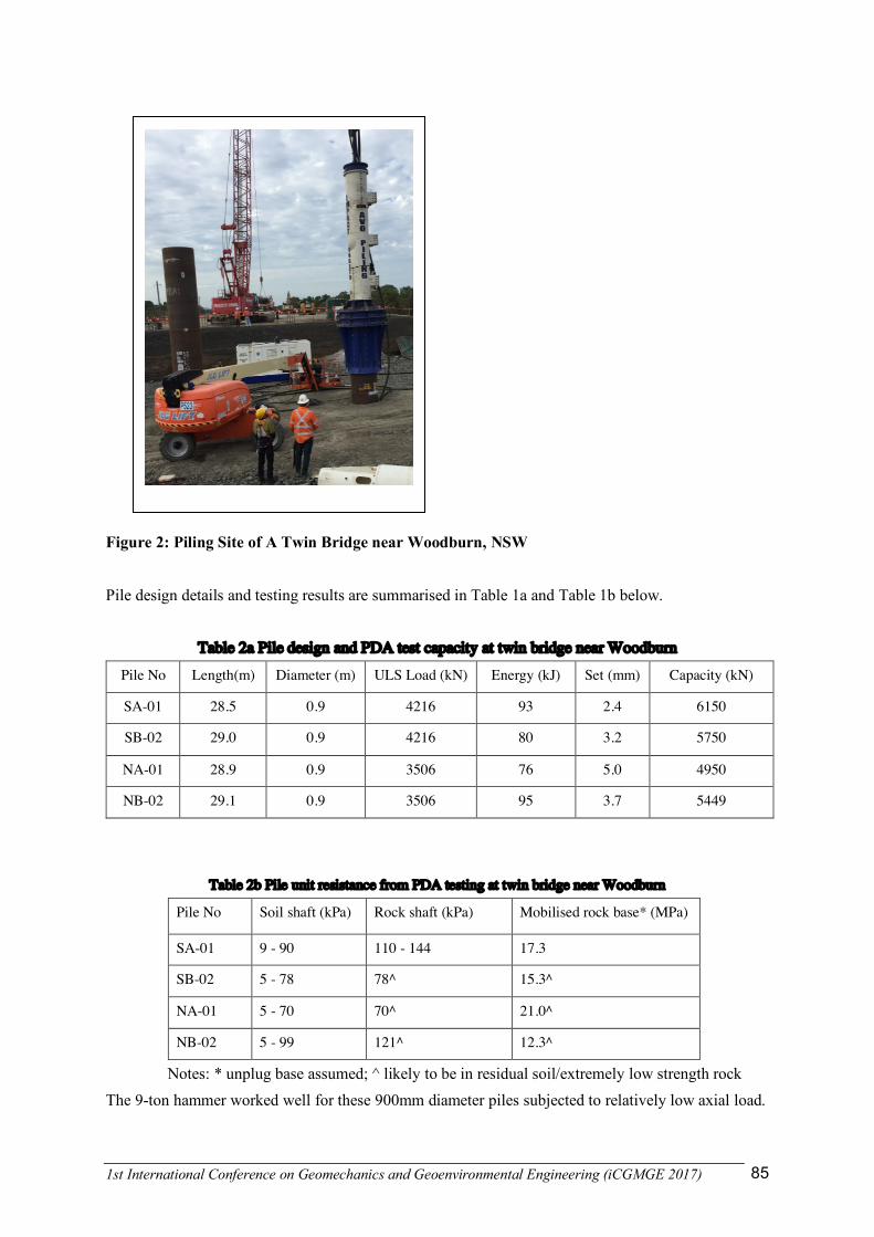
This is a single span twin bridge over a creek, with 2 piles at each abutment. The steel pile yield strength is 350MPa with wall thickness of 16mm. One metre long, 32mm thick driving shoe was adopted to cater for hard driving in bedrock. Typical ground condition comprises up to 28m thick soil (loose to dense sand and stiff to very stiff clay) overlying extremely low to low strength sandstone. A 9-ton hydraulic hammer (Juntttan HHK 9A) was used for driving. Figure 2 shows the pile hammer and piles to be driven to the target level.
1st International Conference on Geomechanics and Geoenvironmental Engineering (iCGMGE 2017) 85
Figure 2: Piling Site of A Twin Bridge near Woodburn, NSW
Pile design details and testing results are summarised in Table 1a and Table 1b below.
Table 2a Pile design and PDA test capacity at twin bridge near Woodburn
Pile No Length(m) Diameter (m) ULS Load (kN) Energy (kJ) Set (mm) Capacity (kN)
SA-01 28.5 0.9 4216 93 2.4 6150
SB-02 29.0 0.9 4216 80 3.2 5750
NA-01 28.9 0.9 3506 76 5.0 4950
NB-02 29.1 0.9 3506 95 3.7 5449
Table 2b Pile unit resistance from PDA testing at twin bridge near Woodburn
Pile No Soil shaft (kPa) Rock shaft (kPa) Mobilised rock base* (MPa)
SA-01 9 - 90 110 - 144 17.3
SB-02 5 - 78 78^ 15.3^
NA-01 5 - 70 70^ 21.0^
NB-02 5 - 99 121^ 12.3^
Notes: * unplug base assumed; ^ likely to be in residual soil/extremely low strength rock The 9-ton hammer worked well for these 900mm diameter piles subjected to relatively low axial load.

1st International Conference on Geomechanics and Geoenvironmental Engineering (iCGMGE 2017) 86
5. CASE HISTORY 3 – A MULTI-SPAN BRIDGE NEAR HARWOOD, NSW
This is a multi-span bridge over a river. Abutments are supported by 4x1200mm piles and piers are supported by 2x2400mm piles on land and 5x2000mm piles in river. The steel pile yield strength is 350MPa; the wall thickness is 16 and 25/28 mm for abutment and pier piles respectively. One meter long 50mm thick driving shoe was adopted. Typical ground condition comprises up to 35 to 60 m thick soil (loose to dense sand/gravel and very soft to very stiff clay) overlying extremely low to medium strength siltstone/sandstone. A vibratory hammer was used to vibrate the pile down to 30 to 40m, then a 14 or 25 tone elevated hydraulic hammer (IHC S-500 and IHC S-280) was used to drive the piles into rock. Figure 3 shows the vibratory hammer (left) and the impact hammer used for driving.
Figure 3: Left – A Vibratory Hammer on A Barge to Install River Piles. Right: An Impact Hammer to Install Land Piles. Selected pile design details and testing results are summarised in Table 3a and Table 3b below. Table 3a Pile design and PDA test capacity at a multi-span bridge near Harwood
Pile No Length(m) Diameter (m) ULS Load (kN) Energy (kJ) Set (mm) Capacity (kN)
P30A 65.0 2.4 23096 353 1.8 30500 (EOD)
P30A 65.0 2.4 23096 461 1.0 32300 (RST)
P26B 61.6 2.4 23850 400 1.9 30800 (RST)
P11C 31.7 2.0 12140 254 1.0 24500 (RST)
Table 3b Pile unit resistance from PDA testing at a multi-span bridge near Harwood

1st International Conference on Geomechanics and Geoenvironmental Engineering (iCGMGE 2017) 87
Pile No Soil shaft (kPa) Rock shaft (kPa) Mobilised rock base (MPa)
P30A 1 - 100 106 - 371 55.7 (4.5)* (EOD)
P30A 1 - 120 133 - 397 55.2 (4.5)* (RST)
P26B 1 - 105 119 - 383 52.2 (4.3)*
P11C 1 - 63 118 - 300 54.8 (5.3)*
Notes: * unplug and fully plugged (value in bracket) base assumed The hammers adopted were performing reasonably well. The PDA tests indicated much lower shaft resistance in soils (especially sand and gravel) than those recommended from API RP2A. This may be due to friction fatigue in granular materials (Fend & Yang, 2012) and shaft resistance degradation in clay (NCHRP Synthesis 478) for long piles (> 30m) due to the cyclic loading history at pile/soil interface during vibrating/driving. Set-up (increase of resistance with time) ranged from 10% up to 50% in shaft resistance was recorded in restrike testing. There was little change in base resistance from restrike testing, this may be due to the limitation of the impact hammer which was not big enough to fully mobilise the pile bearing capacity. The same hammer for driving the piles was used for PDA testing.
6. CONCLUSIONS & RECOMMENDATIONS
LDOEP piles becomes more attractive than other pile types on transportation projects in Australia. This paper discusses the common practice in the design and construction of LDOEP piles on the east coast of Australia. Three case histories were presented to summarise the information of both the design and construction verification using PDA testing. The following conclusions and recommendations may be made:
1. Plugging behaviour for LDOESPs is still subject to argument. The observation from the installation and PDA testing indicates that the reality is somewhere in between full plug and no plug. Degree of plugging reduces with increasing pile diameter.
2. Set-up was observed from all the projects that the author involved. Set-up occurred only to shaft resistance; it varied from 10% up to 80% within 1 to 7 days. It would be more efficient to consider the set-up in the design.
3. The mobilised shaft resistance for long piles (over 30m) could be significantly less than the published data such as API AP2A. The current practice relies heavily on dynamic monitoring and testing; however, the pile could behave differently under dynamic and static load. Thus more research is needed to understand the long term pile behaviour under static load.
4. LDOESPs will become more popular in transportation projects due to its various advantages.
ACKNOWLEDGMENTS The author would like to thank Mr Paul Hewitt for his peer review of this paper.

1st International Conference on Geomechanics and Geoenvironmental Engineering (iCGMGE 2017) 88
REFERENCES
API (American Petroleum Institute), 2007, Recommended practice for planning, designing and constructing fixed offshore platforms – working stress design, Errata and Supplement 3 Jardine, R., Chow, F., Overy, R. and Standing J. ICP Design methods for driven piles in sands and clays. ThomasTelford, London 2005. NCHRP Synthesis 478 – Design and load testing of large diameter open-ended piles. Yu, F. and Yang, M., 2012. Base Capacity of Open-Ended Steel Pipe Piles in Sand. Journal of Geotechnical and environmental Engineering, 138(9), 1116 – 1128 pp. Zhang H, Hewitt P, Yip G and Lin K, “Aspects of driven piles on Macleay River and floodplain bridge”, 8th Annual RMS Bridge Conference, 05 – 06 December 2012, Sydney