cascade flow problems - indian institute of...
TRANSCRIPT

ROYAL A LiSHMENT b i i I > J t ~ O h i O . REPORT 93
o h-ai O Q_
£ VISORY GROUP FOR AERONAUTIC
RESEARCH AND DEVELOPMENT
REPORT 93
CASCADE FLOW PROBLEMS
by
H. SCHLICHTING
FEBRUARY 1957
1
NORTH ATLANTIC TREATY ORGANIZATION
PALAIS DE CHAILLOT, PARIS 16


-
REPORT 93
NORTH ATLANTIC TREATY ORGANIZATION
ADVISORY GROUP FOR AERONAUTICAL RESEARCH AND DEVELOPMENT
CASCADE PLOW PROBLEMS
by
H. Schlichting
This Report was presented at the Tenth Meeting of the Wind Tunnel and Model Testing Panel, held from February 18th to 21st, 1957, in Paris

SUMMARY
In the Institute of Fluid Mechanics of the Engineering University of Braunschweig a considerable amount of research work on cascades has been done in recent years. Some of this work is reported very briefly here.
(i) An extensive program of theoretical calculations of loss coefficients of two-dimensional cascades in incompressible flow has been carried out, applying boundary layer theory to cascade flow. There is good agreement between theory and experiment.
(ii) Using the results of (i), and also results of secondary flow losses, the characteristic curves of an axial flow compressor (pressure coefficient and efficiency coefficient against mass flow coefficient) have been calculated purely theoretically. The tendency of these curves agrees with what is to be expected.
(iii) Some results of pressure distribution measurements on cascades at high subsonic Mach numbers are presented. These have been carried out in the new Variable Density High Speed Cascade Wind Tunnel of the Deutsche Forschungsanstalt fur Luftfahrt, Braunschweig. This wind tunnel allows independent variation of Reynolds number and Mach number.
533.695.5
3b5b2b
ii

SOMMAIRE
L'Institut de la M^canique des Fluides de 1'Ecole des Arts et Metiers
de Brunswick a effectue* beaucoup de recherches au sujet des grilles
d' aubes au cours de ces dernieres annees. Ce rapport donne un expose de
certains des travaux entrepris.
(1) Determination par le calcul des coefficients de perte des
grilles planes en regime incompressible, avec application a
1'ecoulement par les grilles de la theorie concernant la couche
limite. II existe un bon accord entre the'orie et expe'rience.
(ii) Determination th^orique des courbes caracteristiques d'un
compresseur axial (coefficients de pression et de rendement donnes en fonction de 1* e'coulement massique), en appliquant les re'sultats obtenus a (i) ainsi que ceux relatifs aux pertes en ecoulement secondaire. L' allure de ces courbes correspond a celle a laquelle on doit s'attendre.
(iii) Expose de certains resultats suivant des mesures relatives a la repartition de pression sur des grilles d*aubes pour une distribution de nombres de Mach subsoniques eleves, effectuees dans la nouvelle soufflerie a grille d*aubes a grande vitesse et a densite variable de la Deutsche Porschungsanstalt fur Luftfahrt, Brunswick. Cette soufflerie permet la variation independante des nombres de Reynolds et de Mach.
533.695.5
3b5b2b
iii

CONTENTS
Page
SUMMARY ii
LIST OF FIGURES v
NOTATION vi
1. INTRODUCTION 1
2. SCOPE OF INVESTIGATIONS 1
3. INCOMPRESSIBLE CASCADE FLOW 1
4. COMPRESSIBLE CASCADE FLOW 2
REFERENCES 4
FIGURES 5
DISTRIBUTION
iv

LIST OF FIGURES
Fig.l Loss coefficient £ =Ah/(& p w&2) for cascades of various solidity
ratios d/c and various blade angles /L; blade section NACA 0010;
Reynolds number R2 = w2c/io = 5xl05, fully turbulent boundary layer
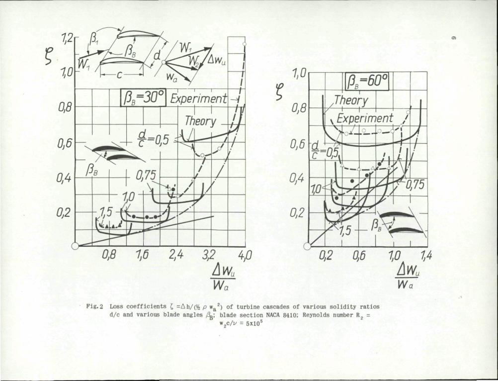
Pig.2 Loss coefficients £ =Ah/(& p w 2) of turbine cascades of various solidity ratios d/c and various blade angles /o ; blade section
NACA 8410; Reynolds number R? = w2c/io = 5xl05
Pig.3 Blade sections of the single-stage axial flow compressor of
Figure 4
Pig.4 Characteristic curves of a single-stage axial flow compressor, as
calculated theoretically from cascade data, by N. Scholz5. Pressure
coefficient ¥ = 2gH/uA2 and efficiency coefficient r) = H/Htn against
mass flow coefficient $ = V/(TT r»2u.)
Pig.5 Cascade geometry for pressure distribution measurements in the High
Speed Cascade Wind Tunnel; blade section NACA 0010
Page
9
Fig.6 Cascade geometry for pressure distribution measurements in the High
Speed Cascade Wind Tunnel; blade section NACA 8410 10
Pig.7 Pressure distribution measurements of cascades in compressible flow;
blade section NACA 0010; Reynolds number R2 = w2c/zo = 3xl05 11
Pig.8 Pressure distribution measurements of compressor cascades in
compressible flow; blade section NACA 8410; Reynolds number R2 =
w2c/v = 3xl05; see Figure 7 12
Pig.9 Pressure distribution measurements of turbine cascades in compres
sible flow; blade section NACA 8410; Reynolds number R2 = w2c/io =
5xl05; see Figure 7 13
Fig.10 Comparison of theoretical and experimental velocity distribution of
cascades in compressible flow. Theory from Prandtl-Glauert rule;
experiments, see Figure 7. Blade section NACA 0010; Reynolds number
R2 = w2c/io = 3xl05 14

NOTATION
d dis tance between blades
c blade chord
/3g blade angle
j 3 ^ angle of inflow
/32 angle of outflow
w 1 velocity of inflow
w ? velocity of outflow
w a axial component of velocity
A w u difference between circumferential velocity components behind and in front of cascade
^ wu^ wa deflection of flow through cascade
p density
v kinematic viscosity
Ah loss in total head
£ = Ah/rjjw2 , dimensionless loss coefficient
R = w2c/v, Reynolds number
a , a velocity of sound in front of cascade and behind cascade, respectively
Mj, M2 Mach numbers (= w1/a1 and * 2/a 2 respectively)
p Q stagnation pressure in front of cascade
p static pressure in front of cascade
p static pressure on blade surface
Axial compressor
u circumferential velocity of rotor at radial station r
vi

u A circumferential velocity of rotor at tip, r = r A
V volume flow per unit time
H, Hj.n actual head and theoretical head, respectively
$ - \ / ( T 7 T p U p i ) , dimensionless flow coefficient
f = 2gH/u|, pressure coefficient
77 = H/H t h, efficiency coefficient
vii


CASCADE FLOW PROBLEMS
H. Schlichting*
1. INTRODUCTION
The problem of the flow through cascades is an important one in the whole field of turbo-machinery, but it is a pure aerodynamic problem. The subject, in which considerable progress has been made in recent years, seems important enough to be discussed at a Meeting of the Wind Tunnel Panel, perhaps partly in conjunction with the Combustion and Propulsion Panel.
Some research work in this field has been done in Germany in recent years, and some new equipment has been built, so that Germany would be able to contribute some papers, if it is decided to discuss this subject at a future meeting.
This paper gives, very briefly, some ideas on the work done on the subject at Braunschweig University in recent years.
2. SCOPE OF INVESTIGATION
The main incentive of these Investigations is that real progress in the flow problems of turbo-machines will be achieved only by a deeper knowledge of complex flow phenomena. This requires extensive theoretical calculations which, however, need careful correlation with experiments. A general survey of these Investigations has been given in previous papers1'2.
The very complex cascade flow problem has been split up as follows:-
(i) Two-dimensional flow through cascades.
(a) Incompressible and inviscid flow.
(b) Incompressible, viscous flow. (c) Compressible flow.
( i i ) Three-dimensional flow through cascades.
(a) Secondary flow effects a t blade root and blade t i p . (b) Effects due to rad ia l divergence of the blades in cascades of ro ta t ional
symmetry.
3 . INCOMPRESSIBLE CASCADE FLOW
For two-dimensional cascades, the main object of the invest igat ions has been to find a way to ca lcula te theore t ica l ly the loss coeff icients of the cascade, since they depend on the geometrical and aerodynamic parameters of the cascade. This has been
* I n s t i t u t fur Stromungsmechanik, Technische Hochschule, Braunschweig, Germany and Deutsche Forschungsanstalt fur Luftfahrt , I n s t i t u t fur Aerodynamik, Braunschweig, Germany

2
achieved by applying boundary layer theory to the cascade flow. But before dealing with this problem, it was necessary to improve the methods of calculating the incompressible and inviscid flow through a cascade. Convenient solutions of the 'Indirect Problem' and the 'Direct Problem', have been published in two VDI-Forschungshefte3,u. These solutions have been used in an extensive programme of theoretical calculations of loss coefficients, in connection with a large amount of experimental work, mainly to check the theoretical results. Figures I and 2 show some examples of the loss coefficient plotted against the dimensionless deflection. In theory fully turbulent flow in the boundary layer has been assumed, and in the experiments this was achieved by a turbulence wire near to the leading edge of the blade. The results of Figure 1 are for cascades of blades with the symmetrical profile NACA 0010, whereas in Figure 2 the blades have the cambered profile NACA 8410. In both cases the solidity ratio d/c and the blade angle /L have been varied. The agreement between theory and experiment is very satisfactory.
These results on two-dimensional cascades, and some more on secondary flow losses, have finally enabled calculation, purely theoretically, of the characteristic curves of an axial flow compressor5. An example of this kind of calculations is given in Figure 3 and Figure 4. in Figure 3 the blading and the velocity vectors at different cross sections are given. Figure 4 shows the pressure coefficient 51 = 2gH/u«2 and the efficiency coefficient r/ for the single-stage compressor plotted against the dimensionless flow coefficient d) = \ / ( T T r A
2u A). The general shape of these curves agrees with what is expected, but no experiments to compare with these theoretical calculations have yet been carried out.
4. COMPRESSIBLE CASCADE FLOW*
In the past two years we have been engaged mainly on problems of three-dimensional cascade flow and of compressible cascade flow. Very extensive results have been accumulated on three-dimensional effects, but this subject is still far from being accessible to theory, and will not be dealt with here. Compressibility effects, however, are considered in a little more detail.
During the past year a special High Speed Cascade Wind Tunnel of the continuous flow type, for basic research work on compressibility effects, has been completed. A brief description of this tunnel was given at the Rome meeting of the Agard Wind Tunnel Panel6. A special feature of it is that the Mach number and the Reynolds number can be varied independently. This is regarded as very important for basic research on cascades, because the aerodynamic coefficients in most cases depend considerably on both the Mach number and the Reynolds number of the blade. The independent variation of Mach number and Reynolds number is achieved by installing the cascade wind tunnel in a tank which can be evacuated from 1 atm down to 0.1 atm. The Mach number range is from M = 0.2 to about 1.1. The blade length I = 300 mm and the blade chord c = 60 mm. In the meantime, since the Rome meeting, the tunnel has come into full operation.
During the past year an extensive programme of pressure distribution measurements has been carried out on cascade blades at high subsonic speeds. Figures 5 and 6 show the cascade
•These tests were done by Dr.-Ing. N. Scholz and Dlpl.-Ing. K.H. Grewe,

geometry of the whole programme. The cascade geometry and the blade profile are the same as in the earlier low speed investigations. Pressure distributions on all these cascades were measured at different angles of inflow and for Mach numbers from M = 0.2 to the choking Mach number. The Reynolds number is constant over the whole range
) 5. to the three cascades marked in solid black in Figure 5 and 6. of Mach numbers, R2 = w c / v = 3x10 . The results given in the following figures refer
In Figure 7 the cascade is unstaggered and of NACA 0010 profile, the angle of inflow being J3 l = 90° (zero lift) and /31 = 100°. With increasing Mach number the pressure distribution remains quite normal up to about Mj = 0.65 following the Prandtl-Glauert rule. For /3 = 100° and Mj =0.65 a shock wave first appears on the suction side of the blade. At Mx = 0.69 choking has occurred, and no further increase of Mach number is possible. With the onset of choking the pressure distribution changes completely, as can be seen from Figure 7 for Mx = 0.69. This is accompanied by a sudden increase of the pressure difference across the cascade, Pj-P^ which is also given in Figure 7.
In Figure 8 similar results are presented for a compressor cascade of blade profile NACA 8410 and blade angle /L = 135°. Here also the pressure distribution does not change its character up to M = 0.7. The choking Mach number is rather different for the two angles of inflow, being Mj = 0.75 for = 142°. but Mx = 0.90 for /31 = 148°. Due to the considerable amount of stagger, the increase of the pressure drop through the cascade is not as steep as with the unstaggered cascade.
In Figure 9 some results for a turbine cascade are given, the blade angle being /Og = 45° and the blade profile NACA 8410 again. Here the change of the pressure distribution, when approaching the choking Mach number, is not so abrupt as for the compressor cascade. This must be attributed to the favourable pressure gradient of the turbine cascade. If in this case the Mach number is referred to the outflow velocity, the choking Mach number is about M2 = 0.8.
A convenient method has been developed for calculating the pressure distribution according to the Prandtl-Glauert rule. In Figure 10 the experimental results of Figure 7 for the unstaggered cascade of NACA 0010 profile are compared with theoretical calculations. For high subsonic Mach numbers the compressibility effect on the pressure distribution is considerable. For those Mach numbers where no shock waves occur, the agreement of the theoretical and experimental pressure distributions is very satisfactory.
Later work on these cascades will Include measurements of loss coefficients.
It is hoped that measurements of this kind, which have apparently not been done systematically before, will contribute considerably in giving a clearer insight into the behaviour of flow in a compressor and a turbine at high speeds.

REFERENCES
1. Schlichting, H.
2. Schlichting, H.
Problems and Results of Invest igat ions on Cascade Flow. Journal of the Aeronautical Sciences, Vol.21. 1954,
p.163-178.
Some Problems of Cascade Flow. Proceedings of the Conference on High Speed Aeronautics. Polytechnic Insti
tute of Brooklyn, New York, Jan. 1955.
3. Scholz, N. Stromungsuntersuchungen an Schaufe lg i t te rn . Forschungsheft 442, 1954.
VDI-
4. Schlichting, H. Berechnung der reibungslosen inkompressiblen Strbmung fur ein vorgegebenes ebenes Schaufelgi t ter. VDI-Porschungsheft No.447, 1955.
5. Scholz, N.
6. Schlichting, H.
Berechnung der Kennlmie eines Axialverdichters auf Grund grenzschicht theoret ischer Gitteruntersuchungen. Jahrbuch der Wissenschaftlichen Gesellschaft fiir Luftfahrt (W.G.L.)
1955, p.205-213, 1956; see also Porschung auf dem Gebiet
des ingenieur Wesens, Vol.22, 1956, p.137-139.
The Variable Density High Speed Cascade Wind Tunnel of the Deutsche Forschungsanstalt fur Luftfahrt , Braunschweig. Paper presented at the Agard Meeting in Rome, February
1956; Agard-Report No.91. 1957.

0,4 Ofi
Wa
£=0,5
A - I
£-0,75
-0,8 -OA
Experiment Theory
Compressor
OA 0,8
Fig.l Loss coefficient £ =Ah/(^p w&2) for cascades of various solidity ratios d/c and
various blade angles /oL; blade section NACA 0010; Reynolds number R2 = w2c/iv = 5xl05, fully turbulent boundary layer
The circles with projected lines on the theoretical curves indicate the beginning of separation
? Vv
10-
Ofl i 1 r
PB~30 Experiment
05
-V
0,5 7,6 3,2 4,0 • 4 r V U
W0
5
0,2 0,6 1.0 A 1,4
Wa
Fig.2 Loss coefficients £ =Ah/(& p w&2) of turbine cascades of various solidity ratios
d/c and various blade angles / ; blade section NACA 8410: Reynolds number R2 = w2c/v = 5x10"

Section I (Tip) Section E Section HI Section IF (Hub) r/r„ 1.0 0,85 0,7 0,55
d/c 1,30 1,11 0,91 0,71 P B 13V 12V 113° 106{
ACjCm 0,575 0.5U7 0,589 0,695
i
c =vv-Pig.3 Blade sections of the single-stage axial flow compressor of Figure 4

myysyAZ'.
777/
®
CD
r
^
v//////.
/ / / / / / / y / y / y
TpvyTTTTTTp rA
© ®
rw
0^ Q4 Q5 ga
7? • j (
(Thl:lfth=0.d}6=0.m
Pressure coefficient. Jf—|p-
Section
r. y - 0 , 5 5
Mass flow coefficient^jffijj
Degree of reaction, r/rj=^or^j=co/?s/.=Q5
Pig.4 Characteristic curves of a single-stage axial flow compressor, as calculated theoretically from cascade data, by N. Scholz5. Pressure coefficient $ = 2gH/uA
2 and efficiency coefficient TO = H/Hth against mass flow coefficient $ = V/(w rA
2uA)

0.5
90' 120' 150'
_
^C=
0,75
1.0
1,25
Pig.5 Cascade geometry for pressure distribution measurements in the High Speed Cascade Wind Tunnel; blade section NACA 0010 <o

30'
0.75
60' 90 120' 135'
1.0
1.25
Pig.6 Cascade geometry for pressure distribution measurements in the High Speed Cascade Wind Tunnel; blade section NACA 8410

M, -0,25
-Oi
-04 Prior'
fir100°\ —i • • XL
Shockwave Choking
Fig.7 Pressure distribution measurements of cascades in compressible flow; blade section NACA 0010; Reynolds number R, = W.C/TO = 3x10s; see Figure 5
P-P Pressure coeff icient c n =
Pn-P Mj_ = w 1 / a 1
o r i
Mach number of inflow.

M,' 0,20 0,60 v
0.70 075 A-»" c - t O
0,-M
M,'0t20 0,50 0/0 0,90 CpoA
0,6 PrP*
WPo'Pi 0.2 fr%2*
otWmMi
' shock wave
-o.2Vy •at
r-M'rf, i i
choking
Pig.8 Pressure distribution measurements of compressor cascades in compressible HO; Reynolds see Figure 6
flow; blade section NACA 8410; Reynolds number R2 = w2c/v = 3xl05;

Mi-0,12
CP
Pr50\8 * -i i -16
P,-70°_
016 021
L
t'4 V
•*< • ^
y
s )
shock wave
0,225 n A-A
75 3 ± ± J _fX 76
9o~91
8
6
4 Shockwave 0,4 £J5 0,6 (t?
Fig.9 Pressure distribution measurements of turbine cascades in compressible flow; blade section NACA 8410; Reynolds number R2 = w2c/v = 5xl0
5; see Figure 6

M^0t25
fi=90
w_Vt
1.0
0,8 ' 0
^
X 1 c
/3=100
VV '
o P 1.2 W
Suction K^Side-
[Pressure 0.8^ Side'
0 x_ 1 c
055
0,8 ' 0
1.8
S
x 1 c
ih
1,2 W
y
- 1 08 ffl Jr*.
' 0 x_ 1 c
Theory
0.60
n pff m 0,8
o
1,6
V 1.1 1.2 1.0 OS
% .
1
\ \
• i J '
N ***«>
i r*
^
' 0 X 1 C
0.65 P,=so' H» 1,2 1.0
compr.
^
X 1 '0 c
Otjyvoapt
3 Pr100\
x_ 1 c
0 8 \ J K o r % r
' 0 A 1 c
• Experiment
0,1
Po'Pi - 0 1
\ oyfsi * - ^ - - ^ —
Theory
Sr. -90° 100°
0 02 Off 06 08
0 0,2 0,h Op 0,8 Ms,
Fig.10 Comparison of theoretical and experimental velocity distribution of cascades in compressible flow. Theory from Prandtl-Glauert rule; experiments, see
Figure 7. Blade section NACA 0010; Reynolds number R = w c / v = 3xl05

DISTRIBUTION
Copies of AGARD publications may be obtained in the various countries at the addresses given below.
On peut se procurer des exemplaires des publications de 1'AGARD aux adresses suivantes.
BELGIUM BELGIQUE
Centre National d'Etudes et de Recherches Aeronautiques 11, rue d' Egmont Bruxelles.
CANADA Director of Sc ien t i f ic Information Services, Defence Research Board Department of National Defence 'A' Building
Ottawa, Ontario.
DENMARK
DANEMARK
Military Research Board Defence Staff Kas te l le t Copenhagen 0.
FRANCE 0. N. E. R. A. ( D i r e c t i o n ) 25, avenue de la Division-Leclerc Chatillon-sous-Bagneux (Seine)
GERMANY
ALLEMAGNE
Wissenschaftliche Gesellschaft fur Luftfahrt Zentralstelle der Luftfahrtdokumentation Munchen 64, Flughafen Attn: Dr. H.J, Rautenberg
(jKfcjfcjC/hj
GRECE Greek Nat. Def. Gen. Staff B. MEO Athens.
ICELAND ISLANDE
Iceland Delegation to NATO Palais de Chaillot Paris 16.
ITALY ITALIE
Centre Consultivo Studi e Ricerche Ministero Difesa - Aeronautica Via Salaria 336 Rome.

LUXEMBURG LUXEMBOURG
Luxemburg Delegation to NATO Palais de Chaillot Paris 16,
NETHERLANDS PAYS BAS
Netherlands Delegation to AGARD 10 Kanaalstraat Delft, Holland.
NORWAY NORVEGE
Chief Engineering Division Royal Norwegian Air Force Deputy Chief of Staff/Material Myntgaten 2 Oslo. Attn: Major S. Heglund
PORTUGAL Subsecretariado da Estado da Aeronautica Av. da Liberdade 252 Lisbon. Attn: Lt. Col. Jose Pereira do
Nascimento
TURKEY TURQUIE
M. M. Vekaleti Erkaniharbiyei Umumiye Riyaseti Ilmi I s t i s a r e Kurulu Miidurlugii Ankara. Attn: Colonel Fuat Ulug
UNITED KINGDOM ROYAUME UNI
Ministry of Supply TIL, Room 009A First Avenue House High Hoiborn London, W. C. 1.
UNITED STATES ETATS UNIS
National Advisory Committee for Aeronautics 1512 H Street. N.W. Washington 25, D.C.
fc Printed by Technical Sdit ing and Reproduction Ltd
95 Great Port land S t . London, W.l.