cartridge valves specialy from italy close to emilia romani
DESCRIPTION
italian producer bucher hydraulics represents its cartritge valves.TRANSCRIPT

Screw-in Cartridges, Sandwich Bodies, Line-Mounting Bodies
The Size 16 Product Range
motion and progress
Multi-functionalCompact
EconomicalPressure: 420 barFlow Rate: 350 l/min
An Introduction to the Size 16 Product Range according to ISO 7789
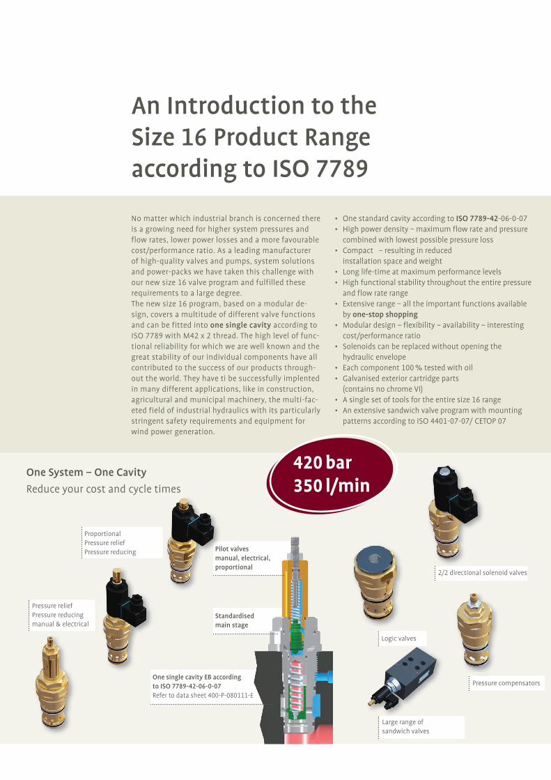
One System – One Cavity
Reduce your cost and cycle times
420 bar350 l/min
Pilot valvesmanual, electrical,proportional
No matter which industrial branch is concerned there is a growing need for higher system pressures and flow rates, lower power losses and a more favourable cost/performance ratio. As a leading manufacturer of high-quality valves and pumps, system solutions and power-packs we have taken this challenge with our new size 16 valve program and fulfilled these requirements to a large degree. The new size 16 program, based on a modular de-sign, covers a multitude of different valve functions and can be fitted into one single cavity according to ISO 7789 with M42 x 2 thread. The high level of func-tional reliability for which we are well known and the great stability of our individual components have all contributed to the success of our products through-out the world. They have ti be successfully implented in many different applications, like in construction, agricultural and municipal machinery, the multi-fac-eted field of industrial hydraulics with its particularly stringent safety requirements and equipment for wind power generation.
• One standard cavity according to ISO 7789-42-06-0-07• High power density – maximum flow rate and pressure combined with lowest possible pressure loss• Compact – resulting in reduced installation space and weight• Long life-time at maximum performance levels• High functional stability throughout the entire pressure and flow rate range• Extensive range – all the important functions available by one-stop shopping• Modular design – flexibility – availability – interesting cost/performance ratio• Solenoids can be replaced without opening the hydraulic envelope• Each component 100 % tested with oil• Galvanised exterior cartridge parts (contains no chrome VI)• A single set of tools for the entire size 16 range• An extensive sandwich valve program with mounting patterns according to ISO 4401-07-07/ CETOP 07
Standardised main stage
One single cavity EB according to ISO 7789-42-06-0-07Refer to data sheet 400-P-080111-E
ProportionalPressure reliefPressure reducing
Pressure reliefPressure reducingmanual & electrical
2/2 directional solenoid valves
Logic valves
Pressure compensators
Large range of sandwich valves

2/2 Directional Solenoid Cartridges
Design Bidirectional seat-valve shut-off, pilot operated seat-valve shut-off, pilot operated
Symbols 2
1
2
1
2
1
2
1
Series WS22G … WS22O … WR22G … WR22O …
Flow Rate / Pressure 350 l/min / 420 bar 350 l/min / 420 bar 350 l/min / 420 bar 350 l/min / 420 bar
Flow Direction 1 2 / 2 1 1 2 / 2 1
Pilot Oil No permanent pilot oil flow No permanent pilot oil flow
Data Sheet Reference 400-P-150101-E 400-P-150121-E
2/2 Directional Logic Cartridges
DesignActive control
seat-valve shut-off, direct actingPassive control
seat-valve shut-off, direct actingPassive control, soft switchingseat-valve shut-off, direct acting
Symbols 3
21
3
21
3
21
Series WL22SD … WL22SDL … WL22SDUR …
Flow Rate / Pressure 350 l/min / 420 bar 350 l/min / 420 bar 350 l/min / 420 bar
Area Ratio 2 : 1 2 : 1 2 : 1
Opening Pressure 0.4 / 2 / 6 / 10 / 13 bar 0.4 / 2 / 6 / 10 / 13 bar 0.4 / 2 / 6 / 10 / 13 bar
Flow Direction 1 2 / 2 1 1 2 / 2 1 1 2 / 2 1
Pilot Line 3 Integrated orifice,no pilot oil flow
Integrated orifice,pilot oil flow
Integrated orifice,pilot oil flow
Data Sheet Reference 400-P-160101-E 400-P-160121-E 400-P-160151-E
Manually Operated Pressure Cartridges
DesignPressure Relief
seated pilotPressure Relief
seated pilotPressure Relief
seated pilotPressure Reducing
seated pilot
Pilot Oil / External remotecontrol port
Internal to port 2 Internal to port 2/Remote control port 3
External pilot drain to port 3
External pilot drain to port 3
Symbols1 2 1 2
3
1 2
3
2 1
3
Series DVPB-1 … DVPB-2 … DVPB-3 … DRPB-5 …
Flow Rate / Pressure 350 l/min / 420 bar 350 l/min / 420 bar 350 l/min / 420 bar 250 l/min / 420 bar
Data Sheet Reference 400-P-285301-E 400-P-285311-E 400-P-285321-E 400-P-285401-E
Electrically Operated Pressure Cartridges (for 2 electrically adjustable pressures)
DesignPressure Relief
seated pilotPressure Relief
seated pilotPressure Relief
seated pilotPressure Reducing
seated pilot
Pilot Oil / External remotecontrol port
Internal to port 2 Internal to port 2/Remote control port 3
External pilot drain to port 3
External pilot drain to port 3
Symbols1 2 1 2
3
1 2
3
2 1
3
Series WUVPA-1 … WUVPA-2 … WUVPA-3 … WDRVPA-5 …
Flow Rate / Pressure 350 l/min / 420 bar 350 l/min / 420 bar 350 l/min / 420 bar 250 l/min / 420 bar
Data Sheet Reference 400-P-295301-E 400-P-295311-E 400-P-295321-E 400-P-295401-E
Pressure compensators
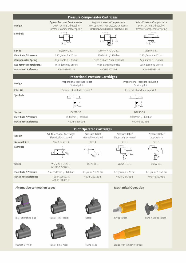
DIN / EN mating plug
Deutsch DT04-2P
Key operation
Junior-Timer Axial Flying leads
Hand wheel operation
Alternative connection types Mechanical Operation
Sealed with tamper-proof cap
Junior Timer Radial Kostal
Proportional Pressure Cartridges
Design Proportional Pressure Relief
Seated pilotProportional Pressure Reducing
Seated pilot
Pilot Oil External pilot drain to port 3 External pilot drain to port 3
Symbols1 2
3
2 1
3
Series DVPSB-3B … DRPSB-5B …
Flow Rate / Pressure 350 l/min / 350 bar 250 l/min / 350 bar
Data Sheet Reference 400-P-581601-E 400-P-581701-E
Pilot Operated Cartridges
Design2/2 Directional Cartridges
Electrically actuatedPressure Relief
Manually operatedPressure Relief
Electrically actuatedPressure Relief
proportional
Nominal Size Size 1 or size 3 Size 4 Size 1 Size 1
Symbols 1
2
2 1 2 1 2 1
Series WSP22G / OLA1 … WSP22G / ONA3 …
DDPC-1L … WUVA-1LO … DVSA-1L …
Flow Rate / Pressure 5 or 15 l/min / 420 bar 30 l/min / 420 bar 1.5 l/min / 420 bar 1.5 l/min / 350 bar
Data Sheet Reference 400-P-120601-E 400-P-120801-E
400-P-260111-E 400-P-287101-E 400-P-580101-E
Pressure Compensator Cartridges
Design Bypass Pressure Compensator
Direct acting, adjustable pressure compensator spring
Bypass Pressure CompensatorPilot operated, fixed pressure compensa-tor spring, with pressure relief function
Inline Pressure CompensatorDirect acting, adjustable
pressure compensator spring
Symbols1 2
3
1 2
3
2 1
3
Series DWDPA-2B … DWVPA / Y / Z-2B … DWDPA-5B …
Flow Rate / Pressure 350 l/min / 420 bar 350 l/min / 420 bar 250 l/min / 420 bar
Compensator Spring Adjustable 5 … 13 bar Fixed 5, 8 or 12 bar optional Adjustable 8 … 16 bar
Ext. remote control port 3 With damping orifice With damping orifice With damping orifice
Data Sheet Reference 400-P-330701-E 400-P-330711-E 400-P-330801-E

Bucher [email protected]
For further information please visit our website:www.bucherhydraulics.com
Sandwich Valves 2/2 Directional Solenoid OperatedDesign Bidirectional seat-valve shut-off, electrically operated (ON/OFF), pilot operated
Series SWS22G … / SWS22O …
Flow Rate / Pressure 300 l/min / 350 bar
Version Normally open or closed
Functions Inline function in P Bypass function in PT / AT / BT
Symbols
PX T B A Y
M
PX T B A Y
M
PX T B A Y PX T B A Y PX T B A Y
PX T B A Y PX T B A Y PX T B A Y
Mounting Pattern In accordance with ISO 4401-07-07 / Form A16 DIN 24340 / CETOP 07
Data Sheet Reference 400-P-240101-E
Sandwich Pressure Relief ValvesActuation Manually operated Electrically operated
Series SDVA … SWUVPA-1 …
Flow Rate / Pressure 300 l/min / 350 bar
Design Seated pilot, spool type
Functions Bypass function in PT / AT / BT
Symbols
PX T B A Y PX T B A Y PX T B A Y
Pressure Stages 100 / 160 / 250 / 350 bar
Pilot Oil Internal to port T
Mounting Pattern In accordance with ISO 4401-07-07 / Form A16 DIN 24340 / CETOP 07
Data Sheet Reference 400-P-308101-E 400-P-309101-E
Sandwich Pressure Reducing ValvesActuation Mechanically operated Electrically operated Electrical, proportional
Series SDRA … SWDRVPA-5 … SDRPSA-5 …
Flow Rate / Pressure 250 l/min / 350 bar 250 l/min / 350 bar 250 l/min / 350 bar
Design Seated pilot, spool type, with pressure-gauge port
Functions Inline function in P Inline function in P Inline function in P
Pilot Drain to Port Optional to port Y, A or B To port Y External to Port Y
Symbols
PX T B A Y
M
PX T B A Y
M
PX T B A Y
M
PX T B A Y
M
PX T B A Y
M
Y
Pressure Stages 100 / 160 / 250 / 350 bar
Mounting Pattern In accordance with ISO 4401-07-07 / Form A16 DIN 24340 / CETOP 07
Data Sheet Reference 400-P-308501-E 400-P-309501-E 400-P-593551-E
Line-Mounting BodiesSeries GEBAA …
Pressure 420 bar
Design with annular groove in port 2 for improved Dp values
Ports Ports 1 and 2 = G 1“ / Port 3 = G 1/4“
Data Sheet Reference 400-P-750115-E

© BUCHER HYDRAULICS GmbH 100-P-000098-E-00/01.2008
We reserve the right to implement changes without prior notice
Bucher [email protected]
For further information please visit our website:www.bucherhydraulics.com