cartridge and block spindles - gilman usa
TRANSCRIPT

Cartridge andblock spindlesA wide selection for milling, drilling, boring and other rotational processes

2 ©2011 Gilman USA, LLC
Visit www.GilmanUSA.com for more information.
Gilman USA completespindle selection

3©2011 Gilman USA, LLC
Gilman brandspindles
Take advantage of exclusive Gilman USA technologies and precision craftsmanship.• Whether your end application is a special machine or an OEM
product line, the Grafton, WI plant - along with three Gilman USA spindle facilities worldwide - assure you responsive engi-neering, precision manufacturing and prompt, efficient after-sale service.
• Emerging Gilman USA bearing technology allows Gilman USA to “push the envelope” in high speed belt driven performance: up to 12,000 RPM in 50 Taper and 15,000 RPM in 40 Taper tool-ing/tool holders. Gilman USA also provides OEM spindles, special retrofits and cluster spindle modules.
Table of contentsProduct features .................................................................... 4
Sizing instructions .................................................................. 5
Ordering instructions ............................................................ 6
1250 series: 1250P, N cartridge spindles ..........................................7
1875 series: 1875P, N cartridge spindles ..........................................8 1875N motorized spindles ............................................9
2750 series: 2750C cartridge spindles .............................................10 2750B block spindles ...................................................11 2750C motorized spindles ...........................................12 2750B motorized spindles ..........................................13 2750C motorized vertical travel spindles ..................14
3500 series: 3500C cartridge spindles .............................................16 3500B block spindles ...................................................17 3500C motorized spindles ...........................................18 3500B motorized spindles ..........................................19 3500C motorized vertical travel spindles ..................20
4000 series: 4000C cartridge spindles .............................................22 4000B block spindles ..................................................23 4000C motorized spindles ...........................................24 4000B motorized spindles ..........................................25 4000C motorized vertical travel spindles ..................26
Gilman USA delivers new quality products and services
5500 series: 5500C cartridge spindles ....................................... 28 5500B block spindles ............................................. 29 5500C motorized spindles ..................................... 30 5500B motorized spindles .................................... 31 5500C motorized vertical travel spindles ............ 32
6500 series: 6500C cartridge spindles ....................................... 34 6500B block spindles ............................................. 35 6500C motorized spindles ..................................... 36 6500B motorized spindles .................................... 37 6500C motorized vertical travel spindles ............ 38
8000 series: 8000C cartridge spindles ....................................... 40 8000B block spindles ............................................. 41 8000C motorized spindles ..................................... 42 8000B motorized spindles .................................... 43Specials ..................................................................... 44, 45
Accessories ................................................................46-48
Application engineering data ........................................ 49
Application examples ..................................................... 50
Idea bulletins .............................................................51-65
Spindle performance tips .............................................. 66
The “Engineering Handbook” for Gilman USA’s belt-driven spindle line.• In addition to drilling, milling, grinding and turning, Gilman
brand spindles have tackled many types of specialized machin-ing operations, including computer hard disk finishing, silicon wafer cutting, glass finishing and servo memory to name just a few call us to discuss your specialized applications.
• Unlike some products machined for accuracy after assem-bly, Gilman USA’s components are precision manufactured with state-of-the-industry boring and grinding equipment to millionths-of-inch tolerances before being assembled in our Class 10,000 clean room.
• Gilman USA is ISO 9001, 14001, and 18,000 certified for qual-ity systems and environmentally friendly processes.
All dimensions in inches unless otherwise indicated.

4 ©2011 Gilman USA, LLC
The Gilman brand spindle line
This catalog presents the current line of standard Gilman brand spindles, which are normally available for quick delivery from our extensive inventory stock. In these pages you’ll find a wide variety of spindle sizes and speeds, in configurations to meet most machine applications.
Standard Gilman brand spindles can be motorized belt-driven; they range in size from 1¦3 to 30 horsepower and are avail-able at fixed speeds. We can also supply a full range of spindle accessories including draw bars, coolant unions, wrenches, bearing sensors, lubricators and others.
If none of these standard spindles meet your requirements, a custom-designed spindle may well be the answer. Please refer to pages 44 and 45 for a review of Gilman USA custom capabili-ties. Then dial 1-800-445-6267 (In WI 262-377-2434) to discuss your needs with one of our application engineers.Key features of Gilman brand spindles Every Gilman brand precision spindle is built from the highest quality materials and components, to deliver high performance and long life. Features include:• High-quality alloy steel shaft. Case hardened and precision
ground, the shaft combines a hard outer surface with a tough, resilient core. Shaft threads are also precision ground, resulting in excellent accuracy.
• Precision grade ABEC-7 angular contact ball bearings are provided as standard. (Model 1250 and 1875 spindles feature ABEC-7 shielded deep groove ball bearings.) Bearings are lubricated with high performance synthetic grease.
• Close-grain, stress-relieved cast iron housings provide excel-lent dampening and heat-transfer properties.
• Precision runout tolerances down to .0001 T.I.R. are standard, depending on the size of the spindle unit. (Please refer to the adjoining chart.) Spindles with even higher precision (lower T.I.R. values) can be furnished on request.
Product features
• Highly effective standard sealing design includes labyrinth seals with flinging grooves and a gravity drain. Lower speed models feature Nitrile rubber V-ring seals. Air purging can be specified if desired. Models 1250 and 1875 feature a sealing method described on pages 7 and 8.
• Special materials and sealing methods can be used with any Gilman brand spindle, as may be required by unusual environ-mental situations.
• Motorized spindles incorporate a 230/460 volt 3-phase 60-Hz totally-enclosed fan-cooled motor, with timing belt drives, as standard. (Model 1875 spindles are furnished with a totally-en-closed non-ventilated motor.) Poly-V, V-belt, and flat belt drives are available for applications where high speed and minimum vibration are required.
• Vertical travel spindle units combine a motorized spindle with a slide assembly. The precise and rigid Gilman slide unit is constructed with oil-grooved low-friction bearing material on the saddle wear surfaces, guided on two precision-ground and hardened rectangular steel ways. Saddle tracking accuracy is .0005 inch per 3 feet of travel. Three different slide drives are offered: manual lead screw right angle drive, powered ball lead screw, and hydraulic cylinder.
Spindle selection and ordering Please refer to page 5 for information on selecting the proper size spindle to match your application. Detailed ordering information can be found on page 6.
Need assistance in selecting a spindle? Just call our application engineering department (1-800-445-6267; in Wisconsin call 262-377-2434; FAX 262-377-9438). Or, write us regarding your application, and we will recommend a standard design or modification, or a custom-engineered spindle to meet your needs. Please describe the application fully, including the type of machine in which the spindle will be used, speed, horsepower, configura-tion, and envelope or size requirements. Gilman USA Inc., 1230 Cheyenne Avenue, P.O. Box 5, Grafton, WI 53024.
Model
Nose style Runout location 1250 1875 2750 3500 4000 5500 6500 8000 N.M.T.B. Mounting face .0002 .0002 .0002 .0002 .0003 .0003 radial diameter .0002 .0002 .0002 .0002 .0003 .0003 internal taper .0001 .0001 .0001 .0001 .0002 .0002
Boring nose Pilot bore .0001 .0001 .0001 .0001 .0002 .0002or HSK mounting face .0001 .0001 .0001 .0001 .0002 .0002
Collet and Internal taper .0003 .0001 .0001 Morse taper
Straight bore Internal bore .0003 .0002
Arbor Radial diameter .0003 .0003
Spindle Runout
Please note: It is the established policy of Gilman USA to seek continuing improvement of our products. Accordingly, all dimensions, designs and specifications presented in this catalog are subject to change without notice.

5©2011 Gilman USA, LLC
Sizinginstructions
Proper spindle sizing is important to ensure a long and de-pendable life. To help select the correct spindle, the follow-ing factors should be considered.
General rules for sizing
1 Always select the largest spindle that will fit your par-ticular space and comply with the speed requirements. This will give you the maximum spindle stiffness and longest life.
2 Keep tool overhang to a minimum, particularly when boring, end milling or nonsupported arbor milling. As you move farther from the spindle bearings, bearing loads increase and spindle stiffness decreases. Use the specification charts to find the maximum overhang distance.
3 When boring, the spindle nose bearing I.D. should be as large or larger than the hole being machined.
4 To minimize any shaft or bearing loading, keep within the maximum torque rating given on the specification charts.
5 Consider the environment in which the spindle is used. If the conditions are dusty, air purging is recommended. If there is heavy coolant or chips, it is advisable to supply a deflector cover to keep coolant or chips from directly attacking the spindle. Contact seals should be used unless speed requirements do not allow.
6 Specify the correct bearing arrangement. For mostly radial loaded applications, use a bearing pair at the nose end. For high axial loads, combination axial and radial loading or heavy or interrupted cuts, use a triplex bearing set at the nose end.
7 Gilman USA’s engineering and sales staff is always available to help select the correct spindles for your applications. When asking for assistance, please supply the following information:
a) Type of operation and stock removal amountsb) Tooling descriptionc) Part material specificationd) Spindle orientatione) Environmental conditionsf) Space limitationsg) Horsepower and RPM required
Whenever possible, supply a part print along with any other infor-mation that may be useful in spindle selection.

6 ©2011 Gilman USA, LLC
1250
1875
2750
3500
4000
5500
6500
8000
SizeCartridge spindle
Description CodeType
Plain housing cartr idge PPositioning nut cartr idge NFlange housing cartr idge CBlock housing B
Internal constructionDuplex ball nose end, contact seal X1Duplex ball nose end, labyrinth seal X2Duplex ceramic ball nose end, lab seal X2CTriplex ball nose end, contact seal X3Triplex ball nose end, labyrinth seal X4Triplex ceramic ball nose end, lab seal X4C
Nose end bearing preloadLight preload LMedium preload M‡Heavy preload H
Shaft noseArbor AR°Morse taper MTStraight bore STBoring nose BNCollet CEHSK manual adapter HM30 NMTB 3040 NMTB 4050 NMTB 50
Motor driveBelt – motor drive end (high HP) B1+Belt – motor nose end (high HP) B2Belt – motor drive end (low HP) B3Belt – motor nose end (low HP) B4
Slide driveBall lead screw powered drive D1,M1,D2,M2,D3,M3Lead screw right angle manual drive E1Hydraulic cylinder stop rod H2
Block spindleMotorized spindle
Motorized vertical travel spindle
2750C-X1M-30-B1-E1
° 1250 Arbor nose not available in motorized. + B1 available in 6500 vertical travel motorized spindle.‡ Medium preload is offered as standard. Light and heavy preload are available upon request. 1250 and 1875 only available with medium preload.
Model number code
Each spindle assembly is defined by the model number, which con-sists of a maximum of seven code symbols.
Cartridge and block spindles are identified by the first five code symbols. The first symbol determines the size of the spindle. The second symbol identifies the cartridge mounting or block configu-ration. The third symbol identifies the internal construction type and the fourth identifies the nose end bearing preload. The fifth symbol identifies the type of spindle nose. Specify speed when ordering. Brackets are available for all car-tridge spindles, see dimension sheets for model numbers.Motorized Spindles use the first five code symbols of the car-tridge assembly, and the sixth code symbol to describe the type of motor drive.
On most belt drive units, the motor can be positioned at four locations around the spindle (see drawing at right), but motor positions are not field changeable. Position “A” will be furnished unless otherwise specified. Motor dimensions and frame size may vary. If exact dimensions are required, request certified print.
Specify spindle speed when ordering. All motors will be supplied 230/460 volt, 3 phase 60 cycle. Consult factory for other motor
specifications and spindle speeds not shown in charts.Motorized vertical travel spindles use all seven code symbols. The last symbol identifies the slide drive. All vertical travel belt drive units use the B1 belt drive in Position “A”.
You can readily determine the spindle model number as you de-cide on size, cartridge mounting, internal construction, shaft type and if motorized or vertical travel drives are required.
Check to see that each code symbol in the model number is indicated under the size selected and to the left in the column under the assembly selected. These are the spindle assemblies that are available.
We can give prompt accurate service if complete information is provided with the order. If you have any questions, please phone our Sales Engineering Department at (262) 377-2434.Specify air purge if required. Fittings will be supplied upon request on nose end of cartridge spindles and each end of block spindles.
Orderinginstructions
The engineering department of Gilman USA reserves the right to change specifications without notice. Do not base final decisions on catalog drawings — ask for a certified print when you order a spindle.
If servicing should be required on any Gilman spindle, we suggest the unit be returned for factory service to assure optimum performance and life.
A
BD
C
Motor positions

7©2011 Gilman USA, LLC
Gilman1250P, NCartridge spindles
1250 cartridge spindles are available in plain and po-sitioning nut types. Position-ing nut models feature two .001-inch-graduated nuts at each end of the cartridge for axial adjustment of the spindle. They are available in one standard nose type and one standard internal construction.Nose types:• .375 diameter arbor Internal construction:• XIM duplex shielded ball
bearing at nose endTwo types of brackets are available: clamp type for plain cartridges and posi-tioning nut type. Both are manufactured from close grain, stress relieved cast iron.Refer to the 1250 specifica-tion chart as well as the sizing instructions on page 5 to select the proper spindle for your rotational require-ments. Special designs are also available to meet your specific needs.
1250 Approx. wt. 1 lb.1250 Specification chartBearing Maximum Maximum Radial stiffness Nose end Drive endand seal thrust R.P.M. at nose construction (lbs.) (lbs/in.) Bearing Seal Bearing Sealnumber
8 mm I.D. 8 mm I.D.X1M 36 14,000 5,060 duplex Shielded single Shielded ball bearing row ball bearing
* Maximum tool overhang (from *) = 1 1/4 (in.)Maximum torque = 5 (in.- lbs.)WK2 = .023 (lb.- in.2)Note: Tool overhang pertains to boring, end milling and nonsupported arbor milling.
5.28
Ø1.62
2.561.81 Max.
.50 1.031.44 Min.
1.34
.88 .09 Max.
.50Flat
Ø1.250
1.381.12
Ø.250
Ø1.00
Ø.88
1/8x1/16 Keyway
9/16 Hex.
Ø.375
*
1.00Flat.22 Flat
AR - ø.375 Arbor shaft
2.00
1.000
.56
Ø1.250
1.121.88
1.19 1.191.50
3.00
.81
.11
.44 .44
1.63
.250
1/4 Soc. HD. C.S. (4)
2.12
1.000
.56
Ø1.250
1.121.88
1.19 1.191.50
3.00
1.19
.11
.81 .81
2.38
.250
1/4 Soc. HD. C.S. (4)
1250P & 1250N Brackets
Clamp type B20307-2
Positioning nut type B20308-2

8 ©2011 Gilman USA, LLC
Bearing Maximum Maximum Radial stiffness Nose end Drive endand seal thrust R.P.M. at nose construction (lbs.) (lbs./in.) Bearing Seal Bearing Sealnumber
17 mm I.D. 17 mm I.D.X1M 45 15,800 33,444 duplex Shielded Single Shielded ball bearing row ball bearing
8.12
1.122.50
Ø1.00
Ø.22
*Ø.41
8.12
1.121.38
Ø.500
Ø1.00
Ø.22
.50
1/4-20 SOC. S.S.
*
8.91
Ø2.44
4.88
3.88 Max.
1.12 1.883.38 Min.
1.91
1.12 .19 Max.
Ø1.875
2.12
1.88
Ø.500
Ø1.50
Ø1.38
1/8 Sq. key 1/4x1/16 Keyway
.88Flat
3/4 Hex.
Ø.500
1.12.50
*
*
.500
1.381.875
.22
.50 1.12
1.88
2.12 4.88 .75
7.75 .42
1.26
.88
ER16 ColletCollet range 1/16 to 3/8(Collet and wrench not included)Stop screw
1/8 Sq. keyFlat
ST - Straight bore shaft MT - #1 Morse taper shaft
1875 Specification chart
Gilman1875P, NCartridge spindles
1875 cartridge spindles are available in plain and positioning nut types. Positioning nut models feature two .001-inch-graduated nuts at each end of the cartridge for axial adjustment of the spindle. Also available are four standard nose types and one standard internal construction.Nose types:• 1/16 to 3/8 ER16 collet• .500 diameter arbor• .500 diameter straight bore• #1 Morse taperInternal construction:• XIM duplex shielded ball
bearing at nose endTwo types of brackets are available, clamp type for plain cartridges and positioning type. Both are manufactured from close-grain, stress-relieved cast iron.
Refer to the 1875 specifica-tion chart as well as the sizing instructions on page 5 to select the proper spindle for your rotational requirements. Special designs are also avail-able to meet your specific needs.
CE - ER16 Collet shaft
AR - Ø.500 Arbor shaft with 3/32 x 3/64 keyway
* Maximum tool overhang (from *) = 2 1/2 (in.)Maximum torque = 35 (in.- lbs.)WK2 = .205 (lb.- in.2)Note: Tool overhang pertains to boring, end milling and nonsupported arbor milling.
1875 Approx. wt. 4 lbs.
Collet shaftTool dia. max tool depth1/16 to 1/4 2 in.
Over 1/4 to 3/8 1-3/16 in.
3.00
1.500
.69
Ø1.875
1.752.62
1.62 1.622.00
4.00
1.81
.14
1.25 1.25
3.62
.375
5/16 Soc. HD. C.S. (4)
3.12
1.500
.69
Ø1.875
1.752.62
1.62 1.62
2.004.00
2.38
.14
1.624.75
.375
5/16 Soc. HD. C.S. (4)
1.62
Clamp type C30168-2 Positioning nut type C30176-2
1875P & 1875N Brackets

9©2011 Gilman USA, LLC
2.12
.38.375
1.753.12
4.25
5/16 Soc. HD. C.S. (4)
1.62
2.00.388.50
Ø5.62
4.62
5.002.50
11.57
4.00
6.62 Max.5.50 Min.
2.000
1.6251.6252.000
4.00
B1 B2
.56
.14
.56
*
Spindle R.P.M. MotorMinimum Maximum R.P.M. H.P. Frame
800 2350 1160 1/3 48C 1150 3500 1750 1/4 or 1/2 48C
2300 10500 3500 1/3 or 1/2 48C
Gilman1875NMotorized spindles
1875N motorized spindles are fixed-speed units incor-porating a timing belt drive for positive power transmis-sion. Poly-V, V-belt and flat-belt drives are available at additional cost where high speed and minimum vibration are required. For 1875N spindle capabilities reference the 1875 specification chart.*
1875N B1 & B2
Approx. wt. 35 lbs.
Note: * See 1875N spindles on page 8.

10 ©2011 Gilman USA, LLC
Ø2.750Ø4.00
11.883.87 6.38 2.00
2.881.03.62
2.001.25
Ø.53
Ø.937
Ø2.750
.625
5/16 Soc. HD. C.S. (4)Ø3.38 B.C.
3/8-16 Tap (4)Ø2.125 B.C.
Ø.69
.31
1/4 Sq. key
*
*1/4 Sq. key
.631.03
6.383.871.25 2.00
Ø.937
Ø2.750
Ø.53
2.5912.84
Ø2.76Ø4.00
1/4 Sq. key
.631.03
1.622.256.383.87
1.25 2.00
12.50 .53
Ø.937
Ø2.750
Ø.53
Ø1.97Ø2.25
Ø2.75
Ø4.00
Stop screw
ER32 ColletCollet range 1/16 to 3/4(Collet and wrench not included)
*
1/4 Sq. key
*
5/16 Soc. HD. C.S. (4)Ø3.38 B.C.
3M5X0.8 Tap (6)Ø1.969 B.C.
.631.03
6.383.871.25 2.00
Ø.937
Ø2.750 Ø4.00
2.0012.25
.72
Ø1.380
Ø2.48
Ø2.75
Ø.53
12.00
Ø2.75
.38.62
1.75
1.03
3/8-16 Soc. S.S.
Ø.750Ø.53
Ø2.750
Ø.937
6.382.001.253.88
*1/4 Sq. key
Ø4.00Ø2.25
3.12
Gilman2750CCartridge spindles
2750C cartridge spindles and 2750B block spindles are available with five standard nose types and six standard internal construction types. Nose types:• #30 N.M.T.B. taper• Boring nose• HSKC40 manual clamp• 1/16 to 3/4 ER32 collet• .750 diameter straight boreInternal constructions:• X1 duplex ball bearing at
nose end with contact seal• X2 duplex ball bearing at
nose end with labyrinth seal• X2C duplex ceramic ball
bearing at nose end with labyrinth seal
• X3 triplex ball bearing at nose end with contact seal
• X4 triplex ball bearing at nose end with labyrinth seal
• X4C triplex ceramic ball bearing at nose end with labyrinth seal
Refer to the 2750C/2750B specification chart, as well as the sizing instructions on page 5, to select the proper spindle for your rotational require-ments. Special designs are also available to meet your specific needs.
30 - #30 N.M.T.B. Taper shaft
BN - Boring nose
HM - HSKC40 Manual clamp(T-wrench not included)
Bearing Maximum Maximum Radial stiffness Nose end Drive end and seal thrust R.P.M. at nose construction (lbs.) (lbs./in.) Bearing Seal Bearing Seal number
X1L 46 5,300 180,000 30 mm I.D. 25mm I.D. X1M 139 5,300 200,000 duplex Contact duplex Labyrinth X1H 289 5,300 210,000 ball ball X2L 46 17,500 180,000 30 mm I.D. 25mm I.D. X2M 139 15,600 200,000 duplex Labyrinth duplex Labyrinth X2H 289 10,400 210,000 ball ball
X2CL 34 27,200 180,000 30 mm I.D. 25mm I.D. X2CM 70 23,800 200,000 duplex Labyrinth duplex Labyrinth ceramic ceramic ball ball
Continued on next page
2750C Approx. wt. 15 lbs.
2750C & 2750B Specification chart
CE - ER32 Collet shaft
ST - Straight bore shaft
Max toolTool dia. depth
1/16 to 9/16 4 in.
Over 9/16 to 3/4 2 in.
For cartridge spindle brackets, see “Gilman spindle accessories”, page 47.

11©2011 Gilman USA, LLC
1.381.813.750
.375.26
3.8135.8136.25
Ø.937
.41.88 2.00
3.5011.88
7.00 1.382.88.41
Ø2.750
2.1251.75
.62
3.63
3.751.8751.5001.500
Ø.53 Ø.69
*
.31
.6255/16 Soc. HD. C.S. (4)
3/8-16 Tap (4)Ø2.125 B.C.
1/4 Sq. key
(4) Tapped holes.See page 47for location Locating edge
7.003.871.25 2.00
Ø.937
Ø.53 .411.97
12.84
Ø2.76
1/4 Sq. key
M5X0.8 Tap (6)Ø1.969 B.C.
1/4 Sq. key
.41
7.003.871.25
1.25
2.00
Ø.937Ø2.48
.72
Ø1.380 Ø2.75
1.3712.25
Ø.53
*
*
.411.00
1.637.003.871.25 2.00
12.50 .53
Ø.937 Ø1.97Ø2.25
Ø2.75
Ø.53
Stop screw
ER32 ColletCollet range 1/16 to 3/4(Collet and wrench not included)
1/4 Sq. key
*
Ø.937
1.25 2.003.88
12.007.00
Ø.53
Ø2.75
1.133.12
1/4 Sq. key
.41
Ø2.25
3/8-16 Soc. S.S.
.38Ø.750
*
Gilman2750BBlock spindles
Bearing Maximum Maximum Radial stiffness Nose end Drive end and seal thrust R.P.M. at nose construction (lbs.) (lbs./in.) Bearing Seal Bearing Seal number
X3L 92 5,300 260,000 30 mm I.D. 25mm I.D. X3M 290 5,300 290,000 triplex Contact duplex Labyrinth X3H 655 5,300 300,000 ball ball X4L 92 15,600 260,000 30 mm I.D. 25mm I.D. X4M 290 10,400 290,000 triplex Labyrinth duplex Labyrinth X4H 655 8,300 300,000 ball ball
X4CL 67 23,800 260,000 30 mm I.D. 25mm I.D. X4CM 138 18,700 290,000 triplex Labyrinth duplex Labyrinth ceramic ceramic ball ball
2750C & 2750B Specification chart (continued)
30 - #30 N.M.T.B. Taper shaft
BN - Boring nose
HM - HSKC40 Manual clamp(T-wrench not included)
CE - ER32 Collet shaft
ST - Straight bore shaft
* Maximum tool overhang(from *) = 3 (in.)Maximum torque = 133 (in.- lbs.)WK2 = 2.8 (lb.- in.2)Note: Spindles are supplied with medium bearing preloads as standard. Light and heavy bearing preloads are available.Tool overhang pertains to boring, end milling and nonsupported arbor milling.
Max toolTool dia. depth
1/16 to 9/16 4 in.
Over 9/16 to 3/4 2 in.
2750B Approx. wt. 25 lbs.

12 ©2011 Gilman USA, LLC
2.50
1.125.7503.188
5.1256.25
.26
5/16 Soc. HD. C.S. (4)
.50
3.00 .3812.12
Ø7.19
5.88
6.753.38
4.25
16.90
4.25
10.38 Max.8.88 Min.
2.125
1.751.7501.7502.125
1.88
.815.88
B1 B2
*
2.50
1.125.7503.188
5.1256.25
.26
5/16 Soc. HD. C.S. (4)
.50
3.00.3810.25
Ø7.19
4.00
6.753.38
4.25
16.90
4.25
10.38 Max.8.88 Min.
2.125
1.751.7501.7502.125
1.88
.815.88
B3 B4
*
Spindle R.P.M. Motor Position Minimum Maximum R.P.M. H.P. Frame
A & C 900 2350 1160 1 1/2 145TC B & D 900 1900
A & C 1450 3500 1750 1 1/2 or 2 145TC B & D 1450 2050
A & C 3300 7700 3500 2 or 3 145TC B & D 3300 6250
Spindle R.P.M. Motor Position Minimum Maximum R.P.M. H.P. Frame
A & C 800 2350 1160 1/3 or 1/2 56C B & D 800 2350
A & C 1200 3500 1750 1/2 or 3/4 56C B & D 1200 3500
A & C 2400 7700 3500 3/4 or 1 56C B & D 2400 6250
Gilman2750CMotorized spindles
2750C and 2750B motorized spindles are fixed-speed units incorporating a timing belt drive for positive power trans-mission. Poly-V, V-belt and flat-belt drives are available at additional cost where high speed and minimum vibration are required. The 2750C and 2750B are available in two sizes: the B1/B2 units (high horsepower) or B3/B4 units (low horsepower). For 2750 spindle capabilities reference the 2750 specification charts.*
2750C B1 & B2
2750C B3 & B4
Approx. wt. 95 lbs.
Note: * See 2750C cartridge spindles on page 10.

13©2011 Gilman USA, LLC
6.753.38
3.75
16.90
3.62
10.38 Max.8.88 Min.
2.125
1.751.5001.5001.875
1.88
1.065.88
2.50
1.813.7503.813
5.8137.00
.26
5/16 Soc. HD. C.S. (4)
.50
3.00.3810.25
Ø7.19
3.25
*
B3 B4
B1 B2
2.50
1.813.7503.813
5.8137.00
.26
5/16 Soc. HD. C.S. (4)
.50
3.00.3812.12
Ø7.19
5.12
6.753.38
3.75
16.90
3.62
10.38 Max.8.88 Min.
2.125
1.751.5001.5001.875
1.88
1.065.88
*
Spindle R.P.M. Motor Position Minimum Maximum R.P.M. H.P. Frame
A & C 900 2350 1160 1 1/2 145TC B & D 900 1900
A & C 1450 3500 1750 1 1/2 or 2 145TC B & D 1450 2050
A & C 3300 7700 3500 2 or 3 145TC B & D 3300 6250
Spindle R.P.M. Motor Position Minimum Maximum R.P.M. H.P. Frame
A & C 800 2350 1160 1/3 or 1/2 56C B & D 800 2350
A & C 1200 3500 1750 1/2 or 3/4 56C B & D 1200 3500
A & C 2400 7700 3500 3/4 or 1 56C B & D 2400 6250
Gilman2750BMotorized spindles
2750B B1 & B2
2750B B3 & B4
Approx. wt. 85 lbs.
Note: * See 2750B block spindles on page 11.

14 ©2011 Gilman USA, LLC
3.50 3.00
2.50 2.25
1.50#2
#6 #5
#4
#3
Pos. #1
.38
3.001.75 4.5012.12
Ø2.875
Ø.500
Ø7.19
13.88
9.50 Max.8.00 Min.
3.91
.62
10.004.88 1.38
1.001.25
2.75
7.971.81 3.38 3.38
3.384.50
10.0016.62
.38Typ.
3.38
.20Typ.
4.00
.500Typ.
8.00
*
1/4-20 Tap .50 DP. (4)2.375 B.C.
1/8 Sq. key
6" Dia. handwheel.0005 graduated dial
3/8 Soc. HD. C.S. (4)
45
3.003.50
2.50
Handwheel pos #1 STD.Pos. #2,3,4,5,& 6 optional
“Y”
Gilman2750CMotorized vertical travel spindles
2750C motorized vertical travel spindle units are fixed-speed units that combine a motorized timing belt drive spindle with a vertical hardened steel way slide as-sembly. Vertical positioning of the saddle and spindle can be accomplished with one of the eight standard drive types.
The lead screw manual drive is a 2:1 reduction right angle drive and can be positioned six ways with position #1 as standard (specify position number when ordering). For 2750C spindle capabilities, reference the 2750 specification charts.*
D1, M1 - Lead screw power drive .750-.200 Rolled ball screw R.H. Thd.
D2, M2 - Lead screw power drive .750-.200 Ground ball screw R.H. Thd.
D3, M3 - Lead screw power drive 20mm-5mm Ground ball screw R.H. Thd.
E1 - Lead screw power drive .750-.100 Acme screw L.H. Thd.
Drive “Y” Min. “Y” Max. D1, M1 4.00 8.00 D2, M2 4.00 7.00 D3, M3 4.00 7.00 E1 4.50 9.00 H2 4.00 8.00
Note: * See 2750C cartridge spindles on page 10. **M1, M2, M3 - Motor mount for customer supplied motor. Consult factory for specifications.

15©2011 Gilman USA, LLC
Gilman2750CMotorized vertical travel spindles
Approx. wt. 230 lbs.
Note: * See 2750C cartridge spindles on page 10.
2750C Vertical travel Spindle R.P.M. Motor Minimum Maximum R.P.M. H.P. Frame
500 2350 1160 1 1/2 145TC
1000 3500 1750 1 1/2 or 2 145TC 2250 7700 3500 2 or 3 145TC
Lube points (2)9 Sq. in./lube point
Lube points (2)12 Sq. in./lube point
3/8-18 Pipe tapports (2)
Adjustable stops (2)
“Y”
8.94
Medium pressure hydraulic cylinder2" bore 4" strokeCushioned both endsMaximum line pressure 750 P.S.I.
*
H2- Hydraulic cylinder drive2.00" bore cylinder

16 ©2011 Gilman USA, LLC
3.50.88 2.00
Ø1.187
Ø3.500
1/4 Sq. key
Ø3.00Ø3.75
Ø5.00
14.008.00 2.50
2.88
1.531.00
Ø.53
.625
5/16 Soc. HD. C.S. (4)Ø4.38 B.C.
3/8-16 Tap (4)Ø2.125 B.C.
Ø.69
.31
*
1.88
Ø2.750
*
1.001.53
3.318.003.5014.81
.88 2.00
Ø1.187
Ø3.500
Ø.53
Ø3.43Ø3.75
Ø5.00
1/4 Sq. key
*
1.001.53
2.648.003.50.88 2.00
14.14
Ø1.187
Ø3.500
.84
Ø1.734Ø3.16
Ø3.75
Ø5.00
Ø.531/4 Sq. key
M6X1.0 Tap (6)2.480 B.C.
5/16 Soc. HD. C.S. (4)Ø4.38 B.C.
*
1.001.53
8.003.50.88 2.00
Ø1.187
Ø3.500Ø3.75
Ø5.00
Ø.53
2.182.81
14.31 .53
Ø1.97Ø3.00
1/4 Sq. key Stop screw
ER32 ColletCollet range 1/16 to 3/4(Collet and wrenchnot included)
Gilman3500CCartridge spindles
3500C cartridge spindles and 3500B block spindles are avail-able with four standard nose types and six standard internal construction types.Nose types:• #30 N.M.T.B. taper• Boring nose• HSKC50 manual clamp• 1/16 to 3/4 ER32 colletInternal constructions:• X1 duplex ball bearing at nose
end with contact seal• X2 duplex ball bearing at nose
end with labyrinth seal• X2C duplex ceramic ball bear-
ing at nose end with labyrinth seal
• X3 triplex ball bearing at nose end with contact seal
• X4 triplex ball bearing at nose end with labyrinth seal
• X4C triplex ceramic ball bear-ing at nose end with labyrinth seal
Refer to the 3500C/3500B specification chart as well as the sizing instructions on page 5 to select the proper spindle for your rotational require-ments. Special designs are also available to meet your specific needs.
30 - #30 N.M.T.B. Taper shaft
BN - Boring nose
HM - HSKC50 Manual clamp(T-wrench not included)
CE - ER32 Collet shaft
Bearing Maximum Maximum Radial stiffness Nose end Drive end and seal thrust R.P.M. at nose construction (lbs.) (lbs./in.) Bearing Seal Bearing Seal number
X1L 100 3,750 430,000 45 mm I.D. 35 mm I.D. X1M 265 3,750 490,000 duplex Contact duplex Labyrinth X1H 560 3,750 530,000 ball ball
X2L 100 13,900 430,000 45 mm I.D. 35 mm I.D. X2M 265 10,800 490,000 duplex Labyrinth duplex Labyrinth X2H 560 7,200 530,000 ball ball X2CL 77 17,600 430,000 45 mm I.D. 35 mm I.D. X2CM 162 15,400 490,000 duplex Labyrinth duplex Labyrinth ceramic ceramic ball ball
3500C & 3500B Specification chart
Continued on next page
3500C Approx. wt. 30 lbs.
For cartridge spindle brackets, see “Gilman spindle accessories”, page 47.
Max toolTool dia. depth
1/16 to 9/16 4 in.
Over 9/16 to 3/4 2 in.

17©2011 Gilman USA, LLC
*
Ø1.187Ø3.75
Ø.53 .53
.62
2.252.625
4.63Ø3.16Ø1.734
1.649.003.50.88 2.00 .84
14.14
1/4 Sq. key
5/16 Soc. HD. C.S. (4)
M6-1.0 Tap (6)Ø2.480 B.C.
1.752.250.750
.375.26
4.9387.6258.12
14.009.00 1.50
2.88
.53
2.6252.25
.625
.62
4.63
4.502.2501.8751.8753/8-16 Tap (4)
Ø2.125 B.C.
5/16 Soc. HD. C.S. (4)
Ø.53 Ø.69
*
.31
Ø3.00Ø3.75Ø2.750
.88
(4) Tapped holes.See page 47for location
Locating edge
*
Ø1.187Ø3.75
Ø.53 .539.003.50
.88 2.00
Ø3.43
2.3114.81
1/4 Sq. key
*
Ø1.187Ø3.75
Ø.53
Ø1.97Ø3.00
.531.18
1.819.003.50.88 2.00
14.31 .53
.62
2.252.625
4.63
1/4 Sq. key
Stop screw
5/16 Soc. HD. C.S. (4)
ER32 ColletCollet range 1/16 to 3/4(Collet and wrench not included)
Ø1.187
3.50
.88 2.00
1/4 Sq. key
Gilman3500BBlock spindles
30 - #30 N.M.T.B. Taper shaft
BN - Boring nose
HM - HSKC50 Manual clamp(T-wrench not included)
CE - ER32 Collet shaft
Bearing Maximum Maximum Radial stiffness Nose end Drive end and seal thrust R.P.M. at nose construction (lbs.) (lbs./in.) Bearing Seal Bearing Seal number
X3L 207 3,750 670,000 45 mm I.D. Contact 35 mm I.D. Labyrinth X3M 527 3,750 750,000 triplex duplex X3H 1,191 3,750 820,000 ball
X4L 207 10,800 670,000 45 mm I.D. Labyrinth 35 mm I.D. Labyrinth X4M 527 7,200 750,000 triplex duplex X4H 1,191 5,700 820,000 ball ball X4CL 153 15,400 670,000 45 mm I.D. Labyrinth 35 mm I.D. Labyrinth X4CM 319 12,100 750,000 triplex duplex ceramic ceramic ball ball
3500C & 3500B Specification chart (continued)
Collet shaft max toolTool dia.
depth
1/16 to 9/16 4 in.
Over 9/16 to 3/4 2 in.
* Maximum tool overhang(from *) = 3 7/8 (in.)Maximum torque = 527 (in.- lbs.)WK2 = 6.2 (lb.- in.2)Note: Spindles are supplied with medium bearing preloads as standard. Light and heavy bearing preloads are available.Tool overhang pertains to boring, end milling and nonsupported arbor milling.
3500B Approx. wt. 45 lbs.

18 ©2011 Gilman USA, LLC
2.50
1.125.750
3.9386.750
7.88
.26
5/16 Soc. HD. C.S. (4)
B3 B4
.50
3.00.3810.25
Ø7.19
2.38
6.753.38
5.25
16.90
5.25
9.88 Max.8.38 Min.
2.625
2.252.2502.250
2.625
1.88
.315.88
*
2.50
1.125.750
3.9386.750
7.88
.26
5/16 Soc. HD. C.S. (4)
B1 B2
.50
3.00 .3812.12
Ø7.19
4.25
6.753.38
5.25
16.90
5.25
9.88 Max.8.38 Min.
2.625
2.252.2502.2502.625
1.88
.315.88
*
Spindle R.P.M. Motor Position Minimum Maximum R.P.M. H.P. Frame
A & C 650 2150 1160 1 1/2 145TC B & D 650 2150
A & C 1150 3250 1750 1 1/2 or 2 145TC B & D 1150 3250
A & C 2600 6450 3500 2 or 3 145TC B & D 2600 5250
Spindle R.P.M. Motor Position Minimum Maximum R.P.M. H.P. Frame
A & C 650 2350 1160 1/3 or 1/2 56C B & D 650 2350
A & C 950 3500 1750 1/2 or 3/4 56C B & D 950 3500
A & C 1950 6450 3500 3/4 or 1 56C B & D 1950 6450
Gilman3500CMotorized spindles
3500C and 3500B motorized spindles are fixed-speed units incorporating a timing belt drive for positive power trans-mission. Poly-V, V-belt and flat-belt drives are available at additional cost where high speed and minimum vibration are required. The 3500C and 3500B are available in two sizes: the B1/B2 units (high horsepower) or B3/B4 units (low horsepower). For 3500 spindle capabilities refer-ence the 3500 specification charts.*
3500C B1 & B2
3500C B3 & B4
Approx. wt. 125 lbs.
Note: * See 3500C cartridge spindles on page 16.

19©2011 Gilman USA, LLC
2.50
2.250.750
4.9387.625
9.00
.26
5/16 Soc. HD. C.S. (4)
B3 B4
.50
3.00.3810.25
Ø7.19
1.25
6.753.38
4.50
16.90
4.62
9.88 Max.8.38 Min.
2.625
2.251.8751.8752.250
1.88
.695.88
*
6.753.38
4.50
16.90
4.62
9.88 Max.8.38 Min.
2.625
2.25
2.50
2.250.750
4.9387.625
9.00
.26
5/16 Soc. HD. C.S. (4)
B1 B2
.50
3.00.3812.12
Ø7.19
1.8751.8752.250
1.88
3.12
.695.88
*
Spindle R.P.M. Motor Position Minimum Maximum R.P.M. H.P. Frame
A & C 650 2150 1160 1 1/2 145TC B & D 650 2150
A & C 1150 3250 1750 1 1/2 or 2 145TC B & D 1150 3250
A & C 2600 6450 3500 2 or 3 145TC B & D 2600 5250
Spindle R.P.M. Motor Position Minimum Maximum R.P.M. H.P. Frame
A & C 650 2350 1160 1/3 or 1/2 56C B & D 650 2350
A & C 950 3500 1750 1/2 or 3/4 56C B & D 950 3500
A & C 1950 6450 3500 3/4 or 1 56C B & D 1950 6450
Gilman3500BMotorized spindles
3500B B1 & B2
3500B B3 & B4
Approx. wt. 105 lbs.
Note: * See 3500B cartridge spindles on page 17.

20 ©2011 Gilman USA, LLC
“Y”
3.38
3.38
4.00
4.00
3.31 3.31
2.75
1.755.94
12.00
.88
6.00
45
9.50 Max.8.00 Min.
Ø7.19
13.90
2.75
1.501.25
Ø.625
Ø2.875
5.501.88
3.00
12.12
.38
1.50
#2 #3
#4
#5#6
3.383.38
1.88
8.47
3.385.28
4.00
13.00
23.00
.20.500
4.50
9.00
*
3/8 Soc. HD. C.S. (4)
1/4-20 Tap .50 DP. (4)2.375 B.C.
6" Dia. handwheel.0005 Graduated dial
Handwheel pos. #1 STD.Pos. #2,3,4,5,6 optional
3/16 Sq. key
Pos. #1
Gilman3500CMotorized vertical travel spindles
3500C motorized vertical travel spindle units are fixed-speed units that combine a motorized timing belt drive spindle with a vertical hardened steel way slide as-sembly. Vertical positioning of the saddle and spindle can be accomplished with one of the eight standard drive types.
The lead screw manual drive is a 2:1 reduction right angle drive and can be positioned six ways with position #1 as standard (specify position number when ordering). For 3500C spindle capabilities, reference the 3500 specification charts.*
Note: * See 3500C Cartridge spindles on page 16. ** M1, M2, M3 - Motor mount for customer
supplied motor. Consult factory for specifications.
D1, M1 - Lead screw power drive 1.000-.250 Rolled ball screw R.H. Thd.
D2, M2 - Lead screw power drive 1.000-.250 Ground ball screw R.H. Thd.
D3, M3 - Lead screw power drive 25mm-5mm Ground ball screw R.H. Thd.
E1 - Lead screw power drive 1.000-.100 Acme screw L.H. Thd.
Drive “Y” Min. “Y” Max. D1, M1 5.00 11.00 D2, M2 5.00 10.00 D3, M3 5.00 10.00 E1 5.00 11.50 H2 5.00 12.00

21©2011 Gilman USA, LLC
“Y”
12.50
*Lube points (2)10 Sq. in./lube point
Lube points (2)16 Sq. in./lube point
3/8-18 Pipe tapports (2)
Medium pressure hydraulic cylinder2" bore 7" strokeCushioned both endsMaximum line pressure 750 P.S.I.
Adjustable stops (2)
H2 - Hydraulic cylinder drive 2.00" bore cylinder
Spindle R.P.M. Motor Minimum Maximum R.P.M. H.P. Frame
500 2350 1160 1 1/2 145TC
1000 3500 1750 1 1/2 or 2 145TC 2250 7000 3500 2 or 3 145TC
Gilman3500CMotorized vertical travel spindles
3500C Vertical travel
Approx. wt. 520 lbs.
Note: * See 3500C cartridge spindles on page 16.

22 ©2011 Gilman USA, LLC
Ø3.500Ø4.25
Ø5.75
17.754.50 10.50 2.75
3.881.531.00
2.75.50
Ø.66
Ø.750
Ø1.625
Ø4.000
.625
3/8 Soc. HD. C.S. (4)Ø4.88 B.C.
1/2-13 Tap (4)Ø2.625 B.C.
Ø1.00
.31
3/8 Sq. key
.88
*
1.001.53
10.504.50.88 2.75
Ø1.625
Ø4.00
*
2.86.99
Ø2.207Ø3.94
Ø4.25Ø5.75
Ø.53
17.86
3/8 Sq. key
M8X1.25 Tap (6)Ø3.110 B.C.
3/8 Soc. HD. C.S. (4)Ø4.88 B.C.
1.001.53
3.6910.504.50.88 2.75
18.69
Ø1.625
Ø4.00
Ø.53
*
Ø4.25Ø5.75
3/8 Sq. key
Gilman4000CCartridge spindles
4000C cartridge spindles and 4000B block spindles are avail-able with three standard nose types and six standard internal construction types.Nose types:• #40 N.M.T.B. taper• Boring nose• HSKC63 manual clampInternal constructions:• X1 duplex ball bearing at
nose end with contact seal• X2 duplex ball bearing at
nose end with labyrinth seal• X2C duplex ceramic ball
bearing at nose end with contact seal
• X3 triplex ball bearing at nose end with contact seal
• X4 triplex ball bearing at nose end with labyrinth seal
• X4C triplex ceramic ball bear-ing at nose end with labyrinth seal
Refer to the 4000C/4000B specification chart, as well as the sizing instructions on page 5, to select the proper spindle for your rotational require-ments. Special designs are also available to meet your specific needs.
Bearing Maximum Maximum Radial stiffness Nose end Drive end and seal thrust R.P.M. at nose construction (lbs.) (lbs./in.) Bearing Seal Bearing Seal number
X1L 161 3,150 460,000 55 mm I.D. 45 mm I.D. X1M 394 3,150 510,000 duplex Contact duplex Labyrinth X1H 855 3,150 540,000 ball ball X2L 161 10,800 460,000 55 mm I.D. 45 mm I.D. X2M 394 9,200 510,000 duplex Labyrinth duplex Labyrinth X2H 855 6,100 540,000 ball ball
X2CL 105 14,400 460,000 55 mm I.D. 45 mm I.D. X2CM 220 12,600 510,000 duplex Labyrinth duplex Labyrinth ceramic ceramic ball ball
4000C & 4000B Specification chart
Continued on next page
4000C Approx. wt. 38 lbs.
For cartridge spindle brackets, see “Gilman spindle accessories”, page 47.
40 - #40 N.M.T.B. Taper shaft
BN - Boring nose
HM - HSKC63 Manual clamp(T-wrench not included)

23©2011 Gilman USA, LLC
2.252.750.750
.375.26
6.37510.00010.50
Ø1.625
Ø.750
.50 .88 2.75
4.5017.75
11.50 1.753.88
.53
Ø3.500Ø4.25
3.0002.62
.625
.75
5.25
5.502.7502.2502.250
1/2-13 Tap (4)Ø 2.625 B.C.
3/8 Soc. HD. C.S. (4)
Ø.66 Ø1.00
3/8 Sq. Key
*
.31
(4) Tapped holes.See page 47for location Locating edge
.88 2.75
Ø1.625
*
Ø.53 .5311.504.50
Ø4.25
18.692.69
3/8 Sq. key
.88 2.75
Ø1.625
*
.99
Ø2.207Ø3.94
Ø4.25
Ø.53 .531.8611.50
17.86
.75
2.623.00
5.25
4.50
3/8 Sq. key
M8X1.25 Tap (6)Ø3.110 B.C.
Gilman4000BBlock spindles
40 - #40 N.M.T.B. Taper shaft
BN - Boring nose
HM - HSKC63 Manual clamp(T-wrench not included)
Bearing Maximum Maximum Radial stiffness Nose end Drive end and seal thrust R.P.M. at nose construction (lbs.) (lbs./in.) Bearing Seal Bearing Seal number
X3L 322 3,150 800,000 55 mm I.D. 45 mm I.D. X3M 847 3,150 890,000 triplex Contact duplex Labyrinth X3H 1693 3,150 950,000 ball ball X4L 322 9,200 800,000 55 mm I.D. 45 mm I.D. X4M 847 6,100 890,000 triplex Labyrinth duplex Labyrinth X4H 1693 4,900 950,000 ball ball
X4CL 207 12,600 800,000 55 mm I.D. 45 mm I.D. X4CM 433 9,900 890,000 triplex Labyrinth duplex Labyrinth ceramic ceramic ball ball
4000C & 4000B Specification chart (continued)
4000B Approx. wt. 78 lbs.
* Maximum tool overhang(from *) = 5 1/8 (in.)Maximum torque = 1000 (in.- lbs.)WK2 = 17.0 (lb.- in.2)Note: Spindles are supplied with medium bearing preloads as standard. Light and heavy bearing preloads are available.Tool overhang pertains to boring, end milling and nonsupported arbor milling.

24 ©2011 Gilman USA, LLC
6.753.38
6.00
16.90
6.00
9.50 Max.8.00 Min.
3.000
2.62
3.88
1.500.7505.375
8.87510.38
.26
3/8 Soc. HD. C.S. (4)
B3 B4
.62
3.00.38
1.62
12.12
Ø7.19
2.5002.5003.000
1.88
*
8.754.38
6.00
2.500
3.000
3.12
1.500.7505.375
8.87510.38
.26
3/8 Soc. HD. C.S. (4)
21.72
6.00
2.500
B1 B2
.75
3.75.50
12.75 Max.11.00 Min.
3.000
2.62
1.38
B
A
DC
*
Spindle R.P.M. Motor Position Minimum Maximum R.P.M. H.P. Frame A B C D
A & C 800 2350 1160 5 215TC 10.19 5.81 3.00 16.31 B & D 800 2350
A & C 1250 3500 1750 5 or 184TC 8.50 4.94 1.50 15.44 B & D 1250 3500 7 1/2 213TC 10.19 5.81 3.00 16.31
A & C 2500 6400 3500 5 or 184TC 8.50 4.94 1.50 15.44 B & D 2500 4700 7 1/2
Spindle R.P.M. Motor Position Minimum Maximum R.P.M. H.P. Frame
A & C 550 2150 1160 1 1/2 145TC B & D 550 2150
A & C 1000 3000 1750 1 1/2 or 2 145TC B & D 1000 3000
A & C 2250 5850 3500 2 or 3 145TC B & D 2250 5850
Gilman4000CMotorized spindles
4000C and 4000B motor-ized spindles are fixed-speed units incorporating a timing-belt drive for positive power transmission. Poly-V, V-belt, and flat-belt drives are avail-able at additional cost where high speed and minimum vibration are required. The 4000C and 4000B are avail-able in two sizes: the B1/B2 units (high horsepower) or B3/B4 units (low horse-power). For 4000 spindle capabilities, reference the 4000 specification charts.*
4000C B1 & B2
4000C B3 & B4
Note: * See 4000C cartridge spindles on page 22.
Approx. wt. 300 lbs.

25©2011 Gilman USA, LLC
6.753.38
5.50
16.90
5.25
9.50 Max.8.00 Min.
3.000
2.62
.19
3.88
2.750.750
6.37510.000
11.50
.26
3/8 Soc. HD. C.S. (4)
B3 B4
.62
3.00.38
.50
12.12
Ø7.19
2.2502.2502.750
1.88
*
8.754.38
5.502.750
3.12
2.750.7506.375
10.00011.50
.26
3/8 Soc. HD. C.S. (4)
21.72
5.25
2.250
B2
.75
12.75 Max.11.00 Min.
3.000
2.62
1.62
B
A
3.75.50
B1
DC
2.250
*
Spindle R.P.M. Motor Position Minimum Maximum R.P.M. H.P. Frame A B C D
A & C 800 2350 1160 5 215TC 10.19 5.81 3.00 16.31 B & D 800 2350
A & C 1250 3500 1750 5 or 184TC 8.50 4.94 1.50 15.44 B & D 1250 3500 7 1/2 213TC 10.19 5.81 3.00 16.31
A & C 2500 6400 3500 5 or 184TC 8.50 4.94 1.50 15.44 B & D 2500 4700 7 1/2
Spindle R.P.M. Motor Position Minimum Maximum R.P.M. H.P. Frame
A & C 550 2150 1160 1 1/2 145TC B & D 550 2150
A & C 1000 3000 1750 1 1/2 or 2 145TC B & D 1000 3000
A & C 2250 5850 3500 2 or 3 145TC B & D 2250 5850
Gilman4000BMotorized spindles
4000B B1 & B2
4000B B3 & B4
Note: * See 4000B cartridge spindles on page 23.
Approx. wt. 290 lbs.

26 ©2011 Gilman USA, LLC
5.00 4.50
4.00 3.381.50
#2
#6 #5
#4
#3
Pos. #1
.50
3.75 1.757.00
Ø3.812
Ø.875
17.31
11.25 Max.9.50 Min.
7.28
1.0015.00
7.38 2.12
1.50
1.75
2.94
7.971.50 (184TC)3.00 (215TC)
4.38 4.38
4.005.19
15.0026.00
5.00
.26Typ.6.00
.750Typ.
12.00
5/16-18 Tap .62 DP. (4)3.250 B.C.
3/16 Sq. key
6" Dia. handwheel.0005 Graduated dial
1/2 Soc. HD. C.S. (4)
45
Ø8.50 (184TC)Ø10.19 (215TC)
1.62
15.44 (184TC)16.31 (215TC)
5.00 4.50
4.00
“Y”
Handwheel pos. #1 STD.Pos. #2,3,4,5,& 6 optional
*
Gilman4000CMotorized vertical travel spindles
4000C motorized vertical travel spindle units are fixed-speed units that combine a motorized timing belt drive spindle with a vertical hardened steel way slide as-sembly. Vertical positioning of the saddle and spindle can be accomplished with one of the eight standard drive types.
The lead screw manual drive is a 2:1 reduction right angle drive and can be positioned six ways with position #1 as standard (specify position number when ordering). For 4000C spindle capabilities, reference the 4000C specification charts.*
Note: * See 4000C cartridge spindles on page 22. **M1, M2, M3 - Motor mount for customer supplied
motor. Consult factory for specifications.
D1, M1 - Lead screw power drive 1.500-.250 Rolled ball screw R.H. Thd.
D2, M2 - Lead screw power drive 1.250-.250 Ground ball screw R.H. Thd.
D3, M3 - Lead screw power drive 32mm-5mm Ground ball screw R.H. Thd.
E1 - Lead screw power drive 1.250-.100 Acme screw L.H. Thd.
Drive “Y” Min. “Y” Max. D1, M1 6.00 13.00 D2, M2 6.00 12.00 D3, M3 6.00 12.00 E1 6.50 14.00 H2 6.00 14.00

27©2011 Gilman USA, LLC
Lube points (2)11 in./lube point
Lube points (2)21 in./lube point
3/8-18 Pipe tapports (2)
Adjustablestops (2)
“Y”
13.56
Medium pressure hydraulic cylinder2 1/2" bore 8" strokeCushioned both endsMaximum line pressure 750 P.S.I.
*
H2- Hydraulic cylinder drive 2.50" bore cylinder
Spindle R.P.M. Motor Minimum Maximum R.P.M. H.P. Frame
550 2350 1160 5 215TC
850 3500 1750 5 or 184TC 7 1/2 213TC
1750 7000 3500 5 or 184TC 7 1/2
Gilman4000CMotorized vertical travel spindles
4000C Vertical travel
Note: * See 4000C cartridge spindles on page 22.

28 ©2011 Gilman USA, LLC
Ø4.13Ø5.25
Ø7.50
19.884.50 12.25 3.13
3.88
1.911.25
2.75.50
Ø.66
Ø.750
Ø2.000
Ø5.500
.625
1/2 Soc. HD. C.S. (4)Ø6.50 B.C.
1/2-13 Tap (4)Ø2.625 B.C.
Ø1.00
.31
1/2 Sq. key
.88
*
2.38
Ø3.500
1.251.91
4.0012.254.50.88 2.75
20.75
Ø2.000
Ø5.500
Ø.53
*
Ø4.25Ø5.25
Ø7.50
1/2 Sq. key
1.251.91
12.254.50.88 2.75
Ø2.000
Ø5.500
Ø.53
*
Ø5.25
Ø7.50Ø2.207Ø3.94
.993.17
19.92
.80
Ø4.13
1/2 Sq. key
M8X1.25 Tap (6)Ø3.110 B.C.
1/2 Soc. HD. B.C. (4)Ø6.50 B.C.
Gilman5500CCartridge spindles
5500C cartridge spindles and 5500B block spindles are available with three standard nose types and six standard internal construction types.Nose types:• #40 N.M.T.B. taper• Boring nose• HSKC63 manual clampInternal constructions:• X1 duplex ball bearing at
nose end with contact seal• X2 duplex ball bearing at
nose end with labyrinth seal• X2C duplex ceramic ball
bearing at nose end with contact seal
• X3 triplex ball bearing at nose end with contact seal
• X4 triplex ball bearing at nose end with labyrinth seal
• X4C triplex ceramic ball bearing at nose end with labyrinth seal
Refer to the 5500C/5500B specification chart, as well as the sizing instructions on page 5, to select the proper spindle for your rotational require-ments. Special designs are also available to meet your specific needs.
40 - #40 N.M.T.B. Taper shaft
BN - Boring nose
HM - HSKC63 Manual clamp(T-wrench not included)
Bearing Maximum Maximum Radial stiffness Nose end Drive end and seal thrust R.P.M. at nose construction (lbs.) (lbs./in.) Bearing Seal Bearing Seal number
X1L 200 2,500 750,000 70 mm I.D. 55 mm I.D. X1M 560 2,500 850,000 duplex Contact duplex Labyrinth X1H 1,160 2,500 930,000 ball ball X2L 200 9,200 750,000 70 mm I.D. 55 mm I.D. X2M 560 7,100 850,000 duplex Labyrinth duplex Labyrinth X2H 1,160 4,750 930,000 ball ball X2CL 140 12,000 750,000 70 mm I.D. 55 mm I.D. X2CM 192 10,500 850,000 duplex Labyrinth duplex Labyrinth ceramic ceramic ball ball
5500C & 5500B Specification chart
Continued on next page
5500C Approx. wt. 82 lbs.
For cartridge spindle brackets, see “Gilman spindle accessories”, page 47.

29©2011 Gilman USA, LLC
2.253.125.750
.375.26
7.31311.50012.38
Ø2.000
Ø.750
.50
.88 2.754.50
19.8813.50 1.88
3.88
.66
3.8753.25
.625
1.00
6.75
6.503.2502.7502.750
1/2-13 Tap (4)Ø2.625 B.C.
1/2 Soc. HD. C.S. (4)
Ø.66 Ø1.00
1/2 Sq. key
*
.31
Ø4.13Ø5.25Ø3.500
1.13
(4) Tapped holes.See page 47for location Locating edge
.88 2.75
Ø2.00
Ø.53
*
Ø5.25Ø2.207
Ø3.94
.99
.80
Ø4.13
4.50 13.50 1.92.65
19.92
1.00
3.253.875
6.75
1/2 Sq. key
M8X1.25 Tap (6)Ø3.110 B.C.
.88 2.75
Ø2.00
Ø.53
*
Ø5.25
4.50 13.50.65
Ø4.25
2.7520.75
1/2 Sq. key
Gilman5500BBlock spindles
40 - #40 N.M.T.B. Taper shaft
BN - Boring nose
HM - HSKC63 Manual clamp(T-wrench not included)
Bearing Maximum Maximum Radial stiffness Nose end Drive end and seal thrust R.P.M. at nose construction (lbs.) (lbs./in.) Bearing Seal Bearing Seal number
X3L 425 2,500 1,150,000 70 mm I.D. 55 mm I.D. X3M 1,175 2,500 1,290,000 triplex Contact duplex Labyrinth X3H 2,625 2,500 1,380,000 ball ball X4L 425 7,100 1,150,000 70 mm I.D. 55 mm I.D. X4M 1,175 4,750 1,290,000 triplex Labyrinth duplex Labyrinth X4H 2,625 3,800 1,380,000 ball ball
X4CL 276 10,500 1,150,000 70 mm I.D. 55 mm I.D. X4CM 576 8,250 1,290,000 triplex Labyrinth duplex Labyrinth ceramic ceramic ball ball
5500C & 5500B Specification chart (continued)* Maximum tool overhang(from *) = 6 1/8 (in.)Maximum torque = 2164 (in.- lbs.)WK2 = 47.2 (lb.- in.2)Note: Spindles are supplied with medium bearing preloads as standard. Light and heavy bearing preloads are available.Tool overhang pertains to boring, end milling and nonsupported arbor milling.
5500B Approx. wt. 138 lbs.

30 ©2011 Gilman USA, LLC
8.754.38
7.75
3.250
3.875
3.12
1.500.7506.062
10.62512.12
.26
1/2 Soc. HD. C.S. (4)
21.72
7.75
3.250
B3 B4
.75
3.75.50
11.88 Max.10.12 Min.
3.875
3.25
.50
Ø8.50
1.69
13.941.50
*
8.754.38
7.75
3.250
3.875
3.12
1.500.7506.062
10.62512.12
.26
1/2 Soc. HD. C.S. (4)
21.72
7.75
3.250
B1 B2
.75
3.75.50
11.88 Max.10.12 Min.
3.875
3.25
.50
B
A
DC
*
Spindle R.P.M. Motor Position Minimum Maximum R.P.M. H.P. Frame
A & C 500 2150 1160 2 184TC B & D 500 2150
A & C 850 3250 1750 3 182TC B & D 850 3250
A & C 1750 6450 3500 3 182TC B & D 1750 6450
Spindle R.P.M. Motor Position Minimum Maximum R.P.M. H.P. Frame A B C D
A & C 600 2150 1160 5 215TC 10.19 5.81 3.00 16.31 B & D 600 2150
A & C 950 3250 1750 5 or 184TC 8.50 4.94 1.50 15.44 B & D 950 3250 7 1/2 213TC 10.19 5.81 3.00 16.31
A & C 1900 6450 3500 5 or 184TC 8.50 4.94 1.50 15.44 B & D 1900 6450 7 1/2
Gilman5500CMotorized spindles
5500C and 5500B motor-ized spindles are fixed-speed units incorporating a timing belt drive for positive power transmission. Poly-V, V-belt and flat-belt drives are avail-able at additional cost where high speed and minimum vibration are required. The 5500C and 5500B are avail-able in two sizes: the B1/B2 units (high horsepower) or B3/B4 units (low horse-power). For 5500 spindle ca-pabilities reference the 5500 specification charts.*
5500C B1 & B2
5500C B3 & B4
Note: * See 5500C cartridge spindles on page 28.
Approx. wt. 395 lbs.

31©2011 Gilman USA, LLC
8.754.38
6.50
2.750
3.250
3.12
3.125.7507.312
11.50013.50
.26
1/2 Soc. HD. C.S. (4)
21.72
6.75
2.750
B1 B2
.75
3.75 .50
11.88 Max.10.12 Min.
3.875
3.25
1.12
B
A
DC
*
Spindle R.P.M. Motor Position Minimum Maximum R.P.M. H.P. Frame
A & C 500 2150 1160 2 184TC B & D 500 2150
A & C 850 3250 1750 3 182TC B & D 850 3250
A & C 1750 6450 3500 3 182TC B & D 1750 6450
Spindle R.P.M. Motor Position Minimum Maximum R.P.M. H.P. Frame A B C D
A & C 600 2150 1160 5 215TC 10.19 5.81 3.00 16.31 B & D 600 2150
A & C 950 3250 1750 5 or 184TC 8.50 4.94 1.50 15.44 B & D 950 3250 7 1/2 213TC 10.19 5.81 3.00 16.31
A & C 1900 6450 3500 5 or 184TC 8.50 4.94 1.50 15.44 B & D 1900 6450 7 1/2
Gilman5500BMotorized spindles
5500B B1 & B2
5500C B3 & B4
Note: * See 5500B cartridge spindles on page 29.
Approx. wt. 310 lbs.
8.754.38
6.50
2.750
3.250
3.12
3.125.7507.312
11.50013.50
.26
1/2 Soc. HD. C.S. (4)
21.72
6.75
2.750
B3 B4
.75
3.75 .50
.31
Ø8.50
13.94
11.88 Max.10.12 Min.
3.875
3.25
1.12
1.50
*

32 ©2011 Gilman USA, LLC
6.756.00
6.50 3.69
5/16-18 Tap .62 DP. (4)3.250 B.C.
3/16 Sq. key
5/8 Soc. HD. C.S. (4)
6.756.00
6.50
2.25
#2
#6 #5
#4
#3
Pos. #1
10.41
4.706.50
21.00
36.00
6.00
.26Typ.8.00
.750Typ.
16.00
7" Dia. handwheel.0005 Graduated dial
.50
3.75 2.008.50
Ø3.812
Ø.875
17.31
11.25 Max.9.50 Min.
12.00
1.50
21.0010.62 2.25
1.50
1.75
3.19
45
Ø8.50 (184TC)Ø10.19 (215TC)
1.62
15.44 (184TC)16.31 (215TC)
“Y”
Handwheel pos #1 STD.Pos. #2,3,4,5,& 6 optional
*
Gilman5500CMotorized vertical travel spindles
5500C motorized vertical travel spindle units are fixed-speed units that combine a motorized timing belt drive spindle with a vertical hardened steel way slide assem-bly. Vertical positioning of the saddle and spindle can be accomplished with one of the eight standard drive types.
The lead screw manual drive is a 2:1 reduction right angle drive and can be positioned six ways with position #1 as standard (specify position number when ordering). For 5500C spindle capabilities, reference the 5500C specification charts.*
Note: * See 5500C cartridge spindles on page 28. **M1, M2, M3 - Motor mount for customer supplied
motor. Consult factory for specifications.
D1, M1 - Lead screw power drive 1.500-.250 Rolled ball screw R.H. Thd.
D2, M2 - Lead screw power drive 1.500-.250 Ground ball screw R.H. Thd.
D3, M3 - Lead screw power drive 40mm-5mm Ground ball screw R.H. Thd.
E1 - Lead screw power drive 1.500-.100 Acme screw L.H. Thd.
Drive “Y” Min. “Y” Max. D1, M1 7.00 18.00 D2, M2 7.00 17.00 D3, M3 7.00 17.00 E1 7.00 19.00 H2 7.00 19.00

33©2011 Gilman USA, LLC
Lube points (4)12 In./lube point
Lube points (4)23 In./lube point
1/2-14 Pipe tapports (2)
Adjustablestops (2)
“Y”
18.62
Medium pressure hydraulic cylinder3 1/4" Bore 12" strokeCushioned both endsMaximum line pressure 750 P.S.I.
*
H2- Hydraulic cylinder drive 3.25" cylinder
Spindle R.P.M. Motor Minimum Maximum R.P.M. H.P. Frame
550 2150 1160 5 215TC
5 or 184TC 850 3250 1750 7 1/2 213TC 5 or 184TC 1750 6450 3500 7 1/2
Gilman5500CMotorized vertical travel spindles
5500C Vertical travel
Note: * See 5500C cartridge spindles on page 28.
Approx. wt. 1,520 lbs.

34 ©2011 Gilman USA, LLC
Ø5.062Ø6.56
Ø8.75
24.385.00 16.13 3.25
5.501.911.25
3.00.62
Ø1.06
Ø1.250
Ø2.250Ø6.500
1.000
1/2 Soc. HD. C.S. (4)Ø7.75 B.C.
5/8-11 Tap (4)Ø4.000 B.C.
Ø1.56
.50
1/2 Sq. key
1.12
*
Ø6.56
Ø.53
Ø2.250
3.005.00
1.13
Ø5.51Ø3.467Ø6.500
1.251.90
4.0625.1816.13
1.70
Ø8.75
*
1/2 Sq. key
1/2 Soc. HD. C.S. (4)Ø7.75 B.C.
M10X1.5 Tap (6)Ø4.685 B.C.
Ø5.91Ø6.56
5.001.13 3.00
Ø2.250
Ø.53
*
Ø8.75
1.251.90
5.1626.28
Ø6.500
16.13
1/2 Sq. key
Gilman6500CCartridge spindles
6500C cartridge spindles and 6500B block spindles are available with three standard nose types and six standard internal construction types.Nose types:• #50 N.M.T.B. taper • Boring nose• HSKC100 manual clampInternal constructions:• X1 duplex ball bearing at
nose end with contact seal• X2 duplex ball bearing at
nose end with labyrinth seal• X2C duplex ceramic ball
bearing at nose end with labyrinth seal
• X3 triplex ball bearing at nose end with contact seal
• X4 triplex ball bearing at nose end with labyrinth seal
• X4C triplex ceramic ball bearing at nose end with labyrinth seal
Refer to the 6500C/6500B specification chart, as well as the sizing instructions on page 5, to select the proper spindle for your rotational requirements. Special designs are also available to meet your specific needs.
50 - #50 N.M.T.B. Taper shaft
BN - Boring nose
HM - HSKC100 Manual clamp(T-Wrench Not Included)
Bearing Maximum Maximum Radial stiffness Nose end Drive end and seal thrust R.P.M. at nose construction (lbs.) (lbs./in.) Bearing Seal Bearing Seal number
X1L 280 2,125 960,000 85 mm I.D. 70 mm I.D. X1M 765 2,125 1,080,000 duplex Contact duplex Labyrinth X1H 1380 2,125 1,160,000 ball ball X2L 280 7,600 960,000 85 mm I.D. 70 mm I.D. X2M 765 5,700 1,080,000 duplex Labyrinth duplex Labyrinth X2H 1,380 3,800 1,160,000 ball ball
X2CL 174 10,400 960,000 85 mm I.D. 70 mm I.D. X2CM 363 9,100 1,080,000 duplex Labyrinth duplex Labyrinth ceramic ceramic ball ball
6500C & 6500B Specification chart
Continued on next page
6500C Approx. wt. 195 lbs.
For cartridge spindle brackets, see “Gilman spindle accessories”, page 47.

35©2011 Gilman USA, LLC
2.503.0001.000
.500 .39
8.125
15.50016.25
Ø2.250
Ø1.250
.621.12 3.00
5.0024.38
17.38 2.005.50
.66
Ø5.062Ø6.56
4.5001.00
1.000
.25
7.88
7.503.7503.1253.125
Ø1.06 Ø1.56
1/2 Sq. key
*
.50
9.250
5/8-11 Tap (4)Ø4.000 B.C.
1/2 Soc. HD. C.S. (6)(4) Tapped holes.
See page 47for location Locating edge
.25
1.004.500
7.88Ø6.56
.65
17.375.001.13 3.00
Ø2.250
Ø.53
*
Ø3.467Ø5.51
1.702.81
25.18
1/2 Sq. key
M10X1.5 Tap (6)Ø4.685 B.C.
Ø5.91Ø6.56
.653.9117.375.00
26.28
1.13 3.00
Ø2.250
Ø.53
*
1/2 Sq. key
Gilman6500BBlock spindles
Bearing Maximum Maximum Radial stiffness Nose end Drive end and seal thrust R.P.M. at nose construction (lbs.) (lbs./in.) Bearing Seal Bearing Seal number
X3L 570 2,125 1,450,000 85 mm I.D. 70 mm I.D. X3M 1695 2,125 1,620,000 triplex Contact duplex Labyrinth X3H 3790 2,125 1,700,000 ball ball X4L 570 5,700 1,450,000 85 mm I.D. 70 mm I.D. X4M 1695 3,800 1,620,000 triplex Labyrinth duplex Labyrinth X4H 3790 3,000 1,700,000 ball ball
X4CL 343 9,100 1,450,000 85 mm I.D. 70 mm I.D. X4CM 714 7,150 1,620,000 triplex Labyrinth duplex Labyrinth ceramic ceramic ball ball
6500C & 6500B Specification chart (continued)
50 - #50 N.M.T.B. Taper shaft
BN - Boring nose
HM - HSKC100 Manual clamp(T-wrench not included)
* Maximum tool overhang(from *) = 8 (in.)Maximum torque = 4100 (in.- lbs.)WK2 = 104.2 (lb.- in.2)Note: Spindles are supplied with medium bearing preloads as standard. Light and heavy bearing preloads are available.Tool overhang pertains to boring, end milling and nonsupported arbor milling.
6500B Approx. wt. 225 lbs.

36 ©2011 Gilman USA, LLC
8.754.38
9.00
3.875
4.500
3.12
2.2501.0006.875
8.00013.750
16.00
.39
1/2 Soc. HD. C.S. (6)
21.72
4.500
1.00
9.00
A
B
C
3.875
B3 B4
.75
D3.75
.50
11.25 Max.9.62 Min.
*
9.564.78
9.00
3.8754.500
5.00
2.2501.000
6.8758.000
13.75016.00
.39
1/2 Soc. HD. C.S. (6)
25.75
4.500
1.00
9.00
D
A
B
C
3.875
B2
.28
*
Spindle R.P.M. Motor Minimum Maximum R.P.M. H.P. Frame A B C D
550 1650 1160 3 or 213TC 9.56 -0.44 3.00 15.56 5 215TC 0.69 16.69 850 2450 1750 5 or 184TC 8.88 -2.00 1.50 13.94 7 1/2 213TC 9.56 -0.44 3.00 15.56 1750 4850 3500 5 or 184TC 8.88 -2.00 1.50 13.94 7 1/2 -0.59 15.44
Spindle R.P.M. Motor D Minimum Maximum R.P.M. H.P. Frame A B C Min. Max.
550 1750 1160 10 or 256T 12.94 3.19 4.94 14.00 16.00 15 284T 14.62 7.19 8.38 14.75 16.75 850 2650 1750 15 or 254T 12.94 1.12 4.94 14.00 16.00 20 256T 3.19
1750 4300 3500 15 or 254T 12.94 1.12 4.94 14.00 16.00 20 256T 2.88
Gilman6500CMotorized spindles
6500C and 6500B motorized spindles are fixed-speed units incorporating a timing belt drive for positive power trans-mission. Poly-V, V-belt and flat-belt drives are available at additional cost where high speed and minimum vibra-tion are required. The 6500C and 6500B are available in two sizes: the B2 unit (high horsepower) or B3/B4 units (low horsepower). For 6500 spindle capabilities reference the 6500 specification charts.*
6500C B2
Note: * See 6500C cartridge spindles on page 34.
Approx. wt. 930 lbs.
6500C B3/B4

37©2011 Gilman USA, LLC
8.754.38
7.50
3.125
3.750
3.12
3.0001.0008.125
9.25015.500
17.38
.39
1/2 Soc. HD. C.S. (6)
21.72
4.500
1.00
7.88
A
C
3.125
B3 B4
.62.75
D3.75
.50
B11.25 Max.9.62 Min.
*
9.564.78
7.50
3.125
3.750
5.00
3.0001.0008.125
9.25015.500
17.38
.39
1/2 Soc. HD. C.S. (6)
25.75
4.500
1.00
7.88
D
A
B
C
3.125
*
B2
1.03
Spindle R.P.M. Motor Minimum Maximum R.P.M. H.P. Frame A B C D 550 1650 1160 3 or 213TC 9.56 -1.81 3.00 15.56 5 215TC -0.69 16.69
5 or 184TC 8.88 -3.38 1.50 13.94 850 2450 1750 7 1/2 213TC 9.56 -1.81 3.00 15.56 1750 4850 3500 5 or 184TC 8.88 -3.38 1.50 13.94 7 1/2 -1.97 15.44
Spindle R.P.M. Motor D Minimum Maximum R.P.M. H.P. Frame A B C Min. Max.
550 1750 1160 10 or 256T 12.94 1.81 4.94 12.88 14.88 15 284T 14.62 5.81 8.38 13.62 15.625 850 2650 1750 15 or 254T 12.94 -0.25 4.94 12.88 14.88 20 256T 1.81
1750 4300 3500 15 or 254T 12.94 -0.25 4.94 12.88 14.88 20 256T 1.50
Gilman6500BMotorized spindles
6500B B2
6500B B3/B4
Note: * See 6500B cartridge spindles on page 35.
Approx. wt. 755 lbs.

38 ©2011 Gilman USA, LLC
8.00 7.00
8.505.25
3/8-16 Tap .75 DP. (4)4.625 B.C.
5/16 Sq. key
3/4 Soc. HD. C.S. (4)
8.007.00
8.503.00
#2
#6 #5
#4
#3
Pos. #1
12.38
7.128.81
28.00
48.00
8.00
.39 Typ.9.50
1.000Typ.
19.00
12" Dia. handwheel.0005 Graduated dial
5.25
2.88 10.38
Ø5.375
Ø1.375
23.00
17.00 Max.15.00 Min.
14.81
1.88
27.0013.25 3.25
2.25
2.75
3.75
55
Ø12.91 (256T)Ø14.50 (284T)
3.00
21.00 (256T)22.09 (284T)
“Y”
Handwheel pos. #1 STD.Pos. #2,3,4,5,& 6 optional
*
Gilman6500CMotorized vertical travel spindles
6500C motorized vertical travel spindle units are fixed-speed units that combine a motorized timing belt drive spindle with a vertical hardened steel way slide as-sembly. Vertical positioning of the saddle and spindle can be accomplished with one of the eight standard drive types.
The lead screw manual drive is a 2:1 reduction right angle drive and can be positioned six ways with position #1 as standard (specify position number when ordering). For 6500C spindle capabilities, reference the 6500 specification charts.*
Note: * See 6500C cartridge spindles on page 34. **M1, M2, M3 - Motor mount for customer supplied
motor. Consult factory for specifications.
D1, M1 - Lead screw power drive 2.000-.500 Rolled ball screw R.H. Thd.
D2, M2 - Lead screw power drive 2.000-.500 Ground ball screw R.H. Thd.
D3, M3 - Lead screw power drive 50mm-10mm Ground ball screw R.H. Thd.
E1 - Lead screw power drive 2.500-.250 Acme screw L.H. Thd.
Drive “Y” Min. “Y” Max. D1, M1 9.00 22.00 D2, M2 9.00 23.00 D3, M3 9.00 23.00 E1 9.00 25.00 H2 9.00 25.00

39©2011 Gilman USA, LLC
Lube points (4)21 in./lube point
Lube points (4)40 in./lube point
1/2-14 Pipe tapports (2)
Adjustablestops (2)
“Y”
*
23.38
Medium pressure hydraulic cylinder4" bore 16" strokeCushioned both endsMaximum line pressure 750 P.S.I.
H2- Hydraulic cylinder drive 4.00" bore cylinder
Spindle R.P.M. Motor Minimum Maximum R.P.M. H.P. Frame 550 1750 1160 10 or 256T 15 284T 850 2650 1750 15 or 254T 20 256T 1750 4300 3500 15 or 254T 20 256T
Gilman6500CMotorized vertical travel spindles
6500C Vertical travel
Note: * See 6500C cartridge spindles on page 34.
Approx. wt. 2,600 lbs.

40 ©2011 Gilman USA, LLC
Ø5.50Ø7.25
Ø10.50
27.445.00 18.75 3.69
5.50
2.291.50
3.00.62
Ø1.06
Ø1.250
Ø2.500
Ø8.000
1.000
5/8 Soc. HD. C.S. (4)Ø9.25 B.C.
5/8-11 Tap (4)Ø4.000 B.C.
Ø1.56
.50
5/8 Sq. key
1.12
*
2.82
Ø5.062
Ø7.25
Ø2.500
5.001.13 3.00
Ø.53
Ø3.467Ø5.51 Ø10.50
*
1.502.29
4.4328.1818.75
1.69
Ø8.000
5/8 Sq. key
5/8 Soc. HD. C.S. (4)Ø9.25 B.C.
M10X1.5 Tap (6)Ø4.685 B.C.
Ø7.25
Ø2.500
5.001.13 3.00
Ø.53
Ø10.50
*
1.502.29
18.75
Ø8.000 Ø5.91
5.5329.28
5/8 Sq. key
5/8 Soc. HD. C.S. (4)Ø9.25 B.C.
Gilman8000CCartridge spindles
8000C cartridge spindles and 8000B block spindles are available with three standard nose types and six standard internal con-struction types.Nose types:• #50 N.M.T.B. taper• Boring nose• HSKC100 manual clampInternal constructions:• X1 duplex ball bearing at nose
end with contact seal• X2 duplex ball bearing at nose
end with labyrinth seal• X2C duplex ceramic ball bearing
at nose end with labyrinth seal•X3 triplex ball bearing at nose
end with contact seal•X4 triplex ball bearing at nose
end with labyrinth seal•X4C triplex ceramic ball bearing
at nose end with labyrinth sealRefer to the 8000C/8000B specification chart, as well as the sizing instructions on page 5, to select the proper spindle for your rotational requirements. Special designs are also available to meet your specific needs.
Bearing Maximum Maximum Radial stiffness Nose end Drive end and seal thrust R.P.M. at nose construction (lbs.) (lbs./in.) Bearing Seal Bearing Seal number
X1L 370 1,800 1,430,000 100 mm I.D. 85 mm I.D. X1M 950 1,800 1,630,000 duplex Contact duplex Labyrinth X1H 2,045 1,800 1,780,000 ball ball X2L 370 5,700 1,430,000 100 mm I.D. 85 mm I.D. X2M 950 4,600 1,630,000 duplex Labyrinth duplex Labyrinth X2H 2,045 3,100 1,780,000 ball ball
X2CL 215 8,000 1,430,000 100 mm I.D. 85 mm I.D. X2CM 448 7,000 1,630,000 duplex Labyrinth duplex Labyrinth ceramic ceramic ball ball
8000C & 8000B Specification chart
Continued on next page
8000C Approx. wt. 260 lbs.
For cartridge spindle brackets, see “Gilman spindle accessories”, page 47.
50 - #50 N.M.T.B. Taper shaft
BN - Boring nose
HM - HSKC100 Manual clamp(T-wrench not included)

41©2011 Gilman USA, LLC
2.252.9381.000
.500 .39
9.375
18.06318.75
Ø2.500
Ø1.250
.501.12 3.00
5.0027.44
20.25 2.195.50
.79
5.3751.00
1.000
.25
9.38
9.504.7504.0004.000
Ø1.06 Ø1.56
5/8 Sq. key
*
.50
10.500
5/8-11 Tap (4)Ø4.000 B.C.
5/8 Soc. HD. C.S. (6)
1.32
Ø5.50Ø7.25Ø5.062
(4) Tapped holes.See page 47for location Locating edge
*
Ø7.25Ø2.500
.79
20.255.001.13 3.00
Ø.531.69
2.9328.18
Ø3.467Ø5.51
5/8 Sq. key
M10X1.5 Tap (6)Ø4.685 B.C.
*
Ø7.25
Ø2.500
.794.0320.255.00
1.13 3.00
29.28
Ø5.91
5/8 Sq. key
Bearing Maximum Maximum Radial stiffness Nose end Drive end and seal thrust R.P.M. at nose construction (lbs.) (lbs./in.) Bearing Seal Bearing Seal number
X3L 750 1,800 2,150,000 100 mm I.D. 85 mm I.D. X3M 2100 1,800 2,450,000 triplex Contact duplex Labyrinth X3H 4700 1,800 2,630,000 ball ball X4L 750 4,600 2,150,000 100 mm I.D. 85 mm I.D. X4M 2100 3,100 2,450,000 triplex Labyrinth duplex Labyrinth X4H 4700 1,800 2,630,000 ball ball
X4CL 425 7,000 2,150,000 100 mm I.D. 85 mm I.D. X4CM 884 5,500 2,450,000 triplex Labyrinth duplex Labyrinth ceramic ceramic ball ball
Gilman8000BBlock spindles
50 - #50 N.M.T.B. Taper shaft
BN - Boring nose
HM - HSKC100 Manual clamp (T-wrench not included)
8000C & 8000B Specification chart (continued)* Maximum tool overhang(from *) = 9 3/8 (in.)Maximum torque = 7460 (in.- lbs.)WK2 = 210.1 (lb.- in.2)Note: Spindles are supplied with medium bearing preloads as standard. Light and heavy bearing preloads are available.Tool overhang pertains to boring, end milling and nonsupported arbor milling.

42 ©2011 Gilman USA, LLC
10.565.28
10.75
4.625 4.6255.375
5.00
2.5621.0007.8759.312
16.06218.62
.39
5/8 Soc. HD. C.S. (6)
28.38
5.375
1.00
10.75
D
A
B
C
B2
*
10.565.28
10.75
4.625 4.625
5.375
5.00
2.5621.0007.875
9.31216.062
18.62
.39
5/8 Soc. HD. C.S. (6)
26.62
5.375
1.00
10.75
A
B
C
D
B4
*
Spindle R.P.M. Motor D Minimum Maximum R.P.M. H.P. Frame A B C Min. Max.
550 1950 1160 10 or 256T 12.94 0.56 4.38 14.88 16.88 15 284T 14.62 4.50 7.88 15.62 17.62 850 2850 1750 20 256T 12.94 0.56 4.38 14.88 16.88
25 or 284TS 14.62 2.75 7.88 15.62 17.62 1750 4400 3500 30 286TS 14.62 2.75 7.88 15.62 17.62
Spindle R.P.M. Motor D Minimum Maximum R.P.M. H.P. Frame A B C Min. Max.
550 1950 1160 5 215T 9.56 3.50 0.62 13.88 15.88 5 or 184T 7.88 6.12 2.12 13.12 15.12 850 2950 1750 7 1/2 213T 9.56 3.50 0.62 13.88 15.88 5 or 184T 7.88 6.12 2.12 13.12 15.12 1750 3950 3500 7 1/2 213T 9.56 3.50 0.62 13.88 15.88
Gilman8000CMotorized spindles
8000C and 8000B motor-ized spindles are fixed-speed units incorporating a timing belt drive for positive power transmission. Poly-V, V-belt and flat-belt drives are avail-able at additional cost where high speed and minimum vibration are required. The 8000C and 8000B are avail-able in two sizes: the B2 unit (high horsepower) or B4 units (low horsepower). For 8000 spindle capabilities refer-ence the 8000 specification charts.*
8000C B2
8000C B4
Note: * See 8000C cartridge spindles on page 40.
Approx. wt. 1210 lbs.

43©2011 Gilman USA, LLC
10.565.28
9.50
4.000 4.0004.750
5.00
2.9381.000
9.37510.500
18.06220.25
.39
5/8 Soc. HD. C.S. (6)
27.00
5.375
1.00
9.38
D
A
B
C
B2
*
10.565.28
9.50
4.000 4.0004.750
5.00
2.9381.000
9.37510.500
18.06220.25
.39
5/8 Soc. HD. C.S. (6)
25.25
5.375
1.00
9.38
*
B4
.53
D
A
B
C
Spindle R.P.M. Motor D Minimum Maximum R.P.M. H.P. Frame A B C Min. Max.
550 1950 1160 10 or 256T 12.94 -1.06 4.38 13.50 15.50 15 284T 14.62 2.88 7.88 14.25 16.25 850 2850 1750 20 256T 12.94 -1.06 4.38 13.50 15.50
25 or 284TS 14.62 1.12 7.88 14.25 16.25 1750 4400 3500 30 286TS 14.62 1.12 7.88 14.25 16.25
Spindle R.P.M. Motor D Minimum Maximum R.P.M. H.P. Frame A B C Min. Max.
550 1950 1160 5 215T 9.56 5.12 0.62 13.88 15.88 5 or 184T 7.88 7.75 2.12 13.12 15.12 850 2950 1750 7 1/2 213T 9.56 5.12 0.62 13.88 15.88 5 or 184T 7.88 7.75 2.12 13.12 15.12 1750 3950 3500 7 1/2 213T 9.56 5.12 0.62 13.88 15.88
Gilman8000BMotorized spindles
8000B B2
8000B B4
Note: * See 8000B cartridge spindles on page 41.
Approx. wt. 1110 lbs.

44 ©2011 Gilman USA, LLC
1 18083Special vertical travel grinding spindle consisting of a special model 2750C grinding spindle driven by an AC motor and poly-V belt with a ground ball screw driven HWL9 vertical slide.
Gilman specialspindle modules
Special applications may require a special spindle module. Engi-neers at Gilman USA have years of experience fitting modules to the most challenging applications. Available as specials (except on 1250 and 1875 spindles) are various nose types such as Universal Kwik-Switch, Air Gage, HSK, Kennametal, Komet ABS, 3 1¦2 in./ft. grinding taper and a variety of collet types to meet your tooling requirements. Other special nose configurations are available.
Pictured below are just a few of the many special spindle modules assembled by Gilman USA for customers around the world. For information on these or other special spindle require-ments, contact Gilman USA’s sales engineering for personalized assistance.
2 17746Two model 3500 cluster spindles with provision for add-ing a third spindle at a later date. AC motor driven with poly-V belt drive.
3 17747Special model 5500B arbor spindle with piggyback mounted AC motor and V-belt drive.
4 17765Dual model 4000C #40 N.M.T.B. nose motorized vertical travel spindle assembly with AC motor, timing belt drive and hydraulic cylinder powered hardened steel way vertical slide.
5 17744Three-spindle cluster featuring (3) model 5500 boring nose spindles. Two AC motors and poly-V belt drives power the spindles.

45©2011 Gilman USA, LLC
Gilman specialspindle modules
8 17750Dual model 3500 timing belt driven motorized spindle as-sembly with two axis hardened steel way slide assembly.
9 18084Three-axis milling unit consisting of a hardened way slide, dovetail slide and a special vertical travel unit featuring a model 3500 #30 N.M.T.B. nose spindle.
10 17748Four-spindle cluster mounted on a HWL12 slide. The cluster unit consists of (2) model 3500 and (2) model 2750 boring nose spindles with AC motors and poly-V belt drives. Designed to allow for variable spindle center-to-center distances.
11 17745Dual-motorized spindle unit featuring (2) model 4000 spindles with #40 N.M.T.B. nose, and powered by an AC gearmotor and timing belt mounted on a HWS12 slide.
6 17749Four-spindle cluster featuring (2) model 3500 and (2) model 5500 boring nose spindles. Two AC motors and timing belt drives power the spindles.
7 17625Model 6500 #50 quick change nose “Quad-Quill” quill feed spindle allows for 6 in. of in and out feed.

46 ©2011 Gilman USA, LLC
.28
.88
Ø.656
5/8-18 L.H. Thread
Gilmanspindle accessories
1 Coolant union connection When needed, coolant can be fed through the
spindle via a rotary union, by adding a coolant union connection to all spindles (except for 40 and 50 MNTB) with through-hole shafts.
2 Rotating coolant unions Rotary coolant unions are available in straight-
through or 90° designs. They allow coolant to enter the drive end of the spindle and pass through the shaft to the tool. To install, a coolant union adapter must be used.
3 Wrenches Wrenches for spindle collet locknuts must be ordered
separately from the spindle. Refer to chart for correct wrench number corresponding with spindle model.
4 Manual draw bar Precision Manual draw bars for spindles with #30,
#40 and #50 N.M.T.B. tapers are made to operate at high speeds with minimal vibration.
5 Power draw bar systems Offering high speed operation and strong clamping
power, these power draw bars provide short tool change cycles for automatic tool change applications. Available in #30, #40 and #50 milling tapers and with solid shaft or coolant–through design.
Pin
Model Pin Collet nut
1875 ------ A11293
2750 A10016-2 A11599
3500 A10278-2 A11599
Collet nut

47©2011 Gilman USA, LLC
6 Air purge fittings A #10-32 tapped hole is located on the nose end of the
cartridge spindles (except 1250 and 1875 models) and on both the nose and drive ends of the block spindles for air purging. A push type fitting for 5/32” O.D. plastic tubing can be supplied for ease of connection.
7 Bearing force monitoring system Bearing force monitoring systems can detect tool wear,
tool breakage and bearing temperatures during milling, boring, turning, drilling and tapping applications.
8 Brackets Gilman spindle brackets are manufactured from close
grain, stress relieved cast iron. Models 1250 and 1875 have two types of brackets: positioning nut and clamp type. The 2750, 3500, 4000, 5500, 6500 and 8000 models have block type brackets for mounting flanged spindles.
9 Manual spindle lock A spindle lock is used to prevent the spindle shaft from
rotating while tooling is being changed. Hold–to–lock or twist–lock styles are available. When using the twist–lock version, a motor interlocking switch is required to prevent spindle start–up while the lock is in position. Available on block spindles only.
10 Oil lubricators When very high speeds are required or high ambient
temperatures and humidity are present, an oil mist or oil + air lubricator may be used to keep the spindle running at peak performance.
11 Vertical travel accessories Vertical travel spindle assemblies include many of the
same accessories as Gilman USA’s hardened steel way slides. Items such as limit switches, one–shot or automatic lubrication systems, and covers can all be used on vertical travel spindle assemblies. Refer to the Hardened Steel Way Catalog and consult factory for price and availability.
Spindle lock
F
N Soc. HD. C.S.P Req.
FD
B
E
C
AH
JKML G
R Tap4 Req.
S Tap4 Req.Far side
T
V
W W
Gilmanspindle accessories
Model A B C D E F G H J K L M N P R S T V W WT. Dwg. NO
2750 6.25 4.25 4.25 2.125 2.125 1.75 1.12 5.12 • 3.188 .750 .26 5/16 4 5/16-18 5/16-18 1.50 1.12 1.50 20 D40364-2
3500 7.88 5.25 5.25 2.625 2.625 2.25 1.12 6.75 • 3.938 .750 .26 5/16 4 5/16-18 5/16-18 2.00 1.62 1.88 35 D40365-2
4000 10.38 6.00 6.00 3.000 3.000 2.50 1.50 8.88 • 5.375 .750 .26 3/8 4 3/8-16 3/8-16 2.00 1.75 2.25 60 D40366-2
5500 12.12 7.75 7.75 3.875 3.875 3.25 1.50 10.62 • 6.062 .750 .26 1/2 4 1/2-13 3/8-16 3.12 2.38 2.75 105 D40367-2
6500 16.00 9.00 9.00 4.500 4.500 3.88 2.25 13.75 8.00 6.875 1.000 .39 1/2 6 1/2-13 3/8-16 3.88 3.00 3.12 185 D40368-2
8000 18.62 10.75 10.75 5.375 5.375 4.62 2.56 16.06 9.31 7.875 1.000 .39 5/8 6 5/8-11 3/8-16 4.75 3.62 4.00 290 D40369-2

48 ©2011 Gilman USA, LLC
Gilmanspindle accessories
Visit www.GilmanUSA.com for more information.
The Gilman USA oil air lubrication system is
Visit www.GilmanUSA.com for more information.

49©2011 Gilman USA, LLC
Consult Gilman USA’s Engineering and Sales Department for
Application engineering data

50 ©2011 Gilman USA, LLC
Application examples The following application examples will help familiarize you with the
charts and formulas required to determine correct spindle selection.
Application example #1• Boring 1 7/8” diameter hole in die cast aluminum• Rough size 1 5/8”• Carbide inserts, 5” tool overhang from front of housing
Step 1 Determine the peripheral speed of tool (FPM), feed rate of tool (lPR) and Unit Power Factor (P) from the chart under Boring, Aluminum Die Casting and Carbide Tooling.Results: 475 FPM, .020 IPR and .3 HP/in.3/min.
Step 2 Determine the depth of cut. Results: 1.88 -1.62 = .13 in. 2Step 3 Calculate the required horsepower using the Boring HP formula.Results: Boring HP = 12 x 475 FPM x .020 IPR x .13 in. x .3 HP/in.3/min. Boring HP = 4.45
Step 4 Calculate the speed and torque required. Results: RPM = 3.82 x 475 FPM 1.88 in. RPM = 965 Torque = 4.45 HP x 63025 965 RPM Torque = 291 in.-lbs.
Step 5 Compare the tool overhang, hole diameter and torque to values on Spindle Specification Charts and follow the sizing rules on page 5.Results: 4000 Spindle
Front bearing bore 55mm > 1.88 in. (48mm) Maximum tool overhang 5 1/8 > 5 in. Maximum torque 1000 in.-lbs. > 291 in.-lbs.
3500 Spindle Front bearing bore 45mm < 1.88 in. (48mm) Maximum tool overhang 3 7/8 < 5 in. maximum torque 527 in.-lbs. > 291 in.-lbs.
By comparing the results, model 4000C-X1 M-BR would be the spindle of choice.
Application example #2• Face mill a 2 1/2” wide, 1/8” deep pad in 225 BHN steel with
a 4” diameter 6-tooth carbide insert cutter
Step 1 Determine the peripheral speed of tool (FPM), feed rate of tool (lPT) and Unit Power Factor (P) from the chart under Milling, Steel Medium 200-325 BHN and Carbide Tooling.Results: 200 FPM, .006 IPT and 1.8 HP/in.3/min.
Step 2 Calculate the speed of tool in RPM Results: RPM = 3.82 x 200 ft./min. 4 in. RPM = 191
Step 3 Calculate the feed rate of tool in in./min. (IPM) Results: IPM = 191 rev./min. x 6 teeth x .006 in./tooth IPM = 6.88
Step 4 Calculate the required horsepower using the Milling HP for-mula.Results: Milling HP = .12 in. x 2.5 in. x 6.881PM x 1.8 HP/in.3/min. Milling HP = 3.72
Step 5 Calculate the torque requirements. Results: Torque = 3.72 HP x 63025 191 RPM Torque = 1228 in.-lbs.
Step 6 Compare the speed and torque to the values on the Spindle Specification Charts and follow the sizing rules on page 5.Results: 4000 Spindle Maximum torque 1000 in.-lbs. 5500 Spindle Maximum torque 2164 in.-lbs.By comparing the results, model 5500B-X3M-40 would be the spindle of choice.

Idea bulletins
To equip the world with Gilman USA knowledgeThe following pages contain applications that companies have used to solve manufacturing challenges. Gil-man USA is there, rising to the occasion every time, to provide technical consultation and expertise. Whatever the requirements, Gilman USA can meet industry needs while working to the highest standards worldwide. Don’t believe it? Visit our Grafton, Wisc., plant and we’ll show you firsthand, the facility where Gilman USA precision spindles are born.
Idea bulletinsNo. 2002: Special fast track design, close tolerances eliminated adjustment mechanism .......................................... 52
No. 2003: Heat transfer core manufacturing machinery made modular and more accurate .................................................. 54
No. 2004: Speedy domestic spindle service saves time, money and trouble ............................. 56
No. 2007: Single, 25 hp, CAT 50 integrally- motorized spindle replaces two belt-driven spindles ........................................ 58
No. 2008: Rigidity of vertical travel improved for faster feed rates ................................................ 60
No. 2009: Motorized spindles finish wrist-pin bores to perfection .................................................. 62
No. 2014: Programmable, adjustable, opposing milling modules ....................................................... 64
51

52 ©2011 Gilman USA, LLC
Application
Challenge
Solution
Gilman USA worked closely with the customer to establish and meet the necessary delivery date. In fact, Gilman USA was able to ship a few days earlier than the required date. This timing was noteworthy, considering the special spindle shafts necessary to accommodate the customer’s
desired tooling. The issue of spindle-to-spindle centerline location tolerances was where Gilman USA’s commitment to the best in manufacturing technology allowed a finished product that exceeded the customer’s expectations. Originally, the design called for adjustments
to be built into the assembly that would allow on-site “steering” of the three spindle centerlines to keep their relative location in spec. The Gilman USA SIP Jig Borer allowed such accurate bore location that the requirements for “steering” adjustments were dropped from the design specifications by the
customer. Of the original bore location specification of .0005”, Gilman USA’s actual test results of the complete assemblies showed bore locations accurate to within .0002”. The cluster spindle modules were mounted on Gilman Hardened Way slide assemblies. The slides were driven by hydraulic cylinders.
Idea bulletinThree spindle
cluster module
Three spindle cluster module for an outdoor power equipment manufacturer’s engine transfer line.
On time delivery and tolerances for spindle centerline location within the work envelope were critical issues for this job. Another important factor was the customer’s desire to use special tooling with the units.
No. 2002
Spindles
Gilman USA’s design produced such accurate centerline locations that
the requirement for an adjustment capability was eliminated.
Special fast track design, close tolerances eliminated adjustment mechanism

53©2011 Gilman USA, LLC
R 1 1/4
5/16-18 TAP 5/8 DP (2)
11.000
9.51
8
7.00
8.76
8
14.500
SPINDLE NOTES:- PRELOADED PAIR, ABEC 7, 15 ANGULAR CONTACT BALL BEARING, MEDIUM PRELOAD 55 mm I.D., NOSE END. MEDIUM PRELOAD 45 mm I.D., DRIVE END.- SYNTHETIC GREASE LUBRICATION.- LABYRINTH SEAL EACH END.- MAXIMUM THRUST INTO SPINDLE 394 LBS.- OPERATING SPEED: SPINDLE #103 - 4620 RPM MAXIMUM SPINDLE #104 - 4620 RPM MAXIMUM SPINDLE #115 - 2310 RPM MAXIMUM- VIBRATION SPECIFICATION PER LAMB LV 2.0 FILTERED READINGS FOR CLASS 7 BALL BEARINGS VELOCITY, AND ACCELERATION ONLY.- SPECIAL PAINT. CUSTOMER SUPPLIED.- TOLERANCES MEASURED AT 74 F.
ø 1.1
800/
1.17
95 T
YP.
GRAVITY DRAIN
1.75
ø .75
1 .0
01 T
YP.
.750
2.000
5.250
9.750
10.38
9.50
1.00
2.38
2.5010.50
16.13
3.13
1.00
3.00
1.501.25
.75
ø 1.7
501
.000
1 TY
P.
.500
ø 1.7
5 T
YP.
COOLANT UNIONPILOT AND THREADø.6556/.6560 PILOT5/8-18 L.H. THREAD17/32 THRU HOLE
1/4 SQUARE KEY(2) EACH SPINDLE180 APART
M30x1.5mmTHREADTYP.
DRILLED FOR 1/2SOCKET HD. C.S. (6)
3/8-16 TAP 3/4 DP. (2)(1) NEAR SIDE(1) FAR SIDE
GRAVITYDRAIN
1/8-27 N.P.T.F.AIR PURGE INLET5-10 PSI CLEANDRY AIR.
FLO
OR
Precision Machine Tool Components
3/8-16 TAP 3/4 DP. (2)
3/8-24 TAP 11/16 DP. (4)ø3.250 B.C. - 90 APART
10-32 TAP 1/2 DP. (2)ø3.250 B.C. - 180 APART .750
1.500
3.125 .001
13.500
14.250
15.00
8.734 .001
2.922 .001
.13
14.75
1.25
4.00
6.51
6 .0
01
10.0
00
3.46
9 .0
01
.500
No. 2002 Three spindle cluster module
Front view
Side viewBack view
Details
The three spindle cluster module was designed for one of six stations on a dial-type machine. The three spindles are belt driven from the rear. Two spindles operate at 4,620 RPM and one spindle operates
Gilman 4000C (-X2M-SBM) spindle with 55mm bearings at the nose and 45mm bearings at the drive end. The bearings are medium preload ABEC 7, 15° angular contact units. Synthetic grease lubrication and labyrinth
at 2,310 RPM. The spindles are positioned to machine three areas of a casting for an outdoor power equipment engine part. (Lawn and Garden equipment engine.)The spindles are based on a
seals are used. Air purge provisions are designed into both the front and drive ends of the spindles with fittings on the assembly housing. Coolant unions allow coolant through the tooling.

54 ©2011 Gilman USA, LLC
Application
Challenge
Solution
Idea bulletinDual head rise and
fall assemblies
Building patented, 12 1000ths tolerance aluminum tube heat transfer cores for the automotive industry.
Gilman USA was given an opportunity to improve the manufacturer’s 15-year-old welding process and help design an entirely new patented machine design for decreased tolerance and modularity. This manufacturer of 2.5 million heat transfer cores a year
No. 2003
Specials
Heat transfer core manufacturing machinery made modular and more accurate
wanted standard, adjustable and interchangeable machine assemblies, and most importantly, accuracy equivalent to a machine tool. Setting up the new machines had to be simple. Each spindle also needed to be independently adjustable.
Gilman USA design improvements, developed over a seven year period, allowed the manufacturer to replace the induction welding method with a more efficient brazing method, producing a lighter, smaller and less costly core. The new machines produced cores with .0001 tolerance, compared to
the previous method which yielded tolerances of .001-.005. The Statistical Process Control produced 2-3 CPK on the dimension (5-7 10ths). The redesigned configuration made the cores lighter, 75% of the width and 2.5-3% less expensive, saving $.50 per core. The cost of
The heat transfer core manufacturing line consists of over 13 stations. Each station has two dies that progressively form the approximately 1/2” wide metal into core components at a rate exceeding 50 fps.
retooling was quickly offset by the ease of installation. Gilman USA was involved in the setup for six months. The Gilman brand components could be installed right out of the box so
they required considerably less manpower. Installed spindles were held to a tolerance of 3.5 tenths. The Gilman brand components also used considerably less space on the factory floor.

55©2011 Gilman USA, LLC
No. 2003
Spindle B
Spindle A
Spindle B
Spindle A
6.00 6.00
Lower Spindle Lead Screw
Upper Spindle Lead Screw
16.3
8
2.00
07.
75 M
AX
3.38
MIN
11.7
5 M
AX
7.38
MIN
2.00
04.
25 T
YP
ALIKE .001
TRACKING
ALIKE .001
TRACKING
-C-
-B-
-A-
.001 A
.001 C
.001 B
.001 C
.0005 A
.0005 B
//
//
Technical specifications
Spindle:
• Belt-driven• Preload pairs, ABEC 7 angular contact ball bearings Medium preload 35mm I.D. nose end Medium preload 25mm I.D. drive end• Contact seal nose end, labyrinth seal drive end• Synthetic grease lubrication• Operating speed 500 RPMSlide:• Each slide (upper and lower) has a travel of 3-3/8”• 1/2 - 10 Acme lead screws (2)• .001 graduated micrometer dials
412 Rise & fall spindle
Front view Side view
Details
Each spindle/slide is adjusted by an independent lead screw. The two spindle units are independently adjusted based on the job being done on the machine. The amount of slide travel varies from job to job.

56 ©2011 Gilman USA, LLC
Speedy domestic spindle service saves time, money and trouble for U.S. machine tool builder
Application
Challenge Solution
With complete capabilities to perform both the engineering and the manufacturing required for the spindles’ rebuild, Gilman USA’s Spindle Service Center was the logical choice for faster, more economical, on-shore rebuilding.
Idea bulletinLarge motorized machining
spindle rebuilt
No. 2004
Service
Cost savings
By having Gilman USA’s Grafton, WI Spindle Service Center do the work instead of shipping the spindles overseas, the manufacturer realized savings of thousands of dollars per spindle.
Time line
By eliminating the time required to ship overseas, Gilman USA was able to reduce the turnaround time on rebuilt spindles by weeks.
Used in the automotive and heavy equipment industries to hold brake drums, fly wheels, hubs, rotors, differential cases and housings while machining
The machine tool spindle being used was foreign-made, and servicing the spindles was problematic for domestic installations. Because the spindles were of a proprietary design, spindle rebuild was difficult.
is performed, these spindles typically produce over 2,000 brake rotors per day, the spindles themselves acting as loading/unloading devices.

57©2011 Gilman USA, LLC
Technical specifications
Weight: 1,050 lbs.
Bearings: 110mm ball bearings - front 85mm cylindrical roller bearings - rear
Max. speed: 4,000 RPM
Operating speed: 3,000 RPM
Max. forces: Axial load: 2,300N Radial load: 9,000N
Lubrication: Grease
Running accuracy: Axial and radial runout < 5 µm
Balancing quality: G 2.5
Power (100% operation): PS1 = 28 kW between n=900 and 4,000 RPM
Torque (100% operation): Mnom S1 = 340 Nm at n=900 RPM
No. 2004
Spindle rebuild process
• Disassembly and inspection of spindles
• Inspect shaft-bearing journal diameters for sizing and concentricity
• Inspect housing-bearing bores for sizing and concentricity
• Remanufacturing spindle parts as necessary and aline tolerances to original specifications
• Inspect motor parts and repair• Each spindle receives a runoff
test and carries a new spindle warranty upon leaving the Gilman USA Spindle Service Center
236m
m
380m
m
910mm
300mm

58 ©2011 Gilman USA, LLC
Application
Challenge
Solution
Idea bulletinOM-3 and OM-4 Sundstrand
Omnimills’ spindle upgrade
A major aircraft engine manufacturer wanted to upgrade the spindle on its OM-3 and OM-4 Sundstrand Omnimills (5-axis machining centers with a 150 degree tilting head). Material being machined was Inconel, Titanium and other aerospace alloys.
Converting the original two-spindle arrangement (a low-speed spindle to handle large tools and a high-speed spindle for small tools) presented a number of challenges. A conventional rebuild would require a completely new slide
No. 2007
Spindles
Single, 25 hp, CAT 50 integrally-motorized spindle replaces two belt-driven spindles
casting together with a two-speed, timing, belt-coupled spindle cartridge requiring oil-bath bearing lubrication,
Instead of redesigning the head to accommodate a conventional belt-driven spindle, the machine builder suggested an integrally-motorized spindle for better functionality. Ultimately, the solution came in the form of a single, 25 hp (18.6 kW) spindle
capable of 7,500 RPM, with CAT 50 taper and through-spindle coolant.A stock spindle being unavailable, an Gilman USA engineering team visited the rebuilder to review the application. After research, the engineers recommended
The rebuilt Omnimill machine now features a
single, integrally-motorized Gilman spindle that replaced
two belt-driven spindles.
Indramat windings to fit within the severe space constraints of the head. A new head casting configura-tion, machined to allow coolant to circulate around the spindle body, allowed the spindle to drop into the housing and bolt through a flange, making spindle removal an
under-30-minute job. To eliminate the problem of a hose band moving with the tilt head, the housing is also inner-drilled and plumbed to handle all hydraulic, coolant and electrical requirements.
a complicated design that would be both hard to adjust and maintain.

59©2011 Gilman USA, LLC
30.00
.50
13.0
0
5.06
MOTORCONNECTOR
GRAVITY DRAINGRAVITY DRAIN
DRAW BAR ACTUATORAND COOLANT UNION(ADAPTED FORDRY ROTATION)
ISO 50 TAPERPER ANSI B5.50-1985
2.90
7
SPEEDHERTZVOLTSAMPS
RPM
KW 10.5
19
5002518058
1,0005034051
1,4007046042
7,50037546030
229
1,605TORQUE(IN-LBS.)
1,000 7,500 RPM
No. 2007
Technical specifications
Spindle:• Preloaded Triplex set ABEC 7, 25° hybrid ceramic
angular contact ball bearings nose end (90mm I.D.)• Preloaded pair ABEC 7, 15° angular contact ball
bearings back end (70mm I.D.)• Kluber NBU15 grease lubrication• Inpro VBX seals each end• Indramat encoder feed back for closed loop
operation with Indramat drive• OTT Hydraulic draw bar with coolant thru and
taper air blast cleaning• 7,500 RPM maximum• Maximum thrust into spindle 1,200 lbs.Motor:• The spindle is driven by an Indramat intelligent AC vector
drive. Stop and orient mode takes less than 3 seconds at 7,500 RPM. The rebuilt machine has a wide range of speeds without gear changes.
All dimensions in inches unless otherwise indicated.
Cost savings
Redesigning and rebuilding saved the user approximately one half the cost of a new machine. Six machines have been converted to date.
Time line
Total project time, from initial consultation to spindle delivery, was 18 weeks. Since the first spindle was delivered four years ago, not a single problem has been reported.

60 ©2011 Gilman USA, LLC
Idea bulletinHigh speed dual spindle
multi-axis boring machine
No. 2008
Multi-axis
An American motorcycle manufacturer was gearing up for increased production of their large touring motorcycles. Operations required on this dual spindle multi-axis boring
Because the existing 10-year- old dual spindle drilling and boring machine could not keep up with required production rates, the manufacturer decided to replace it.
Rigidity of vertical travel improved for faster feed rates
Application
Challenge
machine were center drill and spot face for the first spindle and 1-1/2” boring operations for the second spindle. The material being worked was Timken cast iron.
Solution
Through a joint development process including the manufacturer, the machine tool builder and Gilman USA, a unit was designed that met all of the end-use requirements. The base chosen was a hardened steel way slide with preloaded ground ball screw driven by a single phase motor. A vertical angle bracket supports another hardened steel way slide with a preloaded ground ball screw driven by a
single-phase motor. Spindles chosen were all Gilman model 6500B with a block housing and triplex ball nose bearing arrangement and labyrinth seal. The shaft nose was 50 NMTB taper. The design retained the single motor drive. The customer-supplied reduction unit turns the first spindle at 2,900 RPM and the second spindle at 1,950 RPM.
Among the highest priorities for the replacement machine was a design with more vertical rigidity to allow for faster feed rates and shorter cycle times.
Custom designed boring machine with more vertical rigidity to allow for faster
feed rates and shorter cycle times.

61©2011 Gilman USA, LLC
6500B-X4M-50Spindle RPM 2900
6500B-X4M-50Spindle RPM 1950
HWS24-34-54-SPM2-18
HWL24-34-54-SPM2-16
66.0
0
90.7
5
25.5
0 M
axim
um -
9.5
0 M
inim
um
20.59 APPROX.
20 H.P. , 3500 RPM, 256T Frame230/460-3-60, TEFC, Baldor Motor(Super-E Premium Efficient)
24.00 9.750 11.94 9.00 Typ.18.00 Tvl.
54.00
Cost savings
Time line
Technical specifications
Factoring in increased production, the machine investment is predicted to begin returning dividends in 18 months. The rugged design has a safety factor of 1.5 of current capacity and allows for future improvements in tooling and new materials.
No. 2008
Side View Front View
6500B Spindle:• Preloaded triplex set, ABEC
7, 15° angular contact ball bearings, medium preload 85mm I.D., nose end. Preloaded pair, ABEC 7, 15° angular contact ball bearings, medium preload 70mm I.D., drive end
• Synthetic grease lubrication
• Labyrinth seal each end• Maximum thrust into
spindle 1,695 LBS.• Shaft supplied with coolant
union pilot and threads• Air purge fitting
This was a very short delivery schedule; total time from initial concepts to cutting was 14 weeks.
HWS24-34-54-SPM2-18 Slide:• L.H. GIB• Telescoping steel way
covers both ends• 2.500-.500 R.H. thread
ground ball screw - preloaded nut, 1,420 in. LBS. maximum input torque, 350 IPM maximum traverse rate
• Saddle width 24”• Saddle length 34”• Base length 54”• Travel 18” HWL24-34-54-SPM2-16
Slide:• Accordion way covers drive
end• Steel plated accordion way
covers opposite drive end• 2.000-.500 R.H. thread
ground ball screw - preloaded nut, 770 in. lbs. maximum input torque, 350 IPM maximum traverse rate
• Saddle width 24”• Saddle length 34”• Base length 54”• Travel 16”
All dimensions in inches unless otherwise indicated.

62 ©2011 Gilman USA, LLC
Four Gilman GLS120 motorized spindles mounted on a HWL24 “low profile” hardened way slide were chosen as the solution. The spindles featured
flanged-foot housings secured to a precision mounting plate atop the ground ball screw-driven slide.The GLS120 spindles were
extremely low in vibration. Their integral motor design minimized the number of moving parts and the spindle shaft and rotor were precision
balanced before assembly. Precision Gilman USA ABEC 7/9 bearings, a triplex set in the spindle nose and a duplex in the rear, delivered (continued)
Idea bulletinGLS120 integrally motorized spindles
mounted on a hardened way slide
A transfer line processing automotive engine pistons in groups of four required a compact finishing station for the wrist-pin bore. While the machining done at the station would be light, the location accuracy, inside diameter dimension and surface finish quality had to be “dead on” when the parts left the station.
The spindles at each of the four processing positions had to be highly accurate and vibration free to achieve the end user’s surface finish needs. They
No. 2009
Spindles
Motorized spindles finish wrist-pin bores to perfection
Challenge
Application
Solution
also had to be mounted close together and maintain a center-to-center dimension of .001”. Since the four spindles would have to move up to the work
and then back away from it after the operation was complete, a precision slide would be required. Overall reliability of the station had to meet the
“24-7-365” production needs of today’s automotive manufacturing environment.

63©2011 Gilman USA, LLC
No. 2009
Technical specifications
GLS120 Spindle:• Nose end, 55mm I.D., light
preloaded, triplex set, ABEC 7, 15° angular contact ball bearings
• Drive end, 25mm I.D., medium preloaded, duplex set, ABEC 7, 15° angular contact ball bearings
All dimensions in inches unless otherwise indicated.
Integral motor:• Totally-Enclosed Liquid-
Cooled (TELC) type motor• Inverter-duty type motor
HWL24-18-32-D2-12 Slide:• Base width 24”• Saddle length 18”• Travel 12”• Plumbing for lubrication
distribution• 2.000-.500 R.H. thread
ground ball screw - preloaded nut
19.9
2
33.3832.007.75 4.50
• Synthetic grease lubrication• Labyrinth seal on each end• Operating speed
1,800-8,000 RPM• Coolant thru-the-spindle shaft• Tolerances measured at 74° F
Solution (continued)
rotational accuracy with a maximum runout of .0001”. Liquid cooling of the spindle housing provided a clean and stable environment for the bearings and motor. The integral
motor design of the spindles also contributed to a very compact station.Individual integral motors also helped achieve a control goal for the builder. The ability of the
line to process fewer than the four parts per station was felt to be a key feature that would keep the line running in the event that any of the processing positions at any of the line’s
stations went down.The rough cut boring station that preceded this finishing station also featured Gilman USA spindles and slide components.
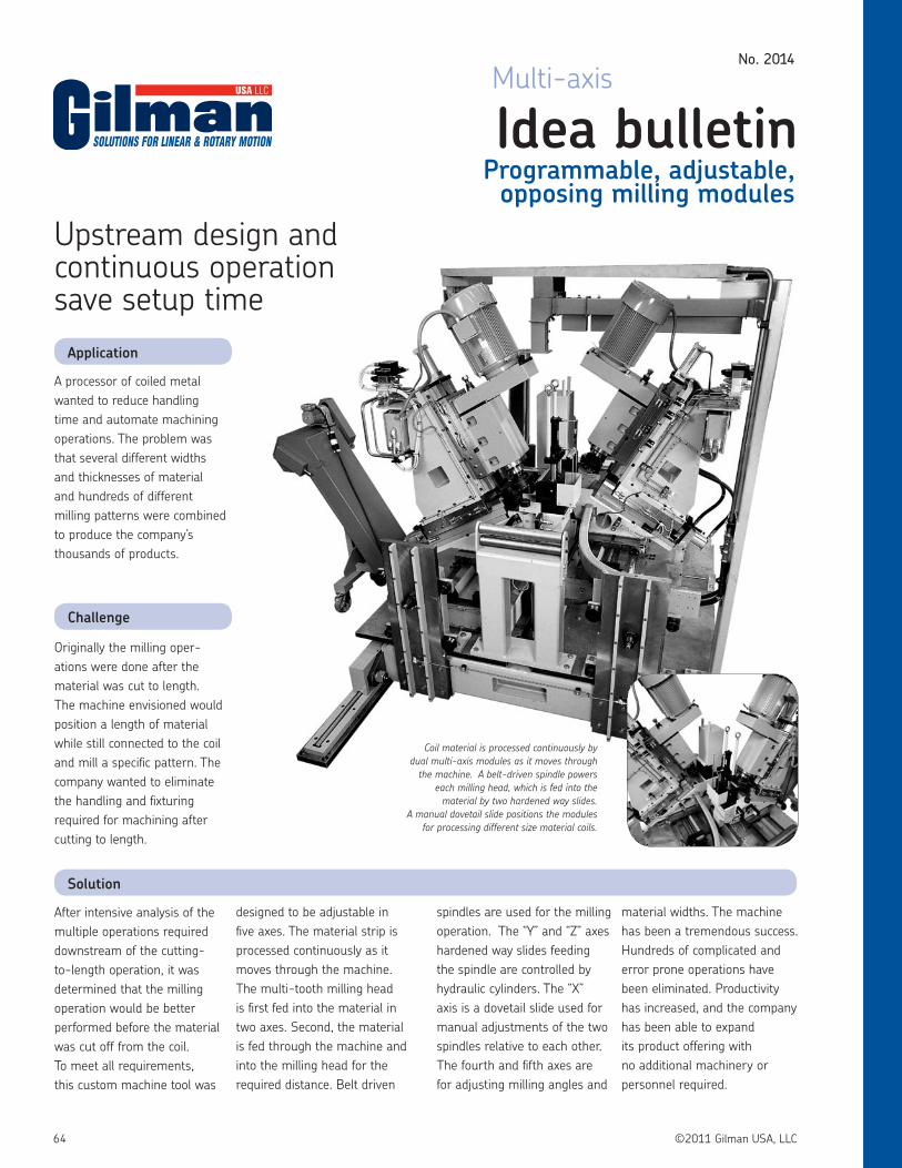
64 ©2011 Gilman USA, LLC
A processor of coiled metal wanted to reduce handling time and automate machining operations. The problem was that several different widths and thicknesses of material and hundreds of different milling patterns were combined to produce the company’s thousands of products.
Originally the milling oper-ations were done after the material was cut to length. The machine envisioned would position a length of material while still connected to the coil and mill a specific pattern. The company wanted to eliminate the handling and fixturing required for machining after cutting to length.
Application
Challenge
Solution
Idea bulletinProgrammable, adjustable,
opposing milling modules
No. 2014
Multi-axis
Upstream design and continuous operation save setup time
After intensive analysis of the multiple operations required downstream of the cutting-to-length operation, it was determined that the milling operation would be better performed before the material was cut off from the coil. To meet all requirements, this custom machine tool was
designed to be adjustable in five axes. The material strip is processed continuously as it moves through the machine. The multi-tooth milling head is first fed into the material in two axes. Second, the material is fed through the machine and into the milling head for the required distance. Belt driven
spindles are used for the milling operation. The “Y” and “Z” axes hardened way slides feeding the spindle are controlled by hydraulic cylinders. The “X” axis is a dovetail slide used for manual adjustments of the two spindles relative to each other. The fourth and fifth axes are for adjusting milling angles and
material widths. The machine has been a tremendous success. Hundreds of complicated and error prone operations have been eliminated. Productivity has increased, and the company has been able to expand its product offering with no additional machinery or personnel required.
Coil material is processed continuously by dual multi-axis modules as it moves through
the machine. A belt-driven spindle powers each milling head, which is fed into the
material by two hardened way slides. A manual dovetail slide positions the modules
for processing different size material coils.

65©2011 Gilman USA, LLC
Not only is the design and operation of the machine successful, but the Gilman components that made it possible are all stock or standard products. This use of existing designs kept the project cost low.
• 2 each HWS12-12-21-H2-3 slide assembly with hydraulic cylinder drive
• 2 each HWL12-22-30-H3-5 slide assembly with hydraulic cylinder drive
• 2 each DC16-19-36-M-E1-15 slide assembly with Acme screw with right angle hand wheel
• 2 each 6500C-X2M-50-SB3 belt-driven, motorized spindle
• The customer provided the angle brackets and assembled the machine on their shop floor.
By using stock and standard components to achieve the customer’s design goals, cost and delivery time were both minimized.
No. 2014
All dimensions in inches unless otherwise indicated.
Technical specifications
Cost savings Sales point
87.5
0
56.25 60.00
HWS12-12-21-H2-3
HWL12-12-21-H2-3
6500C-X2M-50-SB3
DC16-19-36-M-E1-15
5" STROKEZ AXIS
Single Milling Module Illustrated
15" X AXIS
3" STROKEY AXIS
Side view Front view

66 ©2011 Gilman USA, LLC
There are a lot of things that a job shop can do to improve the performance of a machining tool spindle. From predicting spindle replacement to taking advantage of new high-speed tooling, spin-dle enhancements can increase uptime and improve performance. The following suggestions come from Chris Hetzer, Vice President of Engineering, Gilman USA (formerly Russell T. Gilman, Inc.).
Monitor that spindleInstalling a spindle monitoring and recording unit (SMRU) helps keep track of critical maintenance issues. Maintenance of spindles is hard to predict because they are designed to work in a certain temperature range for a certain period in time. For example, when operated at 15°C above normal, grease-life decreases by a factor of two. SMRUs record temperature, speed and running hours. In one brand of these units, the Gilman USA iSpindle SMRU, the information is stored in a histogram form which pro-vides the maintenance engineer with information to assess how long the spindle has been running and to make a prediction of the remaining grease-life. The unit can be integrated into the spindle or bolted to it. A maximum of 255 uniquely addressable units can be connected to a wireless wide area network. PC software is available for configuration of the SMRU’s identification, recording settings, user comments, real-time display of temperatures and speed information and database storage in MS Word or HTML.
Ceramics are coolConsider replacing a spindle’s bearings with hybrid ceramic bear-ings. On a grinder, 25 percent higher RPM can be achieved by replacing steel ball bearings using oil/air-mist running at 10,000 to 15,000 RPM with hybrid ceramic bearings and synthetic grease lubricant. Grinding spindles with hybrid ceramics spindles may run 4,000 hours without problems, compared to 3,000 hours with steel bearings. Gilman USA reports running hybrid bearings up to 5,000 hours at speeds exceeding 2.0 million ndm before part degradation occurs. (Ndm is the bearing pitch diameter in millimeters multiplied by RPM, a value that compares the relative performance of bearings of different sizes.) Some steel bearings quit after 700 hours. Hybrid ceramic bearings can lower tempera-tures nearly 50 percent and last as many as seven times longer than steel bearings. In a horizontal ram-type machining center, switching from steel to hybrid bearings has been shown to drop bearing temperature from 60°C to 36°C at 12,000 RPM.
Belt drives can be hip, tooConventional belt-driven spindles, which use a pair of angular contact bearings at the belt-drive end, may have problems with spindle deflection and premature failures. At high speeds, the belt pull loads the bearings radially and also restricts the axial move-ment of the bearings to compensate for the thermal growth of the spindle system. In a typical hybrid ceramic roller bearing upgrade for a 40-taper vertical machining spindle operating at 15,000 rpm, the rear bearing set is a single row, hybrid ceramic roller bearing with a composite plastic cage, while the front bear-ings may be triplex angular contact hybrid ceramic ball bearings such as Gilman USA 71914ACD/P4ATBA. Lubrication is synthetic grease. The hybrid ceramic roller bearing offers twice the radial ri-gidity than the original angular contact set and allows for smooth
shaft thermal elongation. The entire spindle system is more rigid, which allows for a higher first flexural critical speed. The operating performance of the cylindrical roller bearing with grease may be as high as 1,162,500 ndm at an operating temperature of 36°C.
Shielded is fasterUpgrading to shielded ball bearings can eliminate the need for air purge or spot oil lubrication while reducing contamination and al-lowing increased spindle speed. Standard shielded bearings have the same internal geometry, ball diameter, speed rating, load rat-ings, preload classes, matching criteria and contact angles as the bearings they replace. Double-shielded bearings are dependent solely upon the pre-packed lubricant of the bearing. An Gilman USA high- speed double-shielded design incorporates smaller di-ameter rolling elements, the rings have been designed with open conformities for high-speed performance. This design has higher speed capability but lower load ratings than the corresponding size of the CD/ACD bearing. These high speed shielded grease bearings will run faster than spot oil lubricated standard bearings.
Let the “Force” seal itGilman USA’s air seals use an air distribution ring and a rotating metal cased elastic sealing member combining the advantages of contact seals and air purge. The elastic sealing member slightly lifts from the contact surface as the spindle rotation increases the centrifugal force. The metal case slings away any oncoming contaminants. The air-distribution ring allows for uniform airflow, which ensures that the seal will ride on a thin film of air while rotating. The air also pushes contaminants away from the spindle. In a static condition the elastic seal provides a positive contact by keeping contaminants from entering the spindle. The result is a highly effective seal.
HSK means high speed “Kapacity”The German translation of HSK literally means “hollow taper shank,” but upgrading the spindle to HSK tooling will improve ri-gidity and high-speed machining performance. HSK tooling allows deeper cuts and higher feed rates in milling and boring opera-tions. HSK has metal-to-metal contact both radially and axially. The radial stiffness of HSK tool holders is up to five times greater than CAT, SK or BT. In the axial direction, the accuracy of a CAT (SK, BT) connection can vary as much as 0.004 inches compared to an HSK shank. HSK is not subject to bell-mouthing of the machine spindle, which occurs as a result of wear. It also has a higher natural frequency allowing higher speeds before chatter. HSK tooling transfers significantly greater torque and is more resistant to pullout forces. The tool-changing capability of HSK is faster than steep-taper shanks because of the short length of the HSK taper and the lighter weight of its hollow shank. The HSK connection prevents the shank from pulling back into the receiver during high-speed operation, changing the Z-axis position.
Scanning the horizon for enhanced spindle performancePreviously published in Modern Machine Shop June 2002

67©2011 Gilman USA, LLC
Gilman USA serves a broad cross section of the world’s lead-ing companies with a constantly evolving product line and engineering capabilities.
You are invited to further explore the benefits of a partner-ship with Gilman USA as your preferred supplier of precision machine tool components by touring our facilities. Gilman USA’s Spindle Service Centers provides complete remanu-facturing services for conventional spindles and special applications.
Gilman USA is part of the world’s largest bearing and lin-ear motion component supplier. The U.S.-based Gilman USA
Gilman USA spindle network offers solutions for machine tool builders and users worldwide
For complete catalogs, selected budgetary pricing, engineering data and downloadable DWG and DXF files to place in your CAD drawings, visit www.GilmanUSA.com
Bearing Service Center provides unique bearing and preload configurations. In addition to Gilman USA’s Spindle Service Center in Grafton, WI, Spindle Service Centers are located in Gothenburg, Sweden; Schweinfurt, Germany; Steyr, Austria; Chino, Japan; Luton, UK; Ozoir, France; Torino, Italy; São Paulo, Brazil; Moscow, Russia; and Chinchwad, India. Gilman USA also offers an Engineering Resource Center (Gilman USA ERC) for developing new bearings, lubrication technol-ogy and future applications. For more information and the name of the Gilman USA representative in your area, please call, write, fax or visit our web site.

The contents of this publication are the copyright of the publisher and may not be reproduced (even extracts) unless prior written permission is granted.Every care has been taken to ensure the accuracy of the information contained in this publication but no liability can be accepted for any loss or damage whether direct, indirect or consequential arising out of use of the information contained herein.©2011 Gilman USA, LLCVersion 12/2011 Printed in U.S.A.
Gilman USA, LLC1230 Cheyenne AvenueP.O. Box 5Grafton, WI 53204Telephone: 800-445-6267 or 262-204-2227Fax: 262-377-9438e-mail: [email protected]