carlos vega rework done-2
TRANSCRIPT
8/7/2019 Carlos Vega Rework Done-2
http://slidepdf.com/reader/full/carlos-vega-rework-done-2 1/12
8/7/2019 Carlos Vega Rework Done-2
http://slidepdf.com/reader/full/carlos-vega-rework-done-2 2/12
Usually there are six stands for the finishing tandem mill, the first three stand are used
call beginnings stand and the last three ones as finishing stand; these mills have four
rolls, two of them are the work rolls and are in direct contact with the strip; being the
steel within a range of 1000 ºC at the mill entry and 800 ºC at the mill exit, and twobackup rolls, these ones having contact with the work rolls.
Pressure applied by the rolls on the slab results in a reduction of 203.2 mm and up to
1.8 mm, according to the customer specification. However, this process is one of the
most expensive ones for the steelmaking industry due to the elements this process
consist on [Ohkomori, 1988].
Hot rolling campaigns of the backup rolls are very long. The wear produced by the
mechanical contact with the work roll, and the temperature and the pressure exerted on
the roll work body as well.
1.1 Wear on rolls for hot strip rolling
Rolls are subjected to a large work volumes, and extreme temperatures as well, and
obviously they require a great strength against cracks and flaws [J.A Schey, 1983].
Considering that the rolls are the most expensive input in the rolling process, it is
important to define what is causing the roll wear, and taking into account the
aforementioned, it becomes relevant to be specific answering the following question, How the
wear of the rolls is generated in the Hot Rolling process? [Chausevich, 1983].
Mechanical properties required by the hot rolling rolls vary, depending on the process
stage in the rolling line; while at the beginning usually the dominant variables are the
high temperature strength and the toughness of the material, at the downstream stages
the abrasion wear strength becomes the most important wear factor; the yield is not
well defined yet, because there are several influence factors, such as mass or hot
rolled strip length produced per millimeters of material used or total of processed
product tons per roll kit per rolling schedule [S. Spuzic, 1994].
1.2 Types of wear on the rolls
Experience has demonstrated that the wear increases quickly after producing a specific
amount of rolled steel; therefore roll change shall be done after some specific
production in order to prevent a catastrophic wear [S. Spuzic, 1994], for that reason it is
needed to identify the processes which are wearing out these elements, which are
cited below:Abrasion: This element is one of the governing components; it is included in the total
of the wear during the process [Ginzburg, 1989]. Having a presence as scales of high
hardness oxide and low elasticity on the hot steel surface, we can usually think of
abrasion as two or three wear bodies [S.E Lundberg, 1993] [Gahr, 1987]. We may
expect that the roll deterioration be important, because micro-cuts, micro-fatigue and
micro-cracks are formed, which will damage the rolled steel quality [Ginzburg, 1989],
and this wear depends on the shape and hardness of the abrasive particles, producing
deformations, originated by a micro-cut or elasticity on the surface and in the inside
layers of the roll by the contact, resulting as a consequence, the formation of cracks
[Jahanmir, 1981].
2
8/7/2019 Carlos Vega Rework Done-2
http://slidepdf.com/reader/full/carlos-vega-rework-done-2 3/12
8/7/2019 Carlos Vega Rework Done-2
http://slidepdf.com/reader/full/carlos-vega-rework-done-2 4/12
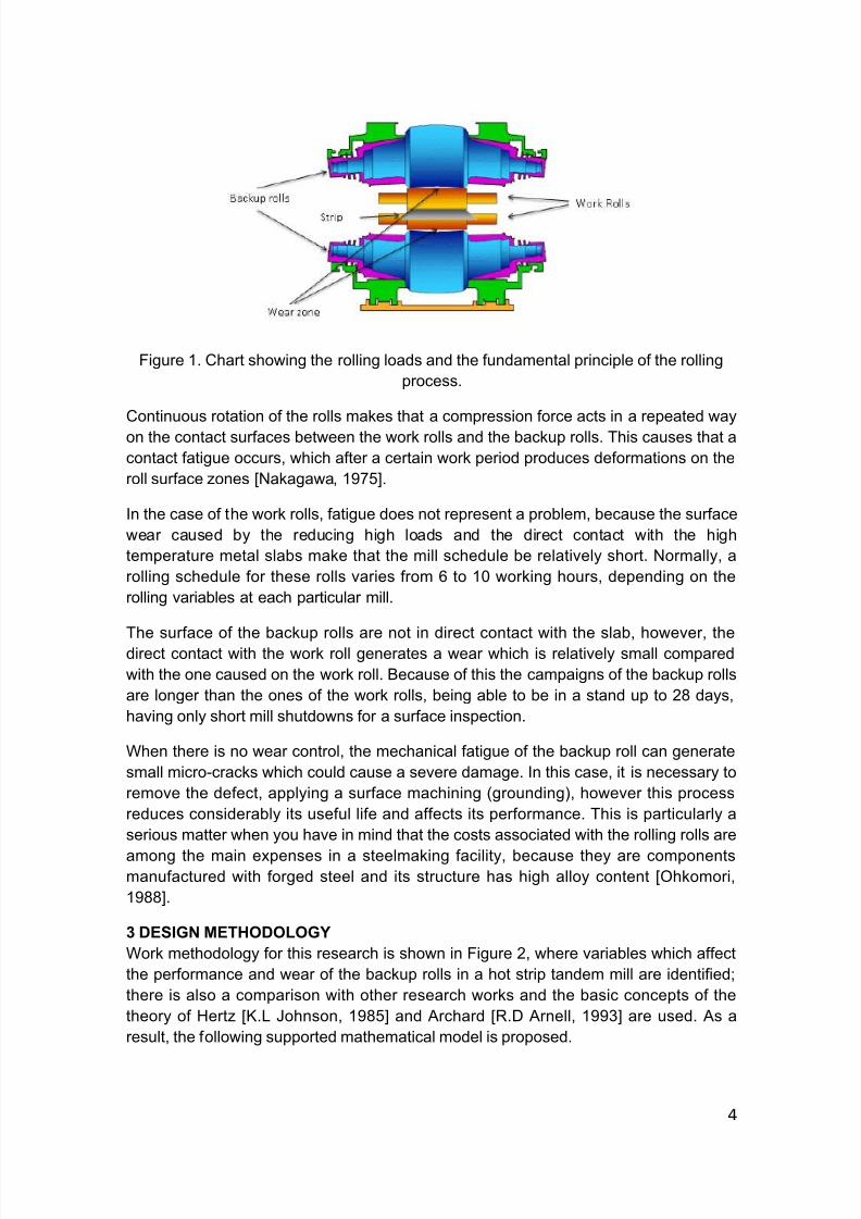
Figure 1. Chart showing the rolling loads and the fundamental principle of the rolling
process.
Continuous rotation of the rolls makes that a compression force acts in a repeated way
on the contact surfaces between the work rolls and the backup rolls. This causes that a
contact fatigue occurs, which after a certain work period produces deformations on the
roll surface zones [Nakagawa, 1975].
In the case of the work rolls, fatigue does not represent a problem, because the surface
wear caused by the reducing high loads and the direct contact with the high
temperature metal slabs make that the mill schedule be relatively short. Normally, a
rolling schedule for these rolls varies from 6 to 10 working hours, depending on the
rolling variables at each particular mill.
The surface of the backup rolls are not in direct contact with the slab, however, thedirect contact with the work roll generates a wear which is relatively small compared
with the one caused on the work roll. Because of this the campaigns of the backup rolls
are longer than the ones of the work rolls, being able to be in a stand up to 28 days,
having only short mill shutdowns for a surface inspection.
When there is no wear control, the mechanical fatigue of the backup roll can generate
small micro-cracks which could cause a severe damage. In this case, it is necessary to
remove the defect, applying a surface machining (grounding), however this process
reduces considerably its useful life and affects its performance. This is particularly a
serious matter when you have in mind that the costs associated with the rolling rolls are
among the main expenses in a steelmaking facility, because they are componentsmanufactured with forged steel and its structure has high alloy content [Ohkomori,
1988].
3 DESIGN METHODOLOGY
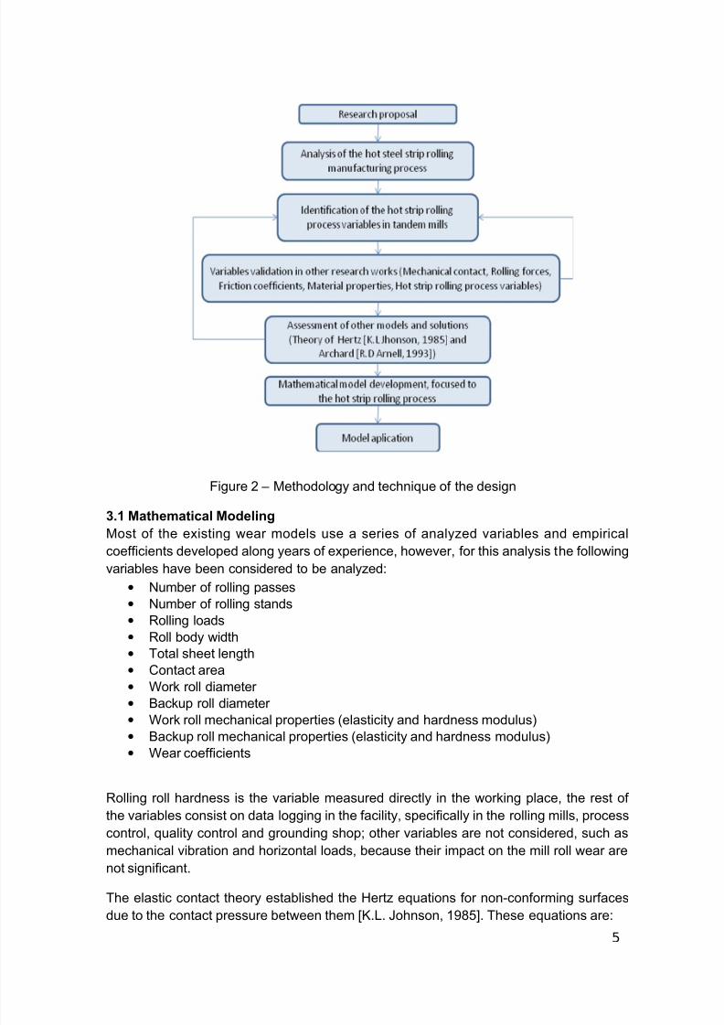
Work methodology for this research is shown in Figure 2, where variables which affect
the performance and wear of the backup rolls in a hot strip tandem mill are identified;
there is also a comparison with other research works and the basic concepts of the
theory of Hertz [K.L Johnson, 1985] and Archard [R.D Arnell, 1993] are used. As a
result, the following supported mathematical model is proposed.
4
8/7/2019 Carlos Vega Rework Done-2
http://slidepdf.com/reader/full/carlos-vega-rework-done-2 5/12
Figure 2 – Methodology and technique of the design
3.1 Mathematical Modeling
Most of the existing wear models use a series of analyzed variables and empiricalcoefficients developed along years of experience, however, for this analysis the following
variables have been considered to be analyzed:
• Number of rolling passes
• Number of rolling stands
• Rolling loads
• Roll body width
• Total sheet length
• Contact area
• Work roll diameter
• Backup roll diameter
• Work roll mechanical properties (elasticity and hardness modulus)• Backup roll mechanical properties (elasticity and hardness modulus)
• Wear coefficients
Rolling roll hardness is the variable measured directly in the working place, the rest of
the variables consist on data logging in the facility, specifically in the rolling mills, process
control, quality control and grounding shop; other variables are not considered, such as
mechanical vibration and horizontal loads, because their impact on the mill roll wear are
not significant.
The elastic contact theory established the Hertz equations for non-conforming surfacesdue to the contact pressure between them [K.L. Johnson, 1985]. These equations are:
5
8/7/2019 Carlos Vega Rework Done-2
http://slidepdf.com/reader/full/carlos-vega-rework-done-2 6/12
3
1
*4
3
=E
PRa (1)
3
1
23
2*
20
6
2
3
==
R
PE
a
P P
π π
(2)
where:
a = Contact arc length
P = Normal load
R = Relative curvature radius
*E = Effective elastic modulus
0P
= Maximum pressure
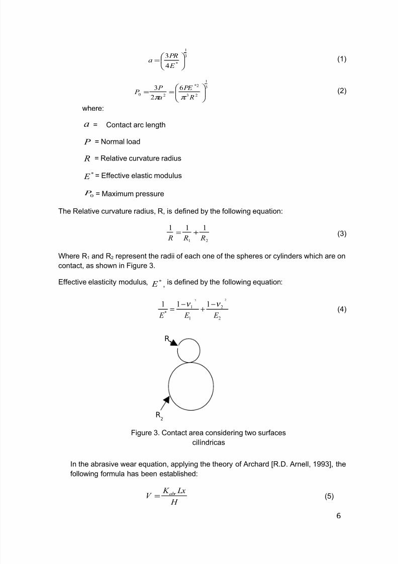
The Relative curvature radius, R, is defined by the following equation:
21
111
RRR+= (3)
Where R1 and R2 represent the radii of each one of the spheres or cylinders which are on
contact, as shown in Figure 3.
Effective elasticity modulus, *E , is defined by the following equation:
2
2
1
1
*
22
111
E E E
ν ν −+
−= (4)
In the abrasive wear equation, applying the theory of Archard [R.D. Arnell, 1993], the
following formula has been established:
H
LxK V abr = (5)
6
R2
R1
Figure 3. Contact area considering two surfaces
cilíndricas
8/7/2019 Carlos Vega Rework Done-2
http://slidepdf.com/reader/full/carlos-vega-rework-done-2 7/12
where:
V = Removed material volume
abr K = Abrasive wear coefficient
L = Applied load
x = Traveled distance
H = Hardness ratio
If equation (5) is applied to the rolling process, removed material volume from the roll
is the worn material and it is equal to the contact area between both rolls times the
worn height, Ah . Applying this principle, and solving the formula for the worn
material height h , the formula shall be as follows:
HA
LxK h
abr =
(6)
Considering thatA
Lrepresents the pressure of a load on a given area, 0
P can be
replaced in the equation (6), considering that we are looking for the maximum contact
pressure; thus, equation (6) shall be as follows:
H
xP K h
abr 0=
(7)
Replacing equation (2) in equation (7), the formula shall be as follows:
H
xR
PE K
H
xR
PE K
h
abr abr
3
1
22
2*3
1
23
2*66
=
=π π π
(8)
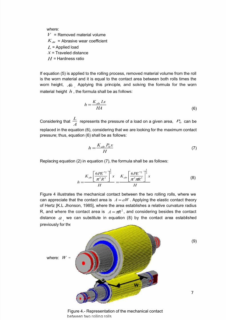
Figure 4 illustrates the mechanical contact between the two rolling rolls, where we
can appreciate that the contact area is aW A = . Applying the elastic contact theory
of Hertz [K.L Jhonson, 1985], where the area establishes a relative curvature radius
R, and where the contact area is 2RA π = , and considering besides the contact
distance a , we can substitute in equation (8) by the contact area established
previously for the rolling process, resulting the following equation:
H
xaW
PE K
h
abr
3
1
2
2*6
=π
(9)
where: =W Roll body width and =a Contact arc
7
Figure 4.- Representation of the mechanical contact
aW
8/7/2019 Carlos Vega Rework Done-2
http://slidepdf.com/reader/full/carlos-vega-rework-done-2 8/12
D
DL
aW
PE K
abr
13
1
2
2*6
π
Rolling process is a process where the higher hardness material is rotating and
the basic equation of wear was generated from a model where the hard material is
moving along a straight line but without turning, therefore, in order to develop the
model, equation (9) shall be multiplied times a factor that associates the contact arc
between the two cylinders, where D1 is the diameter for the work roll and D2 the
diameter for the backup roll, which is2
1
D
D, in such a way that the equation (9) shall
be as follows:
(10)
Considering that the total length of the strip identified as L is equivalent to the
traveled distance x , and applying, in the contact area of the two rolls, the same
criteria used to develop the equation in the contact area of the slab with the rolls, the
equation (10) shall be as follows:
(11)
Unit value of the height the rolling roll is worn per each processed slab can be
calculated with the equation (11), however, a rolling campaign consist on several
rolled slabs, changing according to the production program; so, the total value of the
wear per rolling campaign corresponds to a summation of values accumulating the
wears from the first slab and up to an indefinite number of slabs, n , therefore, the
final equation of the mathematical model would result as follows:
8
H
D
Dx
aW
PE K
h
abr
2
13
1
2
2*6
=π
8/7/2019 Carlos Vega Rework Done-2
http://slidepdf.com/reader/full/carlos-vega-rework-done-2 9/12
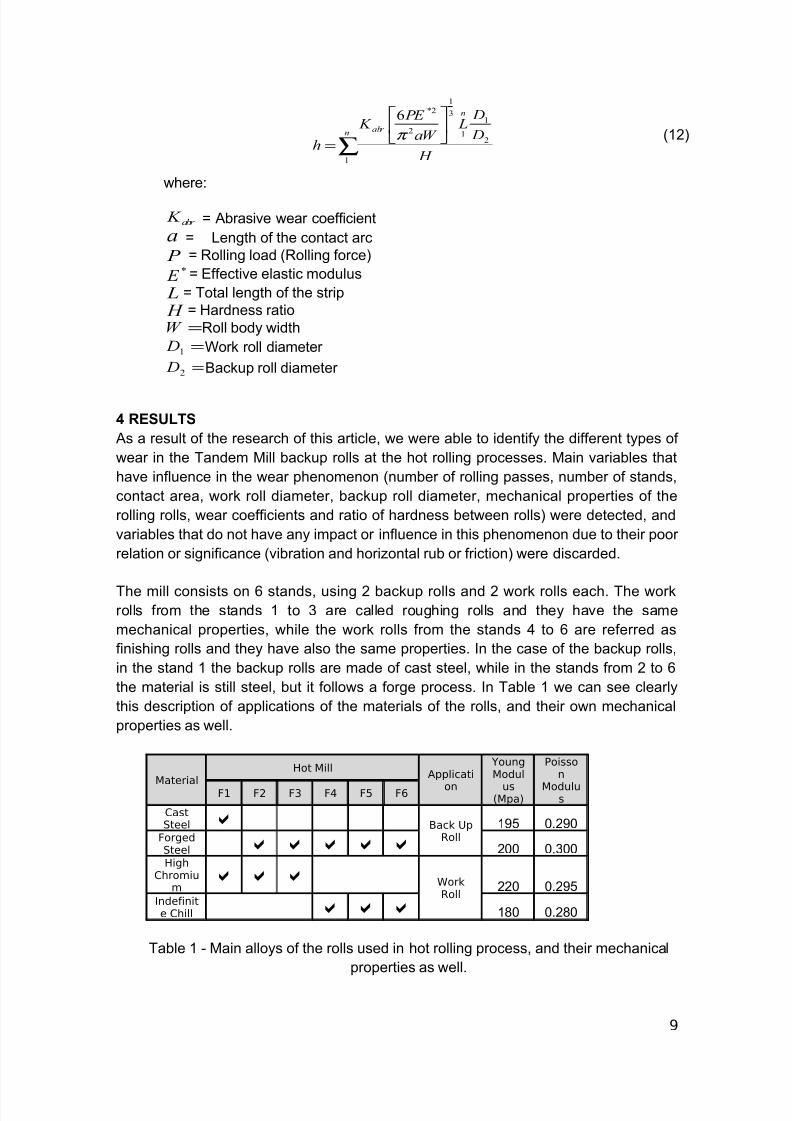
(12)
where:
abr K = Abrasive wear coefficient
a = Length of the contact arc
P = Rolling load (Rolling force)*
E = Effective elastic modulus
L = Total length of the strip
H = Hardness ratio
=W Roll body width
=1
D Work roll diameter
=2
D Backup roll diameter
4 RESULTS
As a result of the research of this article, we were able to identify the different types of
wear in the Tandem Mill backup rolls at the hot rolling processes. Main variables that
have influence in the wear phenomenon (number of rolling passes, number of stands,
contact area, work roll diameter, backup roll diameter, mechanical properties of the
rolling rolls, wear coefficients and ratio of hardness between rolls) were detected, and
variables that do not have any impact or influence in this phenomenon due to their poor
relation or significance (vibration and horizontal rub or friction) were discarded.
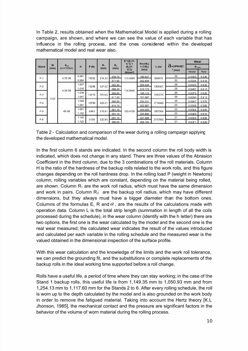
The mill consists on 6 stands, using 2 backup rolls and 2 work rolls each. The workrolls from the stands 1 to 3 are called roughing rolls and they have the same
mechanical properties, while the work rolls from the stands 4 to 6 are referred as
finishing rolls and they have also the same properties. In the case of the backup rolls,
in the stand 1 the backup rolls are made of cast steel, while in the stands from 2 to 6
the material is still steel, but it follows a forge process. In Table 1 we can see clearly
this description of applications of the materials of the rolls, and their own mechanical
properties as well.
Material
Hot MillApplicati
on
YoungModul
us(Mpa)
Poisson
Modulus
F1 F2 F3 F4 F5 F6
CastSteel Back Up
Roll195 0.290
ForgedSteel 200 0.300High
Chromium
Work
Roll220 0.295
Indefinite Chill 180 0.280
Table 1 - Main alloys of the rolls used in hot rolling process, and their mechanical
properties as well.
9
∑
=n
n
abr
H
D
DL
aW
PE K
h
1
2
1
1
3
1
2
2*6
π
8/7/2019 Carlos Vega Rework Done-2
http://slidepdf.com/reader/full/carlos-vega-rework-done-2 10/12
8/7/2019 Carlos Vega Rework Done-2
http://slidepdf.com/reader/full/carlos-vega-rework-done-2 11/12
The methodology and the design technique for the making of the mathematical model
was a suitable one, because it enables us to verify the variables used in other
researches using the Archard theory [R.D Arnell, 1993] in order to apply it to the rolling
process, allowing us to understand the behavior of other models and the existing
solutions related to this subject of material removed by contact between materials and
wear.
In the making of the model, it was considered that during the rolling process, the harder
the material the higher the wear produced in the rest of the materials, this same
situation is found in relation with the contact arc between the rolls, that is why the ratio
of temperatures and the hardness of the rolls is taken in the field, in order to consider
the warm-up experienced by the rolling rolls due to the influence of the heat
transference provided by the slab.
The model establishes the total value of the wear during the whole rolling cycle or
schedule, considering the summing up of the accumulated values of the wears for thewhole number of used (rolled) slabs. This wear ratio during all the rolling process is
directly related to the mechanical fatigue of the backup rolls, which at a certain level of
overload may generate micro-cracks that affect the strip production process.
5 DISCUSSION
Mathematical Model use is a fundamental tool in prediction making in production
processes. In this particular case of hot steel lamination where support rolls are
submited to strong workloads, consideration of all variables involved in its opreation
and wear is very important. This investigation only consider variables described in the
proposed mathematical model formulation at the begining of this text, which are ones
that impact support rolls wear process huge. It is relevant to consider accumulative
wear in each lamination campaign according to order production specifications.
6 CONCLUSIONS
Operational variables in the hot rolling process depend on the stand number, e.g. in the
roughing stands, strip reduction percentages are higher, requiring larger rolling forces,
even when the strip temperature is higher and there is higher plasticity. This variation
can also be observed in the calculation of the variables considered in the mathematical
model, therefore is coherent to think that the wear value obtained at the end of the
rolling schedule will have a variation among the different mill stands; this hypothesis
can be verified with the results obtained in Table 1.
The developed mathematical model allows to know and assess the performance of the
rolls at the mill, to make a prediction of the wear, and in this manner to make suitable
decisions for the right equipment operation, preventing finished product rework
because of the quality, or damaging the equipment and tooling, which are attributed to
accidents caused by excessive wear in the rolling rolls.
This mathematical model describes in precision support roll wear process behavior andoffers total amount in milimeters of wear at the end of a lamination campaign in each
11
8/7/2019 Carlos Vega Rework Done-2
http://slidepdf.com/reader/full/carlos-vega-rework-done-2 12/12
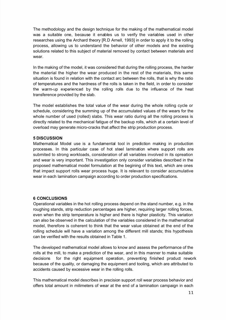
support roll. As we can see in table 2, changes in values of variables considered in this
model have effect in roll wear calculations.
By calculating wear amount suffered in support rolls, we are offering an alternative in
maximizing total life cicle of this rolls.
As a future work the authors pretend to use the model with computational algorithms to
calibrate and improve the precision of the results.
REFERENCES.
[1] R.D. Arnell, P.B Davies, J. Halling, T.L Whomes, Tribology, Principles and DesignApplications, [M] The Macmillan Press Ltd., Springer – Verlag Nueva York, EstadosUnidos de America, 1993, p. 54 and 71.[2] M. Chausevich, Rolling of Metallic Materials, [J] Veselin Maslesa, Sarajevo, 1983,30, p1-2.[3] R.B. Corbett, Rolls for the Metalworking Industries, [M] Iron and Steel Society,
Warrendale, PA, 1990, p. 273.[4] V.B. Ginzburg, Steel Rolling Technology, Theory and Practice, [M] Marcel Dekker,New York, 1989, p. 505.[5] S.Jahanmir, in N.P. suh (ed.). Fundamentals of tribology Proc. Int. Conf., [M] MITPress, London, United Kingdom, 1981, p. 455.[6] K.L Johnson. Contact Mechanics. [M] Cambridge University Press, Cambridge,United Kingdom, 1985, p.36-53.[7] S.E. Lundberg, The Influence of rolling temperature on roll wear, [J] Journal of Materials Processing Technology, Elsevier Amsterdam, Netherlands,1993, 36, p 273.[8] Nakagawa M.A, Consideration and decision of suitable regrinding amount of back-up roll for 4-High mills, [J] Hitachi Review, 1975, 33, p 467-472[9] Ohkomori, Cause end prevention of spalling of backup rolls for hot strip mill, [J]
Transactions of the ISIJ, 1988, v. 28, n. 1, p. 4[10] J.A Schey, Tribology in Metalworking – Friction, Lubrication and Wear, [M]American Society for Metals, Metals Park, OH, 1983, p.249 and 312.[11] A. Suarez, J. Velez, Study on wear proposed by Archard, [J] Redalyc, 2005, 72, P28[12] S. Spuzic, Wear of hot rolling mill rolls: an overview, [J] Elsevier, Amsterdam,Netherlands, 1994, 176, p 264.[13] R. V. Williams and G.M. Boxall, Deterioration in hot strip mills, [J] Journal of theIron & Steel Institute, 1965, 203, p 369–377[14] K- H Zum Gahr, Microstructure and Wear of Materials, [J] Elsevier, AmsterdamNetherlands, 1987, 90, P 253-261
12