cardiovascular test methods: part iii current … documents/standards...• include reference and...
TRANSCRIPT
Kenneth E. Perry, Ph.D.ECHOBIO LLC
Bainbridge Island, WA
PERU Workshop on Medical Device Regulation:Policy and Technical Aspects
Cardiovascular Test Methods: Part IIICurrent Issues in Materials and Testing
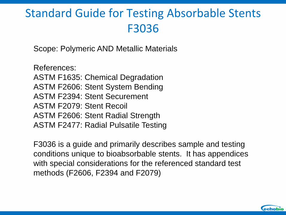
Scope: Polymeric AND Metallic Materials
References:ASTM F1635: Chemical DegradationASTM F2606: Stent System BendingASTM F2394: Stent SecurementASTM F2079: Stent RecoilASTM F2606: Stent Radial StrengthASTM F2477: Radial Pulsatile Testing
F3036 is a guide and primarily describes sample and testing conditions unique to bioabsorbable stents. It has appendices with special considerations for the referenced standard test methods (F2606, F2394 and F2079)
Standard Guide for Testing Absorbable StentsF3036

Scope: Polymeric AND Metallic Materials
The scope for F3036 does not exclude metallic absorbable stents, HOWEVER, there are no current test methods available for these materials.
The issue: There was not consensus in the industry about the mechanisms of degradation, in vitro or in in vivo when the standard was written. Specifically, There was not agreement on the best degredation media to use for testing metallic absorbable materials in vitro. Therefore, the best test methods and procedures could not be determined.
Standard Guide for Testing Absorbable StentsF3036
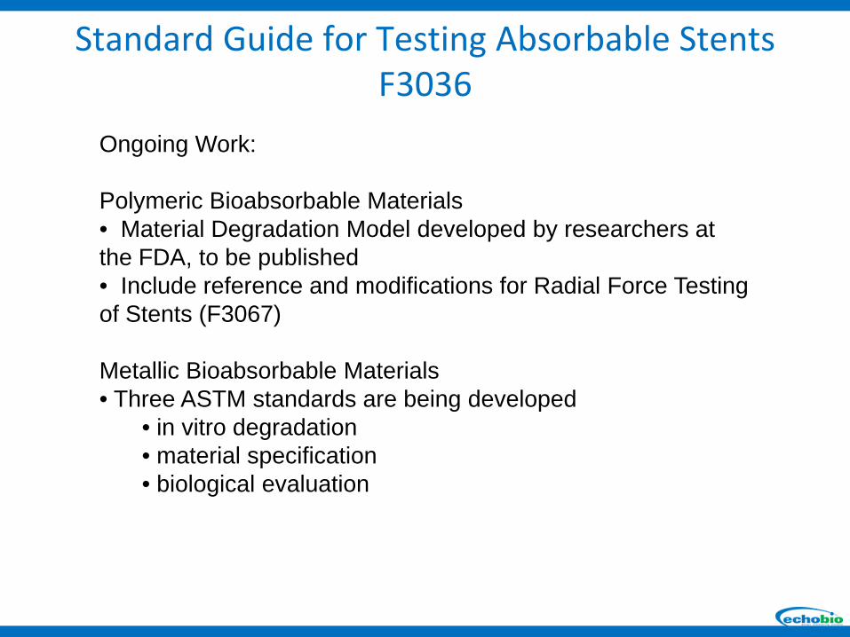
Ongoing Work:
Polymeric Bioabsorbable Materials• Material Degradation Model developed by researchers at the FDA, to be published• Include reference and modifications for Radial Force Testing of Stents (F3067)
Metallic Bioabsorbable Materials• Three ASTM standards are being developed
• in vitro degradation• material specification• biological evaluation
Standard Guide for Testing Absorbable StentsF3036
Do we learn more by testing a few devices to survive a limited set of
loading conditions?OR
Do we learn more by testing lots of samples to fracture and modeling
the device under all anticipated loading conditions?
Test to Success versus Test to Fracture

Committee members participated in a round robin study of a generic balloon expandable stent.
300 stents were designed, manufactured and distributed to participating labs.
Objective of inter-laboratory testing study:Perform Axial Fatigue testing of one design at multiple load levels. Compare results from independent labs.
Objective of computational modeling study:FE and Fatigue analysis of 316 L SS stent in Axial Fatigue. Predict expected life for multiple load levels.
ASTM F04.30.06Fatigue to Fracture Round Robin Study
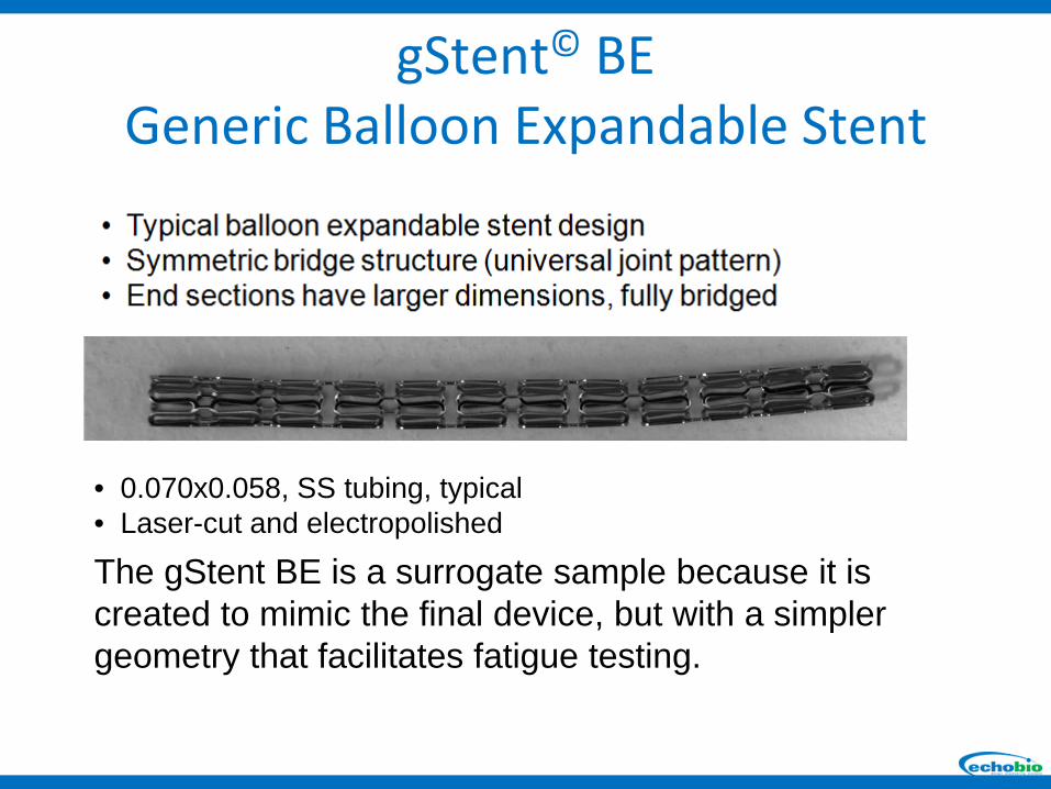
• 0.070x0.058, SS tubing, typical• Laser-cut and electropolished
The gStent BE is a surrogate sample because it is created to mimic the final device, but with a simpler geometry that facilitates fatigue testing.
gStent© BEGeneric Balloon Expandable Stent
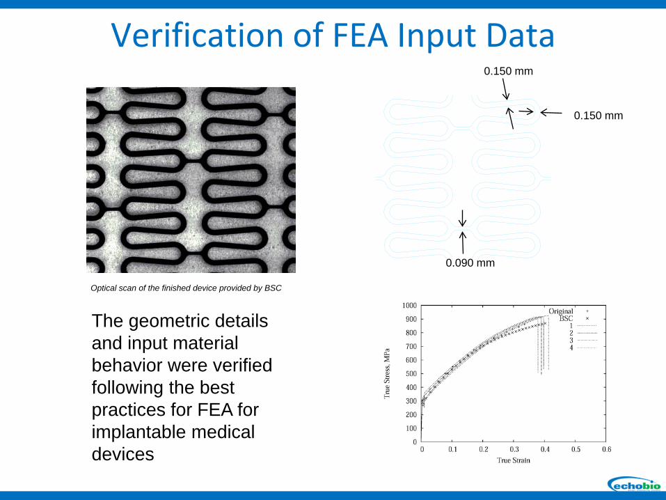
Optical scan of the finished device provided by BSC
0.150 mm
0.090 mm
0.150 mm
The geometric details and input material behavior were verified following the best practices for FEA for implantable medical devices
Verification of FEA Input Data
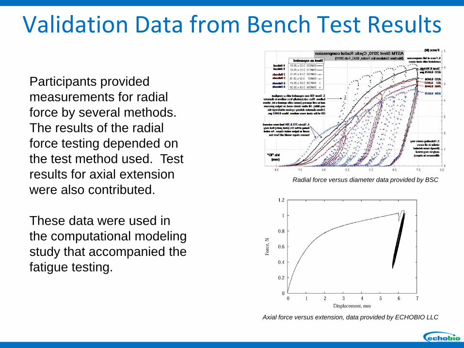
Axial force versus extension, data provided by ECHOBIO LLC
Radial force versus diameter data provided by BSC
Participants provided measurements for radial force by several methods. The results of the radial force testing depended on the test method used. Test results for axial extension were also contributed.
These data were used in the computational modeling study that accompanied the fatigue testing.
Validation Data from Bench Test Results

Expansion Stresses
Peak Stresses After Recoil
Computational modeling results were compared between the labs.
Differences between various FEA software, analysis parameters and methodologies were identified and understood.
Peak stress results according to the various labs are shown.
Inter-laboratory Computational Model Study

Stent images provided by BSC
Computational models suggested that material plasticity during balloon catheter expansion could affect the fatigue property.
Identical catheters were distributed to insure that all stents received equal expansion before fatigue testing.
The most uniform expansion was achieved with non-compliant balloons.
Consistent Loading History Observed
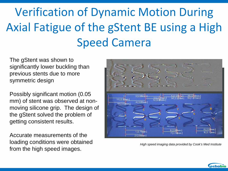
The gStent was shown to significantly lower buckling than previous stents due to more symmetric design
Possibly significant motion (0.05 mm) of stent was observed at non-moving silicone grip. The design of the gStent solved the problem of getting consistent results.
Accurate measurements of the loading conditions were obtained from the high speed images.
High speed imaging data provided by Cook’s Med Institute
Verification of Dynamic Motion During Axial Fatigue of the gStent BE using a High
Speed Camera
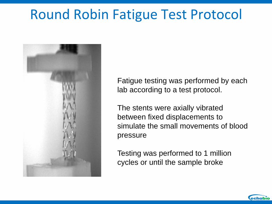
Fatigue testing was performed by each lab according to a test protocol.
The stents were axially vibrated between fixed displacements to simulate the small movements of blood pressure
Testing was performed to 1 million cycles or until the sample broke
Round Robin Fatigue Test Protocol
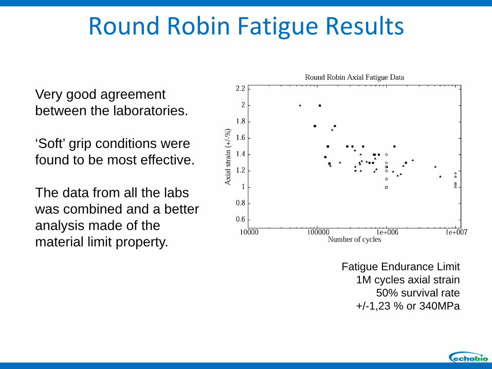
Fatigue Endurance Limit1M cycles axial strain
50% survival rate+/-1,23 % or 340MPa
Very good agreement between the laboratories.
‘Soft’ grip conditions were found to be most effective.
The data from all the labs was combined and a better analysis made of the material limit property.
Round Robin Fatigue Results

All of the fractures in the study occurred in the gage sections of the sample
This is good news because it means the test article performed as it was intended.
Round Robin Fatigue Results
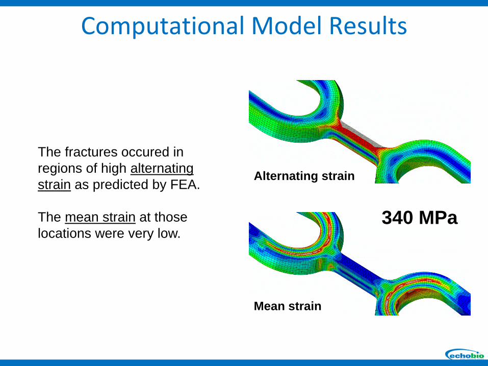
The fractures occured in regions of high alternating strain as predicted by FEA.
The mean strain at those locations were very low.
Alternating strain
Mean strain
340 MPa
Computational Model Results
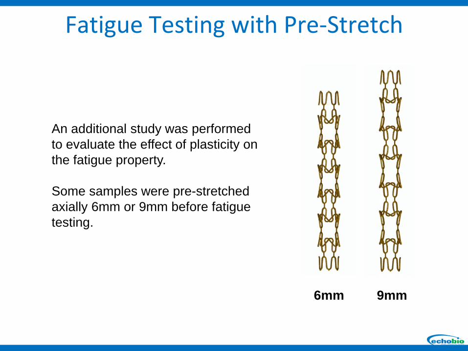
9mm6mm
An additional study was performed to evaluate the effect of plasticity on the fatigue property.
Some samples were pre-stretched axially 6mm or 9mm before fatigue testing.
Fatigue Testing with Pre-Stretch
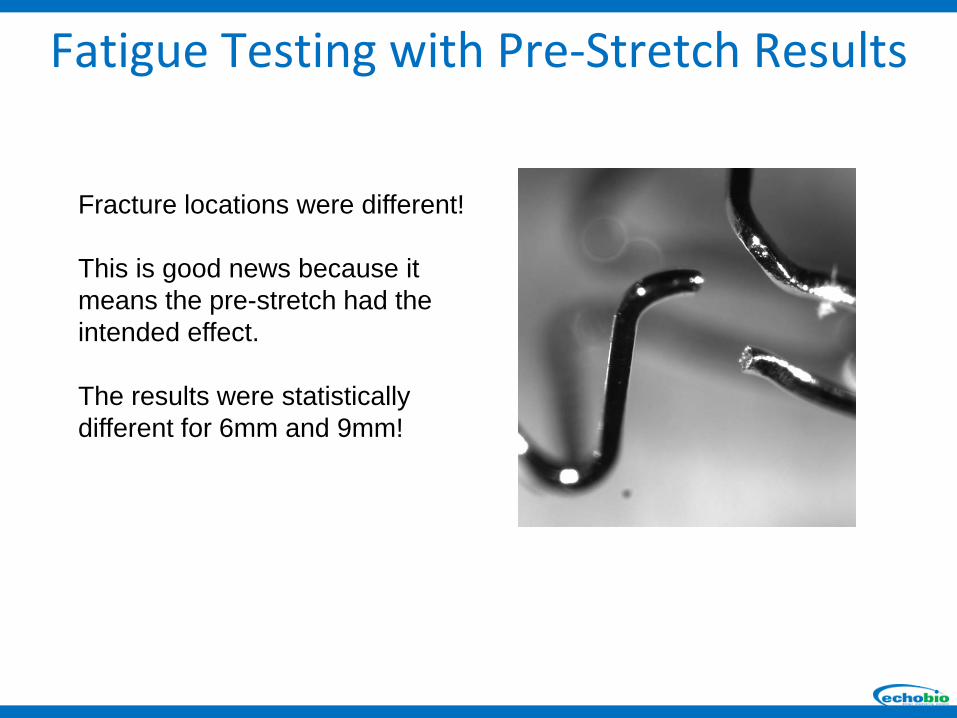
Fracture locations were different!
This is good news because it means the pre-stretch had the intended effect.
The results were statistically different for 6mm and 9mm!
Fatigue Testing with Pre-Stretch Results
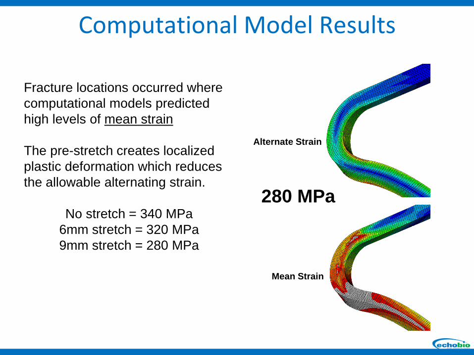
Fracture locations occurred where computational models predicted high levels of mean strain
The pre-stretch creates localized plastic deformation which reduces the allowable alternating strain.
No stretch = 340 MPa6mm stretch = 320 MPa9mm stretch = 280 MPa
Alternate Strain
Mean Strain
280 MPa
Computational Model Results
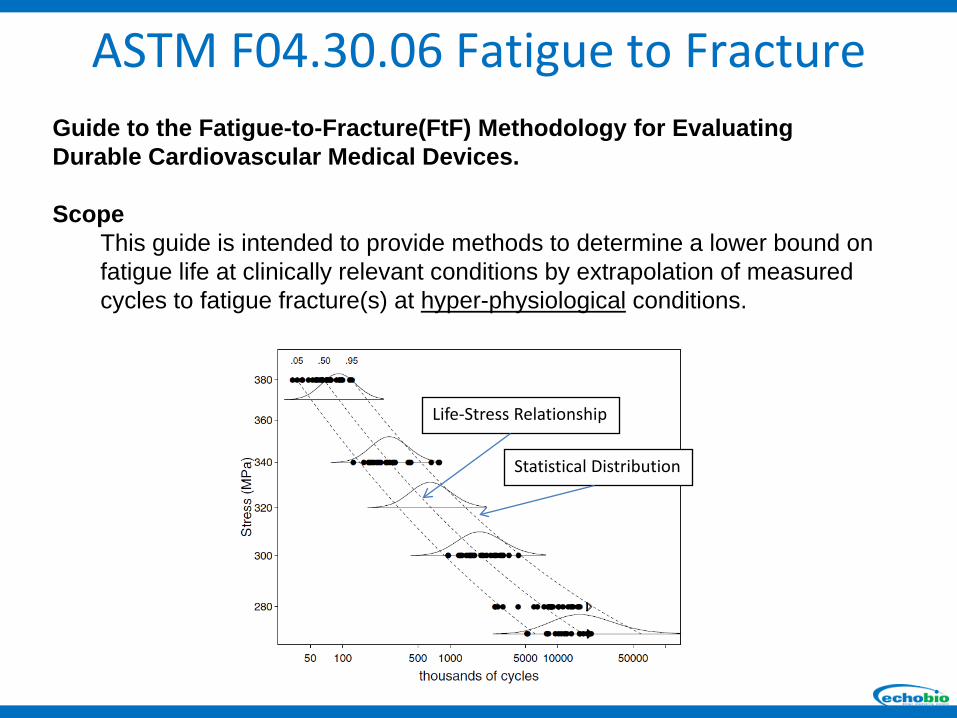
Statistical Distribution
Life-Stress Relationship
Guide to the Fatigue-to-Fracture(FtF) Methodology for Evaluating Durable Cardiovascular Medical Devices.
ScopeThis guide is intended to provide methods to determine a lower bound on fatigue life at clinically relevant conditions by extrapolation of measured cycles to fatigue fracture(s) at hyper-physiological conditions.
ASTM F04.30.06 Fatigue to Fracture
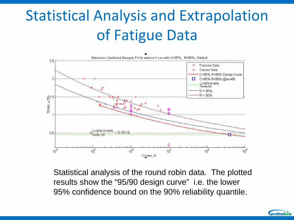
Statistical analysis of the round robin data. The plotted results show the “95/90 design curve” i.e. the lower 95% confidence bound on the 90% reliability quantile.
Statistical Analysis and Extrapolation of Fatigue Data
Computational models are most convincing when material input data includes probability
statistics and confidence intervals
Summary

ASTM F04.30.06Medical and Surgical Materials and Devices: Interventional Cardiology Task Group
Acknowledgements
Maureen Dreher
Andres SchulzRodney DwyerKasondra Totura