cardiosave intra-aortic balloon pump … of the cardiosave intra-aortic balloon pump. the cardiosave...
TRANSCRIPT

CARDIOSAVE™ INTRA-AORTIC BALLOON PUMP TRAINERUSER MANUAL

CARDIOSAVE™ Trainer | User Manual | 0070-00-0700
CopyrightAll rights reserved. No part of this publication may be duplicated,adapted or translated without prior written permission, exceptwithin the framework of the copyright laws.© Copyright 2011 Datascope Corp.™ Trademark of Datascope Trademark Corp.
ManufacturerDatascope Corp.1300 MacArthur Blvd.Mahwah, NJ 07430, USAPhone: 1 800 777 4222 or
1 201 995 8700Fax: 1 201 995 8910http://ca.maquet.comhttp://www.maquet.com

CARDIOSAVE™ Trainer | User Manual | 0070-00-0700
TABLE OF CONTENTS
Introduction | iDocument Conventions | iWarnings | iNotes | i
1 GETTING ACQUAINTED WITH THE CARDIOSAVE TRAINER
1.1 CARDIOSAVE Trainer General Description | 1 - 11.2 Product Controls and Functionality | 1 - 21.2.1 Pressure Key | 1 - 21.2.2 MODE Key | 1 - 31.2.3 Dysrhythmia Key | 1 - 41.2.4 Pacer Key | 1 - 51.2.5 Rate bpm Key | 1 - 61.2.6 NSR Key | 1 - 71.2.7 Vent Key | 1 - 81.2.8 Compressions Key | 1 - 91.2.9 ECG Lead Fault Key | 1 - 101.2.10 Noisy ECG Key | 1 - 111.3 Connectors and Cables | 1 - 121.4 Installation | 1 - 14
2 GENERAL USE AND STARTUP
2.1 Startup Steps for Using the Trainer | 2 - 1
3 USING THE CARDIOSAVE TRAINER
3.1 Conditions and Simulations on the CARDIOSAVE Trainer | 3 - 13.1.1 Zeroing (Conventional IAB) | 3 - 13.1.2 Suboptimal Diastolic Augmentation | 3 - 23.1.3 Arterial Pressure Waveform Artifact | 3 - 23.1.4 Loss of Arterial Pressure Waveform | 3 - 23.1.5 Cardiac Arrest | 3 - 23.1.6 Non-pulsatile Flow | 3 - 33.1.7 Atrial Fibrillation | 3 - 33.1.8 Ventricular Arrhythmias | 3 - 33.1.9 Various Pacer Settings | 3 - 33.1.10 Heart Rate Changes | 3 - 33.1.11 Normal Sinus Rhythm | 3 - 33.1.12 ECG Lead Fault | 3 - 43.1.13 ECG Artifact | 3 - 4
4 SPECIFICATIONS
4.1 IABP Trainer Specifications | 4 - 1
A APPENDIX
A.1 Warranty | A - iA.2 Datascope Corp.'s Responsibility | A - i

CARDIOSAVE™ Trainer | User Manual | 0070-00-0700
THIS PAGE INTENTIONALLY LEFT BLANK.

| CARDIOSAVE Trainer | Introduction | i |
CARDIOSAVE™ Trainer | User Manual | 0070-00-0700
INTRODUCTION
This manual provides instructions for the setup, usage, and training simulations with the CARDIOSAVE Trainer.
This section provides an introduction to the CARDIOSAVE Trainer. Chapter One of this manual covers the features, functionality and installation of the CARDIOSAVE Trainer. The second chapter covers the general use of the keypad, ECG and Pressure Signals, and specifications. The third chapter offers simulation procedures for training scenarios, and the final section covers the warranty for the Trainer.
DOCUMENT CONVENTIONS
Please read and adhere to all warnings, precautions and notes listed here and in the appropriate areas throughout this manual.
A WARNING is provided if there is reasonable evidence of an association of a serious hazard with the misuse of this device or when special attention is required for the safety of the patient.
A NOTE is provided in the appropriate areas throughout the manual when additional general information is applicable.
WARNINGS
NOTES
WARNING:
The CARDIOSAVE Trainer is intended only as a training device. It should never be connected to CARDIOSAVE when the pump is connected to a patient.
Note:In order to accurately evaluate alarm performance with the CARDIOSAVE Trainer, it is important to simulate real use conditions. Of particular importance is the backpressure seen by CARDIOSAVE during clinical use. This backpressure simulates patient blood pressure and its affects on the gas dynamics and thereby, the alarm detection process.

| Notes | CARDIOSAVE Trainer |
CARDIOSAVE™ Trainer | User Manual | 0070-00-0700
|iii
THIS PAGE INTENTIONALLY LEFT BLANK.

| CARDIOSAVE Trainer | Getting Acquainted with the CARDIOSAVE Trainer | 1 - 1 |
CARDIOSAVE™ Trainer | User Manual | 0070-00-0700
1 GETTING ACQUAINTED WITH THE CARDIOSAVE TRAINER
1.1 CARDIOSAVE TRAINER GENERAL DESCRIPTION
Figure 1-1: CARDIOSAVE Trainer
The CARDIOSAVE Trainer is not a medical device.
The CARDIOSAVE Trainer is used by health care clinicians and clinical representatives as an educational tool to simulate patient waveforms on CARDIOSAVE, which aids in the education and training of the CARDIOSAVE Intra-Aortic Balloon Pump.
The CARDIOSAVE Trainer is also used by the MAQUET sales team and clinical representatives during sales demonstrations to simulate patient waveforms on CARDIOSAVE for potential customers who are interested in purchasing the CARDIOSAVE Intra-Aortic Balloon Pump.
This Trainer supports only the CARDIOSAVE Intra-Aortic Balloon Pump. It does not and is not expected to support earlier generation MAQUET/Datascope IABPs.
CARDIOSAVETM TRAINER
VENT COMPRESSIONS
ASYSTOLE
NON-PULSEFLOW
60
80
100
130
NORMAL
SUBOPTIMAL
AP ARTIFACT
V
A-V
A
A-V DEMAND
RATEbpmPACERPRESSURE MODE
NOISYECG
PVC
COUPLETS
V-TACH
ATRIAL FIB
DYS RHYTHMIA
ECG LEADFAULT
NSR
Note:When a CARDIOSAVE Trainer is in use, CARDIOSAVE displays the Trainer in Use - NOT FOR CLINICAL USE! advisory message on the screen.
WARNING:
The CARDIOSAVE Trainer is intended only as a training device. It should never be connected to CARDIOSAVE when the pump is connected to a patient.

| Getting Acquainted with the CARDIOSAVE Trainer | CARDIOSAVE Trainer |
CARDIOSAVE™ Trainer | User Manual | 0070-00-0700
| 1 - 2
1.2 PRODUCT CONTROLS AND FUNCTIONALITY
1.2.1 PRESSURE KEY
The PRESSURE key controls various conditions that impact the appearance of the arterial pressure (AP) waveforms.
Figure 1-2: CARDIOSAVE Trainer Pressure Key Functions
Each time the PRESSURE key is pressed, it advances to the next pressure state in the group:
Normal Suboptimal AP Artifact
Underdamped Waveform Overdamped Waveform
Note:When a pressure state is active, the LED light next to it is illuminated or blinking.
Key Presses Pressure State Result
First Press Suboptimal Produces an augmented waveform that is
approximately 10 mmHg below the systolic peak
pressure, with a steady LED.
Second Press AP Artifact Produces an underdamped AP waveform with a
steady LED.
Third Press AP Artifact Produces an overdamped AP waveform and a
blinking LED.
Fourth Press Returns to Normal Pressure returns to normal state, which simulates an
optimal AP waveform.
| CARDIOSAVE Trainer | Getting Acquainted with the CARDIOSAVE Trainer | 1 - 3 |
CARDIOSAVE™ Trainer | User Manual | 0070-00-0700
1.2.2 MODE KEY
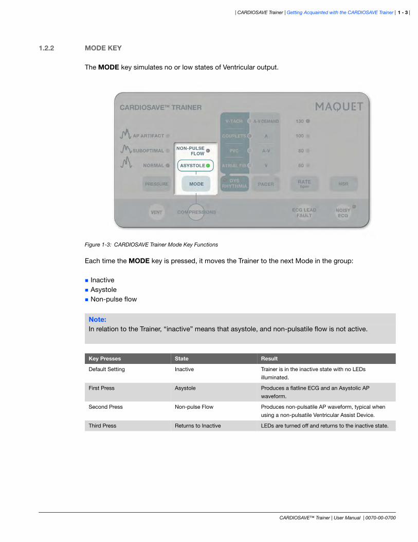
The MODE key simulates no or low states of Ventricular output.
Figure 1-3: CARDIOSAVE Trainer Mode Key Functions
Each time the MODE key is pressed, it moves the Trainer to the next Mode in the group:
Inactive Asystole Non-pulse flow
Note:In relation to the Trainer, “inactive” means that asystole, and non-pulsatile flow is not active.
Key Presses State Result
Default Setting Inactive Trainer is in the inactive state with no LEDs
illuminated.
First Press Asystole Produces a flatline ECG and an Asystolic AP
waveform.
Second Press Non-pulse Flow Produces non-pulsatile AP waveform, typical when
using a non-pulsatile Ventricular Assist Device.
Third Press Returns to Inactive LEDs are turned off and returns to the inactive state.

| Getting Acquainted with the CARDIOSAVE Trainer | CARDIOSAVE Trainer |
CARDIOSAVE™ Trainer | User Manual | 0070-00-0700
| 1 - 4
1.2.3 DYSRHYTHMIA KEY
The DYSRHYTHMIA key simulates various cardiac rhythms used to demonstrate the pump's behavior during common dysrhythmias.
Figure 1-4: CARDIOSAVE Trainer Dysrhythmia Key Functions
Each time the DYSRHYTHMIA key is pressed, it moves the Trainer to the next Dysrhythmia selection in the group (Atrial Fib, PVC, Couplets and V-Tach). The Dysrhythmia LED remains lit as well when the user cycles through each state of Dysrhythmia.
Note:When PVC, Couplets, or V-Tach is illuminated, the most recently selected heart rate is enabled.
Key Presses State Result
First Press Atrial Fib Dysrhythmia and the Atrial Fib LEDs are illuminated.
Turns off NSR LED, if lit.
Second Press PVC Dysrhythmia and the PVC LEDs are illuminated.
Third Press Couplets Dysrhythmia and the Couplets LEDs are illuminated.
Fourth Press V-Tach Dysrhythmia and the V-Tach LEDs are illuminated.
Fifth Press Deactivates Dysrhythmia state Dysrhythmia LEDs are turned off, and the NSR LED is
illuminated. The system goes into a normal sinus
rhythm.
Press NSR key Deactivates Dysrhythmia state Dysrhythmia LEDs are turned off, and the NSR LED is
illuminated. The system goes into a normal sinus
rhythm.
| CARDIOSAVE Trainer | Getting Acquainted with the CARDIOSAVE Trainer | 1 - 5 |
CARDIOSAVE™ Trainer | User Manual | 0070-00-0700
1.2.4 PACER KEY
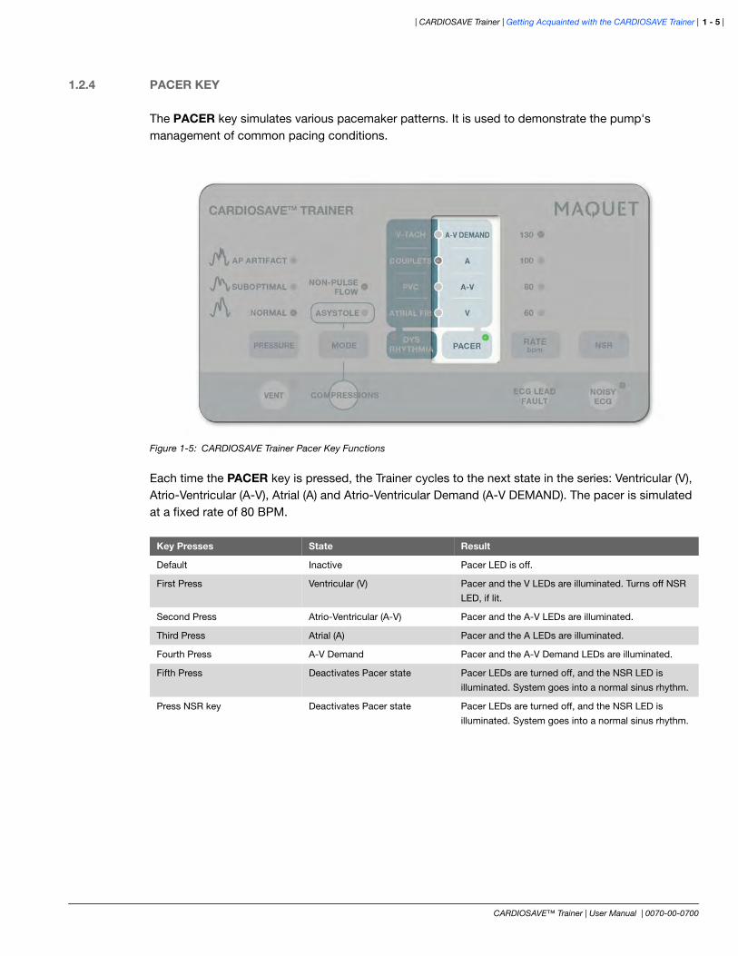
The PACER key simulates various pacemaker patterns. It is used to demonstrate the pump's management of common pacing conditions.
Figure 1-5: CARDIOSAVE Trainer Pacer Key Functions
Each time the PACER key is pressed, the Trainer cycles to the next state in the series: Ventricular (V), Atrio-Ventricular (A-V), Atrial (A) and Atrio-Ventricular Demand (A-V DEMAND). The pacer is simulated at a fixed rate of 80 BPM.
Key Presses State Result
Default Inactive Pacer LED is off.
First Press Ventricular (V) Pacer and the V LEDs are illuminated. Turns off NSR
LED, if lit.
Second Press Atrio-Ventricular (A-V) Pacer and the A-V LEDs are illuminated.
Third Press Atrial (A) Pacer and the A LEDs are illuminated.
Fourth Press A-V Demand Pacer and the A-V Demand LEDs are illuminated.
Fifth Press Deactivates Pacer state Pacer LEDs are turned off, and the NSR LED is
illuminated. System goes into a normal sinus rhythm.
Press NSR key Deactivates Pacer state Pacer LEDs are turned off, and the NSR LED is
illuminated. System goes into a normal sinus rhythm.
| Getting Acquainted with the CARDIOSAVE Trainer | CARDIOSAVE Trainer |
CARDIOSAVE™ Trainer | User Manual | 0070-00-0700
| 1 - 6
1.2.5 RATE BPM KEY
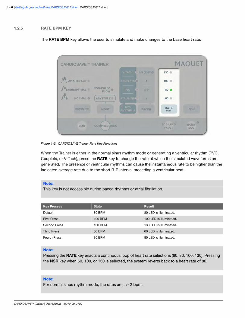
The RATE BPM key allows the user to simulate and make changes to the base heart rate.
Figure 1-6: CARDIOSAVE Trainer Rate Key Functions
When the Trainer is either in the normal sinus rhythm mode or generating a ventricular rhythm (PVC, Couplets, or V-Tach), press the RATE key to change the rate at which the simulated waveforms are generated. The presence of ventricular rhythms can cause the instantaneous rate to be higher than the indicated average rate due to the short R-R interval preceding a ventricular beat.
Note:This key is not accessible during paced rhythms or atrial fibrillation.
Key Presses State Result
Default 80 BPM 80 LED is illuminated.
First Press 100 BPM 100 LED is illuminated.
Second Press 130 BPM 130 LED is illuminated.
Third Press 60 BPM 60 LED is illuminated.
Fourth Press 80 BPM 80 LED is illuminated.
Note:Pressing the RATE key enacts a continuous loop of heart rate selections (60, 80, 100, 130). Pressing the NSR key when 60, 100, or 130 is selected, the system reverts back to a heart rate of 80.
Note:For normal sinus rhythm mode, the rates are +/- 2 bpm.

| CARDIOSAVE Trainer | Getting Acquainted with the CARDIOSAVE Trainer | 1 - 7 |
CARDIOSAVE™ Trainer | User Manual | 0070-00-0700
1.2.6 NSR KEY
The NSR key conveniently returns the system back to a normal sinus rhythm from other Trainer modes.
Figure 1-7: CARDIOSAVE Trainer NSR Key
Each time the NSR key is pressed (if not already illuminated), the Trainer returns to a normal sinus rhythm with a heart rate of 80.
Key Presses State Result
Any Press Returns to normal sinus rhythm
(if NSR key is not already
illuminated).
NSR LED is illuminated. Any asystole, dysrhythmia,
and pacer modes are terminated.
Any Press Resets RATE NSR LED is illuminated, or remains illuminated.
Resets RATE to 80 BPM.

| Getting Acquainted with the CARDIOSAVE Trainer | CARDIOSAVE Trainer |
CARDIOSAVE™ Trainer | User Manual | 0070-00-0700
| 1 - 8
1.2.7 VENT KEY
The VENT key simulates the arterial pressure transducer being vented to atmospheric pressure.
Figure 1-8: CARDIOSAVE Trainer Vent Key
Each time the VENT key is pressed, the Trainer simulates a flat lined 0(+/-10) mmHg output.
Key Presses State Result
Default Setting Inactive VENT LED is not illuminated. AP waveform is output
as normal.
First Press Active VENT LED is illuminated. Overrides the output of the
AP waveform and simulates a flatlined 0(+/-10) mmHg
output.
Second Press Returns to inactive VENT LED is turned off and returns to the default
state of a normal AP waveform output.
| CARDIOSAVE Trainer | Getting Acquainted with the CARDIOSAVE Trainer | 1 - 9 |
CARDIOSAVE™ Trainer | User Manual | 0070-00-0700
1.2.8 COMPRESSIONS KEY
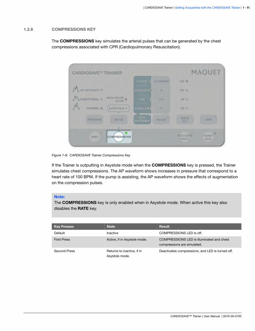
The COMPRESSIONS key simulates the arterial pulses that can be generated by the chest compressions associated with CPR (Cardiopulmonary Resuscitation).
Figure 1-9: CARDIOSAVE Trainer Compressions Key
If the Trainer is outputting in Asystole mode when the COMPRESSIONS key is pressed, the Trainer simulates chest compressions. The AP waveform shows increases in pressure that correspond to a heart rate of 100 BPM. If the pump is assisting, the AP waveform shows the effects of augmentation on the compression pulses.
Note:The COMPRESSIONS key is only enabled when in Asystole mode. When active this key also disables the RATE key.
Key Presses State Result
Default Inactive COMPRESSIONS LED is off.
First Press Active, if in Asystole mode. COMPRESSIONS LED is illuminated and chest
compressions are simulated.
Second Press Returns to inactive, if in
Asystole mode.
Deactivates compressions, and LED is turned off.

| Getting Acquainted with the CARDIOSAVE Trainer | CARDIOSAVE Trainer |
CARDIOSAVE™ Trainer | User Manual | 0070-00-0700
| 1 - 10
1.2.9 ECG LEAD FAULT KEY
The ECG LEAD FAULT key simulates the disconnection of multiple ECG skin electrodes.
Figure 1-10: CARDIOSAVE Trainer ECG LEAD FAULT Key
Each time the ECG LEAD FAULT key is pressed, the Trainer simulates an ECG signal that has faulted,
resulting in a flatlined ECG.
Key Presses State Result
Default Setting Inactive ECG Lead Fault is not illuminated.
First Press Active ECG Lead Fault is illuminated.
Simulates an ECG signal that is
faulted and flatlined.
Second Press Returns to inactive LED is turned off and ECG signal is
restored.
| CARDIOSAVE Trainer | Getting Acquainted with the CARDIOSAVE Trainer | 1 - 11 |
CARDIOSAVE™ Trainer | User Manual | 0070-00-0700
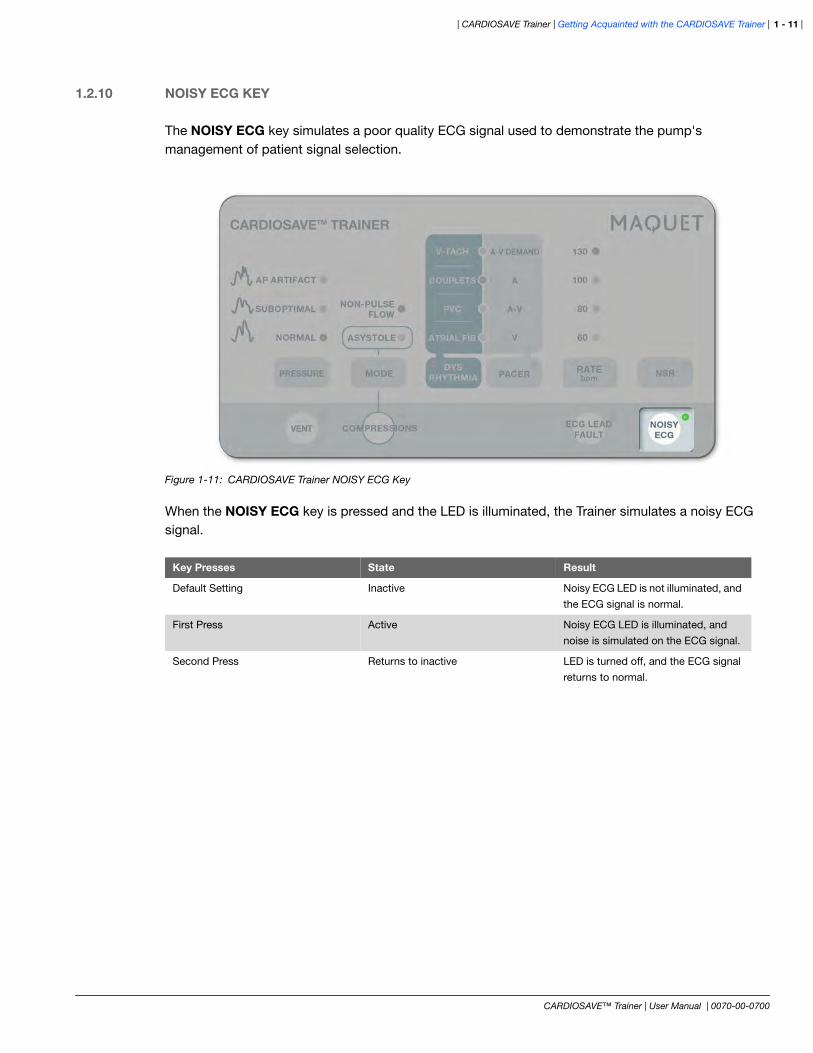
1.2.10 NOISY ECG KEY
The NOISY ECG key simulates a poor quality ECG signal used to demonstrate the pump's management of patient signal selection.
Figure 1-11: CARDIOSAVE Trainer NOISY ECG Key
When the NOISY ECG key is pressed and the LED is illuminated, the Trainer simulates a noisy ECG signal.
Key Presses State Result
Default Setting Inactive Noisy ECG LED is not illuminated, and
the ECG signal is normal.
First Press Active Noisy ECG LED is illuminated, and
noise is simulated on the ECG signal.
Second Press Returns to inactive LED is turned off, and the ECG signal
returns to normal.

| Getting Acquainted with the CARDIOSAVE Trainer | CARDIOSAVE Trainer |
CARDIOSAVE™ Trainer | User Manual | 0070-00-0700
| 1 - 12
1.3 CONNECTORS AND CABLES
The Trainer plugs into the Direct ECG and Pressure Inputs on the back panel of CARDIOSAVE. The Trainer Connector plugs into the Trainer Input, also on the back of the pump. CARDIOSAVE must be powered on in order for the Trainer to function.
Figure 1-12: CARDIOSAVE IABP with the Trainer mounted and connected
CARDIOSAVETM TRAINER
VENT COMPRESSIONS
ASYSTOLE
NON-PULSEFLOW
60
80
100
130
NORMAL
SUBOPTIMAL
AP ARTIFACT
V
A-V
A
A-V DEMAND
RATEbpm
PACERPRESSURE MODE
NOISYECG
PVC
COUPLETS
V-TACH
ATRIAL FIB
DYS RHYTHMIA
ECG LEADFAULT
NSR
WARNING:
The CARDIOSAVE Trainer is intended only as a training device. It should never be connected to CARDIOSAVE when the pump is connected to a patient.
| CARDIOSAVE Trainer | Getting Acquainted with the CARDIOSAVE Trainer | 1 - 13 |
CARDIOSAVE™ Trainer | User Manual | 0070-00-0700
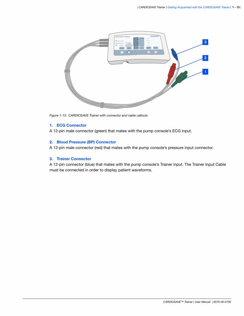
Figure 1-13: CARDIOSAVE Trainer with connector and cable callouts
1. ECG ConnectorA 12-pin male connector (green) that mates with the pump console’s ECG input.
2. Blood Pressure (BP) ConnectorA 12-pin male connector (red) that mates with the pump console’s pressure input connector.
3. Trainer ConnectorA 12-pin connector (blue) that mates with the pump console’s Trainer input. The Trainer Input Cable must be connected in order to display patient waveforms.
CARDIOSAVETM TRAINER
VENT COMPRESSIONS
ASYSTOLE
NON-PULSEFLOW
60
80
100
130
NORMAL
SUBOPTIMAL
AP ARTIFACT
V
A-V
A
A-V DEMAND
RATEbpmPACERPRESSURE MODE
NOISYECG
PVC
COUPLETS
V-TACH
ATRIAL FIB
DYS RHYTHMIA
ECG LEADFAULT
NSR
2
1
3

| Getting Acquainted with the CARDIOSAVE Trainer | CARDIOSAVE Trainer |
CARDIOSAVE™ Trainer | User Manual | 0070-00-0700
| 1 - 14
1.4 INSTALLATION
The CARDIOSAVE Trainer plugs directly into the ECG, Pressure and Trainer inputs on the back pannel of the CARDIOSAVE IABP.
The GREEN ECG connector from the Trainer plugs into location 1. The RED BP connector from the Trainer plugs into location 2. The BLUE Trainer Connector from the Trainer plugs into location 3.
Figure 1-14: CARDIOSAVE IABP Back Panel
1
2
3
Note:The CARDIOSAVE IABP console must be turned on in order to use the Trainer.

| CARDIOSAVE Trainer | General Use and Startup | 2 - 1 |
CARDIOSAVE™ Trainer | User Manual | 0070-00-0700
2 GENERAL USE AND STARTUP
2.1 STARTUP STEPS FOR USING THE TRAINER
1. Turn on CARDIOSAVE.
2. Attach the CARDIOSAVE Trainer as described in “Installation” on page 1-14. The message Trainer in Use - NOT FOR CLINICAL USE! is displayed on the Monitor Display.
3. Attach an IAB with a helium extender tubing to the system. If attaching a MAQUET/Datascope Fiber-Optic IAB, the sensor connector should also be connected.
4. If using a conventional IAB, press the VENT key to simulate venting a transducer to atmosphere. Zero the IABP by pressing and holding the Zero Pressure key on the Touchscreen for 2 seconds. Once zeroed, the message Zeroing Complete appears above the arterial pressure waveform on the Monitor Display and zeros are displayed to the right of the arterial pressure waveform.
5. Press the START key. The IAB initiates an Autofill (and calibration if a MAQUET/Datascope Fiber-Optic IAB is being used). Once complete, pumping begins at MAX augmentation.
Note:The default Operation Mode is AUTO and the frequency is 1:1.
Note:If using a MAQUET/Datascope Fiber-Optic IAB, there is no need to zero. Once the Start key is pressed, the IABP automatically performs a calibration.

| General Use and Startup | CARDIOSAVE Trainer |
CARDIOSAVE™ Trainer | User Manual | 0070-00-0700
| 2 - 2
THIS PAGE INTENTIONALLY LEFT BLANK.

| CARDIOSAVE Trainer | Using the CARDIOSAVE Trainer | 3 - 1 |
CARDIOSAVE™ Trainer | User Manual | 0070-00-0700
3 USING THE CARDIOSAVE TRAINER
3.1 CONDITIONS AND SIMULATIONS ON THE CARDIOSAVE TRAINER
This chapter covers some of the possible simulations and conditions that can be generated with the CARDIOSAVE Trainer. Not all simulations and alarms are listed.
Figure 3-1: CARDIOSAVE Trainer Keypad
3.1.1 ZEROING (CONVENTIONAL IAB)
1. Press the VENT key on the Trainer keypad, then press Zero Pressure key on Touchscreen for 2 seconds. Once zeroed, the message Zeroing Complete appears above the arterial pressure waveform on the Monitor Display and zeros will be displayed to the right of the arterial pressure waveform.
2. Press the VENT key again and the arterial pressure indices are now displayed on the Monitor Display.
WARNING:
The CARDIOSAVE Trainer is intended only as a training device. It should never be connected to CARDIOSAVE when the pump is connected to a patient.
CARDIOSAVETM TRAINER
ASYSTOLE
NON-PULSEFLOW
60
80
100
130
NORMAL
SUBOPTIMAL
AP ARTIFACT
V
A-V
A
A-V DEMAND
RATEbpmPACERPRESSURE MODE
PVC
COUPLETS
V-TACH
ATRIAL FIB
DYS RHYTHMIA NSR
VENT COMPRESSIONS NOISYECG
ECG LEADFAULT
Note:If a MAQUET/Datascope Fiber-Optic IAB pump is connected, zeroing is not necessary because the IABP will automatically perform a calibration on startup when the Start key is pressed. To manually initiate a calibration, press the Calibrate Pressure key for two seconds, while pumping.

| Using the CARDIOSAVE Trainer | CARDIOSAVE Trainer |
CARDIOSAVE™ Trainer | User Manual | 0070-00-0700
| 3 - 2
3.1.2 SUBOPTIMAL DIASTOLIC AUGMENTATION
1. Press the PRESSURE key until the SUBOPTIMAL LED is illuminated. This typically triggers the Augmentation Below Limit Set alarm.
2. To return to super-systolic diastolic augmentation, press the PRESSURE key until the NORMAL LED is illuminated.
3.1.3 ARTERIAL PRESSURE WAVEFORM ARTIFACT
1. Press the PRESSURE key until the AP ARTIFACT LED is illuminated with a solid LED. This simulates an underdamped arterial pressure waveform.
2. Press the PRESSURE key again and the LED will blink next to AP ARTIFACT. This simulates an overdamped arterial pressure waveform.
3. To restore a crisp, clean arterial pressure waveform, press the PRESSURE key until the NORMAL LED is illuminated.
3.1.4 LOSS OF ARTERIAL PRESSURE WAVEFORM
1. For a conventional IAB, disconnect the Trainer pressure cable from CARDIOSAVE. After reconnecting, zeroing is necessary.
2. For a MAQUET/Datascope Fiber-Optic IAB, disconnect the Trainer pressure cable and the Fiber-Optic Sensor from the rear panel of CARDIOSAVE. Once both are reconnected, a calibration automatically occurs after 20 seconds, or a manual calibration can be invoked rather than waiting.
3.1.5 CARDIAC ARREST
1. Press the MODE key until the ASYSTOLE LED is illuminated. This creates a flatlined ECG and arterial pressure waveform. The No Trigger alarm sounds.
2. To simulate chest compressions while in ASYSTOLE mode, press the COMPRESSIONS key. Pumping automatically resumes in Pressure trigger (if in Auto Operation Mode) at a heart rate of 100 BPM.
3. To return to a normal sinus rhythm (NSR) and blood pressure, press the NSR key.
Note:This simulation causes the No Pressure Source Available alarm to sound.
| CARDIOSAVE Trainer | Using the CARDIOSAVE Trainer | 3 - 3 |
CARDIOSAVE™ Trainer | User Manual | 0070-00-0700
3.1.6 NON-PULSATILE FLOW
1. Press the MODE key until the NON-PULSE FLOW LED is illuminated. While the pump is in Standby mode, this simulates a low pulsatility arterial pressure waveform. While CARDIOSAVE is assisting, this simulates an example of how the arterial pressure waveform may appear with counterpulsation therapy.
2. To resume a normal arterial pressure waveform, press the MODE key once.
3.1.7 ATRIAL FIBRILLATION
1. Press the DYSRHYTHMIA key until the ATRIAL FIB LED is illuminated. After a short time period, the pump enacts Auto R-Wave Deflate.
2. To return to a normal sinus rhythm, press the NSR key. After a short time period, the Auto R-Wave Deflate will be inactivated.
3.1.8 VENTRICULAR ARRHYTHMIAS
1. To simulate PVCs, Couplets and runs of Ventricular Tachycardia, press the DYSRHYTHMIA key until the desired arrhythmia LED is illuminated.
2. To return to a normal sinus rhythm, press the NSR key.
3.1.9 VARIOUS PACER SETTINGS
1. To simulate A (Atrial), V (Ventricular), and A-V (Atrio-Ventricular) paced rhythms, press the PACER key until the desired paced rhythm LED is illuminated.
2. To return to a normal sinus rhythm, press the NSR key.
3.1.10 HEART RATE CHANGES
To simulate heart rates of 60, 80, 100, and 130, press the RATE key until the desired heart rate LED is illuminated.
3.1.11 NORMAL SINUS RHYTHM
Whenever a normal sinus rhythm is desired, press the NSR key.
| Using the CARDIOSAVE Trainer | CARDIOSAVE Trainer |
CARDIOSAVE™ Trainer | User Manual | 0070-00-0700
| 3 - 4
3.1.12 ECG LEAD FAULT
1. While in Auto Operation Mode, press the ECG LEAD FAULT key and a green LED illuminates. A flatlined ECG appears and the pump switches to Pressure trigger.
2. Press the ECG LEAD FAULT key a second time and a ECG waveform reappears and the pump switches back to ECG trigger after a short time period.
3.1.13 ECG ARTIFACT
1. While in Auto Operation Mode, press the NOISY ECG key. The pump cycles through all available leads, then switches to Pressure trigger.
2. Press the NOISY ECG key a second time and the artifact disappears. The pump switches back to ECG trigger after an appropriate amount of time, resulting in a clean signal.

| CARDIOSAVE Trainer | Specifications | 4 - 1 |
CARDIOSAVE™ Trainer | User Manual | 0070-00-0700
4 SPECIFICATIONS
4.1 IABP TRAINER SPECIFICATIONS
Feature Specification
Heart Rate 60, 80, 100, 130, (±2%)
QRS Complex
Amplitude 0.7 mV in lead II, (±0.05) mV peak to peak between 75
V and 100 V in AVL
Duration 92 (±10%) msec
Impedance: between C and RL <100
Arterial Pressure
Sensitivity 25 V/mmHg nominal
Amplitude 101/52 (±3) mmHg, @ 80 BPM
Impedance <100
Delay 40 (±10%) msec
Pacers
Atrial 172 (±16) msec, prior to the “Q” wave
Ventricular 40 (±4) msec prior to the “Q” wave
A-V 172 (±16) msec and 40 (±4) msec respectively, prior
to the “Q” wave
Normal Amplitude > 3 mV in Lead II
Normal Duration 0.9 - 2.0 msec
Unenhanced Amplitude 0.90 (±0.10) mV
Unenhanced Duration 16 (±4) msec measured from start of pulse to 50%
point on decaying waveform
Tail No Tails
Power Consumption 100 mA maximum @ 5V nominal
Mechanical
Size 7.6"(L) x 4.5" (W) x 2.0" (H)
Weight 16 oz

| Specifications | CARDIOSAVE Trainer |
CARDIOSAVE™ Trainer | User Manual | 0070-00-0700
| 4 - 2
THIS PAGE INTENTIONALLY LEFT BLANK.

| CARDIOSAVE Trainer | Appendix | A - i |
CARDIOSAVE™ Trainer | User Manual | 0070-00-0700
A APPENDIX
A.1 WARRANTY
Datascope Corp. warrants that its products will be free from defects in workmanship and materials for a period of one year from the date of purchase except that disposable or one-use products are warranted to be free from defects in workmanship and materials up to a date one year from the date of purchase or the date of first use, whichever is sooner.
Datascope Corp. shall not be liable for any incidental, special or consequential loss, damage or expense directly or indirectly arising from the use of its products. Liability under this warranty and the buyer’s exclusive remedy under this warranty, is limited to servicing or replacing, at Datascope Corp’s option, at the factory or at an authorized Datascope Distributor, any product which shall, under normal use, appear to Datascope Corp. to have been defective in material or workmanship.
No agent, employee, or representative of Datascope Corp. has any authority to bind Datascope Corp. to any affirmation, representation, or warranty concerning its products, and any affirmation, representation or warranty made by any agent, employee, or representative shall not be enforceable by buyer.
This warranty is expressly in lieu of any other expressed or implied warranties, including any implied warranty of merchantability or fitness, and of any other obligation on the part of the seller.
Damage to any product or parts through misuse, neglect, accident or by affixing any nonstandard accessory attachments, or by any customer modification, voids this warranty. Datascope Corp. makes no warranty whatever in regard to trade accessories, such being subject to the warranty of their respective manufacturers.
A condition of this warranty is that this equipment or any accessories which are claimed to be defective be returned when authorized by Datascope, freight prepaid to Datascope Corp., Mahwah, New Jersey. Datascope Corp. shall not have any responsibility in the event of loss or damage in transit.
A.2 DATASCOPE CORP.'S RESPONSIBILITY
Datascope Corp. is responsible for the effects on safety, reliability and performance of the equipment only if:
1. Assembly operations, extensions, readjustments, modifications or repairs are carried out by persons authorized by MAQUET; and
2. The electrical installation of the relevant room complies with IEC requirements (VDE 0107); and
3. The equipment is used in accordance with the Instructions for Use.
To reorder the IABP Trainer User Manual, use part number 0070-00-0700.

GETINGE GROUP is a leading global provider of products andsystems that contribute to quality enhancement and cost efficiencywithin healthcare and life sciences. We operate under the three brandsof ArjoHuntleigh, GETINGE and MAQUET. ArjoHuntleigh focuses onpatient mobility and wound management solutions. GETINGE provi-des solutions for infection control and prevention within healthcareand life sciences. MAQUET specializes in solutions, therapies andproducts for surgical interventions and intensive care.
Datascope Corp.1300 MacArthur Blvd.Mahwah, NJ 07430, USAPhone: 1 800 777 4222 or
1 201 995 8700Fax: 1 201 995 8910http://ca.maquet.comhttp://www.maquet.com
MA
QU
ET
is a
Tra
dem
ark
of M
AQ
UE
T G
mb
H &
Co.
KG
. Cop
yrig
ht 2
011
Dat
asco
pe
Cor
p. o
r its
aff
iliat
es. A
ll rig
hts
rese
rved
. 11/
11.
P/N
: 007
0-00
-070
0 R
evA