cardinal health™ negative pressure wound …...simple operation: negative pressure wound therapy...
TRANSCRIPT

1
Cardinal Health™ Negative Pressure Wound Therapy CATALYST™
Clinician User Manual

Clin
icia
n U
ser
Man
ual
2
CAUTION: This Cardinal Health™ CATALYST™ NPWT Clinician User Manual is not a guarantee or warranty. It is intended only as an operational guide. For additional information and questions, please contact Cardinal Health Customer Service at 1.866.484.6798. In order for the Cardinal Health™ CATALYST™ to provide safe, reliable, and proper performance, the following conditions must be met. Failure to comply with these conditions voids all pertinent warranties.
• There are no user serviceable components in the CATALYST™. All assembly, modification, maintenance and/or repair of the CATALYST™ other than basic cleaning must be carried out only by qualified personnel authorized by Cardinal Health.
• The electrical installation of the room in which CATALYST™ is used complies with the appropriate electrical standards.
• The CATALYST™ must be used in accordance with this Clinician User Manual and all associated labeling.
• Any CATALYST™ that does not function as expected must be returned to Cardinal Health.
CAUTION: Federal law restricts this device to sale by, or on the order of, a physician. As with any prescription medical device, failure to follow product instructions or changing settings and performing therapy applications without the express direction and/or supervision of a trained clinical caregiver may lead to improper product performance and the potential for serious or fatal injury.
Clin
icia
n U
ser
Man
ual
3
Safety and WarningsNote to healthcare personnel providing training to lay users or lay caregivers (lay responsible organizations): Be sure to include all of the warnings below when providing training to lay operators, especially in a home care environment. Lay users and caregivers should contact Customer Support if there is a change in the performance of the CATALYST™. Additionally, lay users and caregivers should be instructed on proper cleaning procedures to avoid hazards such as electric shock. Lay users and caregivers should also be trained on inappropriate environments for use (e.g. bathtub). For guidance on training, please contact Customer Support.
WARNING: Strangulation hazard. Do not leave A.C. Power Adapter cord, tubing or other choking hazards where infants or young children can become caught. If these objects get wrapped around the neck, strangulation and death can occur.
WARNING: The CATALYST™ contains small parts, which could become detached and pose a choking hazard. Some of these components could be inhaled or swallowed by a small child, toddler or infant, which could result in suffocation or death. Keep all parts of the CATALYST™ out of reach of small children.
WARNING: Do not modify this equipment without authorization from the manufacturer. Modification of this system could result in physical hazards, including delayed therapy, electrocution and fire. These hazards could result in injury or death.
WARNING: Use only the Cardinal Health™ NPWT Occlusion Detection Dressing and accessories listed in this manual. Use of other dressings and accessories can create hazardous situations, including improper therapy or delayed therapy. This could result in improper healing, damage to the wound area and infection.
CAUTION: Use the CATALYST™ only as described in this user manual. Do not interconnect the CATALYST™ with other devices not included in this user manual. Failure to comply could result in improper therapy and could result in damage to the CATALYST™.
CAUTION: This system is not intended to be used in MRI environments or in the presence of strong magnetic fields. Do not use the CATALYST™ in any areas with strong magnetic fields. The system contains metal components which could cause unintended movement. This unintended movement could cause clinician or patient harm due to falling objects or collisions.
CAUTION: If you are in an environment with pet hair, please use caution when adhering the wound dressing to the wound site. Pet hair could contaminate the wound site and prevent adhesion of the wound dressing. This could result in possible infection of the wound or reduced effectiveness of the system.
CAUTION: The CATALYST™ system can be used outdoors for short periods of time (not more than 24 hours). Shelter from the rain.
Clin
icia
n U
ser
Man
ual
4
Table of Contents
1. Introduction . . . . . . . . . . . . . . . . . . . . . . . . . . . . . . . . . . . . . . . . . . . . . . . . . . . . . . . . . . . . . . . . . . . . . . . . . . . .5 1.1 Indications for Use . . . . . . . . . . . . . . . . . . . . . . . . . . . . . . . . . . . . . . . . . . . . . . . . . . . . . . . . . . . . . . . . . . . . . . . . . . . . 5 1.2 Contraindications. . . . . . . . . . . . . . . . . . . . . . . . . . . . . . . . . . . . . . . . . . . . . . . . . . . . . . . . . . . . . . . . . . . . . . . . . . . . . 6 1.3 Precautions . . . . . . . . . . . . . . . . . . . . . . . . . . . . . . . . . . . . . . . . . . . . . . . . . . . . . . . . . . . . . . . . . . . . . . . . . . . . . . . . . . 6 1.4 Safety Tips . . . . . . . . . . . . . . . . . . . . . . . . . . . . . . . . . . . . . . . . . . . . . . . . . . . . . . . . . . . . . . . . . . . . . . . . . . . . . . . . . . 7 1.5 Features . . . . . . . . . . . . . . . . . . . . . . . . . . . . . . . . . . . . . . . . . . . . . . . . . . . . . . . . . . . . . . . . . . . . . . . . . . . . . . . . . . . . 8
2. Care & Cleaning . . . . . . . . . . . . . . . . . . . . . . . . . . . . . . . . . . . . . . . . . . . . . . . . . . . . . . . . . . . . . . . . . . . . . . . . 10 2.1 Cleaning the CATALYST™ . . . . . . . . . . . . . . . . . . . . . . . . . . . . . . . . . . . . . . . . . . . . . . . . . . . . . . . . . . . . . . . . . . . . . . 10 2.2 A.C. Power Adapter Inspection . . . . . . . . . . . . . . . . . . . . . . . . . . . . . . . . . . . . . . . . . . . . . . . . . . . . . . . . . . . . . . . . . 11
3. Patient Care . . . . . . . . . . . . . . . . . . . . . . . . . . . . . . . . . . . . . . . . . . . . . . . . . . . . . . . . . . . . . . . . . . . . . . . . . . 12 3.1 Applying the NPWT Occlusion Detection Dressing . . . . . . . . . . . . . . . . . . . . . . . . . . . . . . . . . . . . . . . . . . . . . . . . 12 3.2 Inserting the NPWT Canister . . . . . . . . . . . . . . . . . . . . . . . . . . . . . . . . . . . . . . . . . . . . . . . . . . . . . . . . . . . . . . . . . . 15 3.3 Removing the NPWT Canister . . . . . . . . . . . . . . . . . . . . . . . . . . . . . . . . . . . . . . . . . . . . . . . . . . . . . . . . . . . . . . . . . 16 3.4 Delivering Simultaneous Irrigation™ Technology . . . . . . . . . . . . . . . . . . . . . . . . . . . . . . . . . . . . . . . . . . . . . . . . . 17 3.5 NPWT Occlusion Detection Y Connector . . . . . . . . . . . . . . . . . . . . . . . . . . . . . . . . . . . . . . . . . . . . . . . . . . . . . . . . . 20 3.6 Removing the NPWT Occlusion Detection Dressing . . . . . . . . . . . . . . . . . . . . . . . . . . . . . . . . . . . . . . . . . . . . . . . 21 3.7 Disposal of Used Components . . . . . . . . . . . . . . . . . . . . . . . . . . . . . . . . . . . . . . . . . . . . . . . . . . . . . . . . . . . . . . . . . 22
4. Operating Instructions . . . . . . . . . . . . . . . . . . . . . . . . . . . . . . . . . . . . . . . . . . . . . . . . . . . . . . . . . . . . . . . . . 23 4.1 On/Off . . . . . . . . . . . . . . . . . . . . . . . . . . . . . . . . . . . . . . . . . . . . . . . . . . . . . . . . . . . . . . . . . . . . . . . . . . . . . . . . . . . . . 23 4.2 Power-Up Procedure . . . . . . . . . . . . . . . . . . . . . . . . . . . . . . . . . . . . . . . . . . . . . . . . . . . . . . . . . . . . . . . . . . . . . . . . . 24 4.3 Negative Pressure Wound Therapy Setting Adjustment . . . . . . . . . . . . . . . . . . . . . . . . . . . . . . . . . . . . . . . . . . . . 24 4.4 Negative Pressure Wound Therapy Selection Lock/Unlock . . . . . . . . . . . . . . . . . . . . . . . . . . . . . . . . . . . . . . . . . . 25 4.5 Intermittent Mode On/Off . . . . . . . . . . . . . . . . . . . . . . . . . . . . . . . . . . . . . . . . . . . . . . . . . . . . . . . . . . . . . . . . . . . . 25 4.6 Therapy Timer Display . . . . . . . . . . . . . . . . . . . . . . . . . . . . . . . . . . . . . . . . . . . . . . . . . . . . . . . . . . . . . . . . . . . . . . . . 25 4.7 Alert Volume . . . . . . . . . . . . . . . . . . . . . . . . . . . . . . . . . . . . . . . . . . . . . . . . . . . . . . . . . . . . . . . . . . . . . . . . . . . . . . . 26 4.8 Battery Operation . . . . . . . . . . . . . . . . . . . . . . . . . . . . . . . . . . . . . . . . . . . . . . . . . . . . . . . . . . . . . . . . . . . . . . . . . . . 26 4.9 Troubleshooting . . . . . . . . . . . . . . . . . . . . . . . . . . . . . . . . . . . . . . . . . . . . . . . . . . . . . . . . . . . . . . . . . . . . . . . . . . . . 28
5. Symbols Glossary . . . . . . . . . . . . . . . . . . . . . . . . . . . . . . . . . . . . . . . . . . . . . . . . . . . . . . . . . . . . . . . . . . . . . . 30
6. Specifications . . . . . . . . . . . . . . . . . . . . . . . . . . . . . . . . . . . . . . . . . . . . . . . . . . . . . . . . . . . . . . . . . . . . . . . . . 39 6.1 Electromagnetic Compatibility . . . . . . . . . . . . . . . . . . . . . . . . . . . . . . . . . . . . . . . . . . . . . . . . . . . . . . . . . . . . . . . . 40
7. Additional Parts . . . . . . . . . . . . . . . . . . . . . . . . . . . . . . . . . . . . . . . . . . . . . . . . . . . . . . . . . . . . . . . . . . . . . . . 42 7.1 Replacement Product . . . . . . . . . . . . . . . . . . . . . . . . . . . . . . . . . . . . . . . . . . . . . . . . . . . . . . . . . . . . . . . . . . . . . . . . 42 7.2 Disposables and Accessories . . . . . . . . . . . . . . . . . . . . . . . . . . . . . . . . . . . . . . . . . . . . . . . . . . . . . . . . . . . . . . . . . . . 42
8. Questions & Information . . . . . . . . . . . . . . . . . . . . . . . . . . . . . . . . . . . . . . . . . . . . . . . . . . . . . . . . . . . . . . . . 43

5
1. In
tro
du
ctio
n
1. Introduction The Cardinal Health™ CATALYST™ system is comprised of the CATALYST™, the NPWT Occlusion Detection Dressing kits, the NPWT Canister and the A.C. Power Adapter.
In order to assure the highest safety, quality and efficacy, the Cardinal Health™ CATALYST™ should only be usedwith the Cardinal Health™ NPWT Occlusion Detection Dressing Kits and Cardinal Health™ NPWT disposables. Use of any other brand of wound dressings are not compatible with the CATALYST™ and are not recommended.
1.1 Indications for UseThe CATALYST™ system is an integrated wound management system, indicated for the application of continual or intermittent negative pressure wound therapy. The CATALYST™ may promote wound healing by the removal of fluids, including wound exudates, irrigation fluids, body fluids and infectious materials. The CATALYST™ system is intended for patients with chronic, acute, traumatic, subacute and dehisced wounds, partial-thickness burns, ulcers (such as diabetic or pressure), flaps and grafts. The CATALYST™ system is intended for use in acute, extended and home care settings.
6
1. In
tro
du
ctio
n
1.2 Contraindications The CATALYST™ is contraindicated for patients with malignancy in the wound, untreated osteomyelitis, non-enteric and unexplored fistulas, or necrotic tissue with eschar present. Do not place the Cardinal Health™ NPWT Occlusion Detection Dressing over exposed blood vessels or organs. The Cardinal Health™ NPWT Occlusion Detection Dressings are also contraindicated for hydrogen peroxide and solutions which are alcohol based or contain alcohol. It is not recommended to deliver fluids to the thoracic cavity.
1.3 Precautions Precautions should be taken for patients with infected wounds, active bleeding, difficult wound hemostasis, or who are on anticoagulants. When placing the NPWT Occlusion Detection Dressing Kit in close proximity to blood vessels or organs, take care to ensure that they are adequately protected with overlying fascia, tissue or other protective barriers. Exposed tendon, nerves or blood vessels should be protected by moving available muscle or fascia over them or by a layer of synthetic material. Greater care should be taken with respect to weakened, irradiated or sutured blood vessels or organs. Bone fragments or sharp edges could puncture a dressing barrier, vessel or organ. Wounds with enteric fistula require special precautions in order to optimize therapy.
• Defibrillation: Remove the NPWT Occlusion Detection Dressing if defibrillation is required in the area of dressing placement. Failure to remove the dressing may inhibit electrical current transmission and/or patient resuscitation.
• Magnetic Resonance Imaging (MRI): The CATALYST™ is not MRI-compatible and cannot be used in the presence of strong magnetic fields. Do not take the CATALYST™ into the MRI area or any area of high magnetic fields. The CATALYST™ contains metal components that could cause unintended movement resulting in harm due to falling objects or collisions.
• Hyperbaric Oxygen Therapy (HBO): Do not take CATALYST™ — whether on or off — into a hyperbaric chamber. Clamp the tubing and disconnect the CATALYST™ prior to HBO treatment.
• DO NOT USE for infants, pediatric patients, any other patients with low fluid volume or patients at high risk of major hemorrhage.
• During negative pressure wound therapy, the CATALYST™ and NPWT Occlusion Detection Dressing Kit comprise a closed system and are NOT vented to atmosphere.
• When the NPWT Canister is full, replace immediately. Wound exudate is not removed from dressing if the canister is full. See 3.3 Removing the NPWT Canister and 3.2 Inserting the NPWT Canister.
7
1. In
tro
du
ctio
n
1.4 Safety Tips Keep Therapy OnThe CATALYST™ should be operated at least 22 hours out of every 24-hour period. Remove the Dressing if therapy is terminated or is off for more than 2 hours in a 24-hour period.
Dressing ChangesClean the wound per physician order prior to dressing application. Routine dressing changes should occur at least every 48 to 72 hours. Dressing changes for infected wounds should be accomplished more frequently than 48 to 72 hours. Follow established facility protocols regarding clean versus sterile technique.
Monitoring the WoundInspect the dressing frequently to ensure that the foam is collapsed and that negative pressure wound therapy is being consistently delivered. Monitor wound exudates for signs of active bleeding. Monitor peri-wound tissue and exudate for signs of infection or other complications.
Signs of possible infection may include fever, tenderness, redness, swelling, itching and rash, increased warmth in the wound area, sudden increase in pain, purulent discharge or a strong odor. Nausea, vomiting, diarrhea, headache, dizziness, fainting, sore throat with swelling of the mucous membrane, disorientation, high fever, refractory hypotension, orthostatic hypotension or peri-wound induration (redness and increased skin temperature around wound) may be added signs of more serious complications of infection. If any sign of infection is noted, discontinue the use of the CATALYST™ system until the infection is diagnosed and properly treated.
DiscomfortIf patient complains of discomfort during dressing change, consider pre-medication, use of a non-adherent wound contact layer such as white foam prior to black foam placement in the wound or irrigation of a topical anesthetic agent such as 1 percent Lidocaine prior to dressing removal.
Unstable StructuresUse the lowest Pressure Setting on CATALYST™ over unstable body structures such as unstable chest wall or non-intact fascia.
Spinal Cord InjuryIn the event a patient experiences autonomic hyperreflexia (sudden elevation in blood pressure or heart rate in response to stimulation of the sympathetic nervous system), discontinue the use of the therapy to help minimize sensory stimulation.
Underlying StructuresUnderlying structures must be covered by natural tissues or synthetic materials that form a complete barrier between the underlying structures and the dressing.
8
1. In
tro
du
ctio
n
NOTE: All dressing components of the NPWT Occlusion Detection Dressing Kits are packaged sterile. The decision to use clean versus sterile/aseptic technique is dependent upon wound pathophysiology and physician/clinician preference. All components of the NPWT Occlusion Detection Dressing Kits are made without natural rubber latex.
Be sure to comply with 1.2 Contraindications and 1.3 Precautions.
CAUTION: Do not pack the NPWT foam dressings into any areas of the wound. Forcing dressings into any wound compromises negative pressure wound therapy and wound healing.
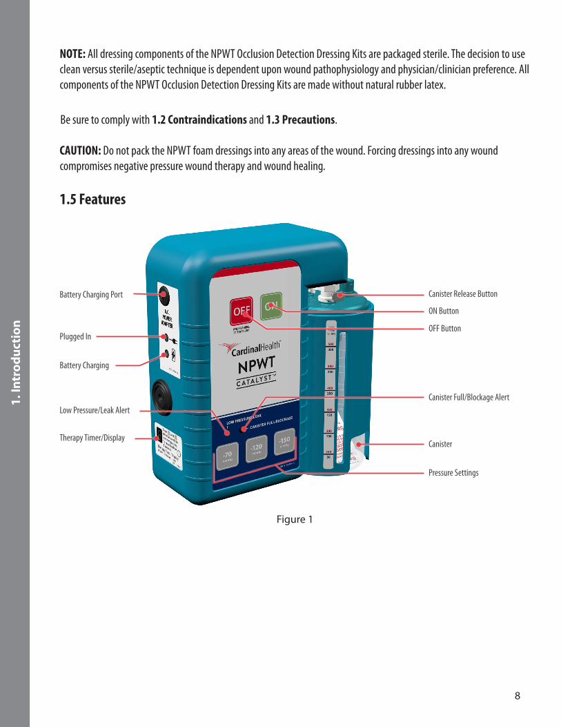
1.5 Features
Canister Release Button
ON Button
OFF Button
Canister Full/Blockage Alert
Canister
Pressure Settings
Battery Charging Port
Plugged In
Battery Charging
Therapy Timer/Display
Low Pressure/Leak Alert
Figure 1

9
1. In
tro
du
ctio
n
Simple Operation: Negative pressure wound therapy activation and changing of Pressure Settings can be accomplished with the push of a button. Pressure Settings can be quickly changed by pressing one of three buttons. Pressure Settings can be locked by the clinical caregiver (4.4 Negative Pressure Wound Therapy Lock/Unlock). Lights next to the Pressure Settings clearly indicate current therapeutic settings.
Lightweight/Impact Resistant: The CATALYST™ weighs 0.9kg (2.0 lb.) for increased mobility. The cover of the CATALYST™ is impact resistant to help prevent damage from dropping.
Noise: The CATALYST™ is quiet in its normal operation with a well-sealed dressing.
Battery: An internal battery in the CATALYST™ provides up to 18 hours of operation from a single full charge. The battery charges while the CATALYST™ is plugged into an outlet with the A.C. Power Adapter. If the battery charge is less than 20 percent, the CATALYST™ “chirps” and the OFF Button flashes.
Power/Charging Status: Indicates the CATALYST™ is charging the internal battery.
Intermittent Mode: The CATALYST™ can be set to operate intermittently (5-minute on/ 2-minute off cycle). The CATALYST™ maintains pressure at -25mmHg during 2-minute “off” cycle to prevent loss of dressing seal.
Alert Display: Automated alerts for Low Pressure/Leak and Canister Full/Blockage. Alerts are both visual and audible. Alerts self-reset once the problem is corrected or can be manually reset by turning the CATALYST™ off and then back on.
IV Pole Adapter: Pole clamp permits the CATALYST™ to be mounted to a wide range of standard IV poles: 2.2 to 5.0cm (0.9 to 2.0 in.) in diameter.
Tubing with SpeedConnect™: Dual lumen tubing set with adhesive SpeedConnect™ makes connection to the dressing easy.
Canisters: 300cc and 500cc canisters with gel solidifiers are available. Both canisters can be used for normal and highly exudating wounds.
CAUTION: Monitor patient status continually. DO NOT USE for infants, pediatrics, or other patients with low fluid volume, or for patients at high risk of hemorrhage.
10
2. C
are
& C
lean
ing
2. Care & Cleaning Carefully read 1.3 Precautions and 1.4 Safety Tips before cleaning the CATALYST™.
Standard Precautions should be used to minimize the risk of infection and contact with contaminated blood or bodily fluids during the dressing changes and cleaning of the CATALYST™. It is important to protect all exposed skin and mucous membranes by using Personal Protective Equipment (PPE). PPE includes:
• Disposable gloves• Protective eyewear• Protective mask
• Disposable impervious gown
2.1 Cleaning Perform a visual inspection of the CATALYST™. Check for any sign of contamination or fluid going into the canister ports. Ensure that the CATALYST™ is functioning properly. If the CATALYST™ is not operating properly, refer to the Troubleshooting guide in 4. Operating Instructions or contact Cardinal Health at 1.866.484.6798.
To help reduce the risk of infection and contact with contaminated blood and bodily fluids, it is recommended to wear personal protective equipment (PPE) when cleaning the CATALYST™.
NOTE: Always follow Standard Precautions. Follow facility protocols regarding clean versus sterile technique.
NOTE: Cleaning of the CATALYST™ must not be performed when the CATALYST™ is connected to a patient or power source. Disconnect the CATALYST™ from the patient and power source before cleaning.
The following cleaning procedure must be performed at least once a week and must be performed between patients.Wipe the CATALYST™ with a diluted solution of 5 milliliters bleach in 1 liter of warm water (approximately 1 teaspoon bleach in 1 quart water). Use a coarse cloth and wring out any excess solution until the cloth is damp and not dripping. Bleach based disinfecting wipes for cleaning medical equipment may also be used.
1. Clean all surfaces of the CATALYST™, including the ports and the A.C. Power Adapter, then allow the solution to air dry on the CATALYST™.
2. If there is visible soilage on the CATALYST™, clean it a second time after the first cleaning has removed the soilage.
3. Wipe down the CATALYST™ with a clean, dry cloth to remove any bleach residue.
4. Visually inspect the CATALYST™ and A.C. Power Adapter for damage. If damage is noted, take the CATALYST™ or the A.C. Power Adapter out of service and replace per protocol.

11
2. C
are
& C
lean
ing
CAUTION: Particular care must be taken when handling undiluted germicide concentrate or chlorine bleach, including proper shielding of eyes. Always mix by adding concentrated germicide or chlorine bleach to the water. NEVER intermix germicides or mix germicides with chlorine bleach. Do not spray liquids directly on to the CATALYST™.
WARNING: Avoid spilling liquid on any part of the CATALYST™. Spilling liquid on the CATALYST™ may cause the CATALYST™ to operate erratically, possibly causing a potential hazard to the patient or clinical caregiver.
Carrying Case and IV Pole AdapterFollow the same procedure as above.
2.2 A.C. Power Adapter Inspection The A.C. Power Adapter should be inspected regularly for damage and/or unusual wear. Replace damaged or worn A.C. Power Adapter immediately. Replacement A.C. Power Adapters are available from Cardinal Health.
WARNING: The CATALYST™ must be used with the supplied A.C. Power Adapter. Use of another adapter/power cord could result in physical hazards, including delayed therapy, electrocution and fire. These hazards could result in injury or death.
12
3. P
atie
nt
Car
e
3. Patient Care Review all Sections of this Clinician User Manual before use of the CATALYST™. Carefully read 1.1 Indications, 1.2 Contraindications, 1.3 Precautions and 1.4 Safety Tips before using the CATALYST™ for patient care.
3.1 Applying the NPWT Occlusion Detection Dressing 1. Cleanse wound according to facility protocols or physician order.
2. Debride all necrotic tissue including eschar and slough.
3. Be certain the wound has achieved hemostasis.
4. Visually examine and palpate wound bed to locate any blood vessels or delicate underlying structure in close proximity.
5. Prepare area around wound to permit adhesion of the polyurethane drape.
NOTE: If peri-wound area is excessively moist or oily, a medical-grade liquid adhesive may improve sealing. For fragile skin, use a skin sealant prior to drape application, or frame the wound with a skin barrier layer, such as a hydrocolloid dressing, the Cardinal Health™ NPWT Drape or the Cardinal Health™ SensiSkin™ NPWT Drape.
6. Take measurements of the wound dimensions and note wound type. Select the appropriate dressing size based on wound assessment. Open the sterile kit to expose the black foam, the tubing with SpeedConnect™ and the drape. Set aside the tubing with SpeedConnect™ and drape from the NPWT Occlusion Detection Dressing Kit.
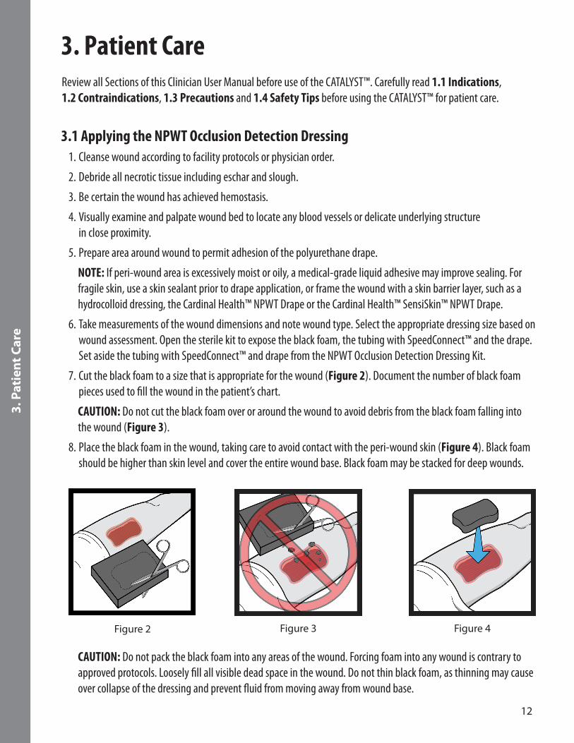
7. Cut the black foam to a size that is appropriate for the wound (Figure 2). Document the number of black foam pieces used to fill the wound in the patient’s chart.
CAUTION: Do not cut the black foam over or around the wound to avoid debris from the black foam falling into the wound (Figure 3).
8. Place the black foam in the wound, taking care to avoid contact with the peri-wound skin (Figure 4). Black foam should be higher than skin level and cover the entire wound base. Black foam may be stacked for deep wounds.
Figure 2 Figure 3 Figure 4
CAUTION: Do not pack the black foam into any areas of the wound. Forcing foam into any wound is contrary to approved protocols. Loosely fill all visible dead space in the wound. Do not thin black foam, as thinning may cause over collapse of the dressing and prevent fluid from moving away from wound base.
13
3. P
atie
nt
Car
e
Use of White Foam
Per clinician’s discretion, white foam may be used in wounds needing extra protection, such as protrusion of bone and in small tunneling and undermining. White foam should be used in an intact, single layer and covered with black foam when not used in small tunnels or in undermining. If the white foam needs to be cut to size, please note that non-linear shape cuts (e.g., curves, spirals, etc.) and straight cuts less than 3cm wide may increase the likelihood that the white foam will tear upon removal.
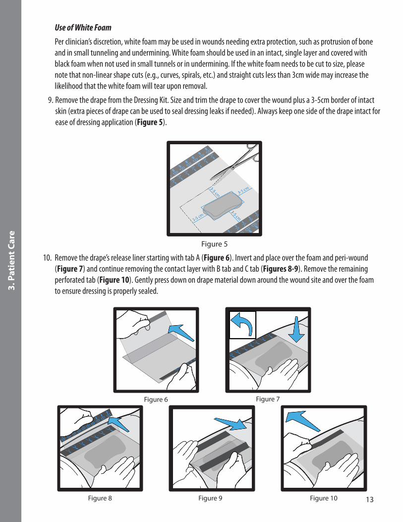
9. Remove the drape from the Dressing Kit. Size and trim the drape to cover the wound plus a 3-5cm border of intact skin (extra pieces of drape can be used to seal dressing leaks if needed). Always keep one side of the drape intact for ease of dressing application (Figure 5).
Figure 5
10. Remove the drape’s release liner starting with tab A (Figure 6). Invert and place over the foam and peri-wound (Figure 7) and continue removing the contact layer with B tab and C tab (Figures 8-9). Remove the remaining perforated tab (Figure 10). Gently press down on drape material down around the wound site and over the foam to ensure dressing is properly sealed.
Figure 6
Figure 8 Figure 9 Figure 10
Figure 7
14
3. P
atie
nt
Car
e
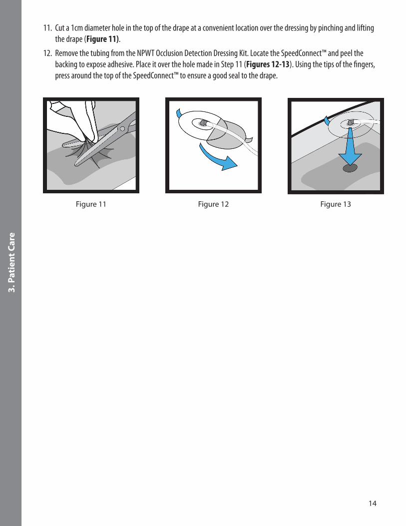
11. Cut a 1cm diameter hole in the top of the drape at a convenient location over the dressing by pinching and lifting the drape (Figure 11).
12. Remove the tubing from the NPWT Occlusion Detection Dressing Kit. Locate the SpeedConnect™ and peel the backing to expose adhesive. Place it over the hole made in Step 11 (Figures 12-13). Using the tips of the fingers, press around the top of the SpeedConnect™ to ensure a good seal to the drape.
Figure 11 Figure 12 Figure 13
15
3. P
atie
nt
Car
e
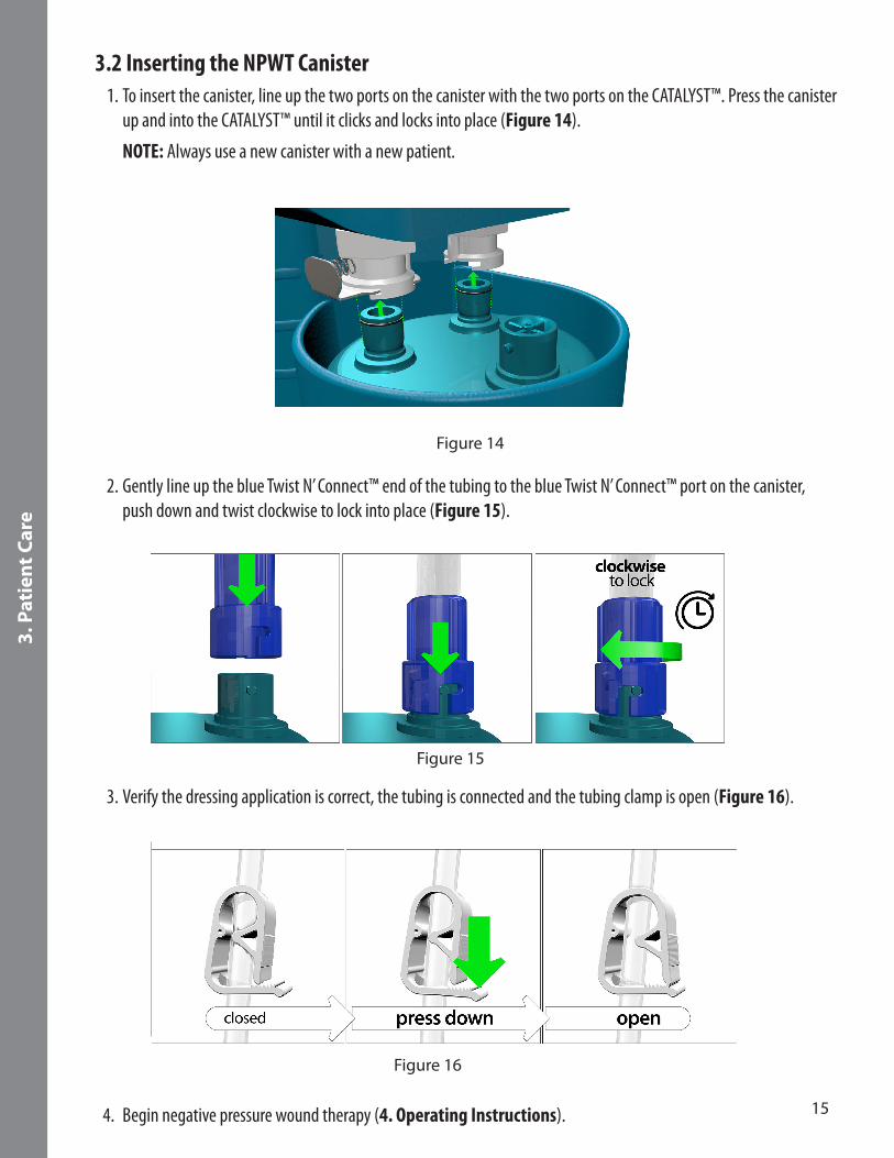
3.2 Inserting the NPWT Canister 1. To insert the canister, line up the two ports on the canister with the two ports on the CATALYST™. Press the canister
up and into the CATALYST™ until it clicks and locks into place (Figure 14).
NOTE: Always use a new canister with a new patient.
Figure 14
2. Gently line up the blue Twist N’ Connect™ end of the tubing to the blue Twist N’ Connect™ port on the canister, push down and twist clockwise to lock into place (Figure 15).
Figure 15
3. Verify the dressing application is correct, the tubing is connected and the tubing clamp is open (Figure 16).
Figure 16
4. Begin negative pressure wound therapy (4. Operating Instructions).
16
3. P
atie
nt
Car
e
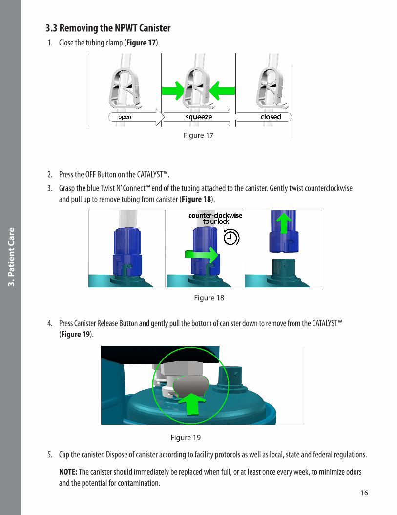
3.3 Removing the NPWT Canister 1. Close the tubing clamp (Figure 17).
Figure 17
2. Press the OFF Button on the CATALYST™.
3. Grasp the blue Twist N’ Connect™ end of the tubing attached to the canister. Gently twist counterclockwise and pull up to remove tubing from canister (Figure 18).
Figure 18
4. Press Canister Release Button and gently pull the bottom of canister down to remove from the CATALYST™ (Figure 19).
Figure 19
5. Cap the canister. Dispose of canister according to facility protocols as well as local, state and federal regulations. NOTE: The canister should immediately be replaced when full, or at least once every week, to minimize odors and the potential for contamination.

17
3. P
atie
nt
Car
e
3.4 Delivering Simultaneous Irrigation™ TechnologyCardinal Health offers two irrigation tubing set options that deliver irrigation and negative pressure wound therapy simultaneously. The NPWT Irrigation Tubing with SpeedConnect™ consists of a single-lumen tubing with SpeedConnect™ and a luer lock connector to connect to the irrigation of choice. The NPWT Irrigation Delivery Set consists of a single-lumen tubing with SpeedConnect™ and an irrigation delivery bag that allows the irrigation of choice to be delivered through the delivery bag. Both tubing options deliver irrigation solution to the wound.
Precautions
• Simultaneous Irrigation™ Technology can be utilized with the CATALYST™. Appropriate solutions for Simultaneous Irrigation™ Technology may include normal saline or other solutions indicated for topical wound treatment.
• Any solution cleared for use in topical wound irrigation can be used as the wound irrigant.• Various topical agents, such as hydrogen peroxide and solutions containing alcohol, are not intended for
extended tissue contact. If in doubt about the appropriateness of using a solution with the CATALYST™, contact the solution’s manufacturer.
• Do not apply solutions in conflict with the manufacturer’s instructions for use.• During irrigation therapy, the dressing is a closed system and is NOT vented to atmosphere.• Do not use where temperature of fluid could cause and adverse reaction, such as a change in patient’s core
body temperature.• During irrigation therapy, check the irrigation bag periodically to ensure proper fluid delivery. In addition, when
a canister fills with fluid, it should be immediately replaced as irrigation fluid and wound exudate is not removed from the wound if the canister is full.
18
3. P
atie
nt
Car
e
Instructions
1. Make sure the irrigation fluid supply remains clamped off until the therapy is started and target pressure is achieved.
2. Obtain a physician order for irrigation solution type and delivery rate.
3. Apply NPWT Occlusion Detection Dressing (3.1 Applying the NPWT Occlusion Detection Dressing).
4. Connect NPWT Irrigation Tubing attachment to the irrigation solution container or use the NPWT Irrigation Delivery Set, which incorporates an irrigation bag with a tubing set together. Close the irrigation clamp completely.
5. Hang irrigation bag on IV pole higher than the wound.
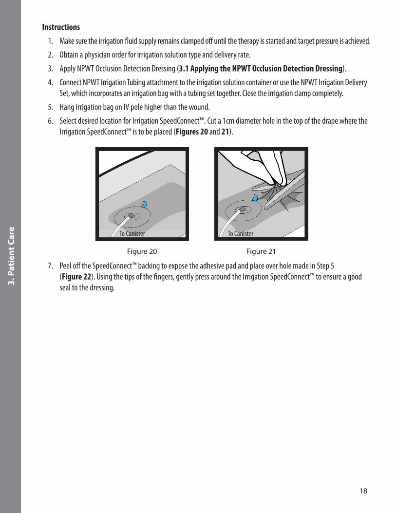
6. Select desired location for Irrigation SpeedConnect™. Cut a 1cm diameter hole in the top of the drape where the Irrigation SpeedConnect™ is to be placed (Figures 20 and 21).
Figure 21
To Canister
Figure 20
To Canister
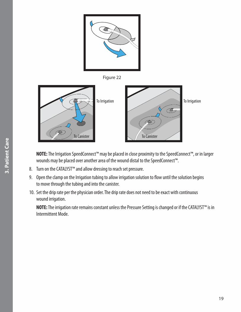
7. Peel off the SpeedConnect™ backing to expose the adhesive pad and place over hole made in Step 5 (Figure 22). Using the tips of the fingers, gently press around the Irrigation SpeedConnect™ to ensure a good seal to the dressing.
19
3. P
atie
nt
Car
e
Figure 22
To Irrigation
To Canister To Canister
To Irrigation
NOTE: The Irrigation SpeedConnect™ may be placed in close proximity to the SpeedConnect™, or in larger wounds may be placed over another area of the wound distal to the SpeedConnect™.
8. Turn on the CATALYST™ and allow dressing to reach set pressure.
9. Open the clamp on the Irrigation tubing to allow irrigation solution to flow until the solution begins to move through the tubing and into the canister.
10. Set the drip rate per the physician order. The drip rate does not need to be exact with continuous wound irrigation.
NOTE: The irrigation rate remains constant unless the Pressure Setting is changed or if the CATALYST™ is in Intermittent Mode.

20
3. P
atie
nt
Car
e
3.5 NPWT Occlusion Detection Y Connector NPWT Occlusion Detection Y Connector is designed to connect two Cardinal Health™ NPWT Occlusion Detection Dressings with Twist N’ Connect™ ports to a single Cardinal Health™ NPWT Occlusion Detection canister in a CATALYST™ device.
WARNING: When using the Occlusion Detection Y Connector to treat multiple wound sites, the CATALYST™ only detects blockages in the wound site connected to the primary Occlusion Detection Y Connector port (Figure 23).
WARNING: A blockage in the wound site connected to the secondary Occlusion Detection Y Connector port will not be detected by the CATALYST™.
NOTE: The Occlusion Detection tubing should not be draped on the floor. Minimize draping by ensuring tubing remains level with or above the pump.
Instructions
1. After placement of dressings (see 3.1 Applying the NPWT Occlusion Detection Dressing) and insertion of the canister into the CATALYST™ (see 3.2 Inserting the NPWT Canister), line up the Twist N’ Connect™ canister port to the bottom of the Occlusion Detection Y Connector, push down and twist clockwise to lock into place.
2. Connect the Twist N’ Connect™ tubing for each wound to the bifurcated end of the Y Connector (Figure 23). NOTE: Connect the NPWT Occlusion Detection tubing from the primary dressing to the primary port for occlusion detection.
Figure 23
3. Verify the dressing application is correct, the primary wound, secondary wound and canister ports are properly connected and the tubing clamps are open.
4. Begin negative pressure wound therapy.
Change/Disposal
Replace the Occlusion Detection Y Connector with each dressing change. See 1.4 Safety Tips.
WARNING: Do not connect infected wounds with non-infected wounds.
WARNING: Do not use an Occlusion Detection Y Connector to connect wounds that would be optimally treated with differing pressure settings.
If CATALYST™ alerts, see 4.9 Troubleshooting.
21
3. P
atie
nt
Car
e
3.6 Removing the NPWT Occlusion Detection Dressing Carefully read 1.4 Safety Tips before removing the dressing.
NOTE: Wounds must be carefully monitored at regular intervals. In a non-infected wound, dressings should be changed every 48 to 72 hours; as determined by the clinician. For infected wounds, dressings may need to be changed more often than 48 to 72 hours based on a clinical evaluation of the wound.
Standard Precautions should be used to minimize the risk of infection and contact with contaminated blood or bodily fluids during the dressing changes. It is important to protect all exposed skin and mucous membranes by using Personal Protective Equipment (PPE). PPE includes:
• Disposable gloves• Protective eyewear• Protective mask• Disposable impervious gown
1. With the CATALYST™ on, lift a corner of the drape to allow air to enter the system, moving any fluid in the tubing into the canister.
2. Close tubing clamp (Figure 16).
NOTE: Only applicable if using NPWT Occlusion Detection Dressing.
3. Press the OFF Button on the CATALYST™.
4. Remove the tubing by holding the blue Twist N’ Connect™ end of the tubing, gently twist counterclockwise and remove the tubing from the canister (Figure 17).
5. Gently stretch the drape laterally and slowly pull up and away from skin. Lateral stretching of the drape or dressing will help release the adhesive and minimize trauma to the patient’s skin.
NOTE: If the patient complains of discomfort during the dressing change, consider pre-medication, use of a non-adherent wound contact layer prior to foam placement in the wound or irrigation of a topical anesthetic agent such as 1 percent Lidocaine prior to dressing removal.
6. Remove foam from wound. Make sure that the number of pieces removed from the wound matches the number of pieces that were placed into the wound. If the numbers do not match, further procedures may have to be performed to resolve the difference.
7. Discard used foam, tubing, canister, and drape in accordance with applicable rules, regulations and infection control protocols and always follow Standard Precautions.
22
3. P
atie
nt
Car
e
3.7 Disposal of Used ComponentsAfter patient use, all used disposable components of the system should be treated as contaminated.
These may include:• The NPWT foam dressing and polyurethane drape• The canister• The tubing• Irrigation tubing set and irrigation delivery set
Dispose of all used components in accordance with facility protocols as well as local, state and federal regulations.
23
4. O
per
atin
g In
stru
ctio
ns
4. Operating Instructions Carefully read 1.3 Precautions and 1.4 Safety Tips before attempting to operate and adjust the CATALYST™.
CAUTION: The CATALYST™ must only be used with the supplied A.C. Power Adapter. Use of any other adapter/power cord could create a shock hazard for the patient or caregiver, cause fire and/or severely damage the CATALYST™. If a replacement A.C. Power Adapter is needed, call Cardinal Health at 1.866.484.6798.
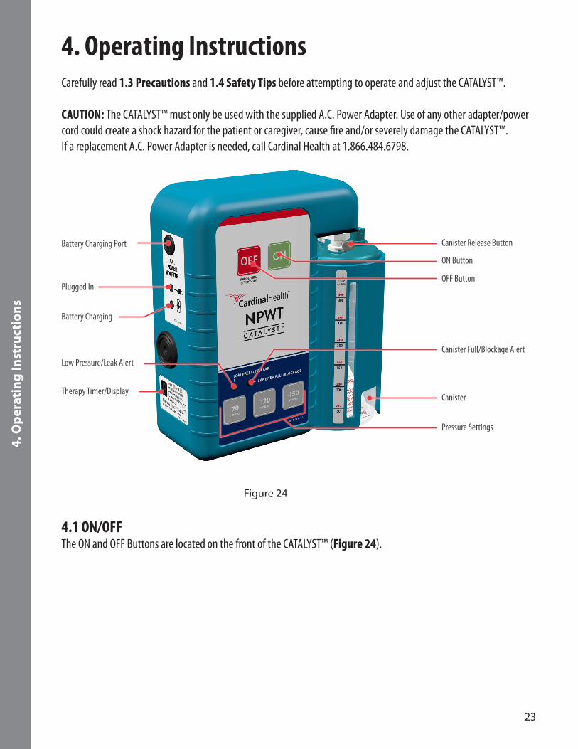
Canister Release Button
ON Button
OFF Button
Canister Full/Blockage Alert
Canister
Pressure Settings
Battery Charging Port
Plugged In
Battery Charging
Therapy Timer/Display
Low Pressure/Leak Alert
Figure 24
4.1 ON/OFF The ON and OFF Buttons are located on the front of the CATALYST™ (Figure 24).
24
4. O
per
atin
g In
stru
ctio
ns
4.2 Power-Up Procedure 1. Verify the dressing is correct, the tubing is connected and clamp is open.
2. Keep the CATALYST™ upright. The CATALYST™ can be placed on a table, or attached to an IV pole using the IV pole adapter, but it is recommended to keep level with or below the wound. CAUTION: The clamp on the IV pole adapter should only be used on poles that are in excess of 2.2cm (0.9 in.)diameter and are securely attached to a suitable stand. To ensure stability of the CATALYST™ on the IV pole, ensure the clamp is no higher than two times the width of the pole base. The clamp should be tightened to ensure that the CATALYST™ cannot slide down the pole.
3. Press the ON Button. All indicators light up for 1 second during the power-on self-test, after which, the ON Button stays green.
4. The dressing should slowly collapse, indicating the presence of negative pressure. Once dressing integrity is verified, adjust the CATALYST™ for desired Pressure Setting.
NOTE: It is recommended that the CATALYST™ is connected to the A.C. Power Adapter while attempting to obtain an initial dressing seal.
5. Carefully check dressing for leaks and repair with additional drape, if necessary.
6. The CATALYST™ should be operated at least 22 hours out of every 24-hour period. Remove the dressing if the negative wound pressure therapy is terminated or the CATALYST™ is off for more than 2 hours in a 24-hour period.
4.3 Negative Pressure Wound Therapy Setting AdjustmentCAUTION: Only a physician can prescribe the proper settings and irrigation protocols for the CATALYST™. Failure to follow instructions, adjusting settings or performing negative pressure wound therapy without the express direction and/or supervision of your trained clinical caregiver may lead to improper performance and possible serious or fatal injury.
There are three Pressure Settings: -70mmHg, -120mmHg, -150mmHg (Figure 24).
When the CATALYST™ is turned on, the default Pressure Setting is -120mmHg, unless therapy Pressure Setting has been locked previously by the clinical caregiver, see 4.4 Negative Pressure Wound Therapy Selection Lock/Unlock.
To change the Pressure Setting, press the desired Pressure Setting Button found on the front of the CATALYST™.
The selected Pressure Setting Button flashes, indicating the selection has been made. The Pressure Setting Button continues flashing until the desired pressure has been achieved at which time the button is solid. If the Pressure Setting Button begins to flash during therapy, the CATALYST™ is unable to maintain the therapeutic setting.
25
4. O
per
atin
g In
stru
ctio
ns
4.4 Negative Pressure Wound Therapy Selection Lock/UnlockThe CATALYST™ has a Pressure Setting lockout feature designed to prevent unauthorized individuals from changing thePressure Setting.
LockingTo lock the CATALYST™, press and hold the desired Pressure Setting for 3 seconds until three audible beeps are heard. The CATALYST™ is locked. Pressing any other Pressure Setting results in three beeps with no change in Pressure Setting. The Pressure Setting remains at the selected pressure even if the CATALYST™ is powered off and on. The CATALYST™ remains locked.
UnlockingTo unlock the CATALYST™, press and hold the selected Pressure Setting Button until three audible beeps are heard. The CATALYST™ is now unlocked and Pressure Settings can be changed. When the CATALYST™ is powered off and on, it remains unlocked and automatically reverts to the default setting of -120mmHg.
4.5 Intermittent Mode ON/OFFThe CATALYST™ can operate in Intermittent Mode with a 5-minute “ON” and 2-minute “OFF” cycle.
To turn the Intermittent Mode on, press and hold the desired Pressure Setting Button then press the OFF Button at the same time. The CATALYST™ beeps twice and the ON Button begins flashing, indicating the CATALYST™ is now operating in Intermittent Mode. Release both buttons.
To turn the Intermittent Mode off, repeat the above steps. The CATALYST™ produces a single long beep and the ON Button is solid. The mode setting is memorized in the CATALYST™ when the power is turned off and on. During intermittent operation, the CATALYST™ provides desired pressure during the “ON” part of the cycle and approximately -25mmHg during the “OFF” part of the cycle. Cycling to this lower pressure while the CATALYST™ is off helps maintain the integrity of the drape seal.
4.6 Therapy Timer Display The CATALYST™ has an LED Therapy Timer Display for displaying two types of therapy timers: Total time accumulated by the CATALYST™ (non-resettable) and patient usage therapy time (resettable). The Therapy Timer Display uses the format: “d: days, H: hours, -: mins” and data is displayed sequentially on the display. When the CATALYST™ is first turned on, the total time is displayed. This timer cannot be reset and accumulates time as the CATALYST™ is used.
After the CATALYST™ has displayed the total time and at any time it is operating, pressing the ON Button and -120mmHg Button at the same time starts the display of therapy time. To reset the therapy time, press and hold the ON Button and -120mmHg Button until the CATALYST™ beeps three times and the Therapy Time Display indicates “d: 0, H: 00, -: 00”.
26
4. O
per
atin
g In
stru
ctio
ns
4.7 Alert VolumeThe volume of the alert can be adjusted. To increase the alert volume, press and hold the ON Button while simultaneously pressing the -150mmHg Button. To decrease the alert volume, press and hold the ON Button while simultaneously pressing the -70mmHg Button. The Therapy Timer Display on the side of the CATALYST™ shows the volume level which ranges from 1 to 5. The factory set alert volume level is 2.
4.8 Battery Operation NOTE: The CATALYST™ continues to operate while the internal battery is charging.
Battery LifeThe battery life of the CATALYST™ with a fully-charged battery and a well-sealed dressing is up to 18 hours. The actual life is dependent on the integrity of the dressing. A leak in the dressing and using Intermittent Mode can reduce overall battery longevity.
Low Battery AlertWhile running on battery, a Low Battery alert “chirps” every 10 seconds and the OFF Button flashes when remaining capacity of the battery is less than 20 percent (4.9 Troubleshooting). Typically, the CATALYST™ continues to operate for approximately 1 hour after the Low Battery Alert is activated.
Low Battery ShutoffIf the battery charge falls below a critical level, the CATALYST™ shuts off and negative pressure wound therapy is discontinued. At this point, the CATALYST™ must be plugged into an outlet using the A.C. Power Adapter for negative pressure wound therapy to resume. Once the A.C. Power Adapter is plugged in, pressing the ON Button restarts the CATALYST™.

27
4. O
per
atin
g In
stru
ctio
ns
Recharging the BatteryPlug the A.C. Power Adapter into the Battery Charging Port on the left side of the CATALYST™ (Figure 25). Plug the A.C. Power Adapter into a wall outlet.
Figure 25
When the CATALYST™ is connected to an outlet, the green light next to the Plugged In symbol lights up (Figure 25). The yellow light next to the Battery Charging symbol lights up when the battery is charging.
NOTE: If the CATALYST™ is plugged in and the green light does not turn on, check to make sure the outlet is working properly.
Figure 26
Once the battery is fully charged, the yellow light next to the Battery Charging symbol turns off, showing the battery is fully charged. When the A.C. Power Adapter is disconnected from the outlet, the CATALYST™ automatically switches over to the internal battery and continues to operate.
Average Time for RechargingAfter approximately 2 hours of charging, the CATALYST™ achieves 80 percent of the total battery capacity. To ensure that the battery is fully charged, the CATALYST™ should be connected to an outlet for approximately 3 hours.

28
4. O
per
atin
g In
stru
ctio
ns
4.9 Troubleshooting Clearing an Alert Condition To manually reset an alert, turn the CATALYST™ off then back on. The alert clears when the power is cycled.
What you see or hear Problem What to do More information
OFF Button is flashing.
Single beep.
The battery is low and has approximately 30 minutes before the battery will be too low to support continued operation of the CATALYST™.
• Plug in the CATALYST™. A green light shows next to Plugged In and an amber light next to Battery Charging indicates that power is going to the CATALYST™. The amber light turns off after the battery is fully charged.
Use only the A.C. Power Adapter that came with the CATALYST™.
If alert continues or replacement A.C. Power Adapter is needed, call Cardinal Health at 1.866.484.6798 for more assistance.
LOW PRESSURE/LEAK indicator is lit.
Single beep.
Pressure Setting Button is flashing.
CATALYST™ is making more noise.
There is an air leak in either the dressing or the tubing connections.
Leaks often occur over areas of moist skin, creases or folds in skin and wrinkles in the drape. They can occur if the drape snags on clothing or bed sheets.
• Close the clamp.
• If the Low Pressure/Leak light stops, there is a leak between the clamp and the dressing — often in the dressing. Reopen the clamp before addressing the leak.
• Gently press around drape to check for leaks. If leak is found, patch with extra drape material.
• If Low Pressure/Leak alert continues, there is a leak between the clamp and the CATALYST™. Check the tubing connection at the canister. If using an NPWT Occlusion Detection Y Connector, check connections between tubing and Y Connector. Check to ensure the canister is fully seated and locked. Check for cracks in the canister or lid separation. If found, replace the canister.
• Open the clamp.
Once the leak is found and sealed, the alert resets, the Pressure Setting quits flashing and the CATALYST™ becomes quiet.

29
4. O
per
atin
g In
stru
ctio
ns
What you see or hear Problem What to do More information
CANISTER FULL/BLOCKAGE indicator is lit.
Single beep.
The canister is full or there may be a blockage in the tubing and/or dressing.
• Visually assess the canister to see if full. If the canister is full, change the canister.
• If the canister is not full, turn the CATALYST™ off by pressing the OFF
Button and then turn the CATALYST™ back on to resume therapy.
• If changing the canister and/or turning the CATALYST™ off and then back on does not resolve the alert, look for occlusions in the tubing or possibly in the dressing. If changing the canister and/or turning the CATALYST™ off and then back on does not resolve the alert, look for kinks in the tubing (including Y Connector if used) and unkink. If alert is still not resolved, look for occlusions in the tubing or possibly the dressing. Change the tubing and/or dressing as needed to resolve the alert.
The Canister Full/ Blockage alert begins when the canister is 90 percent full, but the CATALYST™ continues to work until the canister completely fills.
If the CATALYST™ is placed on its front, fluid causes a false Canister Full/ Blockage alert and the canister must be changed.
If alert continues, call Cardinal Health at 1.866.484.6798 for more assistance.
Pressure will not change.
Pressure Setting has been locked.
Unlock the CATALYST™.
CATALYST™ is quiet and fluid is not moving in the tubing.
This is NOT a problem. The dressing has a good seal and the CATALYST™ is maintaining target pressure.
No action needed. Change the CATALYST™ to Intermittent Mode to move fluid in the tubing to the canister.
ON Button is flashing.
The CATALYST™ is making more noise every 5 minutes.
This is NOT a problem. The CATALYST™ is in Intermittent Mode.
No action needed. Intermittent Mode maintains target pressure for 5 minutes and decreases to -25mmHg for 2 minutes.
To change from Continuous to Intermittent Mode, press and hold the Pressure Setting Button and tap the OFF Button. Repeat to change back to Continuous Mode.
NOTE: If an alert persists and cannot be resolved, please contact Cardinal Health at 1.866.484.6798.CAUTION: In the event of an emergency, please contact the treating physician, caregiver or emergency responders.

30
5. S
ymb
ols
Glo
ssar
y
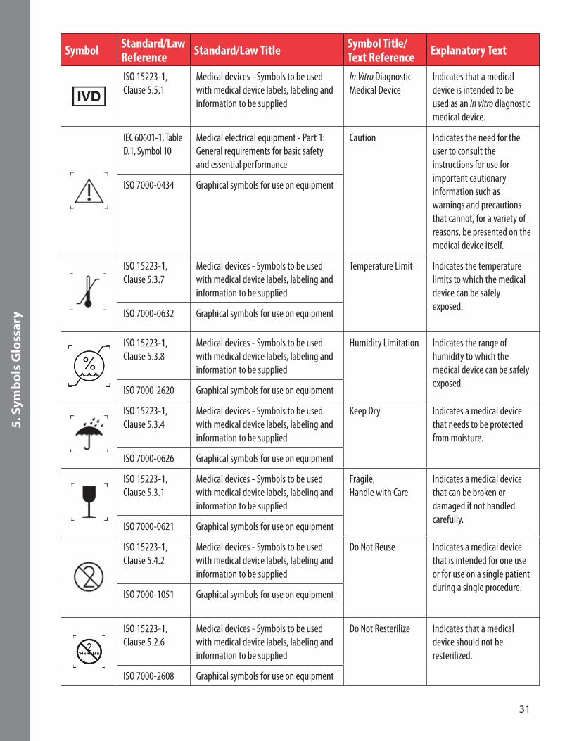
5. Symbols Glossary
Symbols Recognized by Standard/Law
Symbol Standard/Law Reference Standard/Law Title Symbol Title/
Text Reference Explanatory Text
ISO 13225-1, Clause 5.1.1
Medical devices - Symbols to be used with medical device labels, labeling and information to be supplied
Manufacturer Indicates the medical device manufacturer.
ISO 7000-3082 Graphical symbols for use on equipment
ISO 15223-1, Clause 5.1.3
Medical devices - Symbols to be used with medical device labels, labeling and information to be supplied
Date of Manufacture Indicates the date when the medical device was manufactured.
ISO 7000-2497 Graphical symbols for use on equipment
EN 60417-6049 Graphical symbols for use on equipment Country of Origin To identify the country of manufacture of products. To identify country abbreviation, see https://www.iso.org/obp/ui/#search.
ISO 3166-1 Codes for the representation of names of countries and their subdivisions - Part 1: Country Codes
ISO 15223-1, Clause 5.1.2
Medical devices - Symbols to be used with medical device labels, labeling and information to be supplied
Authorized European Representative
Indicates the Authorized Representative in the European Union.
ISO 15223-1, Clause 5.1.6
Medical devices - Symbols to be used with medical device labels, labeling and information to be supplied
Catalogue orModel Number
Indicates the manufacturer’s catalogue number so the device can be identified.
ISO 7000-2493 Graphical symbols for use on equipment
ISO 15223-1, Clause 5.1.7
Medical devices - Symbols to be used with medical device labels, labeling and information to be supplied
Serial Number Indicates the manufacturer’s serial number so that a specific device can be identified.
ISO 7000-2498 Graphical symbols for use on equipment
ISO 15223-1, Clause 5.1.5
Medical devices - Symbols to be used with medical device labels, labeling and information to be supplied
Batch/Lot Code Indicates the manufacturer’s batch/lot code so that the batch or lot can be identified.
ISO 7000-2492 Graphical symbols for use on equipment
ISO 15223-1, Clause 5.1.4
Medical devices - Symbols to be used with medical device labels, labeling and information to be supplied
Use by Date Indicates the date after which the medical device is not to be used.
ISO 7000-2607 Graphical symbols for use on equipment
31
5. S
ymb
ols
Glo
ssar
y
Symbol Standard/Law Reference Standard/Law Title Symbol Title/
Text Reference Explanatory Text
ISO 15223-1, Clause 5.5.1
Medical devices - Symbols to be used with medical device labels, labeling and information to be supplied
In Vitro Diagnostic Medical Device
Indicates that a medical device is intended to be used as an in vitro diagnostic medical device.
IEC 60601-1, Table D.1, Symbol 10
Medical electrical equipment - Part 1: General requirements for basic safety and essential performance
Caution Indicates the need for the user to consult the instructions for use for important cautionaryinformation such as warnings and precautions that cannot, for a variety of reasons, be presented on the medical device itself.
ISO 7000-0434 Graphical symbols for use on equipment
ISO 15223-1, Clause 5.3.7
Medical devices - Symbols to be used with medical device labels, labeling and information to be supplied
Temperature Limit Indicates the temperature limits to which the medical device can be safely exposed.
ISO 7000-0632 Graphical symbols for use on equipment
ISO 15223-1, Clause 5.3.8
Medical devices - Symbols to be used with medical device labels, labeling and information to be supplied
Humidity Limitation Indicates the range of humidity to which the medical device can be safely exposed.
ISO 7000-2620 Graphical symbols for use on equipment
ISO 15223-1, Clause 5.3.4
Medical devices - Symbols to be used with medical device labels, labeling and information to be supplied
Keep Dry Indicates a medical device that needs to be protected from moisture.
ISO 7000-0626 Graphical symbols for use on equipment
ISO 15223-1, Clause 5.3.1
Medical devices - Symbols to be used with medical device labels, labeling and information to be supplied
Fragile, Handle with Care
Indicates a medical device that can be broken or damaged if not handled carefully.
ISO 7000-0621 Graphical symbols for use on equipment
ISO 15223-1, Clause 5.4.2
Medical devices - Symbols to be used with medical device labels, labeling and information to be supplied
Do Not Reuse Indicates a medical device that is intended for one use or for use on a single patient during a single procedure.
ISO 7000-1051 Graphical symbols for use on equipment
ISO 15223-1, Clause 5.2.6
Medical devices - Symbols to be used with medical device labels, labeling and information to be supplied
Do Not Resterilize Indicates that a medical device should not be resterilized.
ISO 7000-2608 Graphical symbols for use on equipment

32
5. S
ymb
ols
Glo
ssar
y
Symbol Standard/Law Reference Standard/Law Title Symbol Title/
Text Reference Explanatory Text
ISO 15223-1, Clause 5.2.1
Medical devices - Symbols to be used with medical device labels, labeling and information to be supplied
Sterile Indicates a medical device that has been subjected to a sterilization process.
ISO 7000-2499 Graphical symbols for use on equipment
ISO 15223-1, Clause 5.2.2
Medical devices - Symbols to be used with medical device labels, labeling and information to be supplied
Sterile Using Aseptic Techniques
Indicates medical device that has been sterilized by using accepted aseptic technique.
ISO 7000-2500 Graphical symbols for use on equipment
ISO 15223-1, Clause 5.2.3
Medical devices - Symbols to be used with medical device labels, labeling and information to be supplied
Sterilized by Ethylene Oxide
Sterilized by ethylene oxide
ISO 7000-2501 Graphical symbols for use on equipment
ISO 15223-1, Clause 5.2.4
Medical devices - Symbols to be used with medical device labels, labeling and information to be supplied
Sterilized Using Irradiation
Indicates a medical device that has been sterilized using irradiation.
ISO 7000-2502 Graphical symbols for use on equipment
ISO 15223-1, Clause 5.2.5
Medical devices - Symbols to be used with medical device labels, labeling and information to be supplied
Sterilized Using Steam or Dry Heat
Indicates a medical device that has been sterilized using steam or dry heat.
ISO 7000-2503 Graphical symbols for use on equipment
ISO 15223-1, Clause 5.2.9
Medical devices - Symbols to be used with medical device labels, labeling and information to be supplied
Sterile Fluid Path To identify the presence of a sterile fluid path within the medical device when other parts of the medical device are not necessarily supplied sterile.
ISO 7000-3084 Graphical symbols for use on equipment
ISO 15223-1, Clause 5.3.2
Medical devices - Symbols to be used with medical device labels, labeling and information to be supplied
Keep Away from Sunlight
Indicates a medical device that needs protection from light sources.
ISO 7000-0624 Graphical symbols for use on equipment
ISO 15223-1, Clause 5.2.7
Medical devices - Symbols to be used with medical device labels, labeling and information to be supplied
Non-sterile Indicates a medical device that has not been subjected to a sterilization process.
ISO 7000-2609 Graphical symbols for use on equipment
33
5. S
ymb
ols
Glo
ssar
y
Symbol Standard/Law Reference Standard/Law Title Symbol Title/
Text Reference Explanatory Text
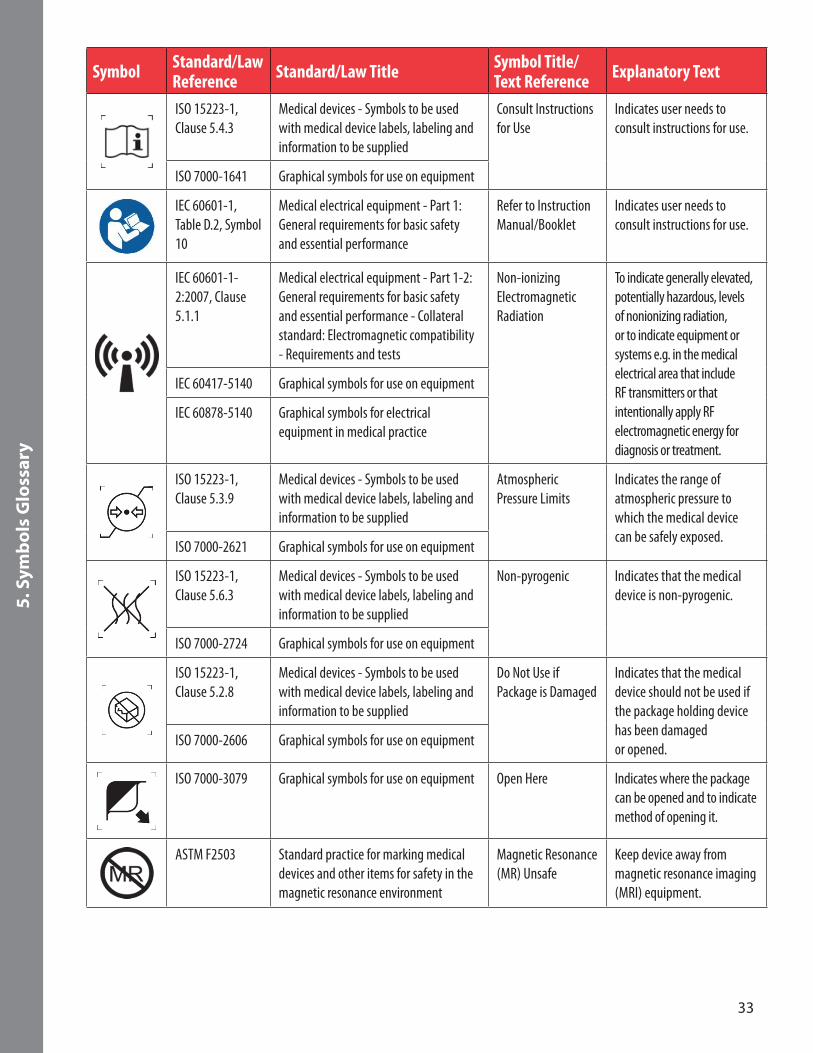
ISO 15223-1, Clause 5.4.3
Medical devices - Symbols to be used with medical device labels, labeling and information to be supplied
Consult Instructions for Use
Indicates user needs to consult instructions for use.
ISO 7000-1641 Graphical symbols for use on equipment
IEC 60601-1, Table D.2, Symbol 10
Medical electrical equipment - Part 1: General requirements for basic safety and essential performance
Refer to Instruction Manual/Booklet
Indicates user needs to consult instructions for use.
IEC 60601-1-2:2007, Clause 5.1.1
Medical electrical equipment - Part 1-2: General requirements for basic safety and essential performance - Collateral standard: Electromagnetic compatibility - Requirements and tests
Non-ionizing Electromagnetic Radiation
To indicate generally elevated, potentially hazardous, levels of nonionizing radiation, or to indicate equipment or systems e.g. in the medical electrical area that include RF transmitters or that intentionally apply RF electromagnetic energy for diagnosis or treatment.
IEC 60417-5140 Graphical symbols for use on equipment
IEC 60878-5140 Graphical symbols for electrical equipment in medical practice
ISO 15223-1, Clause 5.3.9
Medical devices - Symbols to be used with medical device labels, labeling and information to be supplied
Atmospheric Pressure Limits
Indicates the range of atmospheric pressure to which the medical device can be safely exposed.
ISO 7000-2621 Graphical symbols for use on equipment
ISO 15223-1, Clause 5.6.3
Medical devices - Symbols to be used with medical device labels, labeling and information to be supplied
Non-pyrogenic Indicates that the medical device is non-pyrogenic.
ISO 7000-2724 Graphical symbols for use on equipment
ISO 15223-1, Clause 5.2.8
Medical devices - Symbols to be used with medical device labels, labeling and information to be supplied
Do Not Use if Package is Damaged
Indicates that the medical device should not be used if the package holding device has been damaged or opened.ISO 7000-2606 Graphical symbols for use on equipment
ISO 7000-3079 Graphical symbols for use on equipment Open Here Indicates where the package can be opened and to indicate method of opening it.
ASTM F2503 Standard practice for marking medical devices and other items for safety in the magnetic resonance environment
Magnetic Resonance (MR) Unsafe
Keep device away from magnetic resonance imaging (MRI) equipment.
34
5. S
ymb
ols
Glo
ssar
y
Symbol Standard/Law Reference Standard/Law Title Symbol Title/
Text Reference Explanatory Text
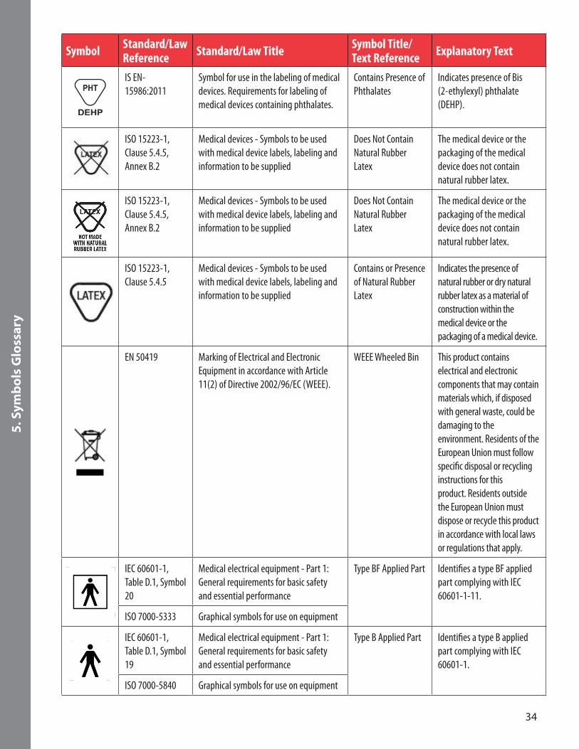
IS EN-15986:2011
Symbol for use in the labeling of medical devices. Requirements for labeling of medical devices containing phthalates.
Contains Presence of Phthalates
Indicates presence of Bis (2-ethylexyl) phthalate (DEHP).
ISO 15223-1, Clause 5.4.5, Annex B.2
Medical devices - Symbols to be used with medical device labels, labeling and information to be supplied
Does Not Contain Natural Rubber Latex
The medical device or the packaging of the medical device does not contain natural rubber latex.
ISO 15223-1, Clause 5.4.5, Annex B.2
Medical devices - Symbols to be used with medical device labels, labeling and information to be supplied
Does Not Contain Natural Rubber Latex
The medical device or the packaging of the medical device does not contain natural rubber latex.
ISO 15223-1, Clause 5.4.5
Medical devices - Symbols to be used with medical device labels, labeling and information to be supplied
Contains or Presence of Natural Rubber Latex
Indicates the presence of natural rubber or dry natural rubber latex as a material of construction within the medical device or the packaging of a medical device.
EN 50419 Marking of Electrical and Electronic Equipment in accordance with Article 11(2) of Directive 2002/96/EC (WEEE).
WEEE Wheeled Bin This product contains electrical and electronic components that may contain materials which, if disposed with general waste, could be damaging to the environment. Residents of the European Union must follow specific disposal or recycling instructions for this product. Residents outside the European Union must dispose or recycle this product in accordance with local laws or regulations that apply.
IEC 60601-1, Table D.1, Symbol 20
Medical electrical equipment - Part 1: General requirements for basic safety and essential performance
Type BF Applied Part Identifies a type BF applied part complying with IEC 60601-1-11.
ISO 7000-5333 Graphical symbols for use on equipment
IEC 60601-1, Table D.1, Symbol 19
Medical electrical equipment - Part 1: General requirements for basic safety and essential performance
Type B Applied Part Identifies a type B applied part complying with IEC 60601-1.
ISO 7000-5840 Graphical symbols for use on equipment
35
5. S
ymb
ols
Glo
ssar
y
Symbol Standard/Law Reference Standard/Law Title Symbol Title/
Text Reference Explanatory Text
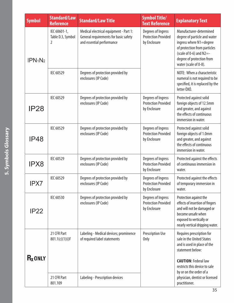
IEC 60601-1, Table D.3, Symbol 2
Medical electrical equipment - Part 1: General requirements for basic safety and essential performance
Degrees of Ingress Protection Provided by Enclosure
Manufacturer-determined degree of particle and water ingress where N1=degree of protection from particles (scale of 0-6) and N2=-degree of protection from water (scale of 0-8).
IEC 60529 Degrees of protection provided by enclosures (IP Code)
NOTE: When a characteristic numeral is not required to be specified, it is replaced by the letter ÒXÓ.
IEC 60529 Degrees of protection provided by enclosures (IP Code)
Degrees of Ingress Protection Provided by Enclosure
Protected against solid foreign objects of 12.5mm and greater, and against the effects of continuous immersion in water.
IEC 60529 Degrees of protection provided by enclosures (IP Code)
Degrees of Ingress Protection Provided by Enclosure
Protected against solid foreign objects of 1.0mm and greater, and against the effects of continuous immersion in water.
IEC 60529 Degrees of protection provided by enclosures (IP Code)
Degrees of Ingress Protection Provided by Enclosure
Protected against the effects of continuous immersion in water.
IEC 60529 Degrees of protection provided by enclosures (IP Code)
Degrees of Ingress Protection Provided by Enclosure
Protected against the effects of temporary immersion in water.
IP22
IEC 60530 Degrees of protection provided by enclosures (IP Code)
Degrees of Ingress Protection Provided by Enclosure
Protection against the effects of insertion of fingers and will not be damaged or become unsafe when exposed to vertically or nearly vertical dripping water.
21 CFR Part 801.1(c)(1)(i)F
Labeling - Medical devices; prominence of required label statements
Prescription Use Only
Requires prescription for sale in the United States and is used in place of the statement below: CAUTION: Federal law restricts this device to sale by or on the order of a physician, dentist or licensed practitioner.
21 CFR Part 801.109
Labeling - Prescription devices

36
5. S
ymb
ols
Glo
ssar
y
Symbol Standard/Law Reference Standard/Law Title Symbol Title/
Text Reference Explanatory Text
Directive 93/42/EEC Articles 4, 11, 12, 17 Annex 12
Council Directive 93/42/EEC of 14 June 1993 concerning medical devices
The requirements for accreditation and market surveillance relating to the marketing of products; Medical Device Directive.
Signifies European technical conformity.
Directive 93/68/EEC
CE Marking
IEC 60417-5172 Section 7.2.6
Class II equipment Marking Requirements for Class II Equipment
Power adaptor meets the safety requirements specified for Class II equipment according to IEC 61140.
ISO 7000-2616 External cord connected External Cord Connected
Indicates that device is connected to an external power source.
ISO 7000-5008 OFF (power) OFF (Power) To indicate disconnection from power.
ISO 7000-5007 ON (power) ON (Power) To indicate connection to power.
ISO 7000-5417 Programmable duration Programmable Duration
To identify the control of a programmable timer to start an operation at a specific point in time and to stop the operation at a specific point in time or after a specific duration; or to identify a display of the programmed or to-be-programmed duration.
ISO 7000-5546 Battery check Battery Check To identify the battery condition indicator.
ISO 7000-0623 This way up This Way Up To indicate correct upright position of the transport package.
37
5. S
ymb
ols
Glo
ssar
y
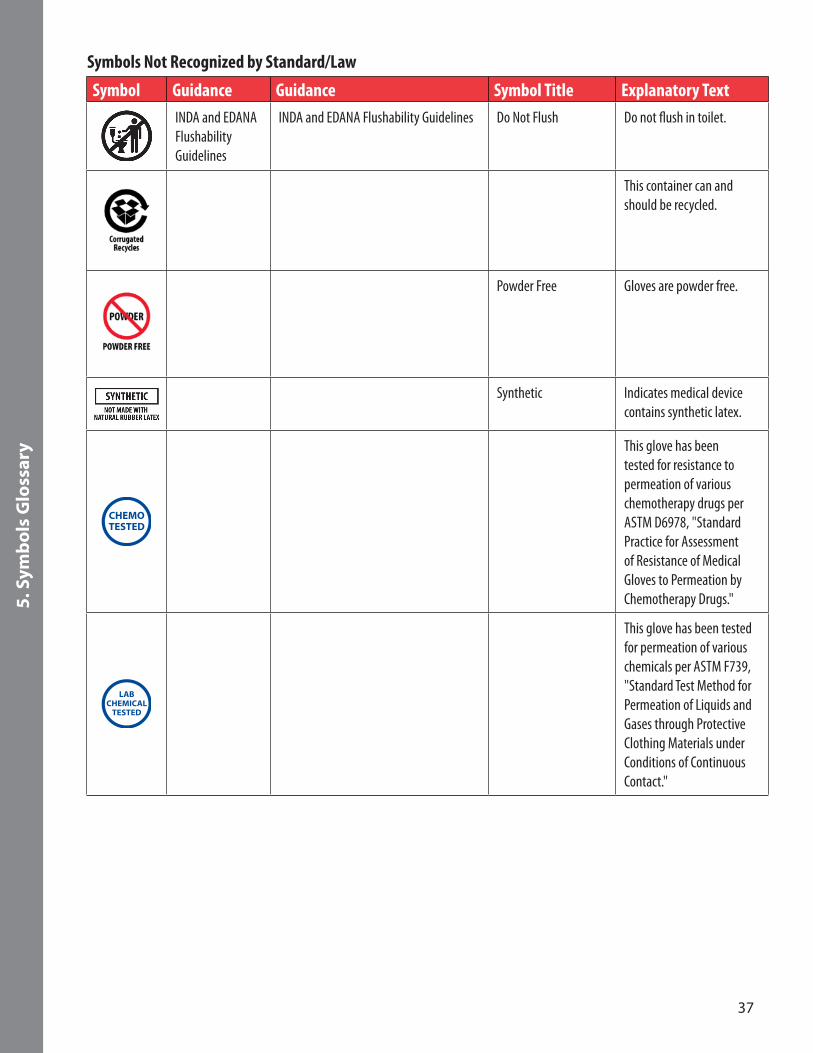
Symbols Not Recognized by Standard/Law
Symbol Guidance Guidance Symbol Title Explanatory TextINDA and EDANA Flushability Guidelines
INDA and EDANA Flushability Guidelines Do Not Flush Do not flush in toilet.
This container can and should be recycled.
Powder Free Gloves are powder free.
Synthetic Indicates medical device contains synthetic latex.
This glove has been tested for resistance to permeation of various chemotherapy drugs per ASTM D6978, "Standard Practice for Assessment of Resistance of Medical Gloves to Permeation by Chemotherapy Drugs."
This glove has been tested for permeation of various chemicals per ASTM F739, "Standard Test Method for Permeation of Liquids and Gases through Protective Clothing Materials under Conditions of Continuous Contact."
38
5. S
ymb
ols
Glo
ssar
y
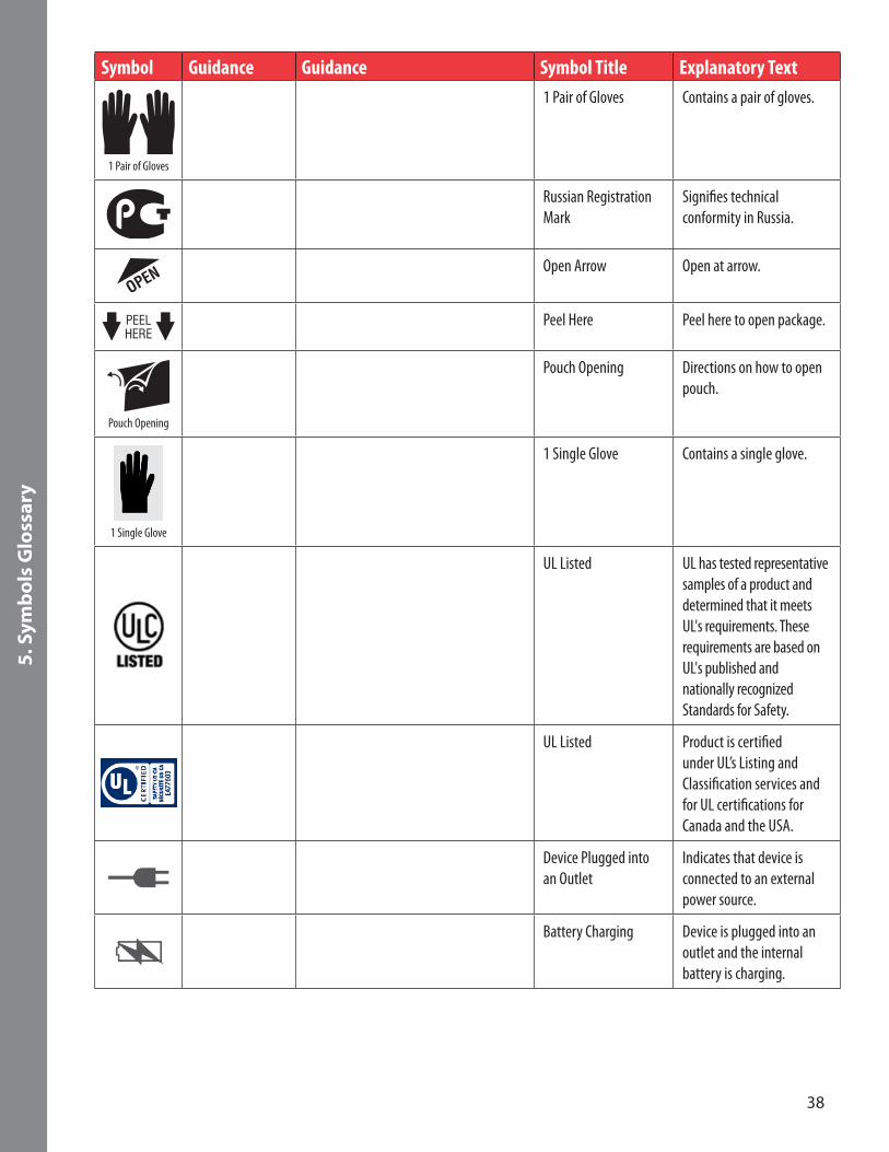
Symbol Guidance Guidance Symbol Title Explanatory Text
1 Pair of Gloves
1 Pair of Gloves Contains a pair of gloves.
Russian Registration Mark
Signifies technical conformity in Russia.
Open Arrow Open at arrow.
Peel Here Peel here to open package.
Pouch Opening
Pouch Opening Directions on how to open pouch.
1 Single Glove
1 Single Glove Contains a single glove.
UL Listed UL has tested representative samples of a product and determined that it meets UL's requirements. These requirements are based on UL's published and nationally recognized Standards for Safety.
UL Listed Product is certified under UL’s Listing and Classification services and for UL certifications for Canada and the USA.
Device Plugged into an Outlet
Indicates that device is connected to an external power source.
Battery Charging Device is plugged into an outlet and the internal battery is charging.
39
6. S
pec
ifica
tio
ns
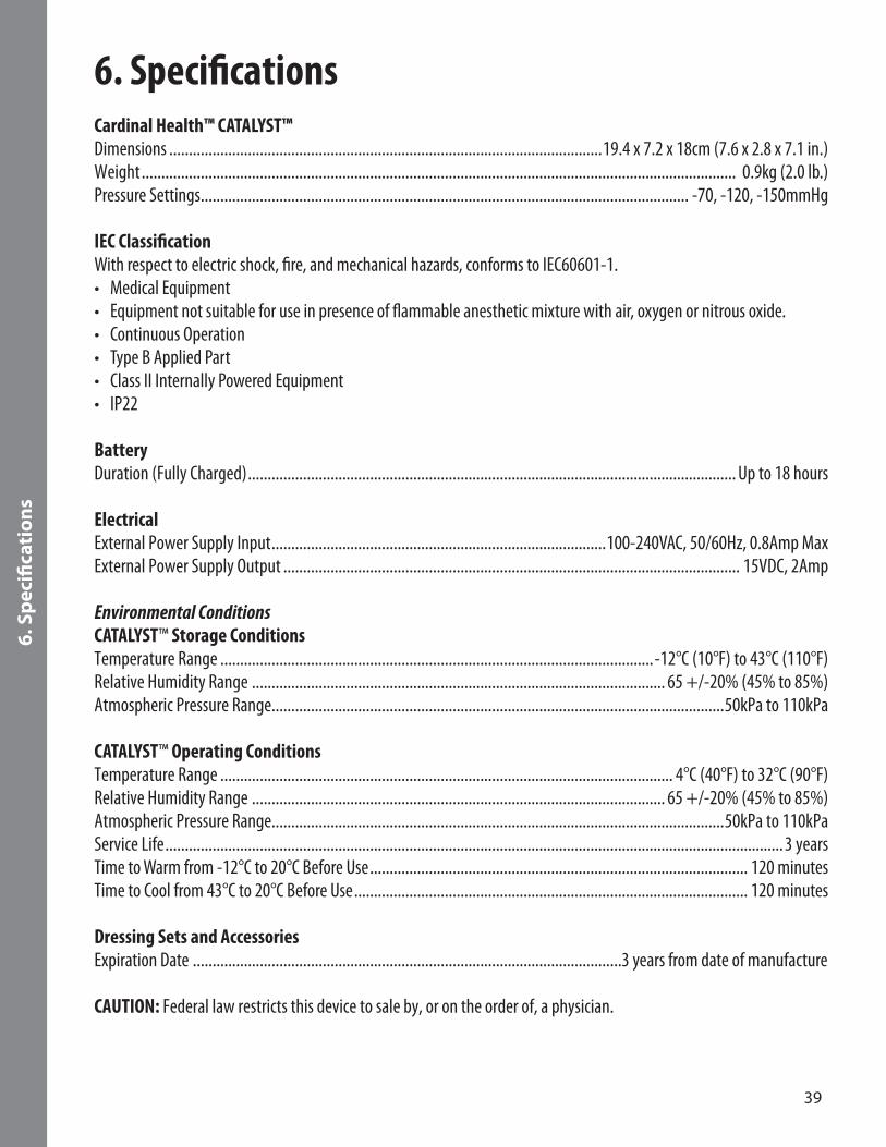
6. Specifications
Cardinal Health™ CATALYST™ Dimensions ..............................................................................................................19.4 x 7.2 x 18cm (7.6 x 2.8 x 7.1 in.)Weight ....................................................................................................................................................... 0.9kg (2.0 lb.)Pressure Settings ............................................................................................................................ -70, -120, -150mmHg
IEC Classification With respect to electric shock, fire, and mechanical hazards, conforms to IEC60601-1.• Medical Equipment• Equipment not suitable for use in presence of flammable anesthetic mixture with air, oxygen or nitrous oxide.• Continuous Operation• Type B Applied Part• Class II Internally Powered Equipment• IP22
Battery Duration (Fully Charged) ............................................................................................................................ Up to 18 hours
Electrical External Power Supply Input .....................................................................................100-240VAC, 50/60Hz, 0.8Amp MaxExternal Power Supply Output .................................................................................................................... 15VDC, 2Amp
Environmental Conditions CATALYST™ Storage Conditions Temperature Range ..............................................................................................................-12°C (10°F) to 43°C (110°F)Relative Humidity Range ......................................................................................................... 65 +/-20% (45% to 85%)Atmospheric Pressure Range...................................................................................................................50kPa to 110kPa
CATALYST™ Operating Conditions Temperature Range ................................................................................................................... 4°C (40°F) to 32°C (90°F) Relative Humidity Range ......................................................................................................... 65 +/-20% (45% to 85%)Atmospheric Pressure Range...................................................................................................................50kPa to 110kPa Service Life .............................................................................................................................................................3 years Time to Warm from -12°C to 20°C Before Use ................................................................................................ 120 minutesTime to Cool from 43°C to 20°C Before Use .................................................................................................... 120 minutes
Dressing Sets and AccessoriesExpiration Date .............................................................................................................3 years from date of manufacture
CAUTION: Federal law restricts this device to sale by, or on the order of, a physician.
40
6. S
pec
ifica
tio
ns
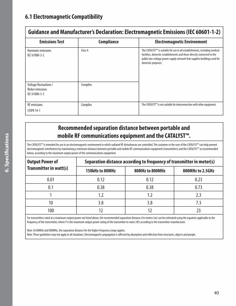
6.1 Electromagnetic Compatibility
Emissions Test
Harmonic emissionsIEC 61000-3-2
Guidance and Manufacturer’s Declaration: Electromagnetic Emissions (IEC 60601-1-2)
Class A
Complies
Complies
The CATALYST™ is suitable for use in all establishments, including medical facilities, domestic establishments and those directly connected to the public low-voltage power supply network that supplies buildings used for domestic purposes.
The CATALYST™ is not suitable for interconnection with other equipment.
Voltage fluctuations /flicker emissionsIEC 61000-3-3
RF emissions
CISPR 14-1
Compliance Electromagnetic Environment
Output Power of Transmitter in watt(s) 150kHz to 80MHz 80MHz to 800MHz 800MHz to 2.5GHz
Recommended separation distance between portable and mobile RF communications equipment and the CATALYST™.
Separation distance according to frequency of transmitter in meter(s)
0.010.11
10100
0.120.381.23.812
0.120.381.23.812
0.230.732.37.323
The CATALYST™ is intended for use in an electromagnetic environment in which radiated RF disturbances are controlled. The customer or the user of the CATALYST™ can help prevent electromagnetic interference by maintaining a minimum distance between portable and mobile RF communications equipment (transmitters) and the CATALYST™ as recommended below, according to the maximum output power of the communications equipment.
For transmitters rated at a maximum output power not listed above, the recommended separation distance d in meters (m) can be estimated using the equation applicable to the frequency of the transmitter, where P is the maximum output power rating of the transmitter in watts (W) according to the transmitter manufacturer.
Note: At 80MHz and 800MHz, the separation distance for the higher frequency range applies. Note: These guidelines may not apply in all situations. Electromagnetic propagation is affected by absorption and reflection from structures, objects and people.
41
6. S
pec
ifica
tio
ns
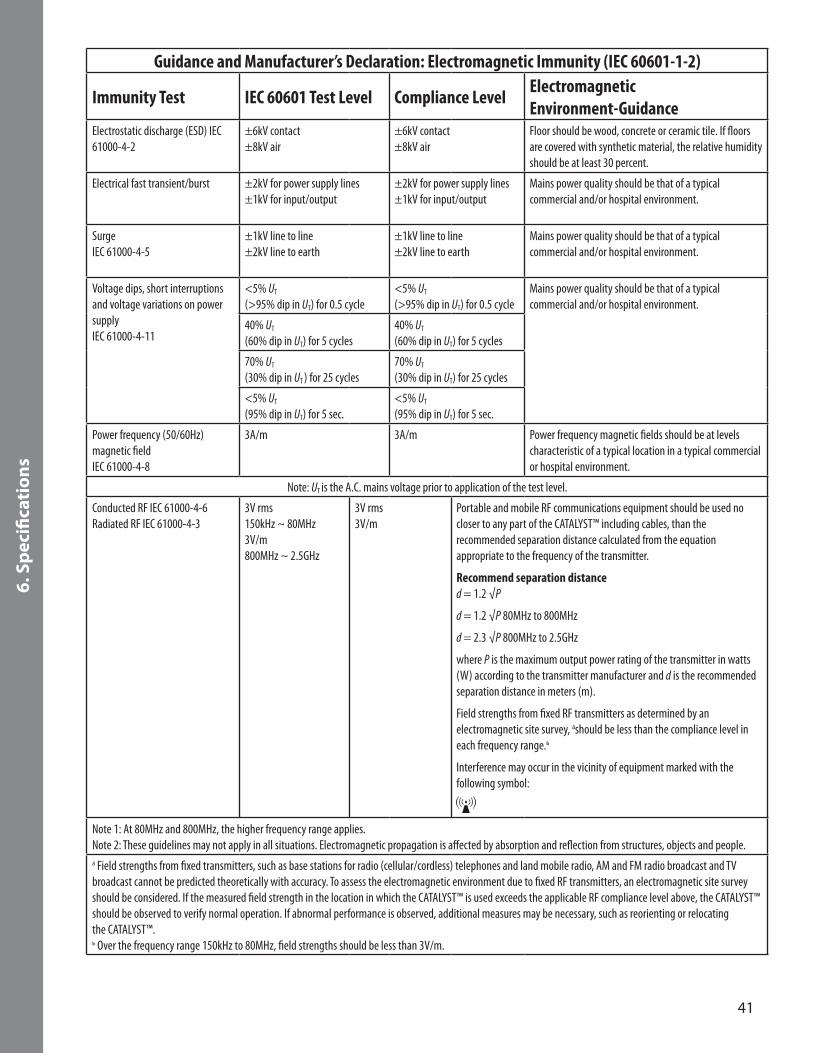
Guidance and Manufacturer’s Declaration: Electromagnetic Immunity (IEC 60601-1-2)
Immunity Test IEC 60601 Test Level Compliance Level Electromagnetic Environment-Guidance
Electrostatic discharge (ESD) IEC 61000-4-2
±6kV contact±8kV air
±6kV contact±8kV air
Floor should be wood, concrete or ceramic tile. If floors are covered with synthetic material, the relative humidity should be at least 30 percent.
Electrical fast transient/burst ±2kV for power supply lines±1kV for input/output
±2kV for power supply lines±1kV for input/output
Mains power quality should be that of a typical commercial and/or hospital environment.
SurgeIEC 61000-4-5
±1kV line to line±2kV line to earth
±1kV line to line±2kV line to earth
Mains power quality should be that of a typical commercial and/or hospital environment.
Voltage dips, short interruptions and voltage variations on power supply IEC 61000-4-11
<5% UT
(>95% dip in UT) for 0.5 cycle<5% UT
(>95% dip in UT) for 0.5 cycleMains power quality should be that of a typical commercial and/or hospital environment.
40% UT
(60% dip in UT) for 5 cycles40% UT
(60% dip in UT) for 5 cycles
70% UT
(30% dip in UT ) for 25 cycles70% UT
(30% dip in UT) for 25 cycles
<5% UT
(95% dip in UT) for 5 sec.<5% UT
(95% dip in UT) for 5 sec.
Power frequency (50/60Hz) magnetic field IEC 61000-4-8
3A/m 3A/m Power frequency magnetic fields should be at levels characteristic of a typical location in a typical commercial or hospital environment.
Note: UT is the A.C. mains voltage prior to application of the test level.
Conducted RF IEC 61000-4-6Radiated RF IEC 61000-4-3
3V rms150kHz ~ 80MHz3V/m800MHz ~ 2.5GHz
3V rms3V/m
Portable and mobile RF communications equipment should be used no closer to any part of the CATALYST™ including cables, than the recommended separation distance calculated from the equation appropriate to the frequency of the transmitter.
Recommend separation distance d = 1.2 √P
d = 1.2 √P 80MHz to 800MHz
d = 2.3 √P 800MHz to 2.5GHz
where P is the maximum output power rating of the transmitter in watts (W) according to the transmitter manufacturer and d is the recommended separation distance in meters (m).
Field strengths from fixed RF transmitters as determined by an electromagnetic site survey, ashould be less than the compliance level in each frequency range.ь
Interference may occur in the vicinity of equipment marked with the following symbol:
Note 1: At 80MHz and 800MHz, the higher frequency range applies.Note 2: These guidelines may not apply in all situations. Electromagnetic propagation is affected by absorption and reflection from structures, objects and people.a Field strengths from fixed transmitters, such as base stations for radio (cellular/cordless) telephones and land mobile radio, AM and FM radio broadcast and TV broadcast cannot be predicted theoretically with accuracy. To assess the electromagnetic environment due to fixed RF transmitters, an electromagnetic site survey should be considered. If the measured field strength in the location in which the CATALYST™ is used exceeds the applicable RF compliance level above, the CATALYST™ should be observed to verify normal operation. If abnormal performance is observed, additional measures may be necessary, such as reorienting or relocating the CATALYST™. ь Over the frequency range 150kHz to 80MHz, field strengths should be less than 3V/m.

42
7. A
dd
itio
nal
Par
ts
7. Additional Parts7.1 Replacement Product A.C. Power Adapter .............................................................................................................................................47-9000
7.2 Disposables and Accessories DressingsCardinal Health™ NPWT Occlusion Detection Small Foam Dressing Kit 10 x 8 x 3cm (10 per case) .....................48-1702Cardinal Health™ NPWT Occlusion Detection Medium Foam Dressing Kit 20 x 12.5 x 3cm (10 per case) ............48-1701Cardinal Health™ NPWT Occlusion Detection Large Foam Dressing Kit 25 x 15 x 3cm (10 per case) ...................48-1700Cardinal Health™ NPWT Occlusion Detection X-Large Foam Dressing Kit 58.5 x 33 x 3cm (10 per case) .............48-1703Cardinal Health™ NPWT Small White Foam Dressing 9.5 x 9.5 x 0.5cm (10 per case) ..........................................47-1751Cardinal Health™ NPWT Large White Foam Dressing 35 x 25 x 0.635cm (5 per case) ..........................................47-1755
CanistersCanister with Gel, 300cc (10 per case) .................................................................................................................48-4000Canister with Gel, 500cc (10 per case) .................................................................................................................48-4500
AccessoriesNPWT Irrigation Delivery Kit (5 per case) ........................................................................................................... 47-6500NPWT Irrigation Tubing with SpeedConnect™ (5 per case) ................................................................................. 47-6000NPWT Bridging Kit (5 per case) .......................................................................................................................... 47-1704CATALYST™ IV Pole Holder (1 per case) ............................................................................................................... 47-5500CATALYST™ Carrying Case (1 per case) ................................................................................................................ 47-9500NPWT Occlusion Detection Tubing with SpeedConnect™ (10 per case) .............................................................. 48-2000NPWT Occlusion Detection Y Connector (10 per case) ........................................................................................ 48-2500NPWT Polyurethane Drape (10 per case) ............................................................................................................ 47-7000NPWT SensiSkin™ Drape (10 per case) .............................................................................................................. 47-7100
NOTE: In order to assure the highest safety, quality and efficacy of the products, the Cardinal Health™ CATALYST™ should only be used with the Cardinal Health™ NPWT Occlusion Detection products listed above.

43
8. Q
ues
tio
ns
& In
form
atio
n
8. Questions & InformationFor questions, comments or additional information pertaining to the Cardinal Health™ CATALYST™, please contact your local Cardinal Health representative, or:
Call Customer Service at 1.866.484.6798
Cardinal HealthWaukegan, IL 60085www.cardinalhealth.com
Always consult a physician and product instructions for use prior to application.
CAUTION: Federal law restricts these devices to sale by, or on the order of, a physician.

Cardinal Health Waukegan, IL 60085 USA6803005 Rev. C 2019-11cardinalhealth.comREF 68-1132
© 2019 Cardinal Health. All Rights Reserved. CARDINAL HEALTH, the Cardinal Health LOGO, CATALYST, TWIST N’ CONNECT, SENSISKIN and SPEEDCONNECT are trademarks or registered trademarks of Cardinal Health and may be registered in the US and/or in other countries. Patent: cardinalhealth.com/patents