cardin elettronica spa via raffaello, 36 bl ... - adi.lv · instrucciones para el uso pag. 24 ......
TRANSCRIPT
1
ATTENTION! Before installing this device read the following instructions carefully!
Installation example Pag. 2Assembly Pag. 3-6Manual release drawings Pag. 6Fitting the holding brackets/electric lock Pag. 7-8Wiring diagrams (installation examples) Pag. 9-11Important remarks Pag. 15 User instructions Pag. 15Installation instructions Pag. 16Electrical connection Pag. 17Manual release mechanism Pag. 17Technical specifications Pag. 28
ATTENTION! Avant de commencer la pose, lire attentivement les instructions!
Exemple d’installation Pag. 2Montage Pag. 3-6Dessins du déverrouillage Pag. 6Fixation de la patte/serrure électrique Pag. 7-8Schéma électrique (exemple d’installation) Pag. 9-11Conseils importants Pag. 18Domaine d'application Pag. 18Instructions pour l’installation Pag. 19Branchement électrique Pag. 20Déverrouillage manuel Pag. 20Caractéristiques techniques Pag. 28
ACHTUNG! Bevor mit der Installation begonnen wird, sollte die Anleitung aufmerksam gelesen werden!
Anlagenart Seite 2Montagegearbeiten Seite 3-6Manuelle Entriegelungs Zeichenen Seite 6Anbringung Halterbügel/Elektroverriegelung Seite 7-8Elektrischer Schaltplan (Anlagenart) Seite 9-11Wichtige Hinweise Seite 21 Betriebsanleitung Seite 21Anleitungen zur Installation Seite 22 Elektrischer anschluss Seite 23Manuelle Entriegelung Seite 23Technische Daten Seite 28
AUTOMAZIONE PER CANCELLI A BATTENTEAUTOMATION FOR HINGED GATES
AUTOMATISME POUR PORTAILS BATTANTSDREHTORANTRIEBE
AUTOMATIZACION PARA CANCILLAS BATIENTES
ATTENZIONE! Prima di iniziare l'installazione leggere le istruzioni attentamente!
Esempio d'installazione Pag. 2Schema di montaggio Pag. 3-6Disegni di sblocco Pag. 6Fissaggio staffa/elettroserratura Pag. 7-8Schema elettrico (impianto tipo) Pag. 9-11Avvertenze importanti Pag. 12Istruzioni per l’uso Pag. 12Istruzione per l’installazione Pag. 13Collegamento elettrico Pag. 14Sblocco manuale Pag. 14Caratteristiche tecniche Pag. 28
¡ATENCIÓN! Antes de iniciar la instalación del sistema, leer atentamente las instrucciones.
Instalación estándar Pag. 2Esquema de montaje Pag. 3-6Dibujos del dispositivo de desbloqueo Pag. 6Fijación del soporte/electrocerradura Pag. 7-8Esquema eléctrico (instalación estándar) Pag. 9-11Advertencias importantes Pag. 24Instrucciones para el uso Pag. 24Instrucciones para la instalación Pag. 25Conexión eléctrica Pag. 26Desbloqueo manual Pag. 26Características técnicas Pag. 28
ZV
L240
.08-
Mod
:25/
06/2
007
ITALIANO
ENGLISH ESPAÑOL
DEUTSCH
FRANÇAIS
230Vac Motors 200/BL203200/BL203L200/BL203C200/BL203CE200/BL352200/BL452
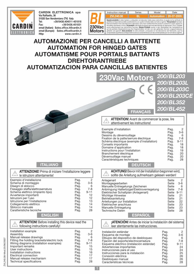
CARDIN ELETTRONICA spa Via Raffaello, 36 31020 San Vendemiano (TV) ItalyTel: +39/0438.404011-401818Fax: +39/0438.401831email (Italian): [email protected] (Europe): [email protected]: www.cardin.it
Questo prodotto è stato testato e collaudato nei laboratori della casa costruttrice, la quale ne ha verificato la perfetta corrispondenza delle caratteristiche con quelle richieste dalla normativa vigente. This product has been tried and tested in the manufacturer's laboratory who have verified that the product conforms in every aspect to the safety standards in force. Ce produit a été testé et essayé dans les laboratoires du fabriquant. Pour l'installer suivre attentivement les instructions fournies. Dieses Produkt wurde in den Werkstätten der Herstellerfirma auf die perfekte Übereinstimmung ihrer Eigenschaften mit den von den geltenden Normen vorgeschriebenen getestet und geprüft. Este producto ha sido probado y ensayado en los laboratorios del fabricante, que ha comprobado la perfecta correspondencia de sus características con las contempladas por la normativa vigente.
BL230VacMotors
Model DateInstruction manual Series
BL Automation 20-07-2005ZVL240.08
2
pro
do
tti Technocity (lam
p. fo
tocellule ecc.)
BL203
13-09-2006
DI0450
Descrip
tion :
Prod
uct Cod
e :
Date :
Draw
ing numb
er :
P.J.Heath
CA
RD
IN E
LET
TR
ON
ICA
S.p
.A - 31020 S
an Vendem
iano (T
V) Italy - via R
affaello, 36 Tel: 0438/401818 F
ax: 0438/401831
Draft :
All rights reserved
. Unauthorised
copying or use of the inform
ation contained in this d
ocument is p
unishable b
y law
INS
TALLA
ZIO
NE
TIP
O B
L203
1
4
58
11
10
76
9
230V-50Hz
2
13
3
12
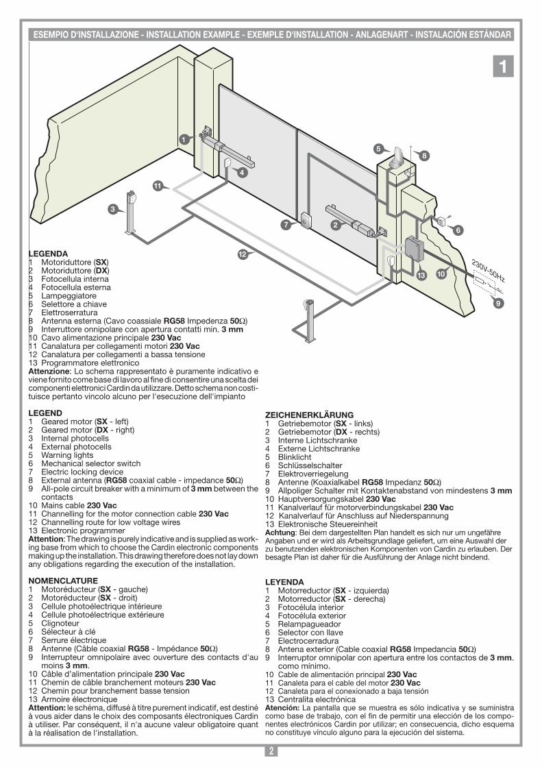
ESEMPIO D'INSTALLAZIONE - INSTALLATION ExAMPLE - ExEMPLE D'INSTALLATION - ANLAGENART - INSTALACIÓN ESTÁNDAR
1
LEGENDA1 Motoriduttore (Sx)2 Motoriduttore (Dx)3 Fotocellula interna 4 Fotocellula esterna5 Lampeggiatore 6 Selettore a chiave7 Elettroserratura8 Antenna esterna (Cavo coassiale RG58 Impedenza 50Ω) 9 Interruttore onnipolare con apertura contatti min. 3 mm10 Cavo alimentazione principale 230 Vac11 Canalatura per collegamenti motori 230 Vac12 Canalatura per collegamenti a bassa tensione13 Programmatore elettronico Attenzione: Lo schema rappresentato è puramente indicativo e viene fornito come base di lavoro al fine di consentire una scelta dei componenti elettronici Cardin da utilizzare. Detto schema non costi-tuisce pertanto vincolo alcuno per l'esecuzione dell'impianto
LEGEND1 Geared motor (Sx - left) 2 Geared motor (Dx - right) 3 Internal photocells 4 External photocells5 Warning lights6 Mechanical selector switch7 Electric locking device8 External antenna (RG58 coaxial cable - impedance 50Ω)9 All-pole circuit breaker with a minimum of 3 mm between the
contacts10 Mains cable 230 Vac11 Channelling for the motor connection cable 230 Vac12 Channelling route for low voltage wires13 Electronic programmerAttention: The drawing is purely indicative and is supplied as work-ing base from which to choose the Cardin electronic components making up the installation. This drawing therefore does not lay down any obligations regarding the execution of the installation.
NOMENCLATURE1 Motoréducteur (Sx - gauche)2 Motoréducteur (Sx - droit)3 Cellule photoélectrique intérieure 4 Cellule photoélectrique extérieure5 Clignoteur 6 Sélecteur à clé7 Serrure électrique 8 Antenne (Câble coaxial RG58 - Impédance 50Ω)9 Interrupteur omnipolaire avec ouverture des contacts d'au
moins 3 mm.10 Câble d’alimentation principale 230 Vac11 Chemin de câble branchement moteurs 230 Vac12 Chemin pour branchement basse tension13 Armoire électroniqueAttention: le schéma, diffusé à titre purement indicatif, est destiné à vous aider dans le choix des composants électroniques Cardin à utiliser. Par conséquent, il n'a aucune valeur obligatoire quant à la réalisation de l'installation.
ZEICHENERkLäRUNG1 Getriebemotor (Sx - links)2 Getriebemotor (Dx - rechts)3 Interne Lichtschranke 4 Externe Lichtschranke 5 Blinklicht6 Schlüsselschalter7 Elektroverriegelung 8 Antenne (Koaxialkabel RG58 Impedanz 50Ω)9 Allpoliger Schalter mit Kontaktenabstand von mindestens 3 mm10 Hauptversorgungskabel 230 Vac11 Kanalverlauf für motorverbindungskabel 230 Vac12 Kanalverlauf für Anschluss auf Niederspannung13 Elektronische SteuereinheitAchtung: Bei dem dargestellten Plan handelt es sich nur um ungefähre Angaben und er wird als Arbeitsgrundlage geliefert, um eine Auswahl der zu benutzenden elektronischen Komponenten von Cardin zu erlauben. Der besagte Plan ist daher für die Ausführung der Anlage nicht bindend.
LEYENDA1 Motorreductor (Sx - izquierda)2 Motorreductor (Sx - derecha)3 Fotocélula interior 4 Fotocélula exterior5 Relampagueador6 Selector con llave7 Electrocerradura 8 Antena exterior (Cable coaxial RG58 Impedancia 50Ω)9 Interruptor omnipolar con apertura entre los contactos de 3 mm.
como mínimo.10 Cable de alimentación principal 230 Vac11 Canaleta para el cable del motor 230 Vac 12 Canaleta para el conexionado a baja tensión13 Centralita electrónicaAtención: La pantalla que se muestra es sólo indicativa y se suministra como base de trabajo, con el fin de permitir una elección de los compo-nentes electrónicos Cardin por utilizar; en consecuencia, dicho esquema no constituye vínculo alguno para la ejecución del sistema.
3
SCALA: 1:2
Prodotti Technocity (sblocco nuovo)
BL202/L
07-07-2003
DI0290 Description :
Product Code :
Date:
Drawing number :
P.J.Heath
CARDIN ELETTRONICA S.p.A - 31020 San Vendemiano (TV) Italy - via Raffaello, 36 Tel: 0438/401818 Fax: 0438/401831
Draft :
All rights reserved. Unauthorised copying or use of the information contained in this document is punishable by law
SCHEMA DI MONTAGGIO BL202/L
1 2
34
5
7
8
6
9
10
2
Nota - Note - Hinweis - Remarque - Nota
SCALA: 1:2
Prodotti Technocity (Sblocco nuovo)
BL202C
07-07-2003
DI0291 Description :
Product Code :
Date :
Drawing number :
P.J.Heath
CARDIN ELETTRONICA S.p.A - 31020 San Vendemiano (TV) Italy - via Raffaello, 36 Tel: 0438/401818 Fax: 0438/401831
Draft :
All rights reserved. Unauthorised copying or use of the information contained in this document is punishable by law
SCHEMA DI MONTAGGIO BL202C
1
2
5
6
9
3
7
10
8
12
4
11
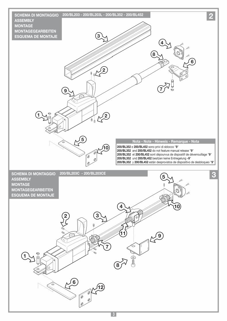
SCHEMA DI MONTAGGIOASSEMBLY MONTAGE MONTAGEGEARBEITENESQUEMA DE MONTAJE
200/BL203 - 200/BL203L - 200/BL352 - 200/BL452
200/BL352 e 200/BL452 sono privi di sblocco "9" 200/BL352 and 200/BL452 do not feature manual release "9"200/BL352 et 200/BL452 sont dépourvus de dispositif de déverrouillage "9"200/BL352 und 200/BL452 besitzen keine Entriegelung «9"200/BL352 y 200/BL452 están desprovistos de dispositivo de desbloqueo "9"
2
SCHEMA DI MONTAGGIOASSEMBLY MONTAGE MONTAGEGEARBEITENESQUEMA DE MONTAJE
200/BL203C - 200/BL203CE 3
4
SCALA: 1:2
Prodotti Technocity
BL203C-BL2124C
01-10-2003
DI0315 Description :
Product Code :
Date :
Drawing number :
P.J.Heath
CARDIN ELETTRONICA S.p.A - 31020 San Vendemiano (TV) Italy - via Raffaello, 36 Tel: 0438/401818 Fax: 0438/401831
Draft :
All rights reserved. Unauthorised copying or use of the information contained in this document is punishable by law
Vista pistone
832
384
8112
120
80
743
80
90C
SCALA: 1:2
Prodotti Technocity
BL203-BL2124
01-10-2003
DI0313 Description :
Product Code :
Date :
Drawing number :
P.J.Heath
CARDIN ELETTRONICA S.p.A - 31020 San Vendemiano (TV) Italy - via Raffaello, 36 Tel: 0438/401818 Fax: 0438/401831
Draft :
All rights reserved. Unauthorised copying or use of the information contained in this document is punishable by law
Vista pistone
1076
80120
725
1000
80
12 5990
A
SCALA: 1:2
Prodotti Technocity
BL203L -BL2124L
01-10-2003
DI0314 Description :
Product Code :
Date :
Drawing number :
P.J.Heath
CARDIN ELETTRONICA S.p.A - 31020 San Vendemiano (TV) Italy - via Raffaello, 36 Tel: 0438/401818 Fax: 0438/401831
Draft :
All rights reserved. Unauthorised copying or use of the information contained in this document is punishable by law
Vista pistone
1416
80120
900
1350
80
12 5490
B
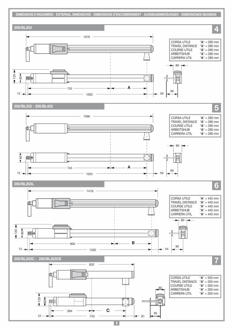
DIMENSIONI D'INGOMBRO - ExTERNAL DIMENSIONS - DIMENSIONS D'ENCOMBREMENT - AUSSENABMESSUNGEN - DIMENSIONES MAxIMAS
SCALA: 1:2
Prodotti Technocity
BL352
16-11-98
DI0101 Description :
Product Code :
Date :
Drawing number :
P.J.Heath
CARDIN ELETTRONICA S.p.A - 31020 San Vendemiano (TV) Italy - via Raffaello, 36 Tel: 0438/401818 Fax: 0438/401831
Draft :
All rights reserved. Unauthorised copying or use of the information contained in this document is punishable by law
Vista pistone 352
1096
80
745
1025
80
12 5990
A
CORSA UTILE "A" = 280 mmTRAVEL DISTANCE "A" = 280 mmCOURSE UTILE "A" = 280 mm ARBEITSHUB "A" = 280 mmCARRERA UTIL "A" = 280 mm
200/BL203 4
200/BL352 - 200/BL452 5
200/BL203L 6
200/BL203C - 200/BL203CE 7
CORSA UTILE "A" = 280 mmTRAVEL DISTANCE "A" = 280 mmCOURSE UTILE "A" = 280 mm ARBEITSHUB "A" = 280 mmCARRERA UTIL "A" = 280 mm
CORSA UTILE "A" = 445 mmTRAVEL DISTANCE "A" = 445 mmCOURSE UTILE "A" = 445 mm ARBEITSHUB "A" = 445 mmCARRERA UTIL "A" = 445 mm
CORSA UTILE "A" = 350 mmTRAVEL DISTANCE "A" = 350 mmCOURSE UTILE "A" = 350 mm ARBEITSHUB "A" = 350 mmCARRERA UTIL "A" = 350 mm
5
SCALA: 1:2
Prodotti Technocity
BL202C
01-02-99
DI0123 Description :
Product Code :
Date :
Drawing number :
P.J.Heath
CARDIN ELETTRONICA S.p.A - 31020 San Vendemiano (TV) Italy - via Raffaello, 36 Tel: 0438/401818 Fax: 0438/401831
Draft :
All rights reserved. Unauthorised copying or use of the information contained in this document is punishable by law
limite d'impiego
α
743 max.
D
x
2
A
C
1
B
389
min
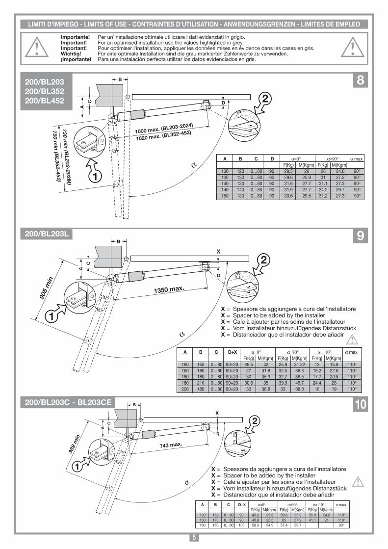
A B C D+x α=0° α=90° α=110° α max F(Kg) M(Kgm) F(Kg) M(Kgm) F(Kg) M(Kgm) 130 160 0…80 90 43.2 25.6 59.6 35.3 35.8 24.8 110° 130 170 0…80 90 43.8 25.5 65 37.9 41.1 24 110° 180 160 0…80 105 58.3 34.9 57.4 33.7 90°
LIMITI D’IMPIEGO - LIMITS OF USE - CONTRAINTES D'UTILISATION - ANWENDUNGSGRENZEN - LIMITES DE EMPLEO
A
SCALA: 1:2
Prodotti Technocity
BL202
21-10-98
DI0121 Description :
Product Code :
Date :
Drawing number :
P.J.Heath
CARDIN ELETTRONICA S.p.A - 31020 San Vendemiano (TV) Italy - via Raffaello, 36 Tel: 0438/401818 Fax: 0438/401831
Draft :
All rights reserved. Unauthorised copying or use of the information contained in this document is punishable by law
limite d'impiego
B
C D
α
1000 max. (BL203-2024)
A B C D α=0° α=90° α max F(Kg) M(Kgm) F(Kg) M(Kgm) 130 120 0…80 90 29,3 26 28 24.8 90° 130 130 0…80 90 29.6 25.9 31 27.2 90° 140 120 0…80 90 31.6 27.7 31.1 27.3 90° 140 140 0…80 90 31.9 27.7 34.2 29.7 90° 150 130 0…80 90 33.6 29.5 31.2 27.3 90°
1
2
1020 max. (BL352-452)
750 min
(BL
352-452)730 m
in (B
L202-202M
)
SCALA: 1:2
Prodotti Technocity
BL202L
29-01-99
DI0122 Description :
Product Code :
Date :
Drawing number :
P.J.Heath
CARDIN ELETTRONICA S.p.A - 31020 San Vendemiano (TV) Italy - via Raffaello, 36 Tel: 0438/401818 Fax: 0438/401831
Draft :
All rights reserved. Unauthorised copying or use of the information contained in this document is punishable by law
limite d'impiego
D
α
1350 max.
x
2
A
C
1
B
905
min
A B C D+x α=0° α=90° α=110° α max F(Kg) M(Kgm) F(Kg) M(Kgm) F(Kg) M(Kgm) 160 150 0…80 90+20 26,5 32 25.9 31.22 13 15.8 110° 160 180 0…80 90+20 27 31.8 32.5 38.3 19.2 22.6 110° 180 180 0…80 90+20 30 35.3 32.7 38.5 17.7 20.8 110° 180 210 0…80 90+20 30,6 35 39.9 45.7 24.4 28 110° 200 180 0…80 90+20 33 38.8 33 38.8 16 19 110°
x = Spessore da aggiungere a cura dell'installatorex = Spacer to be added by the installerx = Cale à ajouter par les soins de l'installateurx = Vom Installateur hinzuzufügendes Distanzstückx = Distanciador que el instalador debe añadir
x = Spessore da aggiungere a cura dell'installatorex = Spacer to be added by the installerx = Cale à ajouter par les soins de l'installateurx = Vom Installateur hinzuzufügendes Distanzstückx = Distanciador que el instalador debe añadir
Importante! Per un’installazione ottimale utilizzare i dati evidenziati in grigio. Important! For an optimised installation use the values highlighted in grey.Important! Pour optimiser l'installation, appliquer les données mises en évidence dans les cases en gris.Wichtig! Für eine optimale Installation sind die grau markierten Zahlenwerte zu verwenden.¡Importante! Para una instalación perfecta utilizar los datos evidenciados en gris.
200/BL203200/BL352200/BL452
8
200/BL203L 9
200/BL203C - BL203CE 10
6
SBLOCCO MANUALE - MANUAL RELEASE - DÉVERROUILLAGE MANUEL - MANUELLE ENTRIEGELUNG - DESBLOQUEO MANUAL
ESEMPIO D’INSTALLAZIONE-INSTALLATION ExAMPLE-ExEMPLE D'INSTALLATION-INSTALLATIONSART-EJEMPLO DE INSTALACIÓN
SCALA: 1: Prodotti Technocity
BL202 (serie)
30-07-98
DI0091 Description :
Product Code :
Date :
Drawing number :
P.J.Heath
CARDIN ELETTRONICA S.p.A - 31020 San Vendemiano (TV) Italy - via Raffaello, 36 Tel: 0438/401818 Fax: 0438/401831
Draft :
All rights reserved. Unauthorised copying or use of the information contained in this document is punishable by law
Installazione tipo
α
2
1
3
11
12
Sblocco motore fig.1
02.07.03
DM0721 Description :
Product Code :
Date :
Drawing number :
P.J.Heath
CARDIN ELETTRONICA S.p.A - 31020 San Vendemiano (TV) Italy - via Raffaello, 36 Tel: 0438/401818 Fax: 0438/401831
Draft :
All rights reserved. Unauthorised copying or use of the information contained in this document is punishable by law
BL202 SBLOCCO BL
Sblocco motore fig.2
02.07.03
DM0722 Description :
Product Code :
Date :
Drawing number :
P.J.Heath
CARDIN ELETTRONICA S.p.A - 31020 San Vendemiano (TV) Italy - via Raffaello, 36 Tel: 0438/401818 Fax: 0438/401831
Draft :
All rights reserved. Unauthorised copying or use of the information contained in this document is punishable by law
BL202 SBLOCCO BL
Sblocco motore fig.3
02.07.03
DM0723 Description :
Product Code :
Date :
Drawing number :
P.J.Heath
CARDIN ELETTRONICA S.p.A - 31020 San Vendemiano (TV) Italy - via Raffaello, 36 Tel: 0438/401818 Fax: 0438/401831
Draft :
All rights reserved. Unauthorised copying or use of the information contained in this document is punishable by law
BL202 SBLOCCO BL
Sblocco motore fig.4
02.07.03
DM0724 Description :
Product Code :
Date :
Drawing number :
P.J.Heath
CARDIN ELETTRONICA S.p.A - 31020 San Vendemiano (TV) Italy - via Raffaello, 36 Tel: 0438/401818 Fax: 0438/401831
Draft :
All rights reserved. Unauthorised copying or use of the information contained in this document is punishable by law
BL202 SBLOCCO BL
A B
D E
Sblocco motore fig.3
02.07.03
DM0726 Description :
Product Code :
Date :
Drawing number :
P.J.Heath
CARDIN ELETTRONICA S.p.A - 31020 San Vendemiano (TV) Italy - via Raffaello, 36 Tel: 0438/401818 Fax: 0438/401831
Draft :
All rights reserved. Unauthorised copying or use of the information contained in this document is punishable by law
BL202 SBLOCCO BL
C
7
SCALA: 1:2
Prodotti Technocity
BL202 (SERIE)
29-07-98
DI0082 Description :
Product Code :
Date :
Drawing number :
P.J.Heath
CARDIN ELETTRONICA S.p.A - 31020 San Vendemiano (TV) Italy - via Raffaello, 36 Tel: 0438/401818 Fax: 0438/401831
Draft :
All rights reserved. Unauthorised copying or use of the information contained in this document is punishable by law
Staffa attacco pilastro
SCALA: 1:2
Prodotti Technocity
BL202 (SERIE)
29-07-98
DI0083 Description :
Product Code :
Date :
Drawing number :
P.J.Heath
CARDIN ELETTRONICA S.p.A - 31020 San Vendemiano (TV) Italy - via Raffaello, 36 Tel: 0438/401818 Fax: 0438/401831
Draft :
All rights reserved. Unauthorised copying or use of the information contained in this document is punishable by law
Staffa attacco cancello BL202/L
SCALA: 1:2
Prodotti Technocity
BL202 (SERIE)
29-07-98
DI0084 Description :
Product Code :
Date :
Drawing number :
P.J.Heath
CARDIN ELETTRONICA S.p.A - 31020 San Vendemiano (TV) Italy - via Raffaello, 36 Tel: 0438/401818 Fax: 0438/401831
Draft :
All rights reserved. Unauthorised copying or use of the information contained in this document is punishable by law
Staffa attacco cancello BL202C
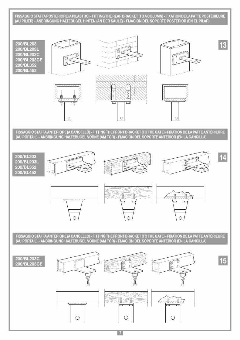
FISSAGGIO STAFFA POSTERIORE (A PILASTRO) - FITTING THE REAR BRACkET (TO A COLUMN) - FIxATION DE LA PATTE POSTÉRIEURE (AU PILIER) - ANBRINGUNG HALTEBüGEL HINTEN (AN DER SäULE) - FIJACIÓN DEL SOPORTE POSTERIOR (EN EL PILAR)
FISSAGGIO STAFFA ANTERIORE (A CANCELLO) - FITTING THE FRONT BRACkET (TO THE GATE) - FIxATION DE LA PATTE ANTÉRIEURE (AU PORTAIL) - ANBRINGUNG HALTEBüGEL VORNE (AM TOR) - FIJACIÓN DEL SOPORTE ANTERIOR (EN LA CANCILLA)
FISSAGGIO STAFFA ANTERIORE (A CANCELLO) - FITTING THE FRONT BRACkET (TO THE GATE) - FIxATION DE LA PATTE ANTÉRIEURE (AU PORTAIL) - ANBRINGUNG HALTEBüGEL VORNE (AM TOR) - FIJACIÓN DEL SOPORTE ANTERIOR (EN LA CANCILLA)
200/BL203200/BL203L200/BL203C200/BL203CE200/BL352200/BL452
13
200/BL203200/BL203L200/BL352200/BL452
14
200/BL203C200/BL203CE 15
8
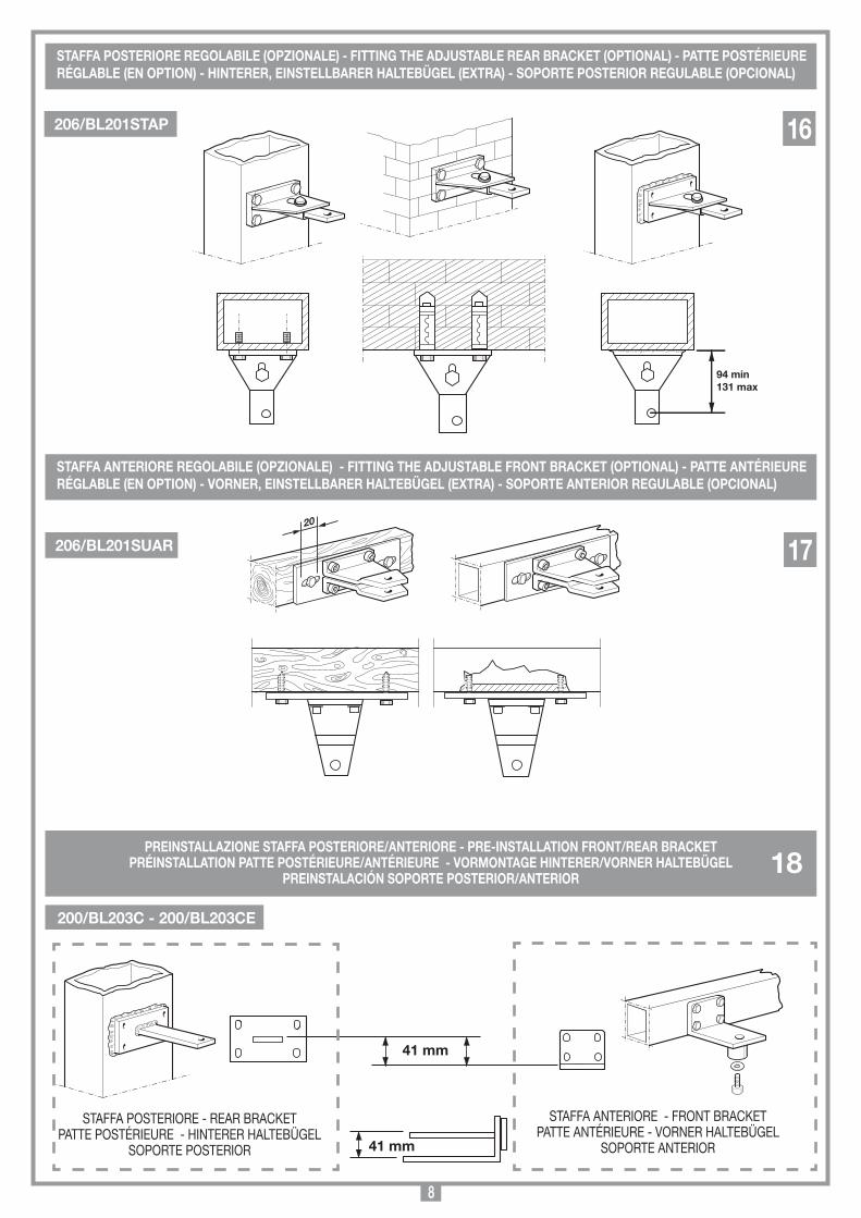
STAFFA POSTERIORE REGOLABILE (OPZIONALE) - FITTING THE ADJUSTABLE REAR BRACkET (OPTIONAL) - PATTE POSTÉRIEURE RÉGLABLE (EN OPTION) - HINTERER, EINSTELLBARER HALTEBüGEL (ExTRA) - SOPORTE POSTERIOR REGULABLE (OPCIONAL)
STAFFA ANTERIORE REGOLABILE (OPZIONALE) - FITTING THE ADJUSTABLE FRONT BRACkET (OPTIONAL) - PATTE ANTÉRIEURE RÉGLABLE (EN OPTION) - VORNER, EINSTELLBARER HALTEBüGEL (ExTRA) - SOPORTE ANTERIOR REGULABLE (OPCIONAL)
SCALA: 1:2
Prodotti Technocity
BL202 (SERIE)
07-10-98
DI0095 Description :
Product Code :
Date :
Drawing number :
P.J.Heath
CARDIN ELETTRONICA S.p.A - 31020 San Vendemiano (TV) Italy - via Raffaello, 36 Tel: 0438/401818 Fax: 0438/401831
Draft :
All rights reserved. Unauthorised copying or use of the information contained in this document is punishable by law
Staffa attacco pilastro regolabile
94 min131 max
SCALA: 1:2
Prodotti Technocity
BL202 (SERIE)
12-10-98
DI0096 Description :
Product Code :
Date :
Drawing number :
P.J.Heath
CARDIN ELETTRONICA S.p.A - 31020 San Vendemiano (TV) Italy - via Raffaello, 36 Tel: 0438/401818 Fax: 0438/401831
Draft :
All rights reserved. Unauthorised copying or use of the information contained in this document is punishable by law
Staffa attacco cancello regolabile
20
206/BL201STAP 16
206/BL201SUAR 17
41 mm
41 mm
Descrip
tion :
Prod
uct Cod
e :
Date :
Draw
ing numb
er :
P.J.Heath
CA
RD
IN E
LE
TT
RO
NIC
A S
.p.A
- 31020 San Vend
emiano
(TV
) Italy - via Raffaello
, 36 Tel: 0438/401818 Fax: 0438/401831
Draft :
All rights reserved
. Unauthorised
copying or use of the inform
ation contained in this d
ocument is p
unishable b
y law
Installazione sq
uadretta p
osterio
re 41 mm
BL
29-10-2006
DI0461
STAFFA POSTERIORE - REAR BRACKETPATTE POSTéRIEURE - HINTERER HALTEBÜGEL
SOPORTE POSTERIOR
PREINSTALLAZIONE STAFFA POSTERIORE/ANTERIORE - PRE-INSTALLATION FRONT/REAR BRACkETPRÉINSTALLATION PATTE POSTÉRIEURE/ANTÉRIEURE - VORMONTAGE HINTERER/VORNER HALTEBüGEL
PREINSTALACIÓN SOPORTE POSTERIOR/ANTERIOR
STAFFA ANTERIORE - FRONT BRACKETPATTE ANTéRIEURE - VORNER HALTEBÜGEL
SOPORTE ANTERIOR
18
200/BL203C - 200/BL203CE
9
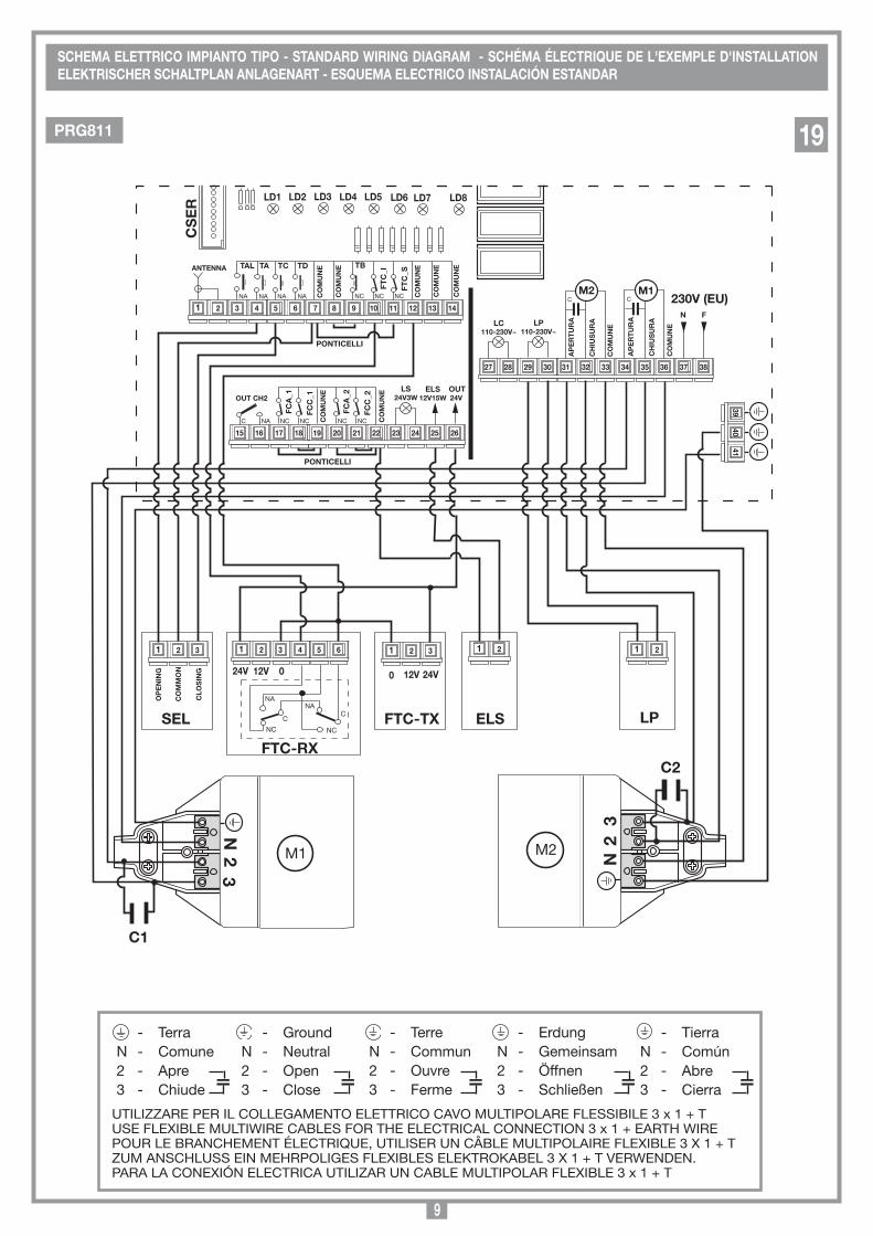
SCHEMA ELETTRICO IMPIANTO TIPO - STANDARD WIRING DIAGRAM - SCHÉMA ÉLECTRIQUE DE L'ExEMPLE D'INSTALLATION ELEkTRISCHER SCHALTPLAN ANLAGENART - ESQUEMA ELECTRICO INSTALACIÓN ESTANDAR
- TerraN - Comune2 - Apre3 - Chiude
- GroundN - Neutral2 - Open3 - Close
- TerreN - Commun2 - Ouvre3 - Ferme
- ErdungN - Gemeinsam2 - Öffnen3 - Schließen
- TierraN - Común2 - Abre3 - Cierra
Programmatore a microcontrollore per 2 motori
BL
28-03-2004
DI00333 Description :
Product Code :
Date :
Drawing number :
P.J.Heath
CARDIN ELETTRONICA S.p.A - 31020 San Vendemiano (TV) Italy - via Raffaello, 36 Tel: 0438/401818 Fax: 0438/401831
Draft :
All rights reserved. Unauthorised copying or use of the information contained in this document is punishable by law
COLLEGAMENTO SERIE BL203
C
LD1 LD2 LD3 LD4 LD6 LD7 LD5 LD8
TAL
CS
ER
26 25 24 23 22 21 20 19 18 17 16 15
38 37 36 35 34 33 32 31 30 29 28 27
TA ANTENNA TC TD
FTC
_S
FTC
_I
NC NC NC
TB
CO
MU
NE
CO
MU
NE
CO
MU
NE
CO
MU
NE
CO
MU
NE
1 14 13 12 11 10 9 8 7 6 5 4 3 2 FC
C_1
FCA
_1
NC NC CO
MU
NE
FCC
_2
FCA
_2
NC NC CO
MU
NE
NA C
OUT CH2 LS
24V3W ELS
12V15W OUT 24V
NA NA NA NA
LC 110-230V~
LP 110-230V~
M2
CH
IUS
UR
A
CO
MU
NE
AP
ER
TU
RA
C M1
CH
IUS
UR
A
CO
MU
NE
AP
ER
TU
RA
N F
41 40
39
SEL
24V
PONTICELLI
12V 0
C
1 6 5 4 3 2
NA
NC NC
C NA
FTC-Rx
1 3 2
CLO
SIN
G
CO
MM
ON
OP
EN
ING
1 3 2
24V 12V 0
FTC-Tx
N 2 3
M1 N 2
3
M2
PONTICELLI
1 2
C1
1 2
ELS LP
230V (EU)
C2
UTILIZZARE PER IL COLLEGAMENTO ELETTRICO CAVO MULTIPOLARE FLESSIBILE 3 x 1 + TUSE FLEXIBLE MULTIWIRE CABLES FOR THE ELECTRICAL CONNECTION 3 x 1 + EARTH WIREPOUR LE BRANCHEMENT éLECTRIQUE, UTILISER UN CÂBLE MULTIPOLAIRE FLEXIBLE 3 X 1 + TZUM ANSCHLUSS EIN MEHRPOLIGES FLEXIBLES ELEKTROKABEL 3 X 1 + T VERWENDEN.PARA LA CONEXIÓN ELECTRICA UTILIZAR UN CABLE MULTIPOLAR FLEXIBLE 3 x 1 + T
PRG811 19
10
11 12
C
TAL
Programmatore (PRG101LSOCE) per 1-2 motori
Serie BL203
04-03-2004
DI0134 Description :
Product Code :
Date :
Drawing number :
P.J.Heath
CARDIN ELETTRONICA S.p.A - 31020 San Vendemiano (TV) Italy - via Raffaello, 36 Tel: 0438/401818 Fax: 0438/401831
Draft :
All rights reserved. Unauthorised copying or use of the information contained in this document is punishable by law
COLLEGAMENTO SERIE BL230 (110V - 230V)
23 22 21 20 19 18 17 16 15 14 13
10 9 8 7 6 5
TD
ANTENNA
TC TA
NC
TB
CO
MM
ON
FCA
FCC
C
OM
MO
N
NO NO NO NO
M2
CLO
SIN
G
CO
MM
ON
OP
EN
ING
C M1
OP
EN
ING
CO
MM
ON
CLO
SIN
G
4 3
2
24V 12V 0
C
1 6 5 4 3 2
NO
NC NC
C NO
1 3 2
CLO
SIN
G
CO
MM
ON
OP
EN
ING
1 3 2
24V 12V 0
N 2
3
M1
N 2
3
M2
BRIDGE
1 2
C2
1 2
CLO
SIN
G M
2
OP
EN
ING
M2
CLO
SIN
G M
1
OP
EN
ING
M1
CO
MM
ON
TOR
QU
E L
IMIT
Max: 230 Vac A: 195 Vac B: 170 Vac C: 145 Vac MIN: 120 Vac
MAX A B C MIN
CO
MM
ON
24V
AC
ELS
12V
~
24 25 26 27 28 29 30 31 32
NC NC
FTC
_S
NC
FTC
_I
NC
LS LP
24V
Neutral
Live
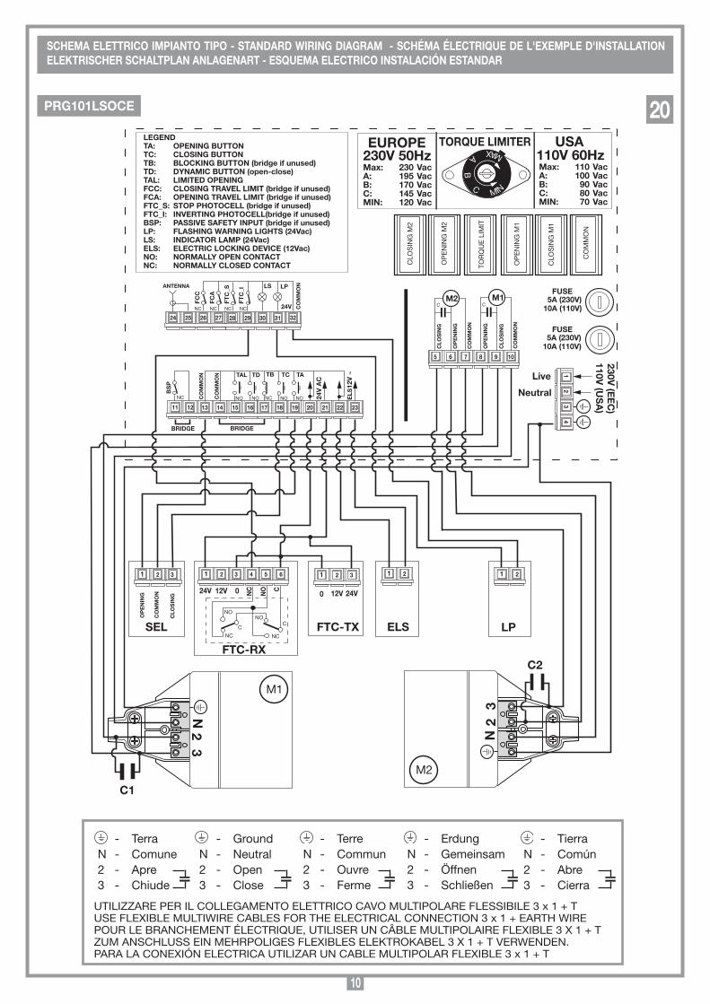
LEGEND TA: OPENING BUTTON TC: CLOSING BUTTON TB: BLOCkING BUTTON (bridge if unused) TD: DYNAMIC BUTTON (open-close) TAL: LIMITED OPENING FCC: CLOSING TRAVEL LIMIT (bridge if unused) FCA: OPENING TRAVEL LIMIT (bridge if unused) FTC_S: STOP PHOTOCELL (bridge if unused) FTC_I: INVERTING PHOTOCELL(bridge if unused) BSP: PASSIVE SAFETY INPUT (bridge if unused) LP: FLASHING WARNING LIGHTS (24Vac) LS: INDICATOR LAMP (24Vac) ELS: ELECTRIC LOCkING DEVICE (12Vac) NO: NORMALLY OPEN CONTACT NC: NORMALLY CLOSED CONTACT
C
NO
NC
1
BRIDGE
BS
P
NC
FUSE 5A (230V)
10A (110V)
C1
TORQUE LIMITER
Max: 110 Vac A: 100 Vac B: 90 Vac C: 80 Vac MIN: 70 Vac
230V 50Hz 110V 60Hz
FUSE 5A (230V)
10A (110V)
230V (E
EC
) 110V
(US
A)
EUROPE USA
SEL
FTC-Rx
FTC-Tx ELS LP
- TerraN - Comune2 - Apre3 - Chiude
- GroundN - Neutral2 - Open3 - Close
- TerreN - Commun2 - Ouvre3 - Ferme
- ErdungN - Gemeinsam2 - Öffnen3 - Schließen
- TierraN - Común2 - Abre3 - Cierra UTILIZZARE PER IL COLLEGAMENTO ELETTRICO CAVO MULTIPOLARE FLESSIBILE 3 x 1 + T
USE FLEXIBLE MULTIWIRE CABLES FOR THE ELECTRICAL CONNECTION 3 x 1 + EARTH WIREPOUR LE BRANCHEMENT éLECTRIQUE, UTILISER UN CÂBLE MULTIPOLAIRE FLEXIBLE 3 X 1 + TZUM ANSCHLUSS EIN MEHRPOLIGES FLEXIBLES ELEKTROKABEL 3 X 1 + T VERWENDEN.PARA LA CONEXIÓN ELECTRICA UTILIZAR UN CABLE MULTIPOLAR FLEXIBLE 3 x 1 + T
SCHEMA ELETTRICO IMPIANTO TIPO - STANDARD WIRING DIAGRAM - SCHÉMA ÉLECTRIQUE DE L'ExEMPLE D'INSTALLATION ELEkTRISCHER SCHALTPLAN ANLAGENART - ESQUEMA ELECTRICO INSTALACIÓN ESTANDAR
PRG101LSOCE 20
11
- TerraN - Comune2 - Apre3 - Chiude
- GroundN - Neutral2 - Open3 - Close
- TerreN - Commun2 - Ouvre3 - Ferme
- ErdungN - Gemeinsam2 - Öffnen3 - Schließen
- TierraN - Común2 - Abre3 - Cierra
C
TAL
Programmatore (PRG101LSO) senza BSP
Serie BL203
05-03-2004
DI0335 Description :
Product Code :
Date :
Drawing number :
P.J.Heath
CARDIN ELETTRONICA S.p.A - 31020 San Vendemiano (TV) Italy - via Raffaello, 36 Tel: 0438/401818 Fax: 0438/401831
Draft :
All rights reserved. Unauthorised copying or use of the information contained in this document is punishable by law
COLLEGAMENTO SERIE BL203 (110V - 230V)
21 20 19 18 17 16 15 14 13 12 11
5 6 7 8 9 10
TD
ANTENNA
TC TA
NC
TB
CO
MM
ON
FCA
FCC
C
OM
MO
N
NO NO NO NO
M2
CLO
SIN
G
CO
MM
ON
OP
EN
ING
C M1
OP
EN
ING
CO
MM
ON
CLO
SIN
G
1 2
24V 12V 0
C
1 6 5 4 3 2
NO
NC NC
C NO
1 3 2
CLO
SIN
G
CO
MM
ON
OP
EN
ING
1 3 2
24V 12V 0
N 2
3
M1
N 2
3
M2
BRIDGE
1 2
C2
1 2
CLO
SIN
G M
2
OP
EN
ING
M2
CLO
SIN
G M
1
OP
EN
ING
M1
CO
MM
ON
TOR
QU
E L
IMIT
Max: 230 Vac A: 195 Vac B: 170 Vac C: 145 Vac MIN: 120 Vac
MAX A B C MIN
CO
MM
ON
24V
AC
ELS
12V
~
22 23 24 25 26 27 28 29 30
NC NC
FTC
_S
NC
FTC
_I
NC
LS LP
24V
N.
Live
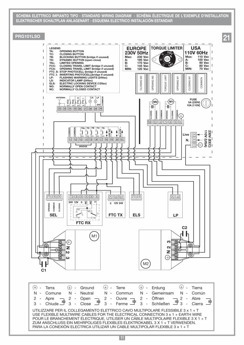
LEGEND TA: OPENING BUTTON TC: CLOSING BUTTON TB: BLOCkING BUTTON (bridge if unused) TD: DYNAMIC BUTTON (open-close) TAL: LIMITED OPENING FCC: CLOSING TRAVEL LIMIT (bridge if unused) FCA: OPENING TRAVEL LIMIT (bridge if unused) FTC_S: STOP PHOTOCELL (bridge if unused) FTC_I: INVERTING PHOTOCELL(bridge if unused) LP: FLASHING WARNING LIGHTS (24Vac) LS: INDICATOR LAMP (24Vac) ELS: ELECTRIC LOCkING DEVICE (12Vac) NO: NORMALLY OPEN CONTACT NC: NORMALLY CLOSED CONTACT
C
NO
NC
3
FUSE 5A (230V)
10A (110V)
C1
TORQUE LIMITER
Max: 110 Vac A: 100 Vac B: 90 Vac C: 80 Vac MIN: 70 Vac
230V 50Hz 110V 60Hz
230V (E
EC
) 110V
(US
A)
EUROPE USA
4
SEL
FTC Rx
FTC Tx ELS LP
UTILIZZARE PER IL COLLEGAMENTO ELETTRICO CAVO MULTIPOLARE FLESSIBILE 3 x 1 + TUSE FLEXIBLE MULTIWIRE CABLES FOR THE ELECTRICAL CONNECTION 3 x 1 + EARTH WIREPOUR LE BRANCHEMENT éLECTRIQUE, UTILISER UN CÂBLE MULTIPOLAIRE FLEXIBLE 3 X 1 + TZUM ANSCHLUSS EIN MEHRPOLIGES FLEXIBLES ELEKTROKABEL 3 X 1 + T VERWENDEN.PARA LA CONEXIÓN ELECTRICA UTILIZAR UN CABLE MULTIPOLAR FLEXIBLE 3 x 1 + T
SCHEMA ELETTRICO IMPIANTO TIPO - STANDARD WIRING DIAGRAM - SCHÉMA ÉLECTRIQUE DE L'ExEMPLE D'INSTALLATION ELEkTRISCHER SCHALTPLAN ANLAGENART - ESQUEMA ELECTRICO INSTALACIÓN ESTANDAR
PRG101LSO 21

12
• Ilpresentemanualesirivolgeapersoneabilitateall'installazionedi"APPARECCHI UTILIZZATORI DI ENERGIA ELETTRICA" e richiede una buona conoscenza della tecnica, esercitata in forma professionale e della normativa vigente. I materiali usati devono essere certificati e risultare idonei alle condizioni ambientali di installazione.
• Leoperazionidimanutenzionedevonoessereeseguitedapersonalequalificato. Prima di eseguire qualsiasi operazione di pulizia o di manutenzione, disinserire l'apparecchiatura dalla rete di alimentazione elettrica.
• Leapparecchiaturequidescrittedovrannoesseredestinatesoloall'uso per il quale sono state espressamente concepite:
"La motorizzazione di cancelli a battente ad una o due ante". Il dispositivo è adatto alla movimentazione di cancelli a battente,
ad una o due ante.
• L'applicazioneèpossibilesiaasx che a dx della luce passaggio.
• Questoprodottoèstatoprogettatoefabbricatointuttelesuepartia cura della Cardin Elettronica la quale ne ha verificato la perfetta corrispondenza delle caratteristiche con quelle richieste dalla nor-mativa vigente.
L'utilizzo dei prodotti e la loro destinazione ad usi diversi da quelli previsti e/o consigliati, non è stata sperimentata dal costruttore, pertanto i lavori eseguiti sono sotto la completa responsabilità dell'installatore.
Il costruttore non risponde qualora l'impianto elettrico non risulti conforme alle norme vigenti ed in particolare qualora il circuito di protezione (terra) non sia efficiente.
È responsabilità dell’installatore verificare le seguenti condizioni di sicurezza:
1) L’installazione deve essere sufficientemente lontana dalla strada in modo da non costituire pericolo per la circolazione.
2) L’operatore deve essere installato all’interno della proprietà ed il cancello non deve aprirsi verso l’area pubblica.
3) Il cancello motorizzato è principalmente adibito al passaggio di vetture. Dove possibile installare per pedoni un ingresso separato.
4) I comandi devono essere posti in vista, ma non entro il raggio d’azione del cancello. Inoltre quelli installati all’esterno devono essere protetti da una sicurezza tale da prevenire l’uso non autorizzato.
5) È buona norma segnalare l’automazione con targhe di avvertenza (simili a quella in figura) che devono essere facilmente visibili. Qualora l’automazione sia adibita al solo passaggio di veicoli dovranno essere poste due targhe di avvertenza di divieto di transito pedonale (una all’interno, una all’esterno).
6) Rendere consapevole l’utente che bambini o animali domestici non devono giocare o sostare nei pressi del cancello. Se necessario indicarlo in targa.
7) Qualora l’anta completamente aperta vada ad avvicinarsi ad una struttura fissa lasciando uno spazio di almeno 500 mm, tale spazio deve essere protetto con una costa sensibile antischiacciamento.
8) La bontà della connessione di terra dell’appa-recchiatura è fondamentale ai fini della sicurezza elettrica.
9) Per qualsiasi dubbio a riguardo della sicurezza dell’installazione, non procedere ma rivolgersi al distributore del prodotto.
DESCRIZIONE TECNICA200/BL203 Attuatore elettromeccanico autobloccante per ante fino a 2 m, 150 kg di peso per anta.
200/BL203L Attuatore elettromeccanico autobloccante per ante fino a 2 m, 150 kg di peso per anta. Se utilizzato con la max corsa per aperture a 90° può essere utilizzato per ante fino a 4 m, 150 kg per anta con l'aggiunta di una elettroserratura per garantire il blocco dell'anta in chiusura.
200/BL203C-200/BL203CE Attuatore elettromeccanico autobloccante per ante fino a 1,8 m, 150 kg di peso per anta. Se utilizzato con la max corsa per aperture a 90° può essere utiliz-zato per ante fino a 3 m, 150 kg per anta con l'aggiunta di una elettroserratura per garantire il blocco dell'anta in chiusura.
200/BL352 Attuatore elettromeccanico reversibile per ante fino a 3,5 m, 300 kg di peso per anta.
200/BL452 Attuatore elettromeccanico reversibile per ante fino a 4,5 m, 300 kg di peso per anta.
- Motore monofase montato su calotte in alluminio pressofuso con protezione termica incorporata.
- Carter di copertura in alluminio estruso.- Particolari sblocco in plastica antiurto.- Riduttore con ingranaggi in acciaio racchiusi in semigusci di
alluminio pressofuso (BL203-202L-202C).- Riduttore epicicloidale ad alta silenziosità e vite senza fine in
acciaio con ricircolo di sfera (BL352-452).- Staffe e particolari d'aggancio in acciaio zincato.- Lubrificazione a grasso fluido permanente.
ACCESSORI206/BL201STAP - Staffa posteriore a muro regolabile.206/BL201SUAR - Piatto anteriore regolabile per staffa
attacco cancello.980/xLSE11C - Elettroserrattura 12Vac.
I comandi minimi che possono essere installati sono APERTURA-STOP-CHIUSURA, tali comandi devono essere posti in un luogo non accessibile a bambini o minori e fuori dal raggio d’azione del cancello. Prima di procedere all'esecuzione dell'impianto verificare che la struttura da automatizzare sia in perfetta efficienza nelle sue parti fisse e mobili e realizzata in conformità alla normativa vigente. A tal fine accertarsi della sufficiente rigidità del telo cancello (se necessario intervenire con rinforzi sulla struttura) e del buon fun-zionamento dei perni (si consiglia comunque di lubrificare tutte le parti in movimento usando lubrificanti che mantengano uguali caratteristiche di attrito nel tempo e adatti a funzionare tra -20 e +70°C).
• Controllareifranchidisicurezzatrapartifisseepartimobili: - lasciare uno spazio di 30 mm minimo tra il cancello ed il pilastro
di supporto per tutta l’altezza e per tutto l’arco di apertura del cancello;
- assicurarsi che lo spazio tra il cancello ed il pavimento non superi mai 30 mm per tutto l’arco di apertura del cancello.
• Lasuperficiedelleantenondevepresentareaperture talidapermettere il passaggio della mano o del piede di persone.
• Controllarel'esattoposizionamentodiperniecerniere, il lorobuono stato di mantenimento e lubrificazione (è importante che la cerniera superiore e quella inferiore siano a piombo tra loro).
CONSIDERAZIONI GENERALI DI SICUREZZA
AVVERTENZE IMPORTANTI AVVERTENZE IMPORTANTI AVVERTENZE IMPORTANTI PER RIDURRE IL RISCHIO DI FERITE GRAVI O MORTE, LEGGERE ATTENTAMENTE LE SEGUENTI AVVERTENZE PRIMA DI PROCEDERE ALL’INSTALLAZIONE. PRESTARE PARTICOLARE ATTEN-ZIONE A TUTTE LE SEGNALAZIONI DISPOSTE NEL TESTO. IL MANCATO RISPETTO DI QUESTE POTREBBE COMPROMETTERE IL BUON FUNZIONAMENTO DEL SISTEMA.
APERTURA AUTOMATICA
NON AVVICINARSI
NON PERMETTERE A BAMBINI O AD ANIMALI DOMESTICI DI SOSTARE NEL RAGGIO D'AZIONE DEL CANCELLO
ATTENZIONE
ISTRUZIONI PER L'INSTALLAZIONE
13
SCALA: 1:2
Prodotti Technocity
BL352
16-11-98
DI0103 Description :
Product Code :
Date :
Drawing number :
P.J.Heath
CARDIN ELETTRONICA S.p.A - 31020 San Vendemiano (TV) Italy - via Raffaello, 36 Tel: 0438/401818 Fax: 0438/401831
Draft :
All rights reserved. Unauthorised copying or use of the information contained in this document is punishable by law
Scarico condensa BL352/452
A
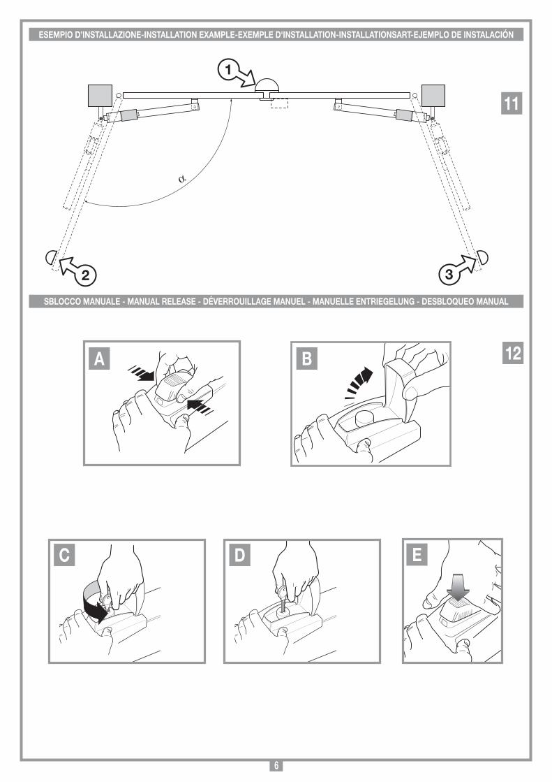
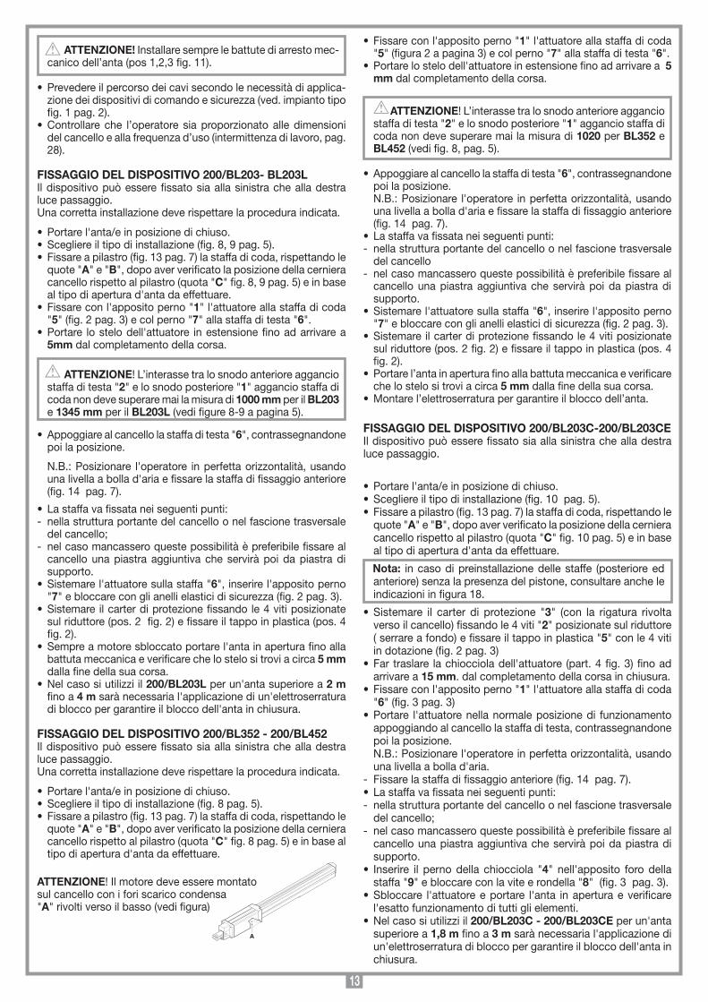
ATTENZIONE! Installare sempre le battute di arresto mec-canico dell’anta (pos 1,2,3 fig. 11).
• Prevedereilpercorsodeicavisecondolenecessitàdiapplica-zione dei dispositivi di comando e sicurezza (ved. impianto tipo fig. 1 pag. 2).
• Controllare che l’operatore sia proporzionatoalle dimensionidel cancello e alla frequenza d’uso (intermittenza di lavoro, pag. 28).
FISSAGGIO DEL DISPOSITIVO 200/BL203- BL203L Il dispositivo può essere fissato sia alla sinistra che alla destra luce passaggio.Una corretta installazione deve rispettare la procedura indicata.
• Portarel'anta/einposizionedichiuso.• Scegliereiltipodiinstallazione(fig.8,9pag.5).• Fissareapilastro(fig.13pag.7)lastaffadicoda,rispettandole
quote "A" e "B", dopo aver verificato la posizione della cerniera cancello rispetto al pilastro (quota "C" fig. 8, 9 pag. 5) e in base al tipo di apertura d'anta da effettuare.
• Fissareconl'appositoperno"1" l'attuatore alla staffa di coda "5" (fig. 2 pag. 3) e col perno "7" alla staffa di testa "6".
• Portare lostelodell'attuatore inestensionefinoadarrivarea5mm dal completamento della corsa.
ATTENZIONE! L’interasse tra lo snodo anteriore aggancio staffa di testa "2" e lo snodo posteriore "1" aggancio staffa di coda non deve superare mai la misura di 1000 mm per il BL203 e 1345 mm per il BL203L (vedi figure 8-9 a pagina 5).
• Appoggiarealcancellolastaffaditesta"6", contrassegnandone poi la posizione.
N.B.: Posizionare l'operatore in perfetta orizzontalità, usando una livella a bolla d'aria e fissare la staffa di fissaggio anteriore (fig. 14 pag. 7).
• Lastaffavafissataneiseguentipunti:- nella struttura portante del cancello o nel fascione trasversale
del cancello; - nel caso mancassero queste possibilità è preferibile fissare al
cancello una piastra aggiuntiva che servirà poi da piastra di supporto.
• Sistemarel'attuatoresullastaffa"6", inserire l'apposito perno "7" e bloccare con gli anelli elastici di sicurezza (fig. 2 pag. 3).
• Sistemareilcarterdiprotezionefissandole4vitiposizionatesul riduttore (pos. 2 fig. 2) e fissare il tappo in plastica (pos. 4 fig. 2).
• Sempreamotoresbloccatoportarel'antainaperturafinoallabattuta meccanica e verificare che lo stelo si trovi a circa 5 mm dalla fine della sua corsa.
• Nelcasosiutilizziil200/BL203L per un'anta superiore a 2 m fino a 4 m sarà necessaria l'applicazione di un'elettroserratura di blocco per garantire il blocco dell'anta in chiusura.
FISSAGGIO DEL DISPOSITIVO 200/BL352 - 200/BL452 Il dispositivo può essere fissato sia alla sinistra che alla destra luce passaggio.Una corretta installazione deve rispettare la procedura indicata.
• Portarel'anta/einposizionedichiuso.• Scegliereiltipodiinstallazione(fig.8pag.5).• Fissareapilastro(fig.13pag.7)lastaffadicoda,rispettandole
quote "A" e "B", dopo aver verificato la posizione della cerniera cancello rispetto al pilastro (quota "C" fig. 8 pag. 5) e in base al tipo di apertura d'anta da effettuare.
ATTENZIONE! Il motore deve essere montato sul cancello con i fori scarico condensa "A" rivolti verso il basso (vedi figura)
• Fissareconl'appositoperno"1" l'attuatore alla staffa di coda "5" (figura 2 a pagina 3) e col perno "7" alla staffa di testa "6".
• Portarelostelodell'attuatoreinestensionefinoadarrivarea5 mm dal completamento della corsa.
ATTENZIONE! L’interasse tra lo snodo anteriore aggancio staffa di testa "2" e lo snodo posteriore "1" aggancio staffa di coda non deve superare mai la misura di 1020 per BL352 e BL452 (vedi fig. 8, pag. 5).
• Appoggiarealcancellolastaffaditesta"6", contrassegnandone poi la posizione.
N.B.: Posizionare l'operatore in perfetta orizzontalità, usando una livella a bolla d'aria e fissare la staffa di fissaggio anteriore (fig. 14 pag. 7).
• Lastaffavafissataneiseguentipunti:- nella struttura portante del cancello o nel fascione trasversale
del cancello - nel caso mancassero queste possibilità è preferibile fissare al
cancello una piastra aggiuntiva che servirà poi da piastra di supporto.
• Sistemarel'attuatoresullastaffa"6", inserire l'apposito perno "7" e bloccare con gli anelli elastici di sicurezza (fig. 2 pag. 3).
• Sistemareilcarterdiprotezionefissandole4vitiposizionatesul riduttore (pos. 2 fig. 2) e fissare il tappo in plastica (pos. 4 fig. 2).
• Portarel’antainaperturafinoallabattutameccanicaeverificareche lo stelo si trovi a circa 5 mm dalla fine della sua corsa.
• Montarel’elettroserraturapergarantireilbloccodell’anta.
FISSAGGIO DEL DISPOSITIVO 200/BL203C-200/BL203CEIl dispositivo può essere fissato sia alla sinistra che alla destra luce passaggio.
• Portarel'anta/einposizionedichiuso.• Scegliereiltipodiinstallazione(fig.10pag.5).• Fissareapilastro(fig.13pag.7)lastaffadicoda,rispettandole
quote "A" e "B", dopo aver verificato la posizione della cerniera cancello rispetto al pilastro (quota "C" fig. 10 pag. 5) e in base al tipo di apertura d'anta da effettuare.
Nota: in caso di preinstallazione delle staffe (posteriore ed anteriore) senza la presenza del pistone, consultare anche le indicazioni in figura 18.
• Sistemare il carter di protezione "3" (con la rigatura rivolta verso il cancello) fissando le 4 viti "2" posizionate sul riduttore ( serrare a fondo) e fissare il tappo in plastica "5" con le 4 viti in dotazione (fig. 2 pag. 3)
• Fartraslare lachioccioladell'attuatore (part.4fig.3)finoadarrivare a 15 mm. dal completamento della corsa in chiusura.
• Fissareconl'appositoperno"1" l'attuatore alla staffa di coda "6" (fig. 3 pag. 3)
• Portare l'attuatorenellanormaleposizionedi funzionamentoappoggiando al cancello la staffa di testa, contrassegnandone poi la posizione.
N.B.: Posizionare l'operatore in perfetta orizzontalità, usando una livella a bolla d'aria.
- Fissare la staffa di fissaggio anteriore (fig. 14 pag. 7).• Lastaffavafissataneiseguentipunti:- nella struttura portante del cancello o nel fascione trasversale
del cancello;- nel caso mancassero queste possibilità è preferibile fissare al
cancello una piastra aggiuntiva che servirà poi da piastra di supporto.
• Inserire il perno della chiocciola "4" nell'apposito foro della staffa "9" e bloccare con la vite e rondella "8" (fig. 3 pag. 3).
• Sbloccare l'attuatoreeportare l'anta inaperturaeverificarel'esatto funzionamento di tutti gli elementi.
• Nelcasosiutilizziil200/BL203C - 200/BL203CE per un'anta superiore a 1,8 m fino a 3 m sarà necessaria l'applicazione di un'elettroserratura di blocco per garantire il blocco dell'anta in chiusura.
14
REGOLAZIONE DEL FINECORSA MECCANICO 200/BL203C - 200/BL203CE (fig. 3 pag. 3)
Il modello 200/BL203C - 200/BL203CE è provvisto di fine-corsa meccanici registrabili "7" e "10". Allentare le viti di fissaggio e portare gli anelli "7" e "10" ogniuno nel punto più opportuno di apertura e di chiusura, quindi bloccare ciascun anello con la propria vite.
L'operazione di sblocco va fatta solamente a motore fermo, per mancanza di energia elettrica.Per sbloccare l'anta del cancello munirsi della chiave in dotazione all'apparecchiatura. Essa deve essere conservata in luogo di facile reperimento, in casa, o sull'apparecchiatura stessa, utilizzando l'apposita sede per chiave.
Per sbloccare:- alzare la copertura del nottolino, premendo le pareti laterali (fig
12a-12b);- inserire la chiave di sblocco e girarla di circa 30 gradi (fig. 12c).
Il sistema si sgancia ed il nottolino sale;- nel caso si voglia mantenere sbloccato il motore, riportare la
copertura a protezione del nottolino, in posizione di chiusura (fig. 12e).
Per ribloccare:- togliere la chiave (fig. 12d), riportare la copertura in posizione e
premere con il palmo della mano fino ad ottenere il riaggancio dello sblocco;
- Conservare la chiave in un luogo sicuro.
Note: Per facilitare l'operazione se necessario muovere legger-mente l'anta cancello.
Non forzare, se si dovessero trovare punti duri spostare leggermente il cancello dalla posizione in modo da facilitare l'operazione di riaggancio, dei denti delle ruote dentate all'interno del riduttore.
Durante la manovra si deve controllare il movimento del cancello e azionare il dispositivo di arresto immediato (STOP) in caso di pericolo.
In caso di mancanza di energia elettrica il cancello può essere sbloccato manualmente utilizzando l'apposita chiave di sblocco in dotazione (vedi sblocco manuale).
Controllare periodicamente lo stato di usura dei perni ed even-tualmente ingrassare le parti in moto in particolare la vite pos. 11 fig. 3 (mod. 200/BL203C - 200/BL203CE), usando lubrificanti che mantengano uguali caratteristiche di attrito nel tempo e adatti a funzionare tra -20 e +70°C.
In caso di guasto o anomalie di funzionamento staccare l'ali-mentazione elettrica a monte dell'apparecchiatura e chiamare l'assistenza tecnica.
Verificare periodicamente il funzionamento delle sicurezze (fotocellule ecc.)
Le eventuali riparazioni devono essere eseguite da personale specializzato usando materiali originali e certificati.
L'uso dell'automazione non è idoneo all'azionamento in continuo, bensì deve essere regolato in base ai vari modelli (vedi caratteri-stiche tecniche pagina 28).
Assicurarsi prima di allacciare l'apparecchiatura che la tensione e la frequenza di rete corrisponda ai valori riportati nella targhetta caratteristiche.
• L'apparecchiaturafunzionacontensionemonofase230 V 50 Hz (vedi schema elettrico)
• Ilmotoriduttoredeveesserecollegatoadunefficaceimpiantodi messa a terra, pertanto utilizzare il morsetto contrassegnato con il simbolo che si trova sulla scatola porta morsettiera.
• Nonutilizzarecavoconconduttoriinalluminio;nonstagnarel’estremità dei cavi da inserire in morsettiera; utilizzare cavo con marcatura T min 85°C resistente agli agenti atmosferici.
•Ilcavodialimentazionedelmotoredevefareunpercorsoampiotale da non risultare teso in alcun punto.
•Ilcavonondeveesserearrotolatointornoasupporti,nondeveessere cementato nel muro.
Tra la centralina di comando e la rete deve essere inter-posto un interruttore onnipolare con distanza di apertura tra i contatti di almeno 3 mm.
•Collegaretralefasi2e3delmotoriduttore(fig.19-21pag.9-11)il condensatore fornito di serie.
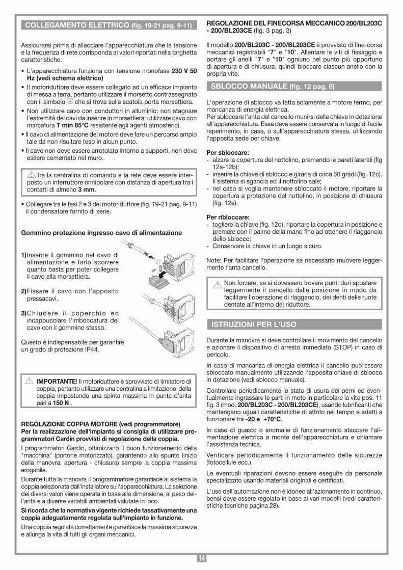
Gommino protezione ingresso cavo di alimentazione
1) Inserire il gommino nel cavo di alimentazione e farlo scorrere quanto basta per poter collegare il cavo alla morsettiera.
2) Fissare il cavo con l’apposito pressacavi.
3) Ch iude re i l cope rch io ed incappucciare l’imboccatura del cavo con il gommino stesso.
Questo è indispensabile per garantire un grado di protezione IP44.
IMPORTANTE! Il motoriduttore è sprovvisto di limitatore di coppia, pertanto utilizzare una centralina a limitazione della coppia impostando una spinta massima in punta d'anta pari a 150 N .
REGOLAZIONE COPPIA MOTORE (vedi programmatore)Per la realizzazione dell'impianto si consiglia di utilizzare pro-grammatori Cardin provvisti di regolazione della coppia.I programmatori Cardin, ottimizzano il buon funzionamento della "macchina" (portone motorizzato), garantendo allo spunto (inizio della manovra, apertura - chiusura) sempre la coppia massima erogabile.Durante tutta la manovra il programmatore garantisce al sistema la coppia selezionata dall'installatore sull'apparecchiatura. La selezione dei diversi valori viene operata in base alla dimensione, al peso del-l'anta e a diverse variabili ambientali valutate in loco.Si ricorda che la normativa vigente richiede tassativamente una coppia adeguatamente regolata sull'impianto in funzione.Una coppia regolata correttamente garantisce la massima sicurezza e allunga la vita di tutti gli organi meccanici.
COLLEGAMENTO ELETTRICO (fig. 19-21 pag. 9-11)
SBLOCCO MANUALE (fig. 12 pag. 6)
SCALA: 1:2
Prodotti Technocity
BL202
01-07-99
DI0131 Description :
Product Code :
Date :
Drawing number :
P.J.Heath
CARDIN ELETTRONICA S.p.A - 31020 San Vendemiano (TV) Italy - via Raffaello, 36 Tel: 0438/401818 Fax: 0438/401831
Draft :
All rights reserved. Unauthorised copying or use of the information contained in this document is punishable by law
Collegamento gommino protezione
12
31
23
12
3
ISTRUZIONI PER L'USO

15
TECHNICAL DESCRIPTION200/BL203 Self-locking electromechanical operator suitable for hinged gates up to 2,0 metres in length and 150 kg in weight (per gate leaf).200/BL203L Self-locking electromechanical operator suitable for hinged gates up to 2 metres in length and 150 kg in weight (per gate leaf). If used with the maximum travel distance an opening angle of 90° and the addition of an electric locking device, it can be used for gates up to 4 metres in length and 150 kg in weight. 200/BL203C - 200/BL203CE Self-locking electromechanical operator suitable for hinged gates up to 1,8 metres in length and 150 kg in weight (per gate leaf). If used with the maximum travel distance an opening angle of 90° and the addition of an electric locking device, it can be used for gates up to 3 metres in length and 150 kg in weight. 200/BL352 Reversible electromechanical operator suitable for hinged gates up to 3,5 m in length and 300 kg in weight (per gate leaf).200/BL452 Reversible electromechanical operator suitable for hinged gates up to 4,5 m in length and 300 kg in weight (per gate leaf).- Single phase motor housed in a cast aluminium case with incor-
porated overload protector .- External carter in extruded aluminium.- Release mechanism components in shockproof plastic.- Geared motor with steel gears enclosed in a die cast two-piece
aluminium shell (BL203-202L-202C).- Silent running epicycloid reduction motor with a never ending
universal ball screw in steel (BL352-452).- Brackets and accessories in zinc-plated steel.- Lubrication using permanently fluid grease.
ACCESSORIES206/BL201STAP - Adjustable rear bracket for fitting to a wall206/BL201SUAR - Adjustable rear plate for fitting to a gate980/xLSE11C - Electric locking device 12 Vac
The minimum controls which may be installed are OPEN-STOP-CLOSE, these controls must be installed in a location not accessible to children. Before starting the installation of the system check that the structure which is to be automated is in good working order and respects the local standards and regulations in force. To this end make sure that the gate is sufficiently rigid (if nec-essary reinforce the structure) and that the runner guides slide easily. You are advised to grease all the moving parts using lubri-cants which maintain unaltered friction characteristics over a period of time and are suitable for temperatures of -20 to +70°C.
• Check the safety measures between the fixed and movingparts:
- a minimum space of 30 mm must always be left along the entire distance between the gate and the support column measured throughout the entire opening angle of the gate.
- make sure that the space between the bottom of the gate and the pavement never exceeds 30 mm throughout the entire opening angle of the gate.
• Thesurfaceofthegatemustnotfeatureopeningswhichallowa person’s hand or foot to pass through.
• Checktheexactpositioningofthepivots,andtheirgoodwork-ing order (the upper and lower hinges/pivots must be aligned on the same axis).
IMPORTANT REMARkS IMPORTANT REMARkS IMPORTANT REMARkS
IMPORTANT SAFETY INSTRUCTIONS
• Theseinstructionsareaimedatprofessionallyqualified"INSTALL-ERS OF ELECTRICAL EQUIPMENT" and must respect the local standards and regulations in force. All materials used must be approved and must suit the environment in which the installation is situated.
• Allmaintenanceoperationsmustbecarriedoutbyprofessionallyqualified technicians. Before carrying out any cleaning or main-tenance operations make sure the power is disconnected at the mains.
• Thisappliancemustbeusedexclusivelyforthepurposeforwhichit has been made. "i.e. for the automation of one or two hinged gates".
The appliance may be used to operate hinged gates, with one or two gate leaves.
• Theunitmaybefittedbothtothe right and to the left of the pas-sageway.
• Thisproductandallitsrelativecomponentshasbeendesignedand manufactured by Cardin Elettronica who have verified that the product conforms in every aspect to the safety standards in force.
Any non authorised modifications are to be considered improper and therefore dangerous.
The manufacturer accepts no liability for situations arising from the use of an electrical installation which does not conform to the local standards and regulations in force and in particular when the earthing circuit is not efficient.
It is the responsibility of the installer to make sure that the following public safety conditions are satisfied:
1) Ensure that the gate operating installation is far enough away from the main road to eliminate possible traffic disruptions.
2) The operator must be installed on the inside of the property and not on the public side of the gate. The gates must not swing outwards onto a public area.
3) The gate operator is designed for use on gates through which vehi-cles are passing. Pedestrians should use a separate entrance.
4) The gate must be in full view when it is operating therefore controls must be situated in a position where the operator can see the gate at all times.
5) At least two warning signs (similar to the example on the right) should be placed, where they can be easily seen by the public, in the area of the system of automatic operation. One inside the property and one on the public side of the installation.
These signs must be indelible and not hidden by any objects (such as tree branches, decorative fencing etc.).
6) Make sure that the end-user is aware that children and/or pets must not be allowed to play within the area of a gate installation. If possible include this in the warning signs.
7) Whenever a fully open gate leaf comes within at least 500 mm of a fixed structure the space must be protected by an anticrush buffer.
8) A correct earth connection is fundamental in order to guarantee the electrical safety of the machine
9) If you have any questions about the safety of the gate operating system, do not install the operator. Contact your dealer for assistance.
TO REDUCE THE RISk OF SEVERE INJURY OR DEATH READ THE FOLLOWING REMARkS CAREFULLY BEFORE PROCEEDING WITH THE INSTALLATION. PAY PARTICULAR ATTENTION TO ALL THE PARAGRAPHS MARkED WITH THE SYMBOL . NOT READING THESE IMPORTANT INSTRUCTIONS COULD COMPROMISE THE CORRECT WORkING ORDER OF THE SYSTEM.
AUTOMATIC OPENING
kEEP CLEAR
CHILDREN OR PETS MUST NOT BE ALLOWED TO PLAY ON OR NEAR THE INSTALLATION
WARNING
INSTALLATION INSTRUCTIONS

16
SCALA: 1:2
Prodotti Technocity
BL352
16-11-98
DI0103 Description :
Product Code :
Date :
Drawing number :
P.J.Heath
CARDIN ELETTRONICA S.p.A - 31020 San Vendemiano (TV) Italy - via Raffaello, 36 Tel: 0438/401818 Fax: 0438/401831
Draft :
All rights reserved. Unauthorised copying or use of the information contained in this document is punishable by law
Scarico condensa BL352/452
A
ATTENTION! A mechanical stop buffer must be installed in both the opening and closing positions ( position 1,2,3 fig. 11).
• Workouttherunofthecablesaccordingtothecommandandcontrol devices fitted and make sure the system conforms to the local standard and regulations in force (see installation example fig. 1 pag. 2).
• Checkthattheapplianceissuitableforthesize,weightanddutycycle of the gate to which it is to be applied (see duty cycle on page 28)
FITTING THE UNITS 200/BL203- BL203LThe unit may be positioned either to the right or to the left of the passageway. To install the unit correctly carry out the following procedure carefully.
• Movethegate/stotheclosedposition.• Selectthetypeofopeningrequired(fig.8,9pag.5).• Fasten the rearmooringbracket to thecolumn (fig. 13pag.
7), taking into account the measurements "A" and "B", after having checked the position of the gate hinge with respect to the column (measurement "C" fig. 8, 9 page 5) according to the type of opening required.
• Fixthearmtotherearmooringbracket"5" using the retaining pin "1" (fig. 2 pag. 3) and the front bracket "6" using the pin "7".
• Extendthearmmanuallyuntilitreaches5 mm from the end of the travel distance.
ATTENTION! The centre distance between the front moor-ing bracket "2" and the rear mooring bracket "1" must never exceed 1000 mm for the BL203 and 1345 mm for the BL203L (see figures 8-9 on page 5)
• Movethearmtoitsnormaloperatingposition,restthehead
against the gate and mark the position of the front bracket "6".
Note: Make sure the operator is perfectly level (using a spirit level) and then fix the front bracket to the gate (fig. 14 pag. 7).
• Thefrontbracketmaybefixedinthefollowingpositions:- on the gate frame or on a horizontal cross beam, - if this is not possible, fix a reinforcing plate to the gate structure
and then fasten the front bracket onto the reinforcing plate.• Insertthearminthefrontbracket"6", insert the retaining pin
"7" and fasten down using the supplied C-clips (fig. 2 pag. 3).• Install theprotectivecarterby fastening the4screwson the
geared motor (pos. 2 fig. 2) and position the plastic protective cap (pos. 4 fig. 2).
• Withthemotorreleasedmoveitmanuallytothefullyopenposi-tion and check that all the components work correctly.
• Ifyouareusing200/BL203L with a gate from 2 to 4 metres in width an electric locking device must be fitted to ensure that the gate is blocked when it is closed.
FITTING THE UNITS 200/BL352 - 200/BL452The unit may be positioned either to the right or to the left of the passageway. To install the unit correctly carry out the following procedure carefully. • Movethegate/stotheclosedposition.• Selectthetypeofopeningrequired(fig.8pag.5).• Fasten the rear mooringbracket to the column (fig. 13 pag.
7), taking into account the measurements "A" and "B", after having checked the position of the gate hinge with respect to the column (measurement "C" fig. 8 page 5) according to the type of opening required.
ATTENTION! The motor must be installed on the gate with the humidity drain holes "A" facing downwards (see drawing)
• Fixthearmtotherearmooringbracket"5" using the retaining pin "1" (fig. 2 pag. 3) and the front bracket "6" using the pin "7".
• Extendthearmmanuallyuntilitreaches5mm from the end of the travel distance.
ATTENTION! The centre distance between the front mooring bracket "2" and the rear mooring bracket "1" must never exceed 1020 mm for the BL352 and BL452 (see figure 8 on page 5)
• Movethearmto itsnormaloperatingposition,rest thehead
against the gate and mark the position of the front bracket "6".
Note: Make sure the operator is perfectly level (using a spirit level) and then fix the front bracket to the gate (fig. 14 pag. 7).
• Thefrontbracketmaybefixedinthefollowingpositions:- on the gate frame or on a horizontal cross beam; - if this is not possible, fix a reinforcing plate to the gate structure
and then fasten the front bracket onto the reinforcing plate.• Insertthearminthefrontbracket"6", insert the retaining pin
"7" and fasten down using the supplied C-clips (fig. 2 pag. 3).• Install theprotectivecarterby fastening the4screwson the
geared motor (pos. 2 fig. 2) and position the plastic protective cap (pos. 4 fig. 2).
• Extendthearmmanuallyuntilitreaches5mm from the end of the travel distance.
• Mounttheelectriclockingdevice(locksthegateintheclosedposition).
FITTING THE UNIT 200/BL203C - 200/BL203CE
The unit may be positioned either to the right or to the left of the passageway.• Movethegate/stotheclosedposition.• Selectthetypeofopeningrequired(fig.10pag.5).• Fastentherearmooringbracket tothecolumn(fig.13pag.
7), taking into account the measurements "A" and "B", after having checked the position of the gate hinge with respect to the column (measurement "C" fig. 10 page 5) according to the type of opening required.
Note: if the gate brackets are to be pre-installed (front and rear) without the presence of the piston, you must also consult the indications in figure 18.
• Positiontheprotectivecarter"3" (with the scoring facing the gate), fasten the 4 screws "2" positioned on the geared motor (tighten them well down) and insert the plastic end cap "5" using the four supplied screws (fig. 2 pag. 3).
• Rotatetheneverendingscrew(part.4fig.3)untilitreaches15 mm from the end of the closing direction travel distance.
• Fixthearmtotherearmooringbracket"6" using the retaining pin "1" (fig. 3 pag. 3).
• Movethearmtoitsnormaloperatingposition,resttheheadagainst the gate and mark the position of the front bracket "6".
Note: Make sure the operator is perfectly level (using a spirit level).
- position the front holding bracket (fig. 14 pag. 7)• Thefrontbracketmaybefixedinthefollowingpositions:- on the gate frame or on a horizontal cross beam, - if this is not possible, fix a reinforcing plate to the gate structure
and then fasten the front bracket onto the reinforcing plate.• Inserttheretainingpinoftheneverendingscrew"4" into the
front bracket "9" and fasten down using the supplied screw and washer "8" (fig. 3 pag. 3).
• With themotor releasedmove itmanually to the fullyopenposition and check that all the components work correctly.
• Ifyouareusing200/BL203C - 200/BL203CE with a gate from 1,8 to 3 m in width an electric locking device must be fitted to ensure that the gate is blocked when it is closed.
17
SCALA: 1:2
Prodotti Technocity
BL202
01-07-99
DI0131 Description :
Product Code :
Date :
Drawing number :
P.J.Heath
CARDIN ELETTRONICA S.p.A - 31020 San Vendemiano (TV) Italy - via Raffaello, 36 Tel: 0438/401818 Fax: 0438/401831
Draft :
All rights reserved. Unauthorised copying or use of the information contained in this document is punishable by law
Collegamento gommino protezione
12
31
23
12
3
SETTING THE MECHANICAL TRAVEL LIMIT (fig. 3 pag. 3)
The model 200/BL203C - 200/BL203CE is fitted with adjust-able mechanical travel limits "7" and "10". Loosen the fastening screws and move the rings "7" and "10" to the desired opening and closing positions then tighten them carefully.
Releasing the gate should only be carried out when the motor has stopped because of blackouts.To release the gate use the plastic key supplied with the appliance. It should be stored in an easily accessible place, at home or on the appliance itself using the key slot (pos. 5 fig. 12).
To release the gears- open the lock mechanism cover by pressing on the sides (fig
12a-12b);- insert the release key and turn it through about 30 degree
(fig. 12c). The gears will be released and the lock cylinder will rise;
- if you wish leave the gears released, just close the lock cylinder cover (fig. 12e).
To lock the gears- remove the key (fig. 12d), close the cover and press down with
the palm of your hand until the gears are locked;- keep the key in a safe place.
Note: To make the operation easier the gate can be moved slightly if required.
Don't force the locking mechanism, if you encounter resistance move the gate slightly to allow the cogs to slot together more easily within the geared motor.
During the opening/closing manoeuvre check for correct operation and activate the emergency stop button in case of danger.During blackouts the gate can be released and manually manoeu-vred using the supplied release key (see manual release).Periodically check the moving parts for wear and tear and grease if required, paying particular attention to the never ending screw pos. 11 fig. 3 (200/BL203C - 200/BL203CE), using lubricants which maintain their friction levels unaltered throughout time and are suitable for temperatures of -20 to +70°C. In case of failure or operational anomalies switch off the power at the mains do not attempt to repair the appliance yourself.Periodically check the correct operation of all safety devices (photoelectric cells etc.).Eventual repair work must be carried out by specialised personnel using original spare parts. The appliance is not suitable for continuous operation and must be adjusted according to the model (see technical data on page 28).
Before connecting the appliance make sure that the voltage and frequency rated on the data plate conform to those of the mains supply.
• Theapplianceworksoffasinglephase230 V 50 Hz power supply (see wiring diagram).
• Thegearedmotormustbeearthed,tothisendusethebindingpost marked which can be found on the wiring box.
• Donotusecableswithaluminiumconductors;donotsoldertheends of cables which are to be inserted into the binding posts; use cables which are marked T min 85°C and are resistant to atmospheric agents.
• Thepowercablemusthaveenoughslacktomakesureitisnotpulled tight during normal operation.
• Thepowercablemustnotbewoundaroundanyoftheappli-ances components and must not be cemented into the wall.
An double pole circuit breaker with a minimum of 3 mm between the contacts must be installed between the electronic programmer and the mains supply.
• Connectthesuppliedcapacitorbetweenthelivewires2and3 of the geared motor (fig. 19-21 pag. 9-11).
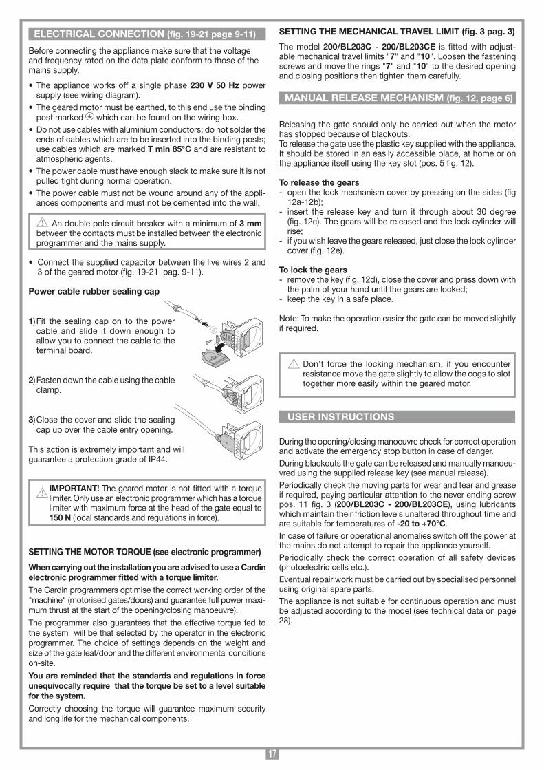
Power cable rubber sealing cap
1) Fit the sealing cap on to the power cable and slide it down enough to allow you to connect the cable to the terminal board.
2) Fasten down the cable using the cable clamp.
3) Close the cover and slide the sealing cap up over the cable entry opening.
This action is extremely important and willguarantee a protection grade of IP44.
IMPORTANT! The geared motor is not fitted with a torque limiter. Only use an electronic programmer which has a torque limiter with maximum force at the head of the gate equal to 150 N (local standards and regulations in force).
SETTING THE MOTOR TORQUE (see electronic programmer)
When carrying out the installation you are advised to use a Cardin electronic programmer fitted with a torque limiter.The Cardin programmers optimise the correct working order of the "machine" (motorised gates/doors) and guarantee full power maxi-mum thrust at the start of the opening/closing manoeuvre).The programmer also guarantees that the effective torque fed to the system will be that selected by the operator in the electronic programmer. The choice of settings depends on the weight and size of the gate leaf/door and the different environmental conditions on-site.You are reminded that the standards and regulations in force unequivocally require that the torque be set to a level suitable for the system. Correctly choosing the torque will guarantee maximum security and long life for the mechanical components.
ELECTRICAL CONNECTION (fig. 19-21 page 9-11)
MANUAL RELEASE MECHANISM (fig. 12, page 6)
USER INSTRUCTIONS

18
DESCRIPTION TECHNIQUE200/BL203 Opérateur électromécanique autobloquant pour portails battants allant jusqu'à 2 m par vantail d'un poids maximum de 150 kg. 200/BL203L Opérateur électromécanique autobloquant pour portails battants allant jusqu'à 2 m par vantail d'un poids maximum de 150 kg. En cas d'utilisation avec la course maxi. pour ouvertures à 90°, il peut être appliqué sur portails allant jusqu'à 4 m par vantail d'un poids maximum de 150 kg en ajoutant la serrure électrique pour garantir le verrouillage du portail. 200/BL203C - 200/BL203CE Opérateur électromécanique autobloquant pour portails battants allant jusqu'à 1,8 m par vantail d'un poids maximum de 150 kg. En cas d'utilisation avec la course maxi. pour ouvertures à 90°, il peut être appliqué sur portails allant jusqu'à 3 m par vantail d'un poids maximum de 150 kg en ajoutant la serrure électrique pour garantir le verrouillage du portail. 200/BL352 Opérateur électromécanique réversible pour portails battants allant jusqu'à 3,5 m par vantail d'un poids maximum de 300 kg. 200/BL452 Opérateur électromécanique réversible pour portails battants allant jusqu'à 4,5 m par vantail d'un poids maximum de 300 kg.
- Moteur monophasé monté sur calottes en aluminium moulé sous pression avec protection thermique incorporée.
- Carter de protection en aluminium extrudé.- Parties du système de déverrouillage en matière plastique anti-
choc.- Réducteur avec engrenages en acier sous boîtier constitué de deux
demi-coques en aluminium moulé sous pression (BL203-202L-202C).
- Réducteur épicycloïdal très silencieux et vis en acier à billes de transport (BL352-452).
- Pattes et éléments d'ancrage en acier galvanisé.- Lubrification permanente par graisse fluide.
ACCESSOIRES206/BL201STAP - Patte postérieure réglable, fixation murale.206/BL201SUAR - Méplat réglable pour patte antérieure,
fixation au portail980/xLSE11C-1 - Serrure électrique 12 Vac.
L'organe de commande minimum requis est une boîte à boutons OUVERTURE-STOP-FERMETURE; celle-ci devra être installée impé-rativement hors de portée de mineurs, notamment des enfants, et hors du rayon d'action du portail. Avant de réaliser l'installation, s'assurer de l'efficacité des parties fixes et mobiles de la structure à automatiser et de la conformité de celle-ci aux normes en vigueur.Dans cet objectif, s'assurer de la rigidité du tablier du portail (si néces-saire renforcer la structure) et du bon fonctionnement des pivots (il est conseillé de graisser toutes les parties mobiles avec un lubrifiant qui maintient au fil des années les caractéristiques de friction et qui est adapté à des températures oscillant entre -20° et +70°C).
• Contrôlerlesespacesdesécuritéentrelespartiesfixesetmobi-les:
- laisser un espace de 30 mm au moins, entre le vantail et le pilier de support, sur toute la hauteur et sur tout l’arc d’ouverture du portail;
- contrôler que l’espace entre le portail et le sol ne soit jamaissupérieur à 30 mm sur tout l’arc d’ouverture du portail.
• Surlasurfacedesvantauxilnedoitpasyavoird'ouverturesquipermettent le passage de la main ou du pied.
• Contrôlerl'emplacementcorrectdespivotsetdesgonds,leurbonétat et leur lubrification (le gond du haut et celui du bas doivent être parfaitement alignés).
CONSIGNES GÉNÉRALES DE SÉCURITÉ
• Celivretestdestinéàdespersonnestitulairesd'uncertificatd'ap-titude professionnelle pour l'installation des "APPAREILS ÉLEC-TRIQUES" et requiert une bonne connaissance de la technique appliquée professionnellement, ainsi que des normes en vigueur. Les matériels utilisés doivent être certifiés et être adaptés aux conditions atmosphériques du lieu d'implantation.
• Lestravauxdemaintenancenedoiventêtreeffectuésqueparunpersonnel qualifié. Avant une quelconque opération de nettoyage ou de maintenance, mettre l'appareil hors tension.
• Lesappareilsdécritsdansce livretnedoiventêtredestinésqu’àl’utilisation pour laquelle ils ont été expressément conçus à savoir: "La motorisation de portails battants à un ou deux vantaux". Le dispositif est indiqué pour la motorisation de portails battants à un ou deux vantaux.
• Touslesmodèlessontapplicablesaussibienàdroitequ’àgauchedu passage.
• Ceproduitaétéétudiéetconstruitentièrementpar laStéCardinElettronica qui a pris soin de vérifier la conformité de ses caractéris-tiques avec les exigences des normes en vigueur.
Une diverse utilisation des produits ou leur destination à un usage différent de celui prévu et/ou conseillé n'a pas été expérimentée par le Constructeur. Par conséquent, les travaux effectués sont entièrement sous la responsabilité de l'installateur.
Le Constructeur décline toute responsabilité en cas d'installation électrique non conforme aux normes en vigueur, notamment en cas de circuit de protection (mise à terre) inefficace.
Il appartient à l’installateur de vérifier les conditions de sécurité ci-dessous:
1) L’installation doit se trouver suffisamment loin de la route pour ne pas constituer de risque pour la circulation;
2) L’opérateur doit être installé à l’intérieur de la propriété et le portail ne doit pas s’ouvrir sur le domaine public;
3) Le portail automatisé est affecté principalement au passage de véhicules. Si possible, prévoir une entrée séparée pour les piétons;
4) Les organes de commande doivent être placés de façon qu’ils soient bien en vue et hors du rayon d’action du portail. En outre, ceux placés à l’extérieur doivent être protégés contre les actes de vandalisme;
5) Il est conseillé de signaler l’automatisation du portail par des panneaux de signalisation (comme celui indiqué en figure) placés bien en vue. Dans l’hypothèse où l’automatisme serait affecté exclusivement au passage de véhicules, il faudra prévoir deux panneaux d’interdiction de passage aux piétons (l’un à l’intérieur et l’autre à l’extérieur);
6) Faire prendre conscience à l’utilisateur du fait que les enfants et les animaux domestiques ne doivent pas jouer ou stationner à proximité du portail. Si nécessaire, l’indiquer sur le panneau;
7) Si le vantail, une fois qu’il est complètement ouvert, se trouve très proche d’une structure fixe, laisser un espace de au moins 500 mm dans la zone d’action du bras articulé; tel espace devra être protégé par un bord de sécurité anti-coincement.
8) Pour garantir la sécurité électrique, il est impéra-tif de brancher l’appareil à la prise de terre.
9) En cas d’un quelconque doute sur la sécurité de l’installation, interrompre la pose et contacter le distributeur du matériel.
CONSIGNES IMPORTANTES! CONSIGNES IMPORTANTES! CONSIGNES IMPORTANTES! POUR RÉDUIRE LES RISQUES DE BLESSURES GRAVES OU DE MORT, LIRE ATTENTIVEMENT LES CONSIGNES SUIVANTES AVANT DE PROCÉDER À LA POSE. PRÊTER GRANDE ATTENTION À TOUTES LES SIGNALISATIONS QUI SE TROUVENT DANS LE TExTE. LE NON RESPECT DE CES CONSIGNES POURRAIT COMPROMETTRE LE BON FONCTIONNEMENT DU SYSTÈME.
FERMETURE AUTOMATISÉE
NE PAS S'APPROCHER
NE PAS PERMETTRE AUx ENFANTS ET AUx ANIMAUx DOMESTIQUES DE STATIONNERDANS LE RAYON D'ACTION DU PORTAIL
ATTENTION
INSTRUCTIONS POUR L’INSTALLATION

19
SCALA: 1:2
Prodotti Technocity
BL352
16-11-98
DI0103 Description :
Product Code :
Date :
Drawing number :
P.J.Heath
CARDIN ELETTRONICA S.p.A - 31020 San Vendemiano (TV) Italy - via Raffaello, 36 Tel: 0438/401818 Fax: 0438/401831
Draft :
All rights reserved. Unauthorised copying or use of the information contained in this document is punishable by law
Scarico condensa BL352/452
A
ATTENTION ! Il est impératif d'installer des butées d'arrêt du vantail (pos. 1, 2, 3 fig. 11).
• Prévoirleparcoursdescâblesenfonctiondesdispositifsdecom-mande et de sécurité imposés par les normes de sécurité en vigueur (voir exemple d'installation fig. 1 page 2).
• Contrôlerquel'opérateursoitadaptéauxdimensionsduportailetà la fréquence d'utilisation (intermittence de travail, page 28).
FIxATION DU DISPOSITIF 200/BL203- BL203LLe dispositif peut être fixé aussi bien à droite qu'à gauche du pas-sage. Pour une installation correcte, observer scrupuleusement les instructions ci-dessous.
• Fermerle(s)vantail(aux).• Choisirletyped'installation(fig.8,9page5).• Fixer lapattepostérieureaupilier (fig.13page7)enrespectant
les cotes "A" et "B",aprèsavoircontrôlélapositiondugondparrapport au pilier (cote "C" fig. 8, 9 page 5) et en fonction du type d'ouverture à réaliser.
• Assemblerl'opérateuràlapattepostérieure "5" au moyen de l'axe "1" (fig. 2 page 3) et à la patte antérieure "6" au moyen de l'axe "7".
•Fairesortirlatigedel'opérateurjusqu'àcequ'ellearriveà5mm de la fin de la course.
ATTENTION ! L'écartement entre l'articulation de la patte antérieure "2" et l'articulation de la patte postérieure "1" ne doit en aucun cas être supérieur à 1000 mm pour le BL203 et à 1345 mm pour le BL203L (voir figures 8-9 page 5).
•Poser lapatteantérieure "6" contre le portail et marquer ensuite sa position.
N.B.: à l'aide d'un niveau à bulle, positionner l'opérateur horizontale-ment et fixer la patte de fixation antérieure (fig. 14 page 7).
• Lapattedoitêtrefixéeauxpointssuivants:- à la structure portante du portail ou à la traverse du portail;- si la fixation aux éléments susmentionnés n'est pas possible, il
est préférable de fixer au portail une plaque qui servira ensuite de support.
• Assemblerensuitel'opérateuràlapatte "6" par l'intermédiaire de l'axe "7" et bloquer au moyen des circlips (fig. 2 page 3).
• Procéderàlamiseenplaceducarterdeprotectionenvissantles4 vis qui se trouvent sur le réducteur (pos. 2 fig. 2) et fixer le capot d'extrémité en plastique (pos. 4 fig. 2).
• Toujoursavecmoteurdéverrouillé,ouvrirlevantailjusqu'àlabutéeetcontrôlerque latigesetrouveàenviron5mm de la fin de sa course.
• Encasd'applicationdu 200/BL203L sur un vantail d'une longueur supérieure à 2 m, jusqu'à un maximum de 4 m, l'installation d'une serrure électrique s'impose pour garantir le verrouillage du portail.
FIxATION DU DISPOSITIF 200/BL352 - 200/BL452Le dispositif peut être fixé aussi bien à droite qu'à gauche du pas-sage. Pour une installation correcte, observer scrupuleusement les instructions ci-dessous.
• Fermerle(s)vantail(aux).• Choisirletyped'installation(fig.8page5).• Fixerlapattepostérieureaupilier(fig.13page7)enrespectantles
cotes "A" et "B",aprèsavoircontrôlélapositiondugondparrapportau pilier (cote "C" fig. 8 page 5) et en fonction du type d'ouverture à réaliser.
ATTENTION ! Le moteur doit être monté sur le portail en veillant à ce que les trous d'évacuation "A" des condensats soient dirigés vers le bas (voir figure).
• Assemblerl'opérateuràlapattepostérieure "5" au moyen de l'axe "1" (fig. 2 page 3) et à la patte antérieure "6" au moyen de l'axe "7".
• Fairesortirlatigedel'opérateurjusqu'àcequ'ellearriveà5mm de la fin de la course.
ATTENTION ! L'écartement entre l'articulation de la patte antérieure "2" et l'articulation de la patte postérieure "1" ne doit en aucun cas être supérieur à 1020 mm pour le BL352 et le BL452 (voir figure 8 page 5).
• Poserlapatteantérieure "6" contre le portail et marquer ensuite sa position.
N.B.: à l'aide d'un niveau à bulle, positionner l'opérateur horizon-talement et fixer la patte de fixation antérieure (fig. 14 page 7).
• Lapattedoitêtrefixéeauxpointssuivants:- à la structure portante du portail ou à la traverse du portail;- si la fixation aux éléments susmentionnés n'est pas possible, il
est préférable de fixer au portail une plaque qui servira ensuite de support.
• Assemblerensuitel'opérateuràlapatte "6" par l'intermédiaire de l'axe "7" et bloquer au moyen des circlips (fig. 2 page 3).
• Procéderàlamiseenplaceducarterdeprotectionenvissantles4 vis qui se trouvent sur le réducteur (pos. 2 fig. 2) et fixer le capot d'extrémité en plastique (pos. 4 fig. 2).
• Ouvrirlevantailjusqu'àlabutéeetcontrôlerquelatigesetrouveà environ 5mm de la fin de sa course.
FIxATION DU DISPOSITIF 200/BL203C - 200/BL203CELe dispositif peut être fixé aussi bien à droite qu'à gauche du pas-sage.
• Fermerle(s)vantail(aux).• Choisirletyped'installation(fig.10page5).• Fixer lapattepostérieureaupilier (fig.13page7)enrespectant
les cotes "A" et "B",aprèsavoircontrôlélapositiondugondparrapport au pilier (cote "C" fig. 10 page 5) et en fonction du type d'ouverture à réaliser.
Nota: en cas de pré-montage des pattes (postérieure et anté-rieure) sans la présence du piston, voir également les indications en figure 18.
• Procéderàlamiseenplaceducarterdeprotection"3" (avec rainures dirigées vers le portail) en serrant les 4 vis "2" qui se trouvent sur le réducteur (serrer à fond) et fixer le capot d'extrémité en plastique "5" au moyen des 4 vis fournies en dotation (fig. 2 page 3).
• Fairedéplacerlanoixdel'opérateur(dét.4fig.3)defaçonqu'ellearrive à 15 mm de la fin de la course en fermeture.
• Assemblerl'opérateuràlapattepostérieure "6" au moyen de l'axe "1" (fig. 3 page 3).
• Placerl'opérateurenpositionnormaledefonctionnementetposerla patte antérieure contre le portail. Marquer ensuite sa position.
N.B.: à l'aide d'un niveau à bulle, positionner l'opérateur horizon-talement.
- Fixer la patte de fixation antérieure (fig. 14 page 7).• Lapattedoitêtrefixéeauxpointssuivants:- à la structure portante du portail ou à la traverse du portail;- si la fixation aux éléments susmentionnés n'est pas possible, il
est préférable de fixer au portail une plaque qui servira ensuite de support.
• Engagerensuitelepivotdelanoix "4" dans le trou prévu à cet effet sur la patte "9" et bloquer au moyen du vis "8" (fig. 3 page 3).
• Déverrouillerl'opérateur,ouvrirlevantailets'assurerdubonfonc-tionnement de tous les éléments.
• Encasd'applicationdu200/BL203C - 200/BL203CE sur un van-tail d'une longueur supérieure à 1,8 m, jusqu'à un maximum de 3 m, l'installation d'une serrure électrique s'impose pour garantir le verrouillage du portail.
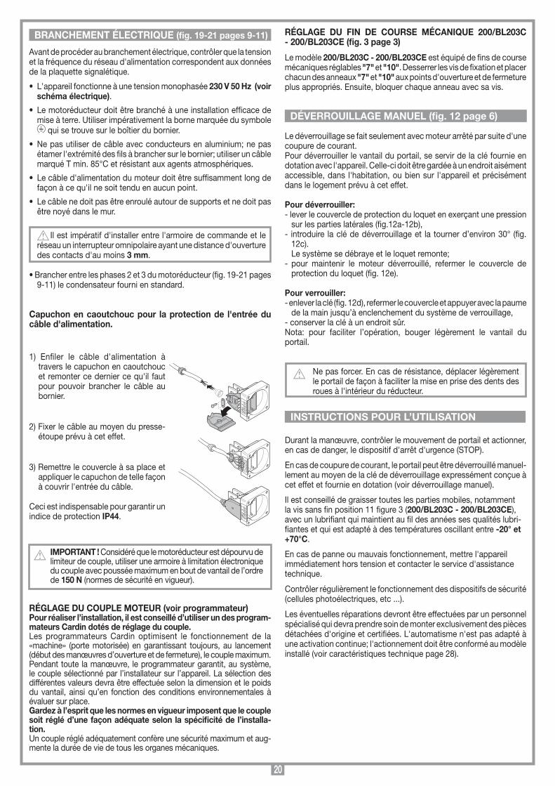
20
SCALA: 1:2
Prodotti Technocity
BL202
01-07-99
DI0131 Description :
Product Code :
Date :
Drawing number :
P.J.Heath
CARDIN ELETTRONICA S.p.A - 31020 San Vendemiano (TV) Italy - via Raffaello, 36 Tel: 0438/401818 Fax: 0438/401831
Draft :
All rights reserved. Unauthorised copying or use of the information contained in this document is punishable by law
Collegamento gommino protezione
12
31
23
12
3
Avantdeprocéderaubranchementélectrique,contrôlerquelatensionet la fréquence du réseau d'alimentation correspondent aux données de la plaquette signalétique.
• L'appareilfonctionneàunetensionmonophasée 230 V 50 Hz (voir schéma électrique).
• Lemotoréducteurdoitêtrebranchéàuneinstallationefficacedemise à terre. Utiliser impérativement la borne marquée du symbole
qui se trouve sur le boîtier du bornier.
• Nepasutiliserdecâbleavecconducteursenaluminium;nepasétamer l'extrémité des fils à brancher sur le bornier; utiliser un câble marqué T min. 85°C et résistant aux agents atmosphériques.
• Lecâbled'alimentationdumoteurdoitêtresuffisammentlongdefaçon à ce qu'il ne soit tendu en aucun point.
• Lecâblenedoitpasêtreenrouléautourdesupportsetnedoitpasêtre noyé dans le mur.
Il est impératif d'installer entre l'armoire de commande et le
réseau un interrupteur omnipolaire ayant une distance d'ouverture des contacts d'au moins 3 mm.
•Brancherentrelesphases2et3dumotoréducteur(fig.19-21pages9-11) le condensateur fourni en standard.
Capuchon en caoutchouc pour la protection de l'entrée du câble d'alimentation.
1) Enfiler le câble d'alimentation à travers le capuchon en caoutchouc et remonter ce dernier ce qu'il faut pour pouvoir brancher le câble au bornier.
2) Fixer le câble au moyen du presse-étoupe prévu à cet effet.
3) Remettre le couvercle à sa place et appliquer le capuchon de telle façon à couvrir l'entrée du câble.
Ceci est indispensable pour garantir un indice de protection IP44.
IMPORTANT ! Considéré que le motoréducteur est dépourvu de limiteur de couple, utiliser une armoire à limitation électronique du couple avec poussée maximum en bout de vantail de l’ordre de 150 N (normes de sécurité en vigueur).
RÉGLAGE DU COUPLE MOTEUR (voir programmateur)Pour réaliser l’installation, il est conseillé d’utiliser un des program-mateurs Cardin dotés de réglage du couple.Les programmateurs Cardin optimisent le fonctionnement de la «machine» (porte motorisée) en garantissant toujours, au lancement (début des manœuvres d’ouverture et de fermeture), le couple maximum. Pendant toute la manœuvre, le programmateur garantit, au système, le couple sélectionné par l’installateur sur l’appareil. La sélection des différentes valeurs devra être effectuée selon la dimension et le poids du vantail, ainsi qu’en fonction des conditions environnementales à évaluer sur place.Gardez à l’esprit que les normes en vigueur imposent que le couple soit réglé d’une façon adéquate selon la spécificité de l’installa-tion. Un couple réglé adéquatement confère une sécurité maximum et aug-mente la durée de vie de tous les organes mécaniques.
RÉGLAGE DU FIN DE COURSE MÉCANIQUE 200/BL203C - 200/BL203CE (fig. 3 page 3)
Le modèle 200/BL203C - 200/BL203CE est équipé de fins de course mécaniques réglables "7" et "10". Desserrer les vis de fixation et placer chacun des anneaux "7" et "10" aux points d'ouverture et de fermeture plus appropriés. Ensuite, bloquer chaque anneau avec sa vis.
Le déverrouillage se fait seulement avec moteur arrêté par suite d'une coupure de courant. Pour déverrouiller le vantail du portail, se servir de la clé fournie en dotation avec l'appareil. Celle-ci doit être gardée à un endroit aisément accessible, dans l'habitation, ou bien sur l'appareil et précisément dans le logement prévu à cet effet.
Pour déverrouiller:- lever le couvercle de protection du loquet en exerçant une pression
sur les parties latérales (fig.12a-12b),- introduire la clé de déverrouillage et la tourner d’environ 30° (fig.
12c). Le système se débraye et le loquet remonte;- pour maintenir le moteur déverrouillé, refermer le couvercle de
protection du loquet (fig. 12e).
Pour verrouiller:- enlever la clé (fig. 12d), refermer le couvercle et appuyer avec la paume
de la main jusqu’à enclenchement du système de verrouillage,- conserver la clé à un endroit sûr.Nota: pour faciliter l’opération, bouger légèrement le vantail du portail.
Ne pas forcer. En cas de résistance, déplacer légèrement le portail de façon à faciliter la mise en prise des dents des roues à l'intérieur du réducteur.
Durantlamanœuvre,contrôlerlemouvementdeportailetactionner,en cas de danger, le dispositif d'arrêt d'urgence (STOP).
En cas de coupure de courant, le portail peut être déverrouillé manuel-lement au moyen de la clé de déverrouillage expressément conçue à cet effet et fournie en dotation (voir déverrouillage manuel).
Il est conseillé de graisser toutes les parties mobiles, notamment la vis sans fin position 11 figure 3 (200/BL203C - 200/BL203CE), avec un lubrifiant qui maintient au fil des années ses qualités lubri-fiantes et qui est adapté à des températures oscillant entre -20° et +70°C.
En cas de panne ou mauvais fonctionnement, mettre l'appareil immédiatement hors tension et contacter le service d'assistance technique.
Contrôlerrégulièrementlefonctionnementdesdispositifsdesécurité(cellules photoélectriques, etc ...).
Les éventuelles réparations devront être effectuées par un personnel spécialisé qui devra prendre soin de monter exclusivement des pièces détachées d'origine et certifiées. L'automatisme n'est pas adapté à une activation continue; l'actionnement doit être conformé au modèle installé (voir caractéristiques technique page 28).
DÉVERROUILLAGE MANUEL (fig. 12 page 6)
BRANCHEMENT ÉLECTRIQUE (fig. 19-21 pages 9-11)
INSTRUCTIONS POUR L’UTILISATION

21
TECHNISCHE BESCHREIBUNG200/BL203 Selbsthemmender elektromechanischer Antrieb für Torflügel von bis zu 2,0 m, 150 kg je Torflügel.200/BL203L Selbsthemmender elektromechanischer Antrieb für Torflügel von bis zu 2,0 m, 150 kg je Torflügel. Bei maximalen Öff-nungsweiten von 90° ist dessen Anwendung bei Torflügeln von bis zu 4,0 m, 150 kg je Torflügel mit zusätzlich eines Elektroschlosses zur sicheren Verriegelung bei geschlossenem Flügel möglich.200/BL203C - 200/BL203CE Selbsthemmender elektromecha-nischer Antrieb für Torflügel von bis zu 1,80 m, 150 kg je Torflügel. Bei maximalen Öffnungsweiten von 90° ist dessen Anwendung bei Torflügeln von bis zu 3,0 m, 150 kg je Torflügel mit zusätzlich eines Elektroschlosses zur sicheren Verriegelung bei geschlossenem Flügel möglich. 200/BL352 Reversibler elektromechanischer Antrieb für Torflügel von bis zu 3,5 m, 300 kg je Torflügel. 200/BL452 Reversibler elektromechanischer Antrieb für Torflügel von bis zu 4,5 m, 300 kg je Torflügel.
- Einphasenmotor auf Aluminiumpressgusskappen montiert mit eingebautem Wärmeschutz.
- Schutzgehäuse aus Fliesspressaluminium.- Entriegelungsteile aus stossfestem Kunststoffmaterial.- Untersetzungsgetriebe mit Stahlzahnrädern in Aluminiumpressgusshalbschale eingeschlossen (BL203-202L-
202C).- Sehr geräuscharmes epizyklisches Untersetzungsgetriebe und
Transportkugelgewindetrieb aus Stahl (BL352-452).- Haltebügel und Halteteile aus verzinktem Stahl.- Dauerschmierung durch Flüssigfett.
ZUBEHöR206/BL201STAP - Hinterer Haltebügel an Wand, einstellbar.206/BL201SUAR - Vordere einstellbare Platte für Tor
befestigungsbügel.980/xLSE11C - Elektroschloss 12 Vac.
Die Minimalbefehle, die installiert werden können, sind OFFNEN-STOP-SCHLIESSEN. Diese Befehle müssen von einer Stelle ausführbar sein, die sich außerhalb des Aktionsradiuses des Tores befindet und für Kinder und Minderjährige unzugänglich ist. Vor der Installation ist zu überprüfen, dass die zu automatisierende Einrich-tung in ihren festen und beweglichen Teilen einwandfrei funktioniert und entsprechend den geltenden Richtlinien ausgeführt wurde.Anschließend ist die ausreichende Robustheit des Torrahmens (falls notwendig die Struktur verstärken) und die gute Funktionsweise der Bolzen (es ist ratsam alle beweglichen Teile mit Schmiermitteln zu schmieren, die die Reibungseigenschaften über die Zeit gleichhalten und für einen Temperaturbereich von -20°C bis +70°C geeignet sind) sicherzustellen.
• DieSicherheitsfreiräumezwischendenfestenundbeweglichenTeilen kontrollieren:
- auf der gesamten Höhe und Öffnungsweite der Tores einen Frei-raum von min. 30 mm zwischen dem Tor und dem Torpfeiler lassen;
- sich vergewissern, dass der Raum zwischen Tor und Boden auf der gesamten Öffnungsweite der Tores niemals mehr als 30 mm beträgt.
• DieTorflügelflächensolltenkeineoffenenStellenaufweisen,dieden Durchlass von Händen oder Füßen gestatten.
• DieexaktePositionierungderBolzenundScharniere,derengutenErhaltungsgrad und Schmierung (es ist wichtig, dass das obere und untere Scharnier lotrecht zueinander stehen) kontrollieren.
EINIGE BETRACHTUNGEN ZUR SICHERHEIT
• Das vorliegende Handbuch wendet sich an Personen, die zurInstallation von "ELEkTROGERäTEN" befähigt sind und setzt gute technische Kenntnisse und die Kenntnis der geltenden Vorschriften voraus. Die verwendeten Materialien müssen zertifiziert sein und für die Umweltbedingungen der Installation geeignet sein.
• Die Wartungsarbeiten müssen von qualifiziertem Fachpersonalausgeführt werden. Bevor irgendwelche Säuberungs- oder War-tungsarbeiten ausgeführt werden, ist die Apparatur vom Stromnetz zu trennen.
• Die hier beschriebenen Geräte dürfen nur für die Verwendungeingesetzt werden, für die sie ausdrücklich konzipiert wurden, d.h. "Die Bewegung von Drehtoren mit einem oder zwei Flügeln". Die Vorrichtung ist für das Bewegen von Flügeltoren mit einem oder zwei Flügeln bestimmt.
• DieVorrichtungkannsowohlaufderlinken als auch auf der rechten Seite der Durchfahrt befestigt werden:
• DieseVorrichtung wurde in allen ihren Teilen von der Cardin Elettronica entwickelt und hergestellt und von ihr bezüglich dessen perfekte Übereinstimmung mit den geltenden Bestimmungen überprüft.
Die Anwendung und Nutzung der Produkte zu einem anderen Zweck, als es vorgesehen und/oder geraten wurde, ist nicht vom Hersteller erprobt worden. Die Installationsarbeiten erfolgen daher unter der vollständigen Verantwortung des Installateurs.
Der Hersteller lehnt jegliche Verantwortung ab, wenn die elektrische Anlage nicht den geltenden Richtlinien entspricht und insbesondere wenn der Schutzkreislauf (Erdung) nicht leistungsfähig ist.
Es unterliegt der Verantwortung des Installateurs, die nachstehenden Sicherheitsbedingungen zu überprüfen:1) Die Installation sollte einen ausreichenden Abstand von der
Strasse haben, so dass sie keine Gefahr für den Strassenverkehr darstellt.
2) Der Antrieb muss innerhalb des Privatgeländes installiert und das Tor darf nicht in Richtung öffentlichen Eigentums geöffnet werden.
3) Die Torautomatisierung ist prinzipiell für die Durchfahrt von Autos konzipiert worden. Wenn möglich sollte für die Fußgänger ein eigener Eingang geschaffen werden.
4) Die Bedienungsschalter sollten gut sichtbar aber außerhalb des Aktionsradiuses des Tores installiert werden. Desweiteren sollten die aussen installierten Bedienungsschalter durch eine Schutzvor-richtung vor unzulässiger Bedienung geschützt werden.
5) Es ist wichtig die Automatisierung durch gut sichtbare Hinweisschil-der (wie in der Abbildung angezeigt) kenntlich zu machen. Falls die Automatisierung nur für die Durchfahrt von Autos vorgesehen ist, müssen zwei Schilder mit dem Hinweis auf Durchgangsverbot für Fußgänger intern und extern angebracht werden.
6) Der Benutzer sollte sich bewusst sein, dass Kinder oder Haustiere nicht am Tor spielen oder verweilen dürfen. Falls nötig sollte dies auf dem Hinweisschild angezeigt werden.
7) Falls der Torflügel sich bei seiner vollständigen Öffnung einer festen Struktur nähert, muss ein Freiraum von mindestens 500 mm im Arbeitsbereich des Torflügels gelassen werden. Dieser Raum muss von einer Sicherheitsleiste zum Schutz vor Quetschungen geschützt werden.
8) Die Güte des Erdungsanschlusses der Appa-ratur ist fundamental für die Sicherheit der Elektrik.
9) Bei irgendwelchen Zweifeln bezüglich der Sicherheit bei der Installation, die Arbeit ein-stellen und sich an den Vertrieb der Produkte wenden.
WICHTIGE HINWEISE WICHTIGE HINWEISE WICHTIGE HINWEISE ZUR VERRINGERUNG DER VERLETZUNGS- ODER TODESGEFAHR SOLLTEN DIE NACHSTEHENDEN HINWEISE VOR DER INSTALLATION AUFMERkSAM GELESEN WERDEN. BESONDERE AUFMERk-SAMkEIT SOLLTE ALLEN IM TExT BEFINDLICHEN HINWEISEN GESCHENkT WERDEN. DEREN NICHTBEACHTUNG köNNTE DEN ORDENTLICHEN BETRIEB DES SYSTEMS BEEINTRäCHTIGEN.
AUTOMATISCHE öFFNUNG
ABSTAND HALTEN
kINDER ODER HAUSTIEREDüRFEN SICH NICHT IN REICH-WEITE DES TORES AUFHALTEN
ACHTUNG
ANLEITUNGEN ZUR INSTALLATION

22
SCALA: 1:2
Prodotti Technocity
BL352
16-11-98
DI0103 Description :
Product Code :
Date :
Drawing number :
P.J.Heath
CARDIN ELETTRONICA S.p.A - 31020 San Vendemiano (TV) Italy - via Raffaello, 36 Tel: 0438/401818 Fax: 0438/401831
Draft :
All rights reserved. Unauthorised copying or use of the information contained in this document is punishable by law
Scarico condensa BL352/452
A
• DenAntriebamhinterenHaltebügel"5" mit dem dafür vorge-sehenen Bolzen "1" (Abb. 2, S. 3) und mit dem Bolzen "7" am vorderen Haltebügel "6" befestigen.
• DenAntriebstabbisauf5 mm über die Arbeitsstrecke hinaus herausziehen.
ACHTUNG! Der Abstand zwischen der vorderen Gelenk-kupplung des Haltebügels am Kopfende "2" und der hinteren Gelenkkupplung "1" des Haltebügels am hinteren Ende darf niemals mehr als 1020 mm beim BL352 und beim BL452 betragen (siehe Abbildung 8 auf Seite 5).
•VorderenHaltebügel"6" an das Tor anlegen und dessen Position kennzeichnen.
HINWEIS: Zur perfekt waagerechten Positionierung des Antriebes Wasserwaage verwenden und vorderen Haltebügel befestigen (Abb. 14, S. 7).
• DerHaltebügelistinderfolgendenWeisezubefestigen:- an der Trägerstruktur des Tores oder am querlaufenden Torbal-
ken;- falls diese Möglichkeit nicht besteht, ist es empfehlenswert am Tor
eine Extraplatte anzubringen, die als Befestigungsplatte dient.• Den Antrieb an den Haltebügel "6" anlegen, den Bolzen "7"
einsetzen und mit den elastischen Sicherheitsringen blockieren (Abb. 2, S. 3).
• Die Schutzabdeckung mittels der 4 auf dem Getriebemotorbefindlichen Schrauben (Pos. 2, Abb. 2) anbringen und die kappe aus Kunststoffmaterial aufsetzen (Pos. 4, Abb. 2).
• DenTorflügelbiszummechanischenEndanschlagöffnenundprüfen, ob sich der Antriebstab 5 mm vom Ende der Arbeitsstrecke befindet.
• DasElektroschlosszurVerriegelungdesTorflügelsmontieren.
ANBRINGUNG DER VORRICHTUNG 200/BL203C-200/BL203CEDie Vorrichtung kann sowohl links als auch rechts von der Durchfahrt angebracht werden.
• Den/dieTorflügelschließen.• DenInstallationstypwählen(Abb.10,S.5).• DenhinterenHaltebügelanderSäule(Abb.13,S.7)anbringen,
wobei die Masse "A" und "B" nach Prüfung der Positionierung des Torscharniers gegenüber der Säule (Maß "C" Abb. 10 S. 5) und gemäß der auszuführenden Öffnungsart des Torflügels beachtet werden müssen.
Hinweis: Bei einer Vorinstallation der Bügel (hinten und vorne) ohne Vorhandensein des Kolbens sind auch die Angaben in Abb. 18 zu berücksichtigen.
• DieSchutzabdeckung "3" (mit den Rillen in Richtung Tor) mittels der 4 auf dem Getriebemotor befindlichen Schrauben "2" (bis zum Anschlag anziehen) anbringen und die Kappe aus Kunststoffma-terial "5" mittels den 4 mitgelieferten Schrauben befestigen (Abb. 3, S. 3).
• DieGewindeschneckedesAntriebes(Teil4,Abb.3)bisauf15 mm über die Schließungsstrecke hinausbewegen.
• DenAntriebamhinterenHaltebügel "6" mit dafür vorgesehenem Bolzen "1" (Abb. 3 S. 3) befestigen.
• DenAntriebindienormaleBetriebspositionstellen,wobeidasvorderen Haltebügel am Tor anliegen sollte, um die Position kennzeichnen zu können.
HINWEIS: Zur perfekt waagerechten Positionierung des Antriebes Wasserwaage verwenden.
- Vorderen Haltebügel befestigen (Abb. 14, S. 7).• DerHaltebügelistinderfolgendenWeisezubefestigen:- an der Trägerstruktur des Tores oder am querlaufenden Torbalken;- falls diese Möglichkeit nicht besteht, ist es empfehlenswert am Tor
eine Extraplatte anzubringen, die als Befestigungsplatte dient.•DenBolzenderGewindeschnecke "4" in das dafür vorgesehene
Loch im Haltebügel "9" einsetzen und mittels der schraube "8" blockieren (Abb. 3, S. 3).
• DenAntriebentriegelnunddenTorflügelöffnenundalleElementeauf deren korrekte Funktionsweise prüfen.
•Fallsdie 200/BL203C - 200/BL203CE für Torflügel von mehr als 1,8 m bis 3 m verwendet wird, ist die Anbringung eines Elektro-schlosses zur Verriegelung des Torflügels im geschlossenen Zustand notwendig.
ACHTUNG! Mechanische Endanschläge des Torflügels immer installieren (Pos. 1, 2, 3 Abb. 11).
• Den Kabelverlauf gemäß den Installationserfordernissen derSteuer- und Sicherheitsvorrichtungen gemäß den Sicherheits-normen (siehe Anlagenart Abb. 1, S. 2) vorbereiten.
• Sicherstellen,dassderAntriebderTorgrößeundderGebrauchs-frequenz (Arbeitsintermittenz Seite 28) proportional ist.
ANBRINGUNG DER VORRICHTUNG 200/BL203- BL203LDie Vorrichtung kann sowohl links als auch rechts von der Durchfahrt angebracht werden.Zur korrekten Installation muss die angegebene Verfahrensweise beachtet werden.
• Den/dieTorflügelschließen.• DenInstallationstypwählen(Abb.8-9,S.5).• DenhinterenHaltebügelanderSäule(Abb.13,S.7)anbringen,
wobei die Masse "A" und "B" nach Prüfung der Positionierung des Torscharniers gegenüber der Säule (Maß "C" Abb. 8, 9 S. 5) und gemäß der auszuführenden Öffnungsart des Torflügels beachtet werden müssen.
• DenAntriebamhinterenHaltebügel"5" mit dem dafür vorge-sehenen Bolzen "1" (Abb. 2, S. 3) und mit dem Bolzen "7" am vorderen Haltebügel "6" befestigen.
• DenAntriebstabbisauf5 mm über die Arbeitsstrecke hinaus herausziehen.
ACHTUNG! Der Abstand zwischen der vorderen Gelenk-kupplung des Haltebügels am Kopfende "2" und der hinteren Gelenkkupplung "1" des Haltebügels am hinteren Ende darf niemals mehr als 1000 mm beim BL203 und 1345 mm beim BL203L betragen (siehe Abbildung 8-9 auf Seite 5).
•VorderenHaltebügel"6" an das Tor anlegen und dessen Position kennzeichnen.
HINWEIS: Zur perfekt waagerechten Positionierung des Antriebes Wasserwaage verwenden und vorderen Haltebügel befestigen (Abb. 14, S. 7).
• DerHaltebügelistinderfolgendenWeisezubefestigen:- an der Trägerstruktur des Tores oder am querlaufenden Torbal-
ken;- falls diese Möglichkeit nicht besteht, ist es empfehlenswert am Tor
eine Extraplatte anzubringen, die als Befestigungsplatte dient.• Den Antrieb an den Haltebügel "6" anlegen, den Bolzen "7"
einsetzen und mit den elastischen Sicherheitsringen blockieren (Abb. 2, S. 3).
• Die Schutzabdeckung mittels der 4 auf dem Getriebemotorbefindlichen Schrauben (Pos. 2, Abb. 2) anbringen und die kappe aus Kunststoffmaterial aufsetzen (Pos. 4, Abb. 2).
• Bei entriegeltem Motor den Torflügel bis zum mechanischenEndanschlag öffnen und prüfen, ob sich der Antriebstab 5 m vom Ende der Arbeitsstrecke befindet.
• Falls die 200/BL203L für Torflügel von mehr als 2 m bis 4 m verwendet wird, ist die Anbringung eines Elektroschlosses zur Verriegelung des Torflügels im geschlossenen Zustand notwen-dig.
ANBRINGUNG DER VORRICHTUNG 200/BL352-200/BL452Die Vorrichtung kann sowohl links als auch rechts von der Durchfahrt angebracht werden.Zur korrekten Installation muss die angegebene Verfahrensweise beachtet werden.
• Den/dieTorflügelschließen.• DenInstallationstypwählen(Abb.8,S.5).• DenhinterenHaltebügelanderSäule(Abb.13,S.7)anbringen,
wobei die Masse "A" und "B" nach Prüfung der Positionierung des Torscharniers gegenüber der Säule (Maß "C" Abb. 8 S. 5) und gemäß der auszuführenden Öffnungsart des Torflügels beachtet werden müssen.
ACHTUNG! Den Motor so an das Tor montieren, dass die Kondenswasserablasslöcher"A" nach unten zeigen (siehe Abbildung).
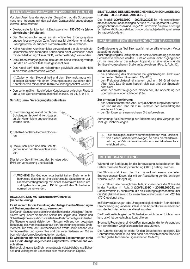
23
SCALA: 1:2
Prodotti Technocity
BL202
01-07-99
DI0131 Description :
Product Code :
Date :
Drawing number :
P.J.Heath
CARDIN ELETTRONICA S.p.A - 31020 San Vendemiano (TV) Italy - via Raffaello, 36 Tel: 0438/401818 Fax: 0438/401831
Draft :
All rights reserved. Unauthorised copying or use of the information contained in this document is punishable by law
Collegamento gommino protezione
12
31
23
12
3
Vor dem Anschluss der Apparatur überprüfen, ob die Stromspan-nung und -frequenz mit den auf dem Geräteschild angegebenen Werten übereinstimmt.
• DieApparaturfunktioniertmitEinphasenstrom 230 V 50 Hz (siehe elektrischer Schaltplan).
• Der Getriebemotor muss an ein effizientes Erdungssystemangeschlossen werden. Zum Anschluss ist die Klemme mit dem Erdungssymbol auf dem Klemmenkasten zu verwenden.
•KeineKabelmitAluminiumleiterverwenden;dieindieAnschluß-klemmleiste einzuführenden Kabelenden nicht verzinnen; Kabel mit der Markierung "T min 85°C, wetterbeständig" verwenden.
• DasStromversorgungskabeldesMotorssollteweitläufigverlegtund darf an keiner Stelle straff gespannt sein.
• DasKabeldarfnichtumHalterungengewickeltundauchnichtin die Wand einzementiert werden.
Zwischen der Steuereinheit und dem Stromnetz muss ein allpoliger Schalter mit einem Öffnungsabstand zwischen den Kontakten von mindestens 3 mm zwischengeschaltet werden.
• DenserienmäßigmitgeliefertenKondensatorzwischenPhase2und 3 des Getriebemotors anschließen (Abb. 19-21, S. 9-11).
Schutzgummi Versorgungskabeleinlass
1) Stromversorgungskabel durch den Schutzgummi soweit führen, dass es an die Klemmleiste angeschlossen werden kann.
2) Kabel mit der Kabelklemme blockie-ren.
3) Deckel schließen und den Schutz-gummi über den Kabeleinlass stül-pen.
Dies ist zur Gewährleistung des Schutzgrades IP44 der Verkabelung unerlässlich.
WICHTIG! Der Getriebemotor besitzt keinen Drehmoment-begrenzer, deshalb ist eine elektronische Steuereinheit zur Drehmomentbegrenzung mit einem maximalem Schub am Torflügelende von gleich 150 N (gemäß den Sicherheits-normen) zu verwenden.
REGELUNG DES MOTORENDREHMOMENTES (siehe Steuerung)
Es ist ratsam für die Erstellung der Anlage Cardin-Steuerungen mit Drehmomentregelung zu verwenden.Die Cardin-Steuerungen optimieren den Betrieb der „Maschine“ (moto-risierte Tore), indem sie für den Anlauf (bei Beginn des Öffnens und Schließens) immer das höchste lieferbare Drehmoment gewährleisten. Die Steuerung gewährleistet dem System während der gesamten Betätigung das vom Installateur auf der Apparatur eingestellte Dreh-moment. Die Wahl der unterschiedlichen Werte sollte anhand des Torflügelmaßes und -gewichtes und der verschiedenen vor Ort zu beurteilenden Umweltwerte getroffen werden.Es wird daran erinnert, dass die geltenden Bestimmungen strikt ein für die Anlage angemessen eingestelltes Drehmoment vor-schreiben.Ein korrekt eingestelltes Drehmoment gewährleistet die höchste Sicher-heit und verlängert die Lebenszeit aller mechanischen Organe.
ELEkTRISCHER ANSCHLUSS (Abb. 19, 21 S. 9, 11) EINSTELLUNG DES MECHANISCHEN ENDANSCHLAGES 200/BL203C - 200/BL203CE (Abb. 3, S. 3)
Das Modell 200/BL203C - 200/BL203CE ist mit einstellbaren mechanischen Endanschlägen "7" und "10" ausgestattet. Befesti-gungsschrauben lösen und Ringe "7" und "10" in die jeweils richtige Schließ- und Öffnungsstellung bringen, danach jeden Ring mit seiner Schraube blockieren.
Die Entriegelung darf bei Stromausfall nur bei stillstehendem Motor ausgeführt werden.Zur Entriegelung des Torflügels muss der zur Ausstattung gehörende Schlüssel verwendet werden. Er ist an einem leicht zugänglichen Ort, im Haus oder an der selbigen Apparatur an einer eigens für die Schlüssel vorgesehenen Stelle aufzubewahren (Pos. 5, Abb. 12).
Zur Blockierfreigabe:- die Abdeckung des Sperrzahns bei gleichzeitigem Andrücken
der beiden Seiten öffnen (Abb. 12a-12b);- den Freigabeschlüssel einstecken und um 30 Grad drehen
(Abb. 12c). Das System kuppelt sich aus und der Sperrzahn hebt sich;
- wenn der Motor freigegeben bleiben soll, die Abdeckung des Sperrzahnes wieder schließen (12e).
Zur erneuten Blockierung:- den Schlüssel entfernen (Abb. 12d), die Abdeckung wieder schlie-
ßen und mit der Hand bis zum Einrasten der Blockierfreigabe wieder andrücken;
- den Schlüssel an einem sicheren Ort aufbewahren.
Anmerkung: Falls notwendig zur Erleichterung des Vorgangs den Torflügel leicht bewegen.
Falls an einigen Stellen Widerstand getroffen wird, Tor leicht von dieser Position fortbewegen, so dass die Wiederein-setzung der Zahnräderzähne im Innern des Getriebemotors erleichtert wird.
Während der Betätigung ist die Torbewegung zu beobachten. Bei Gefahr muss die Notstopvorrichtung (STOP) betätigt werden.
Bei Stromausfall kann das Tor manuell mit einem speziellen Entriegelungsschlüssel, der mit zur Ausstattung gehört, entriegelt werden (siehe Entriegelung).
Es ist ratsam alle beweglichen Teile, insbesondere die Schraube in der Position 11, Abb. 3 (200/BL203C - 200/BL203CE), mit Schmiermitteln zu schmieren, die die Reibungseigenschaften über die Zeit gleichhalten und für einen Temperaturbereich von -20° bis +70°C geeignet sind.
Im Falle von Störungen oder Unregelmäßigkeiten beim Betrieb ist die Stromversorgung vor dem Einlass in die Apparatur zu unterbrechen und der technische Kundendienst zu rufen.
Die Funktionstüchtigkeit der Sicherheitsvorrichtungen (Lichtschran-ken, usw.) ist periodisch zu kontrollieren.
Eventuelle Reparaturen sind von Fachpersonal und unter Verwendung von zertifizierten Originalersatzteilen auszuführen.
Die Automatisierung ist nicht für den Dauerbetrieb geeignet. Die Gebrauchsfrequenz muss sich nach den verschiedenen Modellen richten (siehe technische Eigenschaften Seite 28).
MANUELLE ENTRIEGELUNG (Abb. 12 Seite 6)
BETRIEBSANLEITUNG
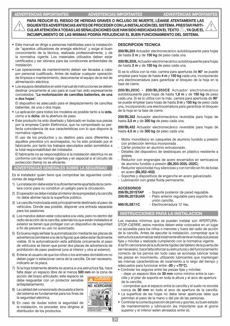
24
• Estemanualsedirigeapersonashabilitadasparalainstalaciónde "aparatos utilizadores de energía eléctrica" y exige el buen conocimiento de la técnica, realizada profesionalmente, y de la normativa vigente. Los materiales utilizados deben estar certificados y ser idóneos para las condiciones ambientales de instalación.
• Lasoperacionesdemantenimientodebenserllevadasacabopor personal cualificado. Antes de realizar cualquier operación de limpieza o mantenimiento, desconectar el equipo de la red de alimentación eléctrica.
•Losequiposdetalladosenestemanualdeinstruccionessedebendestinar únicamente al uso para el cual han sido expresamente concebidos: "La motorización de cancillas batientes, de una o dos hojas".
El dispositivo es adecuado para el desplazamiento de cancillas batientes, de una o dos hojas.
• Laaplicaciónparatodoslosmodelosesposibletantoalaizda. como a la dcha. de la abertura de paso.
• Esteproductohasidodiseñadoyfabricadoentodassuspiezaspor la empresa Cardin Elettronica, que ha comprobado su per-fecta coincidencia de sus características con lo que dispone la normativa vigente.
El uso de los productos y su destino para usos diferentes a aquéllos previstos y/o aconsejados, no ha sido probado por el fabricante, por tanto los trabajos ejecutados están sometidos a la total responsabilidad del instalador.
El fabricante no se responsabiliza si la instalación eléctrica no es conforme con las normas vigentes y en especial si el circuito de protección (tierra) no es eficiente.
Es el instalador quien tiene que comprobar las siguientes condi-ciones de seguridad:1) La instalación debe estar lo suficientemente apartada de la carre-
tera como para no constituir un peligro para la circulación.2) El operador se debe instalar al interior de la propiedad y la cancilla
no debe abrirse hacia la superficie público.3) La cancilla motorizada está principalmente destinado al paso de
vehículos. Donde sea posible, disponer una entrada separada para los peatones.
4) Los mandos deben estar colocados a la vista, pero no dentro del radio de acción de la cancilla; además los que están instalados al exterior se tienen que proteger con un dispositivo de seguridad a fin de prevenir su uso no autorizado.
5) Es buena regla señalar la automatización mediante las placas de advertencia (similares a la de la figura) que debe estar fácilmente visible. Si la automatización está adhibida únicamente al paso de vehículos se tienen que poner dos placas de advertencia de prohibición de paso peatonal (una al interior y otra al exterior).
6) Enterar al usuario de que los niños o los animales domésticos no deben jugar ni estacionar cerca de la cancilla. De ser necesario, indicarlo en la placa.
7) Si la hoja totalmente abierta se acerca a una estructura fija, hace falta dejar un espacio libre de al menos 500 mm en la zona de acción del brazo articulado; este espacio se debe resguardar con un protector sensible antiaplastamiento.
8) La calidad del conexionado de puesta a tierra del sistema es fundamental para los fines de la seguridad eléctrica.
9) En caso de dudas sobre la seguridad de la instalación, no proceder, sino dirigirse al distribuidor de los productos.
DESCRIPCION TECNICA
200/BL203 Actuador electromecánico autobloqueante para hojas de hasta 2 m y de 150 kg de peso cada una.
200/BL203L Actuador electromecánico autobloqueante para hojas de hasta 2 m y de 150 kg de peso cada una.
Si se lo utiliza con la máx. carrera para aperturas de 90° se puede emplear para hojas de hasta 4 m y 150 kg cada una, incorporando una electrocerradura para garantizar el bloqueo de la hoja en la fase de cierre.
200/BL203C - 200/BL203CE Actuador electromecánico autobloqueante para hojas de hasta 1,8 m y de 150 kg de peso cada una. Si se lo utiliza con la máx. carrera para aperturas de 90° se puede emplear para hojas de hasta 3 m y 150 kg de peso cada una, incorporando una electrocerradura para garantizar el bloqueo de la hoja en la fase de cierre.
200/BL352 Actuador electromecánico reversible para hojas de hasta 3,5 m y de 300 kg de peso cada una.
200/BL452 Actuador electromecánico reversible para hojas de hasta 4,5 m y de 300 kg de peso cada una.
- Motor monofásico en casquetes de aluminio fundido a presión con protección térmica incorporada .
- Cárter protector en aluminio extrusionado.- Detalles del dispositivo de desbloqueo en plástico resistente a
golpes.- Reductor con engranajes de acero encerrados en semicascos
de aluminio fundido a presión (BL203-202L-202C).- Reductor epicicloidal muy silencioso y con tornillo sin fin de bolas
en acero (BL352-452).- Soportes y dispositivos de enganche en acero galvanizado.- Lubricación con grasa fluida permanente.
ACCESORIOS206/BL201STAP - Soporte posterior de pared regulable.206/BL201SUAR - Plato anterior regulable para soporte de unión cancilla.980/xLSE11C - Electrocerradura 12 Vac.
Los mandos mínimos que se pueden instalar son APERTURA-STOP-CIERRE; estos mandos deben estar colocados en un lugar no accesible para los niños o menores y fuera del radio de acción de la cancilla. Antes de ejecutar la instalación, comprobar que la estructura a automatizar está totalmente eficiente en todas sus piezas fijas y móviles y realizada cumpliendo con la normativa vigente. A tal fin cerciorarse de la suficiente rigidez del tablero de la puerta (de ser necesario, hace falta reforzar su estructura) y del funcionamiento correcto de los pernos (en todo caso se aconseja lubricar todas las piezas en movimiento, utilizando lubricantes que mantengan las mismas características de rozamiento a lo largo del tiempo y adecuados para funcionar entre -20 y +70°C).•Controlarlossegurosentrelaspiezasfijasymóviles: - dejar un espacio libre de 30 mm como mínimo entre la can-
cilla y el pilar de soporte en toda la altura y el arco de apertura de la cancilla;
- comprobar que el espacio entre la cancilla y el suelo no exceda nunca de 30 mm en todo el arco de apertura de la cancilla.
• La superficie de las hojas no debe tener aperturas tales quepermitan el paso de la mano o del pie de las personas.
• Controlarlacorrectaposicióndepernosygoznes,subuenestadode mantenimiento y lubricación (es importante que el gozne superior y el inferior estén alineados entre sí).
ADVERTENCIAS IMPORTANTES ADVERTENCIAS IMPORTANTES ADVERTENCIAS IMPORTANTESPARA REDUCIR EL RIESGO DE HERIDAS GRAVES O INCLUSO DE MUERTE, LÉANSE ATENTAMENTE LAS SIGUIENTES ADVERTENCIAS ANTES DE PROCEDER CON LA INSTALACIÓN DEL SISTEMA. PRESTAR PARTI-CULAR ATENCIÓN A TODAS LAS SEÑALIZACIONES QUE HAN SIDO INDICADAS EN EL TExTO , YA QUE EL INCUMPLIMIENTO DE LAS MISMAS PODRÍA PERJUDICAR EL BUEN FUNCIONAMIENTO DEL SISTEMA.
ADVERTENCIAS GENERALES SOBRE LA SEGURIDAD
APERTURA AUTOMATICA
NO ACERCARSE
NO DEJAR QUE LOS NIÑOS O ANIMALES DOMESTICOS ESTACIONEN EN EL RADIO DE ACCION DE LA CANCELA
¡CUIDADO!
INSTRUCCIONES PARA LA INSTALACION

25
SCALA: 1:2
Prodotti Technocity
BL352
16-11-98
DI0103 Description :
Product Code :
Date :
Drawing number :
P.J.Heath
CARDIN ELETTRONICA S.p.A - 31020 San Vendemiano (TV) Italy - via Raffaello, 36 Tel: 0438/401818 Fax: 0438/401831
Draft :
All rights reserved. Unauthorised copying or use of the information contained in this document is punishable by law
Scarico condensa BL352/452
A
¡CUIDADO! Instalar siempre los topes mecánicos de la hoja (pos. 1, 2, 3 fig. 11).
• Preverelrecorridodeloscablessegúnlasnecesidadesdeapli-cación de los dispositivos de mando y seguridad cumpliendo con las normas de seguridad vigentes (véase instalación estándar, fig. 1 pág. 2).
•Comprobarquelaautomatizaciónseaadecuadaparaeltamañode la cancilla y la frecuencia de uso (intermitencia de trabajo en pág. 28).
FIJACION DEL DISPOSITIVO 200/BL203- BL203LEl dispositivo se puede fijar tanto a la izquierda como a la derecha de la abertura de paso.La instalación correcta debe respetar el procedimiento indicado.
• Disponerlahojaolashojasenlaposicióndecerrado.• Elegireltipodeinstalación(figs.8y9,pág.5).• Fijarenelpilar(fig.13pág.7)elsoportetrasero,respetandolas
medidas "A" y "B", después de haber comprobado la posición del gozne de la cancilla con respecto al pilar (medida "C" figs. 8 y 9, pág. 5) y en función de la clase de apertura de la hoja que se quiere conseguir.
• Fijarelactuadorpormediodelperno "1" correspondiente en el soporte trasero "5" (fig. 2 en pág. 3) y mediante el perno "7" en el soporte delantero "6".
• Disponerelvástagodelactuadorenextensiónhastaquelleguea 5 mm del final de la carrera.
¡CUIDADO! El eje entre la articulación anterior de enganche soporte anterior "2" y la posterior "1" de enganche soporte pos-terior nunca debe exceder de la medida de 1000 para el BL203 y 1345 para el BL203L (véanse las figuras 8 y 9 en página 5).
• Apoyar en la cancilla el soporte delantero "6", marcando su posición.
Nota: Colocar el operador perfectamente horizontal, usando un nivel de burbuja y fijar el soporte de sujeción anterior (fig. 14 pág. 7).
• Elsoportesetienequefijarenlospuntossiguientes:- en la estructura portante de la cancilla o en la barra transversal
de ésta;- en caso de que esto no fuera posible, es aconsejable fijar en la
cancilla una placa adicional que luego servirá como soporte.• Colocarelactuadorenel soporte "6", introducir el perno "7"
correspondiente y sujetar con los anillos elásticos de seguridad (fig. 2 pág. 3).
• Disponerelcárterprotectorfijandolos4tornillossituadosenelreductor (pos. 2 fig. 2) y fijar el tapón de plástico (pos. 4 fig. 2).
• Siempreconelmotordesbloqueado,abrirlahojahastaeltopemecánico y comprobar que el vástago se halla a unos 5 mm del final de su carrera.
• Encasodequeseutiliceel 200/BL203L para una hoja mayor que 2 m y hasta 4 m, será necesario incorporar una electrocerradura de bloqueo para garantizar el bloqueo de la hoja en fase de cierre.
FIJACION DEL DISPOSITIVO 200/BL352 - 200/BL452El dispositivo se puede fijar tanto a la izquierda como a la derecha de la abertura de paso.La instalación correcta debe respetar el procedimiento indicado.
• Disponerlahojaolashojasenlaposicióndecerrado.• Elegireltipodeinstalación(fig.8,pág.5).• Fijarenelpilar(fig.13pág.7)elsoportetrasero,respetandolas
medidas "A" y "B", después de haber comprobado la posición del gozne de la cancilla con respecto al pilar (medida "C" fig. 8, pág. 5) y en función de la clase de apertura de la hoja que se quiere conseguir.
¡CUIDADO! El motor se tiene que montar en la cancilla con los orificios de descarga de la condensación "A" dispuestos
hacia abajo (ver figura).
• Fijarelactuadorpormediodelperno "1" correspondiente en el soporte trasero "5" (fig. 2 en pág. 3) y mediante el perno "7" en el soporte delantero "6".
• Disponerelvástagodelactuadorenextensiónhastaquelleguea 5 mm del final de la carrera.
¡CUIDADO! El eje entre la articulación anterior de enganche soporte anterior "2" y la posterior "1" de enganche soporte posterior nunca debe exceder de la medida de 1020 para los modelos BL352 y BL452 (véanse la figura 8 en página 5).
• Apoyar en la cancilla el soporte delantero "6", marcando su posición.
Nota: Colocar el operador perfectamente horizontal, usando un nivel de burbuja y fijar el soporte de sujeción anterior (fig. 14 pág. 7).
• Elsoportesetienequefijarenlospuntossiguientes:- en la estructura portante de la cancilla o en la barra transversal
de ésta;- en caso de que esto no fuera posible, es aconsejable fijar en la
cancilla una placa adicional que luego servirá como soporte.• Colocarelactuadorenelsoporte "6", introducir el perno "7"
correspondiente y sujetar con los anillos elásticos de seguridad (fig. 2 pág. 3).
• Disponerelcárterprotectorfijandolos4tornillossituadosenelreductor (pos. 2 fig. 2) y fijar el tapón de plástico (pos. 4 fig. 2).
• Abrirlahojahastaeltopemécanicoycomprobarqueelvástagose halla a unos 5 mm del final de su carrera.
• Incorporar laelectrocerraduraparagarantizarelbloqueodelahoja.
FIJACION DEL DISPOSITIVO 200/BL203C - 200/BL203CEEl dispositivo se puede fijar tanto a la izquierda como a la derecha de la abertura de paso.
• Disponerlahojaolashojasenlaposicióndecerrado.• Elegireltipodeinstalación(fig.10,pág.5).• Fijarenelpilar(fig.13pág.7)elsoportetrasero,respetandolas
medidas "A" y "B", después de haber comprobado la posición del gozne de la cancilla con respecto al pilar (medida "C" fig. 10, pág. 5) y en función de la clase de apertura de la hoja que se quiere conseguir.
Nota: en caso de preinstalación de los soportes (trasero y delan-tero) sin la presencia del pistón, consultar también las indicaciones que se encuentran en la figura 18.
• Disponerelcárterprotector "3" (con la parte estriada dispuesta hacia la cancilla) fijando los 4 tornillos "2" ubicados en el reductor (apretar a fondo) y fijar el tapón de plástico "5" por medio de los 4 tornillos suministrados (fig. 2 pág. 3).
• Hacertrasladarlacaracoladelactuador(det.4fig.3)hastallegara 15 mm desde el final de la carrera de cierre.
• Fijarpormediodelperno "1" correspondiente el actuador en el soporte trasero "6" (fig. 3 pág. 3).
• Disponerelactuadorenlaposicióncorrientedefuncionamientoapoyando en la cancilla el soporte anterior, marcando luego su posición.
Nota: Colocar el operador perfectamente horizontal, usando un nivel de burbuja.
• Fijarelsoportedesujeciónanterior(fig.14pág.7).• Elsoportesetienequefijarenlospuntossiguientes:- en la estructura portante de la cancilla o en la barra transversal
de ésta;- en caso de que esto no fuera posible, es aconsejable fijar en la
cancilla una placa adicional que luego servirá como soporte.•Introducirelpernodelacaracola"4" en el orificio correspondiente
del soporte "9" y bloquear por medio del tornillo "8" (fig. 3 pág. 3).• Desbloquearelactuadorydisponer lahojaenapertura, luego
comprobar el funcionamiento correcto de todos los elementos.• Encasodequeseutiliceel 200/BL203C - 200/BL203CE para
una hoja mayor que 1,8 m y hasta 3 m, será necesario incorporar una electrocerradura de bloqueo para garantizar el bloqueo de la hoja en fase de cierre.
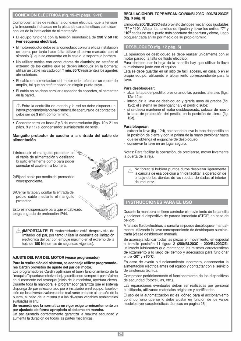
26
SCALA: 1:2
Prodotti Technocity
BL202
01-07-99
DI0131 Description :
Product Code :
Date :
Drawing number :
P.J.Heath
CARDIN ELETTRONICA S.p.A - 31020 San Vendemiano (TV) Italy - via Raffaello, 36 Tel: 0438/401818 Fax: 0438/401831
Draft :
All rights reserved. Unauthorised copying or use of the information contained in this document is punishable by law
Collegamento gommino protezione
12
31
23
12
3
Comprobar, antes de realizar la conexión eléctrica, que la tensión y la frecuencia indicadas en la placa de características coincidan con las de la instalación de alimentación.
• Elequipofuncionaconlatensiónmonofásicade230 V 50 Hz (ver esquema eléctrico).
• Elmotorreductordebeestarconectadoconunaeficazinstalaciónde tierra, por tanto hace falta utilizar el borne marcado con el símbolo que se encuentra en la caja que soporta la bornera.
• Noutilizarcablesconconductoresdealuminio;noestañarelextremo de los cables que se deben introducir en la bornera; utilizar un cable marcado con T mín. 85°C resistente a los agentes atmosféricos.
• Elcabledealimentacióndelmotordebeefectuarunrecorridoamplio, tal que no esté tensado en ningún punto suyo.
• Elcablenosedebeenrollaralrededordesoportes,nicementaren la pared.
Entre la centralita de mando y la red se debe disponer un interruptor omnipolar cuya distancia de apertura de los contactos debe ser de 3 mm como mínimo.
• Conectarentrelasfases2y3delmotorreductor(figs.19y21enpágs. 9 y 11) el condensador suministrado de serie.
Manguito protector de caucho a la entrada del cable de alimentación
1) Introducir el manguito protector en el cable de alimentación y deslizarlo lo suficientemente como para poder conectar el cable en la bornera.
2) Fijar el cable por medio del prensahilo correspondiente.
3) Cerrar la tapa y ocultar la entrada del propio cable mediante el manguito protector.
Esto es indispensable para que el cableado tenga el grado de protección IP44.
¡IMPORTANTE! El motorreductor está desprovisto de limitador del par, por tanto utilizar la centralita de limitación electrónica del par con empuje máximo en el extremo de la hoja de 150 N (normas de seguridad vigentes).
AJUSTE DEL PAR DEL MOTOR (véase programador)Para la realización del sistema, se aconseja utilizar programado-res Cardin provistos de ajuste del par del motor.Los programadores Cardin optimizan el buen funcionamiento de la “máquina” (puertas motorizadas), garantizando siempre el par máximo en el momento del arranque (inicio de la maniobra, apertura-cierre). Durante toda la maniobra, el programador garantiza que el sistema disponga del par seleccionado por el instalador en el equipo; la selec-ción de los diversos valores debe realizarse en base al tamaño de la puerta, al peso de la misma y a las diversas variables ambientales evaluadas in situ.Se recuerda que la normativa en vigor exige terminantemente un par ajustado de forma apropiada al sistema en marcha. Un par ajustado correctamente garantiza la máxima seguridad y aumenta la duración de todas las partes mecánicas.
REGULACION DEL TOPE MECANICO 200/BL203C - 200/BL203CE (fig. 3 pág. 3)
El modelo 200/BL203C está provisto de topes mecánicos ajustables "7" y "10". Aflojar los tornillos de fijación y llevar los anillos "7" y "10" cada uno en el punto más oportuno de apertura y cierre, luego bloquear cada anillo por medio de su propio tornillo.
La operación de desbloqueo se debe realizar únicamente con el motor parado, a falta de fluido eléctrico.Para desbloquear la hoja de la cancilla hay que utilizar la llave suministrada junto con el equipo. Esta se debe guardar en un sitio de fácil acceso, en casa, o en el propio equipo, utilizando el alojamiento correspondiente para la llave.
Para desbloquear:- alzar la tapa del pestillo, presionando las paredes laterales (figs.
12a-12b);- introducir la llave de desbloqueo y girarla unos 30 grados (fig.
12c); el sistema se desengancha y el pestillo sube;- si se desea mantener el motor desbloqueado, colocar de nuevo
la tapa de protección del pestillo en la posición de cierre (fig. 12e).
Para bloquear:- extraer la llave (fig. 12d), colocar de nuevo la tapa del pestillo en
la posición de cierre y con la palma de la mano presionar hasta que se obtenga el enganche de desbloqueo;
- conservar la llave en un lugar seguro.
Notas: Para facilitar la operación, de precisarse, mover levemente la puerta de la reja.
No forzar, si hubiera puntos duros desplazar ligeramente la cancilla de esa posición a fin de facilitar la operación de encaje de los dientes de las ruedas dentadas al interior del reductor.
Durante la maniobra se tiene controlar el movimiento de la cancilla y accionar el dispositivo de parada inmediata (STOP) en caso de peligro.A falta de fluido eléctrico, la cancilla se puede desbloquear manual-mente utilizando la llave correspondiente de desbloqueo suminis-trada (véase desbloqueo manual).Se aconseja lubricar todas las piezas en movimiento, en especial el tornillo posición 11 figura 3 (200/BL203C - 200/BL203CE), utilizando lubricantes que mantengan las mismas características de rozamiento a lo largo del tiempo y adecuados para funcionar entre -20° y +70°C. En caso de avería o funcionamiento incorrecto, desconectar la alimentación eléctrica antes del equipo y contactar con el servicio de asistencia técnica.Comprobar periódicamente el funcionamiento de los dispositivos de seguridad (fotocélulas, etc.).Las reparaciones eventuales deben ser realizadas por personal cualificado, utilizando materiales originales y certificados.El uso de la automatización no es idóneo para el accionamiento continuo, sino que se lo debe ajustar en función de los varios modelos (ver características técnicas en página 28).
CONExIÓN ELÉCTRICA (fig. 19-21 págs. 9-11)
DESBLOQUEO (fig. 12 pág. 6)
INSTRUCCIONES PARA EL USO
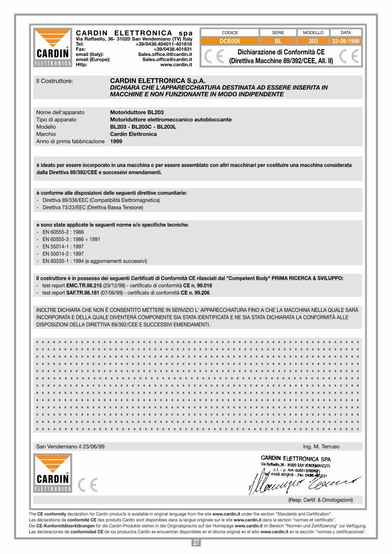
27
CARDIN ELETTRONICA spa Via Raffaello, 36- 31020 San Vendemiano (TV) ItalyTel: +39/0438.404011-401818Fax: +39/0438.401831email (Italy): [email protected] (Europe): [email protected]: www.cardin.it
BL 203 23-06-1999DCE005
Il Costruttore: CARDIN ELETTRONICA S.p.A. DICHIARA CHE L'APPARECCHIATURA DESTINATA AD ESSERE INSERITA IN MACCHINE E NON FUNZIONANTE IN MODO INDIPENDENTE
Nome dell'apparato Motoriduttore BL203Tipo di apparato Motoriduttore elettromeccanico autobloccanteModello BL203 - BL203C - BL203LMarchio Cardin ElettronicaAnno di prima fabbricazione 1999
e sono state applicate le seguenti norme e/o specifiche tecniche:- EN 60555-2 : 1986- EN 60555-3 : 1986 + 1991- EN 55014-1 : 1997- EN 55014-2 : 1997- EN 60335-1 : 1994 (e aggiornamenti successivi)
è ideato per essere incorporato in una macchina o per essere assemblato con altri macchinari per costituire una macchina considerata dalla Direttiva 89/392/CEE e successivi emendamenti.
è conforme alle disposizioni delle seguenti direttive comunitarie:- Direttiva 89/336/EEC (Compatibilità Elettromagnetica)- Direttiva 73/23/EEC (Direttiva Bassa Tensione)
San Vendemiano il 23/06/99 Ing. M. Terruso
(Resp. Certif. & Omologazioni)
x x x x x x x x x x x x x x x x x x x x x x x x x x x x x x x x x x x x x x x x x x x x x x x x x x x x x x x x x x
x x x x x x x x x x x x x x x x x x x x x x x x x x x x x x x x x x x x x x x x x x x x x x x x x x x x x x x x x x
x x x x x x x x x x x x x x x x x x x x x x x x x x x x x x x x x x x x x x x x x x x x x x x x x x x x x x x x x x
x x x x x x x x x x x x x x x x x x x x x x x x x x x x x x x x x x x x x x x x x x x x x x x x x x x x x x x x x x
x x x x x x x x x x x x x x x x x x x x x x x x x x x x x x x x x x x x x x x x x x x x x x x x x x x x x x x x x x
x x x x x x x x x x x x x x x x x x x x x x x x x x x x x x x x x x x x x x x x x x x x x x x x x x x x x x x x x
x x x x x x x x x x x x x x x x x x x x x x x x x x x x x x x x x x x x x x x x x x x x x x x x x x x x x x x x x x
x x x x x x x x x x x x x x x x x x x x x x x x x x x x x x x x x x x x x x x x x x x x x x x x x x x x x x x x x x
x x x x x x x x x x x x x x x x x x x x x x x x x x x x x x x x x x x x x x x x x x x x x x x x x x x x x x x x x x
x x x x x x x x x x x x x x x x x x x x x x x x x x x x x x x x x x x x x x x x x x x x x x x x x x x x x x x x x x
x x x x x x x x x x x x x x x x x x x x x x x x x x x x x x x x x x x x x x x x x x x x x x x x x x x x x x x x x x
x x x x x x x x x x x x x x x x x x x x x x x x x x x x x x x x x x x x x x x x x x x x x x x x x x x x x x x x x x
x x x x x x x x x x x x x x x x x x x x x x x x x x x x x x x x x x x x x x x x x x x x x x x x x x x x x x x x x
Dichiarazione di Conformità CE(Direttiva Macchine 89/392/CEE, All. II)
MODELLO DATACODICE SERIE
Il costruttore è in possesso dei seguenti Certificati di Conformità CE rilasciati dal "Competent Body" PRIMA RICERCA & SVILUPPO:- test report EMC.TR.98.215 (29/12/98) - certificato di conformità CE n. 99.018- test report SAF.TR.98.181 (07/06/99) - certificato di conformità CE n. 99.206
INOLTRE DICHIARA CHE NON È CONSENTITO METTERE IN SERVIZIO L' APPARECCHIATURA FINO A CHE LA MACCHINA NELLA QUALE SARÀ INCORPORATA E DELLA QUALE DIVENTERÀ COMPONENTE SIA STATA IDENTIFICATA E NE SIA STATA DICHIARATA LA CONFORMITÀ ALLE DISPOSIZIONI DELLA DIRETTIVA 89/392/CEE E SUCCESSIVI EMENDAMENTI.
The CE conformity declaration for Cardin products is available in original language from the site www.cardin.it under the section "Standards and Certification".Les déclarations de conformité CE des produits Cardin sont disponibles dans la langue originale sur le site www.cardin.it dans la section "normes et certificats".Die CE-konformitätserklärungen für die Cardin-Produkte stehen in der Originalsprache auf der Homepage www.cardin.it im Bereich "Normen und Zertifizierung" zur Verfügung.Las declaraciones de conformidad CE de los productos Cardin se encuentran disponibles en el idioma original en el sitio www.cardin.it en la sección "normas y certificaciones".
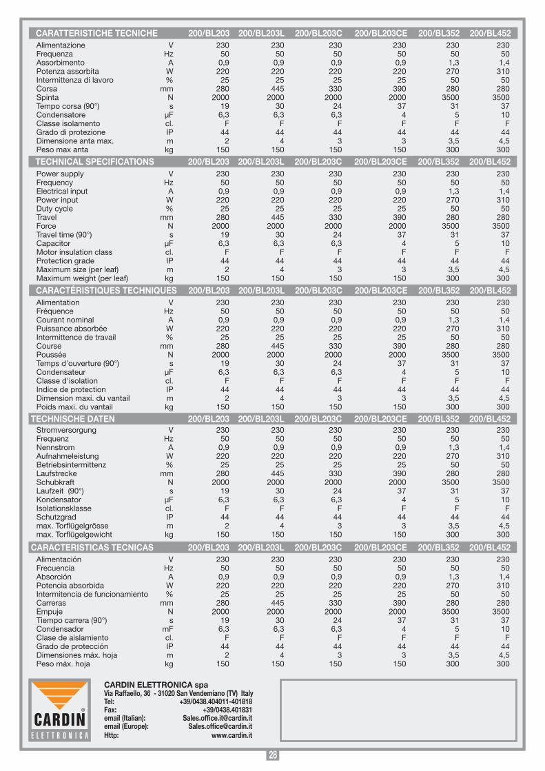
28
CARDIN ELETTRONICA spa Via Raffaello, 36 - 31020 San Vendemiano (TV) ItalyTel: +39/0438.404011-401818Fax: +39/0438.401831email (Italian): [email protected] (Europe): [email protected]: www.cardin.it
TECHNICAL SPECIFICATIONS 200/BL203 200/BL203L 200/BL203C 200/BL203CE 200/BL352 200/BL452
CARACTÉRISTIQUES TECHNIQUES 200/BL203 200/BL203L 200/BL203C 200/BL203CE 200/BL352 200/BL452
TECHNISCHE DATEN 200/BL203 200/BL203L 200/BL203C 200/BL203CE 200/BL352 200/BL452
CARACTERISTICAS TECNICAS 200/BL203 200/BL203L 200/BL203C 200/BL203CE 200/BL352 200/BL452
CARATTERISTICHE TECNICHE 200/BL203 200/BL203L 200/BL203C 200/BL203CE 200/BL352 200/BL452
Alimentación V 230 230 230 230 230 230 Frecuencia Hz 50 50 50 50 50 50 Absorción A 0,9 0,9 0,9 0,9 1,3 1,4 Potencia absorbida W 220 220 220 220 270 310 Intermitencia de funcionamiento % 25 25 25 25 50 50 Carreras mm 280 445 330 390 280 280 Empuje N 2000 2000 2000 2000 3500 3500 Tiempo carrera (90°) s 19 30 24 37 31 37 Condensador mF 6,3 6,3 6,3 4 5 10 Clase de aislamiento cl. F F F F F F Grado de protección IP 44 44 44 44 44 44 Dimensiones máx. hoja m 2 4 3 3 3,5 4,5 Peso máx. hoja kg 150 150 150 150 300 300
Alimentazione V 230 230 230 230 230 230 Frequenza Hz 50 50 50 50 50 50 Assorbimento A 0,9 0,9 0,9 0,9 1,3 1,4 Potenza assorbita W 220 220 220 220 270 310 Intermittenza di lavoro % 25 25 25 25 50 50 Corsa mm 280 445 330 390 280 280 Spinta N 2000 2000 2000 2000 3500 3500 Tempo corsa (90°) s 19 30 24 37 31 37 Condensatore µF 6,3 6,3 6,3 4 5 10 Classe isolamento cl. F F F F F F Grado di protezione IP 44 44 44 44 44 44 Dimensione anta max. m 2 4 3 3 3,5 4,5 Peso max anta kg 150 150 150 150 300 300
Power supply V 230 230 230 230 230 230 Frequency Hz 50 50 50 50 50 50 Electrical input A 0,9 0,9 0,9 0,9 1,3 1,4 Power input W 220 220 220 220 270 310 Duty cycle % 25 25 25 25 50 50 Travel mm 280 445 330 390 280 280 Force N 2000 2000 2000 2000 3500 3500 Travel time (90°) s 19 30 24 37 31 37 Capacitor µF 6,3 6,3 6,3 4 5 10 Motor insulation class cl. F F F F F F Protection grade IP 44 44 44 44 44 44 Maximum size (per leaf) m 2 4 3 3 3,5 4,5 Maximum weight (per leaf) kg 150 150 150 150 300 300
Alimentation V 230 230 230 230 230 230 Fréquence Hz 50 50 50 50 50 50 Courant nominal A 0,9 0,9 0,9 0,9 1,3 1,4 Puissance absorbée W 220 220 220 220 270 310 Intermittence de travail % 25 25 25 25 50 50 Course mm 280 445 330 390 280 280 Poussée N 2000 2000 2000 2000 3500 3500 Temps d'ouverture (90°) s 19 30 24 37 31 37 Condensateur µF 6,3 6,3 6,3 4 5 10 Classe d'isolation cl. F F F F F F Indice de protection IP 44 44 44 44 44 44 Dimension maxi. du vantail m 2 4 3 3 3,5 4,5 Poids maxi. du vantail kg 150 150 150 150 300 300
Stromversorgung V 230 230 230 230 230 230 Frequenz Hz 50 50 50 50 50 50 Nennstrom A 0,9 0,9 0,9 0,9 1,3 1,4 Aufnahmeleistung W 220 220 220 220 270 310 Betriebsintermittenz % 25 25 25 25 50 50 Laufstrecke mm 280 445 330 390 280 280 Schubkraft N 2000 2000 2000 2000 3500 3500 Laufzeit (90°) s 19 30 24 37 31 37 Kondensator µF 6,3 6,3 6,3 4 5 10 Isolationsklasse cl. F F F F F F Schutzgrad IP 44 44 44 44 44 44 max. Torflügelgrösse m 2 4 3 3 3,5 4,5 max. Torflügelgewicht kg 150 150 150 150 300 300