card specification v2.0, sdio specification v2.0 and ce...
TRANSCRIPT

AT91SAMARM-basedEmbedded MPU
Application Note
11126A–ATARM–04-Nov-11
HSMCI on SAM9G15/G25/G35/X25/X35Microcontrollers
1. IntroductionSAM9G15/G25/G35/X25/X35 offer a High Speed Multimedia Speed Card Interface(HSMCI), which supports MultiMedia Card (MMC) Specification V4.3, SD MemoryCard Specification V2.0, SDIO Specification V2.0 and CE-ATA V1.1.
This document focuses on how to use the HSMCI to access an SD/MMC memorycard and help users to get familiar with the HSMCI.

2. References• SAM9G15/G25/G35/X25/X35 Datasheet
• MULTIMEDIACARD (MMC) ELECTRICAL STANDARD, HIGH CAPACITY (MMCA, 4.3)
• SD Specification Part 1 Physical Layer Simplified Specification Ver2.00
• SDIO Simplified Specification Ver2.00
3. SD/MMC Card Basics
3.1 SD/MMC Card Diagram
Figure 3-1. SD/MMC Card Diagram
3.2 SD/MMC Card PinsBoth SD memory card and MultiMedia card have one clock pin (CLK), one command pin (CMD),several data pins (DAT) and supply pins (VDD & VSS).
For more details on the definition of each pin and on how to connect a card with HSMCI, refer toSection 4.2 ”SD/MMC Bus Connection”.
3.3 SD/MMC BusCommunication over the SD/MMC bus is based on command and data bit streams that are initi-ated by a start bit and terminated by a stop bit.
• Command: a command is a token that starts an operation. A command is sent from the hosteither to a single card (addressed command) or to all connected cards (broadcastcommand). A command is transferred serially on the CMD line.
• Response: a response is a token that is sent from an addressed card, or (synchronously)from all connected cards, to the host as an answer to a previously received command. Aresponse is transferred serially on the CMD line.
• Data: data can be transferred from the card to the host or vice versa. Data is transferred viathe data lines.
During access to MMC cards, HSMCI can generate a continuous data stream, which can be ter-minated only when a stop command follows on the CMD line. Use data stream mode, and theoverhead can be reduced to an absolute minimum.
211126A–ATARM–04-Nov-11
Application Note

Application Note
4. High Speed MultiMedia Card Interface of SAM9G15/G25/G35/X25/X35Microcontrollers
4.1 DescriptionThe HSMCI includes a command register, response registers, data registers, timeout countersand error detection logic that automatically handle the transmission of commands and, whenrequired, the reception of the associated responses and data with a limited processor overhead.
The HSMCI supports stream, block and multi block data read and write, and is compatible withthe DMA Controller (DMAC), minimizing processor intervention for large buffer transfers.
The HSMCI contains the embedded characteristics below, which are related to SD/MMC cards.
• Compatible with MMC Plus Specification Version 4.3
• Compatible with MultiMedia Plus Specification Version 4.3
• Compatible with SD Memory Card Specification Version 2.0
• Compatible with SDIO Card Specification Version 2.0
4.2 SD/MMC Bus ConnectionThe SD memory card bus includes 9 pins, as listed in Table 4-1.
The MMC card bus includes 13 pins, as listed in Table 4-2.
The HSMCI has 6 pins including one Command/Response pin (MCCDA), one Clock pin (MCCK)and four data pins (MCDA0, MCDA1 MCDA2 and MCDA3).
Pin Number Name Description1 CD/DAT[3] Card detect/Data line Bit 32 CMD Command/Response3 VSS1 Supply voltage ground4 VDD Supply voltage5 CLK Clock6 VSS2 Supply voltage ground7 DAT[0] Data line Bit 08 DAT[1] Data line Bit 19 DAT[2] Data line Bit 2
Pin Number Name Description1 DAT[3] Data line Bit 32 CMD Command/Response3 VSS1 Supply voltage ground4 VDD Supply voltage5 CLK Clock6 VSS2 Supply voltage ground7 DAT[0] Data line Bit 08 DAT[1] Data line Bit 19 DAT[2] Data line Bit 210 DAT[4] Data line Bit 411 DAT[5] Data line Bit 512 DAT[6] Data line Bit 613 DAT[7] Data line Bit 7
311126A–ATARM–04-Nov-11

Tab le 4-3 shows how to connec t HSMCI w i th an SD/MMC card onSAM9G15/G25/G35/X25/X35.
Figure 4-1. SD Memory Card Bus Connection
PinNumber
MMC CardPin Name
SD MemoryCard PinName
HSMCI Pin NameonSAM9G15/G25/G35/X25/X35
HSMCI0Signal
HSMCI0 IOPeripheral
HSMCI1Signal
HSMCI1 IOPeripheral
1 DAT[3] CD/DAT[3] MCDA3 MCI0_DA3 PA20.A MCI1_DA3 PA4.B2 CMD CMD MCCDA MCI0_CDA PA16.A MCI1_CDA PA12.B3 VSS1 VSS1 VSS N.G. N.G. N.G. N.G.4 VDD VDD VDD N.G. N.G. N.G. N.G.5 CLK CLK MCCK MCI0_CK PA17.A MCI1_CK PA13.B6 VSS2 VSS2 VSS N.G. N.G. N.G. N.G.7 DAT[0] DAT[0] MCDA0 MCI0_DA0 PA15.A MCI1_DA0 PA11.B8 DAT[1] DAT[1] MCDA1 MCI0_DA1 PA18.A MCI1_DA1 PA2.B9 DAT[2] DAT[2] MCDA2 MCI0_DA2 PA19.A MCI1_DA2 PA3.B10 DAT[4] N.G. N.C. N.G. N.G. N.G. N.G.11 DAT[5] N.G. N.C. N.G. N.G. N.G. N.G.12 DAT[6] N.G. N.C. N.G. N.G. N.G. N.G.13 DAT[7] N.G. N.C. N.G. N.G. N.G. N.G.
411126A–ATARM–04-Nov-11
Application Note

Application Note
Figure 4-2. MMC Bus Connection
Figure 4-3. Example Circuit
4.3 HSMCI UsageThis section involves some HSMCI user interfaces. For details about these user interfaces, referto the SAM9G15/G25/G35/X25/X35 datasheet.
4.3.1 HSMCI Clock & High-speed ModeThe HSMCI clock is obtained from the Master Clock (MCK) divided by (2*(CLKDIV+1)). CLKDIVvalue can be set in the HSMCI Mode Register (HSMCI_MR). I t generates com-mand/data/response clock for access to SD/MMC cards.
The HSMCI clock may be changed during communication with the SD/MMC card:
• On initialization, the HSMCI clock is usually set to 400 KHz so that all SD/MMC devices canbe accepted.
511126A–ATARM–04-Nov-11

• After the card has been identified and selected, the HSMCI clock can be increased to allow ahigher data rate. As defined in the specification, the maximized SD clock is about 25 MHz(normal mode) or 50 MHz (high-speed mode).
Note: Since the HSMCI clock is generated from MCK, the source clock, MCK should be consideredcarefully to maximize the MCI transfer rate.
For information on the SD/MMC clock, high-speed mode and mode switching, refer to theSD/MMC specifications.
4.3.2 HSMCI Bus WidthHSMCI can use more than one data line to transfer data with the SD/MMC card. This bus widthis controlled by a field called SDCBUS in the HSMCI SDCard/SDIO Register (HSMCI_SDCR). Itmust be the same as the actual bus width that the card is using.
• On initialization, the bus width should be reset to 1-bit mode, the default configuration. In thiscase, only DAT[0] is used to transfer data.
In 1-bit mode, the pins are used as inTable 4-4:
• After the card is initialized, the host can identify the bus width that the SD/MMC cardsupports.
• After the card is switched to the bus width it supports (usually 4-bit mode),HSMCI_SDCR.SDCBUS must be set to the corresponding value too.
In 4-bit mode (HSMCI_SDCR.SDCBUS is set to 4-bit width), the pins are used as in Table 4-5:
• Then data can be transferred with the new bus width.
For information on how to identify the supported bus width of the SD/MMC cards and how toswitch the bus width of the cards, refer to the SD/MMC bus width definition and switching on theSD/MMC specifications.
4.3.3 HSMCI Command/ResponseThrough HSMCI Argument Register (HSMCI_ARGR), HSMCI Command Register(HSMCI_CMDR) and HSMCI Response Register (HSMCI_RSPR), the SD/MMC commands andarguments are carried out and responses are brought back.
To send command and get response, register operations are as follows:
Pin on Card Pin on HSMCI Used or NotCLK MCCK UsedCMD MCCD UsedDAT[0] MCDA0 UsedDAT[1] MCDA1 Not UsedDAT[2] MCDA2 Not UsedDAT[3] MCDA3 Not Used
Pin on Card Pin on HSMCI Used or NotCLK MCCD UsedCMD MCCK UsedDAT0 MCDA0 UsedDAT1 MCDA1 UsedDAT2 MCDA2 UsedDAT3 MCDA3 Used
611126A–ATARM–04-Nov-11
Application Note

Application Note
• If there is an argument, fill it in HSMCI_ARGR
• Fill HSMCI_CMDR with the right value:
– Set CMDNB to the expected command index (e.g. 0 for CMD0)
– Set RSPTYP to the expected response type (number of bits in response)
– Select the right command options in SPCMD and OPCMD, if necessary
– Use TRCMD to indicate if there is a data transfer followed or stopped, TRDIR toselect the data transfer direction, and TRTYP to define the type of transfer (e.g.single block or multiple blocks transfer).
– IOSPCMD is specified for SDIO special commands, which here must be 0.
• Once the HSMCI_CMDR is filled, the expected command is clocked out immediately.
• After CMDRDY in HSMCI Status Register (HSMCI_SR) is set, response data can be readfrom HSMCI_RSPR if there is any response.
4.3.4 HSMCI Data Block TransferIf HSMCI_CMDR.TRCMD indicates there is data to transfer, data blocks are transferred on theHSMCI data bus.
The data length of the transfer is described in the HSMCI Block Register (HSMCI_BLKR), asBlock Length (BLKLEN) and Block Count (BCNT). If the Block Count is set to zero and the com-mand is a multiple block transfer (read or write), the data line(s) is(are) ready for any size ofdata.
• CMDx with data:
– Set HSMCI_BLKR to define the data transfer
– Set other settings according to the command
– Set HSMCI_CMDR with TRCMD=01 (start data transfer)
– Start the data transfer by reading/writing HSMCI Receive Data Register(HSMCI_RDR) / HSMCI Transmit Data Register (HSMCI_TDR) or use the DMAcontroller to do these operations
• No command, data transfer for continuous R/W, after a multiple read/write command withoutblock number definition:
– Set HSMCI_BLKR to define the data transfer
– Start the data transfer by reading/writing HSMCI Receive Data Register(HSMCI_RDR) / HSMCI Transmit Data Register (HSMCI_TDR) or use the DMAcontroller to do these operations
• Stop data transfer
– Write the stop command index to HSMCI_CMDR.CMDNB and set TRCMD=10 (stopdata transfer)
For more details on HSMCI data block transfer, refer to Section 5.1.2 ”Send SD/MMC Com-mands with DATA” and Section 5.1.3 ”DMA Data Transfer Setup”.
4.3.5 Read/Write ProofThis feature stops the HSMCI clock during a read or write access, if the internal FIFO is full orempty.
711126A–ATARM–04-Nov-11
The two bits, RDPROOF and WRPROOF in the HSMCI Mode Register (HSMCI_MR) allow tostop the HSMCI Clock during a read or write access, if the internal FIFO is full or empty. This isuseful when processing continuous read/write, so that no data is lost.
4.3.6 Data Transfer with DMASAM9G15/G25/G35/X25/X35 microcontrollers have a DMA controller, which is an AHB-centralDMA controller that transfers data from a source peripheral to a destination peripheral over oneor more AMBA buses. It is used for high-speed peripherals to reduce the CPU workload.
SAM9G15/G25/G35/X25/X35 microcontrollers enable DMA support on HSMCI by setting theDMAEN bit in the HSMCI DMA Configuration Register (HSMCI_DMA).
For more details on data transfer with DMA, refer to Section 5.1.3 ”DMA Data Transfer Setup”,and to the DMA Controller section and the High Speed MultiMedia Card Interface section inSAM9G15, SAM9G25, SAM9G35, SAM9X25 and SAM9X35 datasheets.
5. Software ExamplesThis section briefly introduces how the APIs in mcid_dma.c implement low-level SD/MMC com-mand/response/data operations and how the APIs in sdmmc.c implement a complete SD/MMCcommand.
Bo th mc id_dma.c and sdmmc.c can be found in the SD/MMC l ib ra ry o fSAM9G15/G25/G35/X25/X35 software package. Refer to the package for details.
5.1 SD/MMC CommandsThe MCID_SendCmd() is used to send SD/MMC commands via the HSMCI. This API needs twoparameters: a pointer to a sMcid, the type of which is a structure of MCI driver, and a pointer toan sSdmmcCommand, the type of which is a structure of SD/MMC command instance. ThesSdmmcCommand structure contains an uSdmmcCmdOp-type union called cmdOp. Differentvalues set in the cmdOp cause different configurations of the HSMCI user interface.
According to the cmdOp value, there are two types of commands: normal commands and datatransfer commands. Sect ion 5.1.1 ”Send SD/MMC Commands” descr ibes howMCID_SendCmd() sends a normal command. Section 5.1.2 ”Send SD/MMC Commands withDATA” describes how MCID_SendCmd() sends a data transfer command.
The definitions of the structures and the union can be found in SD/MMC library ofSAM9G15/G25/G35/X25/X35 software package. Refer to the package for more details.
The rest of Section 5.1 ”SD/MMC Commands” describes how to transfer data by using theHSMCI DMA user interface.
5.1.1 Send SD/MMC CommandsBefore a command is issued, MCID_SendCmd() first checks if the previous command has beencompleted.
if (!MCID_IsCmdCompleted(pMcid)){
return SDMMC_ERROR_BUSY;}
If the previous command has been completed, the next command can be issued. The TransferDone Interrupt and all response-related interrupts should be enabled to handle:
811126A–ATARM–04-Nov-11
Application Note
Application Note
• when the command is sent,
• when the response is received,
• if any error occurs.
ier = HSMCI_IER_XFRDONE | STATUS_ERRORS_RESP;
The ier variable is used to set the corresponding bits in the HSMCI Interrupt Enable Register,which controls the source of all interrupts requested by HSMCI.
To wait for the response from card, the latency from command to response can be selected byHSMCI.
if (pCmd->cmdOp.bmBits.sendCmd){
cmdr |= HSMCI_CMDR_MAXLAT;}
The cmdr variable is used to configure the HSMCI Command Register (HSMCI_CMDR), whichcontains the command index, response type and other command-related opinions.
According to the SD/MMC specification, some responses from card are not appended with CRCcode like others, so the CRC error should be ignored by HSMCI.
Also, the length of response from card can be 48 bits or 136 bits, or for some commands, noresponse will be returned by card. In this case, the HSMCI Command Register and the HSMCIInterrupt Enable Register should be configured in the correct way.
switch(pCmd->cmdOp.bmBits.respType){
case 3: case 4:/* ignore CRC error */
ier &= ~(uint32_t)HSMCI_IER_RCRCE;case 1: case 5: case 6: case 7:
cmdr |= HSMCI_CMDR_RSPTYP_48_BIT;break;
case 2:cmdr |= HSMCI_CMDR_RSPTYP_136_BIT;break;
/* No response, ignore RTOE */default:
ier &= ~(uint32_t)HSMCI_IER_RTOE;}
As mentioned in Section 4.3.3 ”HSMCI Command/Response”, the expected command will beclocked out immediately after the HSMCI_CMDR is filled. So the argument of the commandshould be written into the HSMCI Argument Register (HSMCI_ARGR) first.
pHw->HSMCI_ARGR = pCmd->dwArg;
dwArg, one of the elements of the sSdmmcCommand, contains the argument of the expectedcommand pCmd.
Then the HSMCI_CMDR can be filled to send the command via MCCD of HSMCI.
pHw->HSMCI_CMDR = cmdr;
And the necessary interrupts can be enabled for the HSMCI.
HSMCI_EnableIt(pHw, ier);
If no error occurs, after the interrupt, the response of the command is copied in ISR, and can beread from the response buffer ( i f al located), pResp, one of the elements of thesSdmmcCommand.
911126A–ATARM–04-Nov-11

5.1.2 Send SD/MMC Commands with DATAAs for sending a normal SD/MMC command, make sure that the previous command has beencompleted before sending a data transfer command. Besides, check the NOTBUSY bit andDTIP (Data Transfer in Progress) bit in the HSMCI Status Register (HSMCI_SR) if the previousdata transfer has been completed.
volatile uint32_t busyWait = 0x0001000;while(busyWait --){
uint32_t sr = HSMCI_GetStatus(pHw);if ((sr & HSMCI_SR_NOTBUSY) && ((sr & HSMCI_SR_DTIP) == 0)){
break;}
}
5.1.2.1 Fixed Data LengthSince the length of data to be transferred is fixed, the block length and the block count of datashould be written into the HSMCI Block Register (HSMCI_BLKR).
HSMCI_ConfigureTransfer(pHw, pCmd->wBlockSize, pCmd->wNbBlocks);
wBlockSize is the block length and wNbBlocks is the block count. Both of them are the elementsof the data transfer command, pCmd, an sSdmmcCommand-type pointer.
To prevent from losing any data during the transfer, the WRPROOF bit and the RDPROOF bit inthe MSMCI Mode Register (HSMCI_MR) can be set.
HSMCI_ConfigureMode(pHw, mr | HSMCI_MR_WRPROOF| HSMCI_MR_RDPROOF| (pCmd->wBlockSize << 16));
For more information on the WRPROOF bit and the RDPROOF bit, refer to Section 4.3.5”Read/Write Proof”.
In HSMCI_CMDR, the transfer type and direction should be configured before the command isissued.
For write commands:
cmdr |= (pCmd->wNbBlocks == 1) ?_CMDR_SDMEM_SINGLE :_CMDR_SDMEM_MULTI;
For read commands:
cmdr |= HSMCI_CMDR_TRDIR_READ| ((pCmd->wNbBlocks == 1) ? _CMDR_SDMEM_SINGLE : _CMDR_SDMEM_MULTI);
If it is a single block data transfer command, the transfer type should be set as SINGLE inHSMCI_CMDR. If it is a multiple block transfer command, the transfer type should be set asMUTIPLE. Also, the TRCMD field in HSMCI_CMDR should be set as START_DATA for startingdata transfer.
The fixed data length should be set up before issuing a command. This operation can be doneby the DMA controller. Refer to Section 5.1.3 ”DMA Data Transfer Setup”.
Now cmdr can be written into HSMCI_CMDR to clock out the data transfer command. If it is aread command, the data sent from card is stored in the data buffer, *pData, one of the
1011126A–ATARM–04-Nov-11
Application Note
Application Note
sSdmmcCommand elements after the command has been completed. If it is a write command,the data stored in *pData will be sent to card.
After the data transfer command has been sent to card, check if XFRDONE bit in the HSMCIStatus Register (HSMCI_SR) is set. When it is set, both command and data transfer have beencompleted and the response from card can be retrieved from the HSMCI Response Register(HSMCI_RSPR).
5.1.2.2 Open-ended/Infinite Multiple BlockBecause the length of an infinite multiple block data is unknown, make sure that wNbBlocks, theblock count, is ZERO. The other configurations of HSMCI are the same as a data transfer withfixed data length.
To transfer data, read/write HSMCI_RDR/HSMCI_TDR or use the DMA controller if it had beenconfigured before.
To terminate the data transfer, issue the STOP_TRANSMISSION command.
5.1.2.3 Force Byte TransferWhen wBlockSize, the block length of data to be transferred, is not word-aligned, Force ByteTransfer (FBYTE) should be enabled.
if (pCmd->wBlockSize & 0x3){
mr |= HSMCI_MR_FBYTE;}
Then configure HSMCI_MR and HSMCI_CMDR to transfer a non-word-aligned data.
5.1.3 DMA Data Transfer SetupThe HSMCI is compatible with the DMA Controller (DMAC), minimizing processor interventionfor large buffer transfers.
The DMA Controller must be configured before it is used to transfer data. In mcid_dma.c,_MciDMAPrepare() configures the DMAC. It gets a free channel of DMAC for the HSMCI andthen set ups the channel in the appropriate way for SD/MMC data transfer.
Note: The DMA Controller driver instance must be initialized before calling _MciDMAPrepare().
5.1.3.1 Read with DMA_MciDMAPrepare() needs two parameters: One is pMcid, a pointer to sMcid, the structure of theMCI driver. The other is bRd, a uint8_t type variable, which is used to indicate that it is a readoperation (bRd = 1) or a write operation (bRd = 0).
For a read operation, _MciDMAPrepare() completes the following configuration for a DMAtransfer:
• Allocate a free DMA channel for the MCI driver (Check which channel is not being used)
• Set the DMAC Channel Configuration Register
– Specify the Channel Source Request (SRC_PER) as the expected HSMCI channel
– Set source hardware handshaking (SRC_H2SEL) as the trigger of a transfer request
– Enable STOP ON DONE so that the DMAC module will be automatically disabledwhen the transfer stops
– Define the watermark of the DMA channel FIFO by setting FIFOCFG as ALAP_CFG
1111126A–ATARM–04-Nov-11

The DMA Controller cannot always offer a free channel for the HSMCI. In this case, the readcommand will be discarded and the transfer will be aborted.
if (_MciDMAPrepare(pMcid, 1)){
_FinishCmd(pMcid, SDMMC_ERROR_BUSY);return SDMMC_ERROR_BUSY;
}
After the HSMCI has been allocated a free DMA channel for the data transfer and the DMAChas been configured, the DMAC channel should be set according to the data transfer. Inmcid_dma.c, _MciDMA() will configure the following registers of the DMA controller for dataread:
• Set the address of the HSMCI Receive Data Register (HSMCI_RDR) as the source addressof the DMA channel (DMAC Channel Source Address Register, DMAC_SADDR)
• Set the memory address as the destination address of the DMA channel (DMAC ChannelDestination Address Register)
• Set the transfer size (BTSIZE), source transfer width (SRC_WIDTH) and destination transferwidth (DST_WIDTH) in the DMAC Channel Control A Register (DMAC_CTRLA)
• Configure the DMAC Channel Control B Register (DMAC_CTRLB)
– Disable the buffer descriptor fetch operation for both source and destination
– Define the flow controller as Peripheral-to-Memory Transfer DMAC
– Set a fixed address for the source and an incrementing address for the destination
• Set the DMAC Channel Descriptor Address Register as “0” since no more DMA descriptor isneeded
If it is a force byte transfer, the SRC_WIDTH should be byte width. If not, it can be word width.
If the memory address is not word-aligned, the DST_WIDTH should be byte width. If not, it canbe word width.
After all registers above have been configured, the DMA channel is ready to transfer data and_MciDMAStart() will be called to start DMA transfer by enabling the DMA channel allocated toHSMCI.
Before enabling the HSMCI interrupt (HSMCI_EnableIt(pHw, ier)), an additional interrupt ofHSMCI DMADONE should be set to monitor the DMA transfer completion.
ier = HSMCI_IER_DMADONE;
The DMA data read operation is done when the DMADONE bit in HSMCI_SR is set.
If the data to be read cannot be terminated by one DMA transfer, _MciDMA() should be calledagain until all data has been read. In mcid_dma.c, this operation is done by HCID_Handler().
For more details on how to configure the DMA Controller for HSMCI data read, refer to the DMAController section in SAM9G15/G25/G35/X25/X35 datasheet.
5.1.3.2 Write with DMAFor a write operation, bRd should be ZERO. _MciDMAPrepare() completes the followingconfiguration for a DMA transfer:
• Allocate a free DMA channel for the MCI driver by checking which channel is not being used
1211126A–ATARM–04-Nov-11
Application Note

Application Note
• Set the DMAC Channel Configuration Register
– Specify the Channel Destination Request (DST_PER) as the expected HSMCIchannel
– Set the destination hardware handshaking (DST_H2SEL) as the trigger of a transferrequest
– Enable STOP ON DONE so that the DMAC module will be automatically disabledwhen the transfer stops
– Define the watermark of the DMA channel FIFO by setting FIFOCFG as ALAP_CFG
The DMA Controller cannot always offer a free channel for the HSMCI. In this case, the writecommand will be discarded and the transfer will be aborted.
if (_MciDMAPrepare(pMcid, 0)){
_FinishCmd(pMcid, SDMMC_ERROR_BUSY);return SDMMC_ERROR_BUSY;
}
_MciDMA() will configure the following registers of the DMA controller for data write:
• Set the address of the HSMCI Transmit Data Register (HSMCI_TDR) as the destinationaddress of the DMA channel
• Set the memory address as the source address of the DMA channel
• Set the transfer size (BTSIZE), source transfer width (SRC_WIDTH) and destination transferwidth (DST_WIDTH) in the DMAC Channel Control A Register (DMAC_CTRLA)
• Configure the DMAC Channel Control B Register (DMAC_CTRLB)
– Disable the buffer descriptor fetch operation for both source and destination
– Define the flow controller as Memory-to-Peripheral Transfer DMAC
– Set an incrementing address for the source and a fixed address for the destination
• Set the DMAC Channel Descriptor Address Register as “0” as no more DMA descriptor isneeded
If it is a force byte transfer, the DST_WIDTH should be byte width. Otherwise, it can be wordwidth.
If the memory address is not word-aligned, the SRC_WIDTH should be byte width. Otherwise, itcan be word width.
After all registers above have been configured, the DMA channel is ready to transfer data. In_MciDMA(), _MciDMAStart() will be called to start the DMA transfer by enabling the DMA chan-nel allocated to HSMCI.
Before enabling the HSMCI interrupt (HSMCI_EnableIt(pHw, ier)), an additional interrupt ofHSMCI DMADONE should be set to monitor the DMA transfer completion.
ier = HSMCI_IER_DMADONE;
After DMADONE, FIFOEMPTY, BLKE and TXRDY in HSMCI_SR is set one after the other, theDMA data write operation is done and there is no data on bus.
If the data to be written cannot be terminated by one DMA transfer, _MciDMA() should be calledagain until all data has been written. In mcid_dma.c, this operation is done by HCID_Handler()as well.
1311126A–ATARM–04-Nov-11

For more details on how to configure the DMA Controller for HSMCI data write, refer to the DMAController section in SAM9G15/G25/G35/X25/X35 datasheet.
5.1.4 Read DATA without CommandsAfter a READ MULTIPLE BLOCK command was issued, blocks of data stored in the specifiedaddress in card can be retrieved by reading HSMCI_RDR without further command.
If the DMA controller had already been configured, the data transfer can be done by the DMAcontroller. Refer to Section 5.1.3.1 ”Read with DMA” for DMA configuration.
After all data has been read, send a STOP_TRANSMISSION command to terminate the multipleblocks read operation.
5.1.5 Write DATA without CommandsAfter a WRITE MULTIPLE BLOCK command was issued, blocks of data stored in the specifiedmemory address can be sent to card by writing them into HSMCI_TDR without furthercommand.
If the DMA controller had already been configured, the data transfer can be done by the DMAcontroller. Refer to Section 5.1.3.2 ”Write with DMA” for DMA configuration.
After all data has been written, send a STOP_TRANSMISSION command to terminate the multi-ple blocks write operation.
5.2 SD/MMC AccessIn the SD/MMC library of the SAM9G15/G25/G35/X25/X35 software package, sdmmc.c offers alot of APIs for a user to access SD/MMC. This part introduces three key APIs, SD_Init(),SD_Read() and SD_Write, and describes the way some SD/MMC commands are implemented.
5.2.1 SD_Init()SD_Init() needs an sSdCard-type pointer to an SD card driver instance. This function runs theinitialization procedure and the identification process, and then it sets the SD card in transferstate to set the block length and the bus width.
The details of the initialization procedure and of the identification process are not concerned inthis application note. Refer to the SD/MMC specification.
5.2.2 SD_Read()SD_Read() reads blocks of data in a specified buffer. This function needs the followingparameters:
• pSd, a pointer to an SD card driver instance.
• address, the address of the block to read.
• pData, the data buffer whose size is at least the block size, which can be 1, 2 or 4-bytealigned when used with DMA.
• length, the number of blocks to be read.
• pCallback, a pointer to the callback function invoked when read is done. Setting “0” will start ablock read.
• pArgs, a pointer to callback function arguments.
The buffer size must be at least 512-byte long. This function checks the SD card status registerand addresses the card, if required, before sending the read command.
1411126A–ATARM–04-Nov-11
Application Note
Application Note
5.2.3 SD_Write()SD_Write() writes blocks of data in a specified buffer. This function needs the followingparameters:
• pSd, a pointer to an SD card driver instance.
• address, the address of the block to write.
• pData, the data buffer whose size is at least the block size, which can be 1, 2 or 4-bytealigned when used with DMA.
• length, the number of blocks to be written.
• pCallback, a pointer to the callback function invoked when read is done. Setting “0” will start ablock write.
• pArgs, a pointer to callback function arguments.
The buffer size must be at least 512-byte long. This function checks the SD card status registerand addresses the card, if required, before sending the write command.
5.2.4 Implement SD/MMC CommandsThe rest of this part describes how to implement the SD/MMC commands (normal command ordata transfer command) by explaining some functions, which are used by SD_Init(), SD_Read()or SD_Write().
5.2.4.1 CMD0During the SD/MMC initialization procedure, CMD0 is issued to reset cards to idle state. InSD_Init(), Cmd0() has been implemented to issue CMD0 via HSMCI to card. See the functionbelow:
static inline uint8_t Cmd0(sSdCard *pSd, uint8_t arg){
sSdmmcCommand *pCmd = &pSd->sdCmd;uint8_t bRc;
TRACE_DEBUG("Cmd0()\n\r");_ResetCmd(pCmd);
/* Fill command */pCmd->cmdOp.wVal = SDMMC_CMD_CNODATA(0);pCmd->dwArg = arg;/* Send command */bRc = _SendCmd(pSd, NULL, NULL);return bRc;
}
Parameter Description:
• pSd is a pointer to an SD card driver instance.
• arg is the argument of CMD0. According to the SD/MMC specification, the argument ofCMD0 is 32 stuff bits.
sSdmmcCommand, as frequently mentioned before, contains some SD/MMC command- relatedopinions. As seen in the code, pCmd is created and pointed to the sdCmd, which is also an sSd-mmcCommand-type structure in pSd, and then reset. The command index in pCmd is 0.
Since CMD0 is a normal command, there is no data transfer. And no response will be returnedby card according to the SD/MMC specification, so the cmdOp of the pCmd is set as
1511126A–ATARM–04-Nov-11

SDMMC_CMD_CNODATA(0), the meaning of which is “command without data and noresponse will be returned”.
dwArg contains the argument of the command. Here it should be set as arg.
_SendCmd() function will call MCID_SendCMD() to issue CMD0 via HSMCI to card.
5.2.4.2 CMD9The card size information is stored in a card-specific data register (CSD). Issue CMD9 to theaddressed card, and it will return CSD on the CMD line. In SD_Init(), Cmd9() has been imple-mented to send this command via HSMCI to card. See the function below:
static uint8_t Cmd9(sSdCard *pSd){
sSdmmcCommand *pCmd = &pSd->sdCmd;uint8_t bRc;
TRACE_DEBUG("Cmd9()\n\r");_ResetCmd(pCmd);
/* Fill command */pCmd->cmdOp.wVal = SDMMC_CMD_CNODATA(2);pCmd->bCmd = 9;pCmd->dwArg = CARD_ADDR(pSd) << 16;pCmd->pResp = pSd->CSD;
/* Send command */bRc = _SendCmd(pSd, NULL, NULL);return bRc;
}
Parameter Description:
• pSd is a pointer to an SD card driver instance.
Since CMD9 is a normal command, there is no data transfer. And an R2 response will bereturned by card according to the SD/MMC specification, so the cmdOp of the pCmd is set asSDMMC_CMD_CNODATA(2), the meaning of which is “command without data and an R2response will be returned”.
Set bCmd, the command index of pCmd, to “9” for CMD9.
To get CSD from the addressed card, the argument of CMD9 must be the address of theaddressed card.
After the card has received CMD9, it responds by CSD content, encapsulated in an R2response. So the pResp, the buffer of response, must be pointed to pSd->CSD.
Function _SendCmd() will call MCID_SendCMD() to issue CMD9 via HSMCI to card.
5.2.4.3 CMD18CMD18 is used to continuously transfer data blocks from card to host until it is interrupted by aSTOP_TRANSMISSION command. In sdmmc.c, Cmd18() has been implemented to send thiscommand via HSMCI to card. See the function below:
static uint8_t Cmd18(sSdCard *pSd,uint16_t nbBlock,uint8_t *pData,uint32_t address,uint32_t *pStatus,
1611126A–ATARM–04-Nov-11
Application Note

Application Note
fSdmmcCallback callback){
sSdmmcCommand *pCmd = &pSd->sdCmd;uint8_t bRc;
TRACE_DEBUG("Cmd18()\n\r");_ResetCmd(pCmd);
/* Fill command */pCmd->cmdOp.wVal = SDMMC_CMD_CDATARX(1);pCmd->bCmd = 18;pCmd->dwArg = address;pCmd->pResp = pStatus;pCmd->wBlockSize = BLOCK_SIZE(pSd);pCmd->wNbBlocks = nbBlock;pCmd->pData = pData;pCmd->fCallback = callback;/* Send command */bRc = _SendCmd(pSd, NULL, NULL);return bRc;
}
Parameter Description:
• pSd is the pointer to an SD card driver instance.
• nbBlocks is the number of blocks to be read.
• pData is the pointer to the aligned data buffer to be filled.
• address is the data address in the SD/MMC card.
• pStatus is the pointer to the response status.
• fCallback is the pointer to optional callback invoked on command end.
CMD18 is a data transfer command, in which the length of data is specified (nbBlock). Accordingto the SD/MMC specification, the card will return R1 as a response. So the cmdOp of the pCmdis set as SDMMC_CMD_CDATARX(1), the meaning of which is “command with data readoperation and an R1 response will be returned”.
Set bCmd, the command index of pCmd, to “18” for CMD18.
In the SD/MMC specification, the CMD18 argument specifies the data address. In this case,dwArg should be set as the parameter address. Note that SDSC uses the 32-bit argument ofmemory access commands as the byte address, while SDHC uses the 32-bit argument of mem-ory access commands as the block address; SDHC block length is fixed to 512 bytes.
After the specified blocks of data have been transferred, the card sends R1 indicating the resultof this data transfer as a response. Set pResp as the pointer to the response status.
Set wBlockSize of pCmd as the block length of the card. SDSC block length is determined byCMD16, and SDHC block length is fixed to 512 bytes. Set wNbBlocks of pCmd as nbBlocks, thenumber of blocks to be read.
Set pData of pCmd as the data buffer to be filled by the data read from card.
Function _SendCmd() will call MCID_SendCMD() to issue CMD18 via HSMCI to card.
1711126A–ATARM–04-Nov-11

5.2.4.4 CMD25CMD25 is used to continuously write blocks of data until a STOP_TRANSMISSION. In sdmmc.c,Cmd25() has been implemented to send this command via HSMCI to card. See the functionbelow:
static uint8_t Cmd25(sSdCard *pSd,uint16_t nbBlock,uint8_t *pData,uint32_t address,uint32_t *pStatus,fSdmmcCallback callback)
{sSdmmcCommand *pCmd = &pSd->sdCmd;uint8_t bRc;
TRACE_DEBUG("Cmd25()\n\r");_ResetCmd(pCmd);
/* Fill command */pCmd->cmdOp.wVal = SDMMC_CMD_CDATATX(1);pCmd->bCmd = 25;pCmd->dwArg = address;pCmd->pResp = pStatus;pCmd->wBlockSize = BLOCK_SIZE(pSd);pCmd->wNbBlocks = nbBlock;pCmd->pData = pData;pCmd->fCallback = callback;/* Send command */bRc = _SendCmd(pSd, NULL, NULL);return bRc;
}
Parameter Description:
• pSd is the pointer to an SD card driver instance.
• nbBlocks is the number of blocks to be written.
• pData is the pointer to the aligned data buffer to be filled.
• address is the data address in the SD/MMC card.
• pStatus is the pointer to the response status.
• fCallback is the pointer to an optional callback invoked on command end.
CMD25 is a data transfer command, in which the length of data is specified (nbBlock). Accordingto the SD/MMC specification, the card will return R1 as a response. So the cmdOp of the pCmdis set as SDMMC_CMD_CDATATX(1), the meaning of which is “command with data writeoperation and an R1 response will be returned”.
Set bCmd, the command index of pCmd, to “25” for CMD25.
In the SD/MMC specification, the CMD25 argument specifies the data address. In this case,dwArg should be set as the parameter address. Note that SDSC uses the 32-bit argument ofmemory access commands as the byte address, while SDHC uses the 32-bit argument of mem-ory access commands as the block address; SDHC block length is fixed to 512 bytes.
After the specified blocks of data have been transferred, the card sends R1 indicating the resultof this data transfer as a response. Set pResp as the pointer to the response status.
1811126A–ATARM–04-Nov-11
Application Note
Application Note
Set wBlockSize of pCmd as the block length of the card. SDSC block length is determined byCMD16 and SDHC block length is fixed to 512 bytes. Set wNbBlocks of pCmd as nbBlocks, thenumber of blocks to be read.
Set pData of pCmd as the data buffer to be filled by the data read from the card.
_SendCmd() function will call MCID_SendCMD() to issue CMD25 via HSMCI to card.
5.3 Basic SD exampleThere is a basic SD test example in SAM9G15/G25/G35/X25/X35 software package. This partbriefly describes this example.
The pins used for interfacing the High Speed MultiMedia Cards or SD Cards are multiplexed withPIO lines. The PIO controllers must be assigned to the peripheral functions to HSMCI pins.
_ConfigurePIOs() implements the PIO assignment.
To access SD cards, the HSMCI on a SAM9G15/G25/G35/X25/X35 microcontroller should beconfigured in advance.
_ConfigureDrivers() initializes the HSMCI driver and, for less MCU overhead, it also initializesthe DMA driver and enables the corresponding interrupt. In the end, the SD driver is initialized.
On a SAM9G15/G25/G35/X25/X35-EK board, to detect if a card is inserted or not, a PIO pin isused, which is configured in _ConfigurePIOs() as well.
AnyCardIsConnected() returns “1” if a card has been inserted.
After detecting a card has been inserted, the SD card needs to be initialized.
CardInit() will call SD_Init() to run the initialization procedure and the identification process. Ifsuccessful, the card size and the total block number will be printed via DBGU. Besides, thecontent of CIS and CSD in the inserted card will be dumped.
The initialized SD card can be tested by write and read operations.
DiskTest() will clear, write and read the specified block in the SD card, and then check if the readdata read is identical to the written data. SD_Read() and SD_Write() are called by DiskTest().
The main function source code is:
int main(void){
uint32_t i;uint8_t connected[BOARD_NUM_MCI];
/* Disable watchdog */WDT_Disable( WDT ) ;
/* Output example information */printf("-- Basic HSMCI SD/MMC Example %s --\n\r", SOFTPACK_VERSION);printf("-- %s\n\r", BOARD_NAME);printf("-- Compiled: %s %s --\n\r", __DATE__, __TIME__);
/* Initialize PIO pins */_ConfigurePIOs();
/* Initialize drivers */_ConfigureDrivers();
1911126A–ATARM–04-Nov-11
for(;;){
/* Initialize connections */for (i = 0; i < BOARD_NUM_MCI; i ++){
connected[i] = 0;}
/* Check if any card is inserted */if (!AnyCardIsConnected()){
printf("-- Please insert a card\n\r");while(!AnyCardIsConnected());
}
/* Test all cards */for (i = 0; i < BOARD_NUM_MCI; i ++){
if (connected[i] == 0 && CardIsConnected(i)){
connected[i] = 1;
LoopDelay(BOARD_MCK/1000/200);CardInit(i);
}
if (connected[i]) DiskTest(i, 1, 1, 1);}
break;}
return 0;}
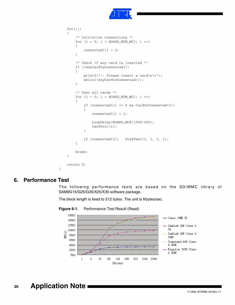
6. Performance TestThe fo l low ing per fo rmance tes ts a re based on the SD/MMC l ib ra ry o fSAM9G15/G25/G35/X25/X35 software package.
The block length is fixed to 512 bytes. The unit is Kbytes/sec.
Figure 6-1. Performance Test Result (Read)
2011126A–ATARM–04-Nov-11
Application Note

Application Note
Figure 6-2. Performance Test Result (Write)
2111126A–ATARM–04-Nov-11

7. Revision History
Document Rev. Comments Change Request Ref.
11126A First issue.
2211126A–ATARM–04-Nov-11
Application Note

Headquarters International
Atmel Corporation2325 Orchard ParkwaySan Jose, CA 95131USATel: (+1) (408) 441-0311Fax: (+1) (408) 487-2600
Atmel Asia LimitedUnit 01-5 & 16, 19FBEA Tower, Millennium City 5418 Kwun Tong RoadKwun Tong, KowloonHONG KONGTel: (+852) 2245-6100Fax: (+852) 2722-1369
Atmel Munich GmbHBusiness CampusParkring 4D-85748 Garching b. MunichGERMANYTel: (+49) 89-31970-0Fax: (+49) 89-3194621
Atmel Japan9F, Tonetsu Shinkawa Bldg.1-24-8 ShinkawaChuo-ku, Tokyo 104-0033JAPANTel: (81) 3-3523-3551Fax: (81) 3-3523-7581
Product Contact
Web Sitewww.atmel.comwww.atmel.com/AT91SAM
Technical SupportAT91SAM SupportAtmel technical support
Sales Contactswww.atmel.com/contacts/
Literature Requestswww.atmel.com/literature
Disclaimer: The information in this document is provided in connection with Atmel products. No license, express or implied, by estoppel or otherwise, to anyintellectual property right is granted by this document or in connection with the sale of Atmel products. EXCEPT AS SET FORTH IN ATMEL’S TERMS AND CONDI-TIONS OF SALE LOCATED ON ATMEL’S WEB SITE, ATMEL ASSUMES NO LIABILITY WHATSOEVER AND DISCLAIMS ANY EXPRESS, IMPLIED OR STATUTORYWARRANTY RELATING TO ITS PRODUCTS INCLUDING, BUT NOT LIMITED TO, THE IMPLIED WARRANTY OF MERCHANTABILITY, FITNESS FOR A PARTICULARPURPOSE, OR NON-INFRINGEMENT. IN NO EVENT SHALL ATMEL BE LIABLE FOR ANY DIRECT, INDIRECT, CONSEQUENTIAL, PUNITIVE, SPECIAL OR INCIDEN-TAL DAMAGES (INCLUDING, WITHOUT LIMITATION, DAMAGES FOR LOSS OF PROFITS, BUSINESS INTERRUPTION, OR LOSS OF INFORMATION) ARISING OUTOF THE USE OR INABILITY TO USE THIS DOCUMENT, EVEN IF ATMEL HAS BEEN ADVISED OF THE POSSIBILITY OF SUCH DAMAGES. Atmel makes norepresentations or warranties with respect to the accuracy or completeness of the contents of this document and reserves the right to make changes to specificationsand product descriptions at any time without notice. Atmel does not make any commitment to update the information contained herein. Unless specifically providedotherwise, Atmel products are not suitable for, and shall not be used in, automotive applications. Atmel’s products are not intended, authorized, or warranted for useas components in applications intended to support or sustain life.
© 2011 Atmel Corporation. All rights reserved. Atmel®, Atmel logo and combinations thereof, and others are registered trademarks or trade-marks of Atmel Corporation or its subsidiaries. ARM®, the ARMPowered® logo and others are registered trademarks or trademarks of ARM Ltd.Other terms and product names may be trademarks of others.
11126A–ATARM–04-Nov-11