capacitors slides by: zil e huma. objectives charging of the capacitors discharging of the...
TRANSCRIPT

CAPACITORSCAPACITORS
SLIDES BY: ZIL E HUMA
OBJECTIVESOBJECTIVES
CHARGING OF THE CAPACITORS DISCHARGING OF THE CAPACITORS DIELECTRIC MATERIALS FACTORS EFFECTING THE VALUES OF
THE CAPACITANCE RESISTIVE-CAPACITIVE SERIES CIRCUITS
AND TIME CONSTANT FORMULA FOR RC TIME FACTOR

CHARGING CHARGING OF THE OF THE
CAPACITORSCAPACITORS
CHARGING OF A CHARGING OF A CAPACITORCAPACITOR
When a capacitor is connected across a voltage source, such as a battery, the voltage forces electrons onto one plate resulting in a negatively charged plate.
The electrons of the other plate are pulled off by the battery resulting in a positively charged plate.
Because the dielectric between the plates is an insulator, current cannot flow through it.
A capacitor has a finite amount of capacity to store charges. When a capacitor reaches its capacity it is fully charged.

Figure 2 shows a circuit containing a conductor Figure 2 shows a circuit containing a conductor connecting a battery, an open switch, and a connecting a battery, an open switch, and a capacitor. The capacitor in Figure 2 is not charged. capacitor. The capacitor in Figure 2 is not charged. There is no potential difference between the platesThere is no potential difference between the plates
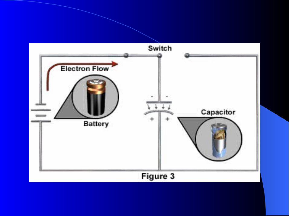
When the switch is closed, as in next Fig., there is a flow of current through the conductor to and from the plates of the capacitor. When the current reaches the negative plate of the capacitor, it is stopped by the dielectric.
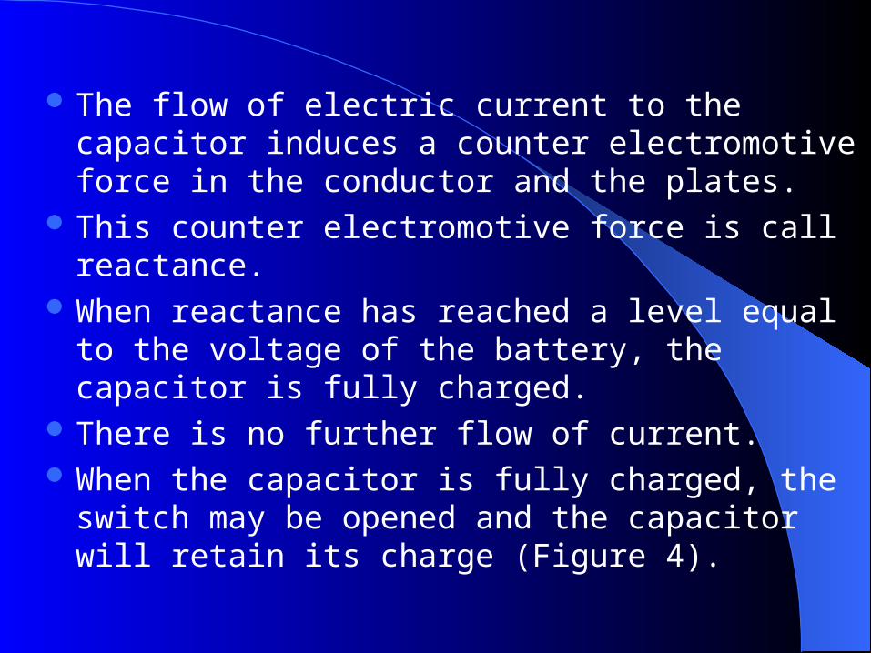
The flow of electric current to the capacitor induces a counter electromotive force in the conductor and the plates.
This counter electromotive force is call reactance.
When reactance has reached a level equal to the voltage of the battery, the capacitor is fully charged.
There is no further flow of current. When the capacitor is fully charged, the
switch may be opened and the capacitor will retain its charge (Figure 4).
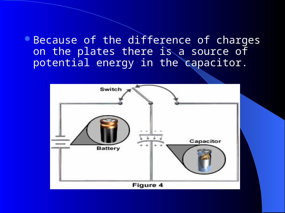
Because of the difference of charges on the plates there is a source of potential energy in the capacitor.
The lines of force between the plates of the capacitor represent an electric force field (see Figures 3 and 4).
This electric force field exists because of the unequal charges, positive and negative, on the inside surfaces of the plates.
Current cannot flow through the electrostatic field because of the dielectric insulator.
In other words, the difference in potential between the plates induces within the dielectric an electrostatic field that retains the charge.

DISCHARGING DISCHARGING OF A OF A
CAPACITORCAPACITOR

DISCHARGING OF A CAPACITORDISCHARGING OF A CAPACITOR The charged capacitor shown in
Figure 4 is now a source of potential energy.
This potential energy is now available for its intended electronic application.
If the switch is closed, as in Figure 5, current will immediately begin to flow through from the negative plate to the positive plate.
The capacitor is discharging.
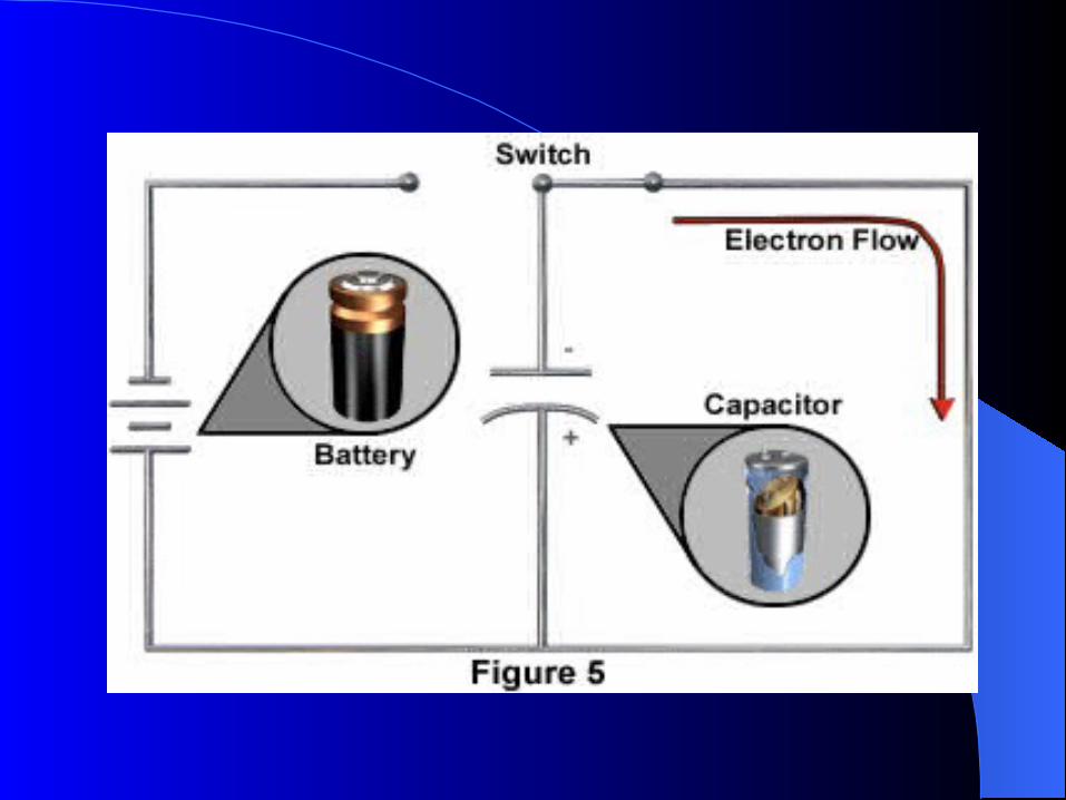

The charged capacitor is the source of voltage for the current flow.
The current will cease flowing when the charges of the two plates are again equal, meaning that the capacitor is completely discharged.

DIELECTRIC MATERIALSDIELECTRIC MATERIALS

DIELECTRIC MATERIALDIELECTRIC MATERIAL
The dielectric material in a capacitor prevents the flow of current between its plates. It also serves as a medium to support the electrostatic force of a charged capacitor. A variety of materials are used for dielectrics.
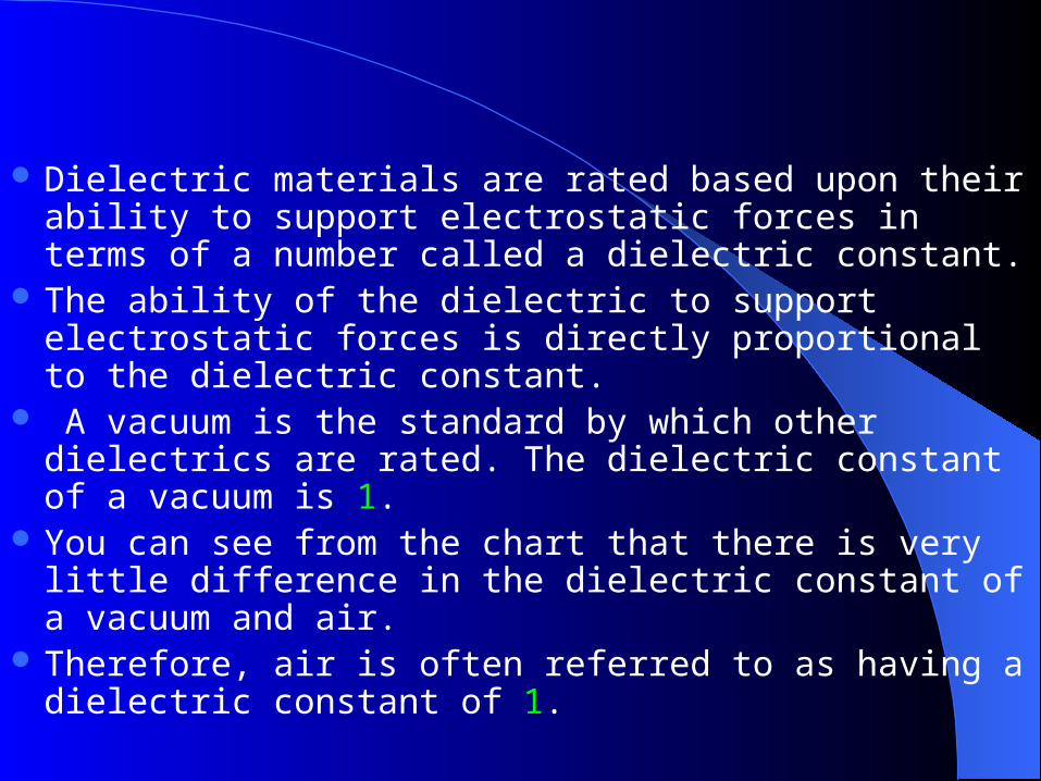
Dielectric materials are rated based upon their ability to support electrostatic forces in terms of a number called a dielectric constant.
The ability of the dielectric to support electrostatic forces is directly proportional to the dielectric constant.
A vacuum is the standard by which other dielectrics are rated. The dielectric constant of a vacuum is 1.
You can see from the chart that there is very little difference in the dielectric constant of a vacuum and air.
Therefore, air is often referred to as having a dielectric constant of 1.
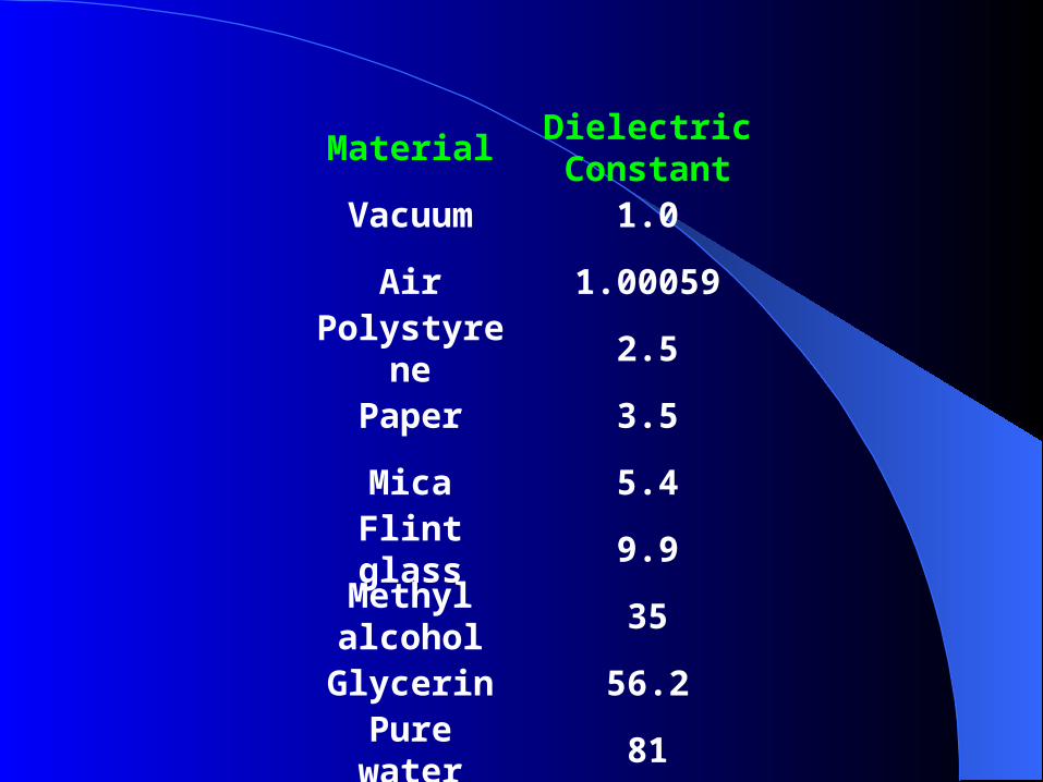
MaterialDielectricConstant
Vacuum 1.0
Air 1.00059Polystyren
e2.5
Paper 3.5
Mica 5.4
Flint glass 9.9Methyl alcohol
35
Glycerin 56.2
Pure water 81

Factors Affecting Value of Factors Affecting Value of CapacitanceCapacitance
The capacitance of a capacitor is affected by three factors:
1. The area of the plates 2. The distance between the plates 3. The dielectric constant of the
material between the plates
Larger plates provide greater capacity to store electric charge. Therefore, as the area of the plates increase, capacitance increases.
Capacitance is directly proportional to the electrostatic force field between the plates. This field is stronger when the plates are closer together. Therefore, as the distance between the plates decreases, capacitance increases. As the distance between the plates increases, capacitance decreases.
RESISTIVE RESISTIVE CAPACITIVECAPACITIVE
SERIES CIRCUITS SERIES CIRCUITS AND AND
TIME CONSTANTTIME CONSTANT
Resistive-Capacitive Series Resistive-Capacitive Series
Circuits and Time ConstantCircuits and Time Constant As a capacitor becomes charged, the
current flow decreases because the voltage developed by the capacitor increases over time and opposes the source voltage.
Therefore, the rate of charge of a capacitor is reduced over time.

The amount time required to charge and discharge a capacitor is a very important factor in the design of electronic circuits.
Resistors are often used in combination with capacitors in order to control the charge and discharge time necessary for the intended application
Resistance directly affects the time required to charge a capacitor. As resistance increases, it takes more time to charge a capacitor.
The amount of time for the capacitor to become fully charged in a resistive-capacitive (RC) circuit depends on the values of the capacitor and resistor.

The following graph shows the rate of charge of a capacitor in a RC circuit
Note that the rate of charge greatly decreases over time. The latter part of its charging time is many times longer than the
first part. In fact, a capacitor reaches 63.2% of its charge in one fifth of
the time it takes to become fully charged. Because of this, capacitors in actual applications are generally
not fully charged. Capacitors in circuits are generally charged to just 63.2% of full
capacity. The time required for a capacitor to charge to 63.2% of its full
capacity is referred as its RC (resistive-capacitive) time constant.

FORMULA FOR RC TIME FACTORFORMULA FOR RC TIME FACTOR
The RC time constant of a circuit can be calculated by using the following formula
t = C x R Where t is time in seconds, C is
capacitance in farads, and R is resistance in ohms.