capacitor sounds 6 - 10 to 100 mf capacitors and 100 hz ... ew 01... · 1 capacitor sounds 6 - 10...
TRANSCRIPT

1
Capacitor Sounds 6 - 10 to 100 µµF capacitors and 100 Hz measurements.Updated & expanded March 2003
Original version Pub. Electronics World Jan 2003 - C. BatemanReaders of my articles have now seen that many capacitors introduce distortions onto a pure sinewave. In some instances thisdistortion results from the unfavourable loading the capacitor imposes onto its valve or semiconductor driver. More often, thecapacitor generates the distortion within itself.
For 1 µF, the lowest distortions are generated by choosing a film capacitor or a Bi-polar electrolytic. Polar aluminiumelectrolytics produced considerably larger distortions, even when tested with small AC signals. Ref. 1
While high capacitance, low cost, electrolytic capacitors, can be obtained from distributors. Low cost metallised film capacitorsare restricted typically to 10 µF at 100 volt and 22 µF at 63 volt.
In this final article, which completes last months discussion on electrolytic capacitors, we explore whether a metallised filmcapacitor or an electrolytic is our economic, low distortion choice, for capacitors at 10 µF to 100 µF values.
Test frequency.To avoid overstressing large value electrolytic capacitors, we should reduce our test signal frequency towards 100 Hz. Butsufficiently above or below this frequency, to discriminate between harmonics of the supply mains and the test capacitor.
With minor changes in capacitance values, the PCB used for our 1 kHz oscillator can provide an exceptionally low distortion100 Hz test signal. Ref. 2 In similar fashion the PCB used for our 1 kHz notch filter and pre-amplifier can also be used at thisfrequency. Ref. 3
The AD811 low distortion buffer can output 40 mA. At 100 Hz using a 100Ω series resistor, it can develop a 5 volt test signalacross a 10 µF capacitor. Using a 10Ω resistor, 0.5 volts could be developed across a 100 µF capacitor.
These test voltages are more than sufficient to distortion test any electrolytic capacitor up to 100 µF. However when I designedthe test instruments I decided to provide the ability to measure both values of film capacitors to 5 volts. To produce a larger testsignal with 100 µF capacitors, a more powerful buffer must be used. A low distortion circuit able to drive up to 400 mA hasbeen designed but needs a different PCB. see Fig. 1
Fig. 1) High power buffer provides low distortion, a gain of two and a 400 mA output. It can develop more than five voltsacross a 100 µF capacitor via a 10 Ω current limiting resistor.

2
When testing large value capacitors, a four terminal test system is preferred. Four BNC connectors are provided. which accepteither Hewlett Packard capacitor test jigs or four discrete cables and crock clips. see Fig. 2
Fig. 2) The higher power100 Hz test system.Four BNC connectors,are arranged to acceptHewlett Packard test jigfixtures.
The DC bias networkinserts between thisbuffer amplifier andthe test jig fixture.
Alternately instead of theHewlett Packard test jigs,this buffer amplifier canbe used with four BNCtest leads fitted with‘crock’ clips.
Box 100 Hz test equipment.The oscillator and notch filter printed boards can be used at other frequencies by scaling the values of a few capacitors. Ref. 2
Oscillator board.For 100 Hz use 100 nF 1% metallised Polypropylene for C1, C2, and C3. Bypass R16 by a wire link. To differentiate betweentest capacitor and mains frequency harmonics, replace R23, R24 and R25 with wire links.
Notch filter/pre-amplifier board.For 100 Hz use 100 nF 1% metallised Polypropylene for C41, C42, C43, C44, C47 and C48. Use 47 nF 1% metallisedPolypropylene for C45 and C46. Use 10 nF 1% metallised Polypropylene for C49.
Output Buffer.At 100 Hz, 10 µF capacitors can be tested to 5 volts, using the AD811 output buffer amplifier described. Ref. 3 Adding a 10Ohm current limiting resistor allows 100 µF to be tested to 0.5 volts.
To fully test 100 µF capacitors, a higher power buffer amplifier is needed. It should develop at least 5 volts signal across a100 µF capacitor via a 10 Ohm current limiting resistor. I designed a buffer amplifier and printed circuit board, able to drive upto 7 volt or 400 mA, with extremely low distortion. An Elantec EL2099CT output amplifier is used with an input buffer. Thiscan be an OP295, OPA2134 or an NE 5532A, by connecting one link.. I used an OPA2134 in my prototype. see Fig. 1
Larger decoupling capacitors are used with 1.5 Amp stabilisers. A Perancea 75 by 50 mm PCB case serves as heat sink for theEL2099CT and the stabilisers. Apart from these changes, the buffer amplifier schematic circuit and the current limitingresistors/switch follow the approach previously used for my 1 kHz AD811 output buffer.
When testing 100 µF, a four wire test method should be used. Four BNC connectors, two to output the test current and two tomeasure the capacitor distortions, are spaced at 22 mm centres to fit Hewlett Packard capacitor test jigs alternately four discreteBNC cables and crock clips can be used.
To measure capacitors larger than 10 µF with DC bias voltage, a DC blocking buffer circuit as already described but made withlarger capacitors is essential.
Two 50 µF 450 volt metallised Polypropylene motor run capacitors, replaced the 11 µF current carrying capacitors of my1 kHz design. Three 3.3 µF MKP capacitors provide 10 µF for the voltage measuring circuit. These components were mountedin a die-cast box and hardwired.
Four BNC connectors, were mounted on opposite sides of this box, to mate with my 100 Hz output buffer amplifier and theHewlett Packard capacitor test jigs. see Fig. 2
A selectable DC bias voltage was provided, by mounting 20 AA cells and a range switch, in a second die cast box. This wasused with both DC blocking buffer designs.

3
Tantalum bead capacitors.Some audio power amplifier designs have used small Tantalum bead capacitors, with apparent success. Initial measurements ofa number of Tantalum capacitors revealed large distortions. Measured at 0.3 volts with and without DC bias, my Tantalumcapacitor stocks produced at least ten times more distortion than found with low cost polar Aluminium electrolytics. I decidedto exclude Tantalum bead capacitors from further tests. see Fig.3
Fig. 3) Distortion of thisTantalum bead capacitor,is ten times worse thanfound with similar valueand voltage aluminiumelectrolytic capacitors.
Distortion does reduceslightly with applicationof DC bias.
Aluminium Electrolytic capacitor myths.As with other capacitor types, much has previously been written about the sound distortions electrolytics produce. As a result,many false myths, specific to electrolytics have emerged. Most were discussed in my last article, the remainder in this.
a) High ESR Electrolytics degrade sound quality, low ESR is always best.b) Electrolytics are highly inductive at audio frequencies.c) Polar electrolytics should be biased to half rated voltage to reduce distortion.d) Electrolytic capacitor distortion is mostly third harmonic.
A working knowledge of aluminium electrolytic capacitor construction combined with careful measurements, leads tosomewhat different conclusions.
Is a low ESR/tanδδ capacitor always better ?Capacitor makers test every production capacitor for four key parameters. Capacitance, tanδ, insulation resistance and voltagewithstand. The need to test for capacitance, insulation resistance and voltage withstand is obvious, but why test tanδ ?
The most nearly perfect capacitor needs conducting electrodes, which inevitably have some resistance. This appears in serieswith the capacitive reactance to degrade the theoretical -90° of phase difference to a smaller negative angle. As a result thecomplementary angle called δ (delta) increases. Every practical capacitor also incurs losses in its insulators and dielectricsystem. These further degrade this phase difference, increasing the angle δ.
The ratio of these resistive losses to the capacitors reactance or tanδ is the simplest way to monitor capacitor quality. As lossesincrease so does this ratio and the tangent of the angle δ, usually called tanδ. Consequently a large tanδ implies large resistivelosses. These losses do not exist as discrete resistors so are described as ‘equivalent series resistance’ conveniently abbreviatedto ESR. Tanδ and ESR are not finite values but do vary widely with change of measurement frequency.
The most nearly perfect capacitor would exhibit near zero ESR. Low ESR is essential for use in switched mode power supplies,but does a low ESR electrolytic ensure low audio distortion ?
Of the 100 µF capacitors I tested, the 10 volt Oscon measured the lowest 100 kHz ESR of all, 0.012 Ω and 100 Hz tanδ of0.035. It would be unreasonable to compare a 10 volt capacitor with higher voltage types so I also measured 10 volt RubyconYXF and Elna RSH types. The YXF ESR measured 0.550 Ω, tanδ 0.091. The RSH ESR was 0.505 Ω and tanδ 0.104.
Tested at 0.5 volt with and without 6 volts DC bias, the Rubycon YXF produced the least distortion, 0.0351% with DC bias and0.00331% unbiased. The Oscon distorted worst of the three, measuring 0.05321% with DC bias and 0.02499% unbiased.
Clearly low tanδ at 100 Hz and low ESR at 100 kHz does not ensure low audio distortion.

4
Are Electrolytics Inductive at audio frequencies?Radial lead electrolytics are assembled with their connecting tabs attached towards the centre of their anode and cathode foils.Wound together this produces a near non-inductive winding. As explained in my last article, the main contribution to thecapacitor’s self inductance then comes from the connecting leadwires and tabs, and not the wound element. Ref. 4
This ‘inductive at audio frequencies’ myth is easily proved to be false. The largest capacitor I measured for distortion, the Nitai220 µF 63 volt Bi-polar, has a case size 25×16 mm. Apart from in the power supply, this is the largest value commonly used inan audio system. I mounted one on a test jig, its self resonant frequency was 250 kHz, well above audible frequencies. Ref. 5
At all audio frequencies this capacitor must present a capacitive reactance. Self inductance of a lesser value or smaller case sizeradial lead capacitor being even less, self resonance of smaller capacitors will occur at higher frequencies. They cannot becomeinductive at audio frequencies.
Exceptionally large value capacitors, as often used in power supplies, may appear as either inductive or capacitive dependingon their capacitance value, case size and their connecting leadwires/tracks. Inductance of the leadwires/circuit tracks used toconnect the capacitor, usually well exceed that of the capacitor’s own self inductance. Due to its internal series resistance orESR the capacitor’s phase angle will be much smaller than -90° and the capacitor will appear to the circuit as a seriescombination of a resistor with a capacitor or as a DC blocking inductance in series with a resistor.
Using a Wayne Kerr B6425 precision LCR meter fitted with my Hewlett Packard capacitor test jigs, I measured a fewcapacitors removed from one of my old bench amplifiers at 10 kHz, as representative of capacitors which may be used inamplifier power supplies, to illustrate the point:-
Elna 4,700 µF 63 volt Cerafine size 82 mm by 35 mm dia, phase angle +7.5°, ESR 11.05 mΩ Impedance 18.3 mΩMarcon 4,700 µF 63 volt size 30 mm by 40 mm dia, phase angle -6.5°, ESR 16.65 mΩ Impedance 16.69 mΩMarcon 10,000 µF 63 volt size 42 mm by 65 mm dia, phase angle -14.5°, ESR 9.68 mΩ Impedance 10.0 mΩ
At 20 kHz both Marcon types remained as a capacitive reactance having a negative phase angle. At 100 kHz the Elna measuredas an 83 nH inductor, the 4700 µF Marcon as a 26 nH inductor while the 10,000 µF Marcon measured as a 256 µF capacitor.
This last value shows why it is not possible to estimate capacitor self inductance from published impedance/frequency curves.As frequency increases, the capacitance of all aluminium electrolytic capacitors reduces, some more quickly than others. As thecapacitive reactance reduces with frequency, the capacitors ESR becomes almost a constant value. Phase angles become smalland the impedance curve becomes ‘flat bottomed’. see Fig. 4
Any calculation of resonant frequency based on using the correct self inductance value together with this capacitors nominal10,000 µF value, obviously produces a very false result.
Measured using the Wayne Kerr B6425 with Hewlett Packard test jigs as above, this Philips 1000 µF capacitor exhibited a -6°phase angle and 820 µF capacitance at 30 kHz. At this frequency ESR measured 61.5 mΩ, impedance was 61.6 mΩ.
Fig. 4) This 1000 µF 25volt capacitor has beenmeasured using two quitedifferent methods.
The Wayne Kerr bridgeup to 300 kHz, itsmaximum frequency.
This graph was plotted upto 10 MHz from resultsusing my ‘High-frequency impedancemeter’ with jigs andmethods as in EWJanuary 2001.
As can be seen bothmethods gave almostidentical results.
Phase v Impedance
0.1 1 10 100 1,000 10,000-100
-50
0
50
100
0
0.4
0.8
1.2
1.6
2
Frequency kHz
Phase degrees Impedance
1000 µF 25v Philips 135 Capacitor.

5
Polar electrolytics.In my last article we saw that every polar aluminium electrolytic capacitor comprises two polar capacitors in series, back toback. Ref. 1 Wound with an anode and cathode foil, each foil with the electrolyte, comprises one capacitor. The cathode foilprovides a larger capacitance, lower working voltage, than the anode foil.
With no bias voltage, the capacitor produced predominantly second harmonic distortion. In some instances, application of avery small optimum DC bias did minimise this second harmonic. Increased bias however resulted in increased second harmonicdistortion.
For the 100 µF 25 volt capacitors tested for this article, optimum bias varied by capacitor, from 1.1 to 4.2 volts. Optimum biasvoltage varies with capacitor rated voltage, capacitance value and even from capacitor to capacitor within a small batch.However the important point is that with all the polar aluminium electrolytic capacitors I tested, (several hundred in all ) thisoptimum low distortion bias with no exceptions, was a small voltage. Not the half rated voltage as commonly suggested.
Bi-polar electrolytics.A Bi-polar electrolytic is made in exactly the same way as a polar capacitor, with one important difference. In place of theunformed cathode foil we use a second, formed, anode foil.
We still have two polar capacitances in series, back to back, both now the same value and voltage. To make the desired value,two anode foils of double capacitance are used.
Aluminium electrolytic capacitor designers are accustomed to mixing and matching their available materials, to suit thecapacitor’s end application. So it should not surprise that some designs are semi Bi-polar, i.e. they are made using a lowervoltage deliberately ‘formed’ anode foil as cathode.
Equivalent circuit.Using this constructional background, we deduced an equivalent circuit for a polar aluminium electrolytic capacitor. see Fig.5
Fig 5) Simplifiedequivalent schematicshows how a polarelectrolytic capacitorbehaves with AC signals,with and without DCbias.
Dielectric Oxide. Aluminium oxide has a ‘k’ of eight, similar to that of COG ceramics or some impregnated paper capacitors.Ref. 6 It is higher than PET, which at 3.3, has the highest ‘k’ of commonly used film dielectrics. It is a low value compared tothe ‘k’ of some thousands, found in ‘high k’ BX, X7R and Z5U ceramics.
More significant is dielectric thickness. Aluminium electrolytic dielectric is much thinner than used in other capacitors and thedielectric oxide film has a small but easily measured voltage coefficient of capacitance, typically +0.1% with +18v DC bias, butthis is overshadowed many times by its much larger dielectric absorption. An electrolytic capacitor is exceptionally sensitive todielectric absorption effects and the applied AC and DC voltages.
Voltage effects.When our 1 µF 63 volt polar electrolytic was tested using two 0.7 volt frequencies, its third harmonic was -110 dB or 0.0003%.It created visible intermodulation distortion. We also noted small capacitors rated at 40 to 63 volt exhibit near optimum quality.Ref. 1
Many 100 µF capacitors will be made with lower voltage, thinner dielectric oxide, anode foil. This capacitance requires lengthyanode and cathode foils, housed in a larger diameter can. To generate the test voltage across the capacitor, increased currentmust pass through the tab connections into the winding, amplifying the affects of any non-linear resistance. It seems probablethat similar harmonic and intermodulation levels will be found but at smaller test voltages.

6
To allow direct comparison between the low cost 1 µF 63 volt polar capacitor and the physically larger Elna Silmic 100 µF 25volt, I show its distortions measured at 1 volt. This capacitor provided the best 1 volt, no bias, results of the 100 µF polar typestested for this article. see Fig. 6
Fig 6) The lowestdistorting 100 µF 25 voltpolar capacitor of thosetested, at 1 volt. It shouldbe compared with Figure6 (Fig 7 as published inEW) of my last article.
Both capacitors producedsimilar second harmonics.Third harmonic of the100 µF has increased by4.5 dB indicative ofincreasing non-linearitywith increasingcapacitance values.
Lower voltage measurements.Accurate 100 Hz distortion measurements using test signals smaller than 1 volt become quite difficult, for two main reasons.
Supply mains harmonics intrude everywhere and are difficult to reduce using a computer based system.The smaller test signal reduces the dynamic range of our measurement, dramatically inflating indicated distortion.
For example, using a 0.1 volt test signal, my noise floor is around -112 dB, hence a perfect capacitor producing no distortion atall will still register some 0.0005%. However if we compare the measured harmonic levels of our electrolytic with those foundfor the identical measurement using a metallised film capacitor. We will see any increase in distortion caused by the electrolyticcapacitor.
To distinguish between harmonics from the mains and the test capacitor, my test frequency was displaced a few Hz away from100 Hz. The Spectra software then ignores mains harmonics when calculating distortions. To assist visual identification, I used‘Mains’ markers to identify mains harmonics and amplitude markers to indicate the first four harmonics from the test capacitor.
At 100 µF, a metallised Polypropylene capacitor is both large and costly. I used an assembly of 10 µF Evox Rifa MMKmetallised PET capacitors. This works well for small test voltages as a low distortion ‘reference’ capacitor. see Fig. 7
Fig. 7) Distortion plot ofan assembly of ten EvoxRifa 10 µF 63 volt MMKmetallised PETcapacitors, tested at0.5 volt.
This 100 µF assemblywas then used as thedistortion reference foreach 100 Hz low voltagedistortion test.
N.B. Labels ‘Mains’indicate 150 and 250 Hzharmonics of the 50 HzAC supply mains.
7
Electrolytic distortion.Despite some marketing claims, capacitors are not categorised for distortion so a distorting capacitor would not be considereddefective by its maker. It is the responsibility of the equipment designer to select the correct capacitor for each circuit.
During this investigation I measured many other polar electrolytic capacitors, rated from 10 to 100 volt and with capacitanceranging from 1 to 220 µF, produced by several different, major manufacturers.
To illustrate this article, I decided to measure three quite different 100 µF 25 volt polar electrolytic capacitors and mymetallised PET assembly. The low cost Rubycon YXF, typical of a modern miniature low ESR capacitor, the much larger andmore expensive Elna Silmic and the considerably more expensive Black Gate FK, physically larger than the Elna Silmic.
The Black Gate FK is a 21×10 mm semi Bi-polar, built using a low voltage anode as its cathode foil. The Silmic is 17×10 mmand uses a special separator paper incorporating silk extracts. Both were purchased from Audiocom UK.
The Rubycon YXF is a 12×6.5 mm conventional, miniature, low ESR low cost capacitor purchased from Farnell.
Tests were performed using 0.1 volt AC to 0.5 volt AC in 0.1 volt steps, each using DC bias voltages of 0 volt, 6 volt, 12 voltand 18 volt, a total of 65 separate distortion measurements.
100 µµF 25 volt tests.With the 0.1 volt test signal, measurement noise floor was reduced to -112 dB. With no bias, distortions for the PET referencecapacitor and the Black Gate FK were lost in this noise. Second harmonic for the Silmic measured -106.1 dB and the YXFmeasured -102.8 dB.
With 6 volt DC bias, second harmonic for the Black Gate FK measured -99 dB, the Silmic measured -99.5 dB and the YXFmeasured -93.5 dB.
With 12 volt DC bias, second harmonic for the Black Gate FK increased to -95.9 dB, the Silmic was -94.4 dB and the YXFmeasured -91.8 dB.
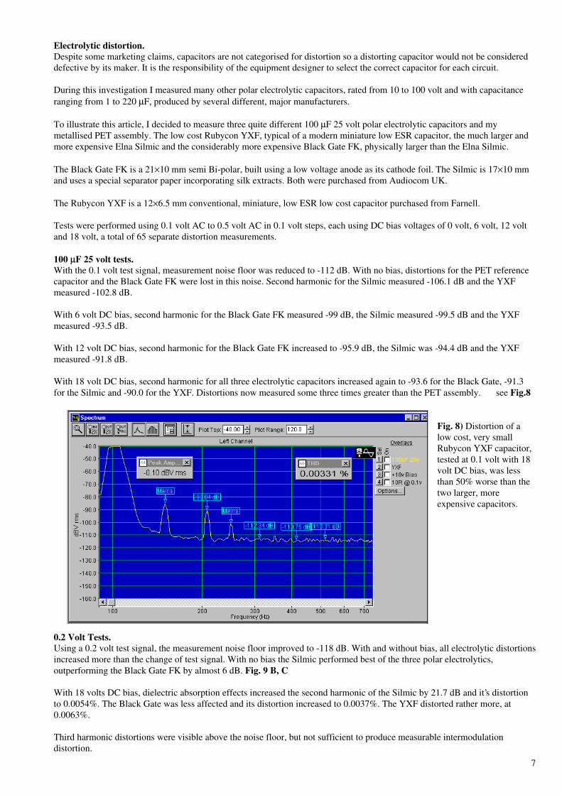
With 18 volt DC bias, second harmonic for all three electrolytic capacitors increased again to -93.6 for the Black Gate, -91.3for the Silmic and -90.0 for the YXF. Distortions now measured some three times greater than the PET assembly. see Fig.8
Fig. 8) Distortion of alow cost, very smallRubycon YXF capacitor,tested at 0.1 volt with 18volt DC bias, was lessthan 50% worse than thetwo larger, moreexpensive capacitors.
0.2 Volt Tests.Using a 0.2 volt test signal, the measurement noise floor improved to -118 dB. With and without bias, all electrolytic distortionsincreased more than the change of test signal. With no bias the Silmic performed best of the three polar electrolytics,outperforming the Black Gate FK by almost 6 dB. Fig. 9 B, C
With 18 volts DC bias, dielectric absorption effects increased the second harmonic of the Silmic by 21.7 dB and it’s distortionto 0.0054%. The Black Gate was less affected and its distortion increased to 0.0037%. The YXF distorted rather more, at0.0063%.
Third harmonic distortions were visible above the noise floor, but not sufficient to produce measurable intermodulationdistortion.
8
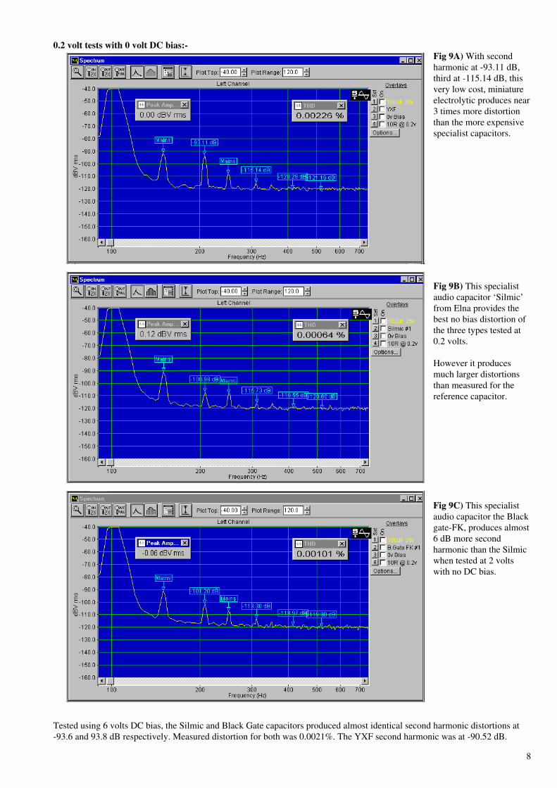
0.2 volt tests with 0 volt DC bias:-Fig 9A) With secondharmonic at -93.11 dB,third at -115.14 dB, thisvery low cost, miniatureelectrolytic produces near3 times more distortionthan the more expensivespecialist capacitors.
Fig 9B) This specialistaudio capacitor ‘Silmic’from Elna provides thebest no bias distortion ofthe three types tested at0.2 volts.
However it producesmuch larger distortionsthan measured for thereference capacitor.
Fig 9C) This specialistaudio capacitor the Blackgate-FK, produces almost6 dB more secondharmonic than the Silmicwhen tested at 2 voltswith no DC bias.
Tested using 6 volts DC bias, the Silmic and Black Gate capacitors produced almost identical second harmonic distortions at-93.6 and 93.8 dB respectively. Measured distortion for both was 0.0021%. The YXF second harmonic was at -90.52 dB.
9
0.2 volt tests with 18 volt DC bias:-
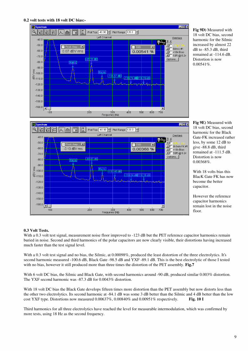
Fig 9D) Measured with18 volt DC bias, secondharmonic for the Silmicincreased by almost 22dB to -85.3 dB, thirdremained at -114.6 dB.Distortion is now0.00541%.
Fig 9E) Measured with18 volt DC bias, secondharmonic for the BlackGate-FK increased ratherless, by some 12 dB togive -88.8 dB, thirdremained at -111.5 dB.Distortion is now0.00368%.
With 18 volts bias thisBlacK Gate FK has nowbecome the bettercapacitor.
However the referencecapacitor harmonicsremain lost in the noisefloor.
0.3 Volt Tests.With a 0.3 volt test signal, measurement noise floor improved to -123 dB but the PET reference capacitor harmonics remainburied in noise. Second and third harmonics of the polar capacitors are now clearly visible, their distortions having increasedmuch faster than the test signal level.
With a 0.3 volt test signal and no bias, the Silmic, at 0.00098%, produced the least distortion of the three electrolytics. It’ssecond harmonic measured -100.6 dB, Black Gate -98.5 dB and YXF -89.1 dB. This is the best electrolytic of those I testedwith no bias, however it still produced more than three times the distortion of the PET assembly. Fig.7
With 6 volt DC bias, the Silmic and Black Gate, with second harmonics around -90 dB, produced similar 0.003% distortion.The YXF second harmonic was -87.3 dB for 0.0043% distortion.
With 18 volt DC bias the Black Gate develops fifteen times more distortion than the PET assembly but now distorts less thanthe other two electrolytics. Its second harmonic at -84.1 dB was some 3 dB better than the Silmic and 4 dB better than the lowcost YXF type. Distortions now measured 0.00637%, 0.00840% and 0.00951% respectively. Fig. 10 I
Third harmonics for all three electrolytics have reached the level for measurable intermodulation, which was confirmed bymore tests, using 18 Hz as the second frequency.

10
0.3 volt tests with 0 volt DC bias:-Fig 10A) Measured at 0.3volts but no DC bias,second harmonic for theYXF at -89.1 dB wassome 10 dB larger thanfor the two specialistcapacitors.Distortion has increasedto 0.00354%.
Fig 10B) Measured at0.3 volts but no DC bias,second harmonic for theSilmic at -89.1 dB wasagain the best polarcapacitor of the three Imeasured.Distortion has increasedto 0.00098%.
Fig 10C) Measured at 0.3volts but no DC bias,second harmonic for theBlack Gate-FK was some2 dB worse at -89.1 dBthan measured for theSilmic.Distortion now measures0.00126%.
11
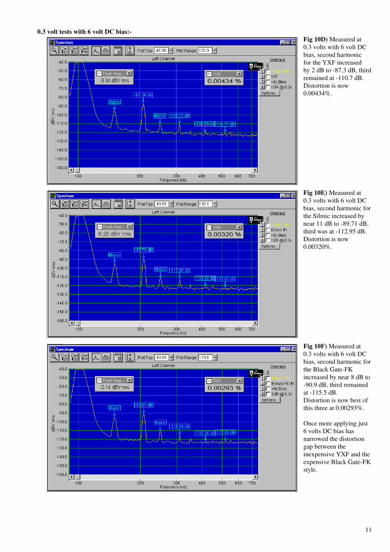
0.3 volt tests with 6 volt DC bias:-Fig 10D) Measured at0.3 volts with 6 volt DCbias, second harmonicfor the YXF increasedby 2 dB to -87.3 dB, thirdremained at -110.7 dB.Distortion is now0.00434%.
Fig 10E) Measured at0.3 volts with 6 volt DCbias, second harmonic forthe Silmic increased bynear 11 dB to -89.71 dB,third was at -112.95 dB.Distortion is now0.00320%.
Fig 10F) Measured at0.3 volts with 6 volt DCbias, second harmonic forthe Black Gate-FKincreased by near 8 dB to-90.9 dB, third remainedat -115.5 dB.Distortion is now best ofthis three at 0.00293%.
Once more applying just6 volts DC bias hasnarrowed the distortiongap between theinexpensive YXF and theexpensive Black Gate-FKstyle.

12
0.3 volt tests with 18 volt DC bias:-Fig 10G) Measured at 0.3volts with 18 volt DCbias, second harmonic forthe YXF increased bynearly 9 dB to -80.5 dB,third remained unchangedat -110.9 dB.Distortion has increasedsignificantly and is now0.00951%.
I consider this distortionis far too high for use inthe signal path of anaudio system.
Fig 10H) Measured at 0.3volts with 18 volt DCbias, second harmonic forthe Silmic increased bysome 19 dB to -81.3 dB,third continues at -113dB.Distortion is now0.00840%.
I consider this distortionis also far too high for usein an audio system.
Fig 10I) Measured at 0.3volts with 18 volt DCbias, second harmonic forthe Black Gate-FKincreased by some 14 dBto -84.1 dB, thirdremained at -115.2 dB.Distortion is again best ofthe three at 0.00637%.
I consider this distortionis far too high for use inan audio system.
Increasing DC bias to18 volts has had adisastrous effect ondistortion for all threetypes.
All three electrolytics produced significant distortions in these 0.3 volt tests. Almost five times larger with no bias, at leastfifteen times larger with bias, than my PET assembly. I consider distortions from these 100 µF polar capacitors tested at 0.3volts, far exceed the sensible limit for use in the signal path of high quality audio.

13
Using a Film Shunt.Some writers advocate using a low distortion film capacitor in parallel with an electrolytic, to reduce distortion. Does it work ?To find out I made a few measurements on these capacitors using a 1 volt test signal, unbiased then with 18 volt DC bias. Asshunt I used my low distortion 1 µF MKP also a 10 µF bank of three 3.3 µF low distortion metallised PPS capacitors.
With 1 µF shunt, second and third harmonics of the Silmic reduced by just 1 dB. Using the 10 µF, both harmonics reduced by afurther 1 dB. This small reduction is not worth the additional PCB space and extra cost, because even with a 10 µF shunt,distortions far exceed those of my metallised PET assembly.
Fig 11A) Re-measured at1 volt without DC biasbut using the 10 µF filmcapacitor as shunt, wefind second harmonic hasreduced by only 1.5 dBDistortion was 0.00184%is now 0.00151%.
Fig 11B) Measured at 1volt with 18 volts DCbias and using the 10 µFfilm capacitor as shunt,we find second harmonicincreased to -68 dB.Distortion is 0.03973% .
I consider thesedistortions are far toohigh for use in the signalpath of an audio system.
Perhaps a higher voltage capacitor would measure better, or would its much larger area anode and cathode foils simply makematters worse ?
100 µµF 50 volt tests.Examination of my earlier distortion plots suggested the only suitable 100 µF electrolytic types I had which might measurelower distortion were the 22×12.5 mm 50 volt Silmic and the 26×12.5 mm 50 volt Panasonic S Bi-polar, Farnell 218-698.
With 0.3 volt test signal and no bias, the 50 volt Silmic distorted more than the 25 volt version. Because of its much longer andwider foils, second harmonic increased 2 dB, third increased 7 dB and distortion measured 0.00134%. see Fig.12A
Due to the thicker dielectric used for the 50 volt capacitor, with 18 volt DC bias, second harmonic increased less, now almost6 dB smaller than the 25 volt version. Distortion at 0.00460% was just over half that of the 25 volt version.

14
Comparison tests, 100 µµF 25 volt and 50 volt rated ‘Silmic’ capacitors.Fig 12A) Measured withno DC bias at 0.3 volt,we find second harmonichas increased by 2 dB andthird harmonic by 7 dBwhen compared with the25 volt capacitor.Distortion has increasedto 0.00134% for 50 voltcapacitor, from 0.00098%for the 25 volt version.
Fig 12B) Measured with6 volt bias at 0.3 volt, wefind second harmonic hasincreased by another 3.5dB but third harmonic at -105.6 dB has notchanged.Distortion now0.00185%.
Fig 12C) Measured with18 volt bias at 0.3 volt,we find second harmonichas increased by almost12 dB, third harmonic at-105.9 dB unchanged.Distortion now0.00460%.
15
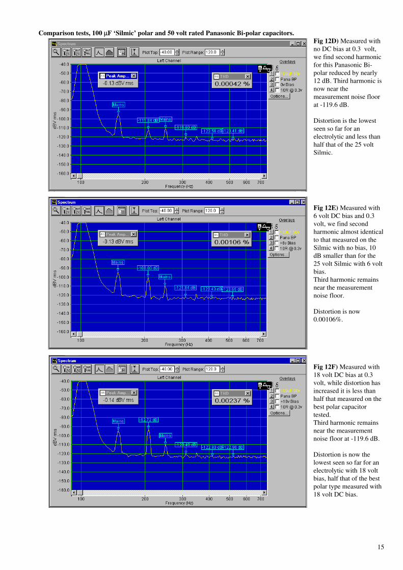
Comparison tests, 100 µµF ‘Silmic’ polar and 50 volt rated Panasonic Bi-polar capacitors.Fig 12D) Measured withno DC bias at 0.3 volt,we find second harmonicfor this Panasonic Bi-polar reduced by nearly12 dB. Third harmonic isnow near themeasurement noise floorat -119.6 dB.
Distortion is the lowestseen so far for anelectrolytic and less thanhalf that of the 25 voltSilmic.
Fig 12E) Measured with6 volt DC bias and 0.3volt, we find secondharmonic almost identicalto that measured on theSilmic with no bias, 10dB smaller than for the25 volt Silmic with 6 voltbias.Third harmonic remainsnear the measurementnoise floor.
Distortion is now0.00106%.
Fig 12F) Measured with18 volt DC bias at 0.3volt, while distortion hasincreased it is less thanhalf that measured on thebest polar capacitortested.Third harmonic remainsnear the measurementnoise floor at -119.6 dB.
Distortion is now thelowest seen so far for anelectrolytic with 18 voltbias, half that of the bestpolar type measured with18 volt DC bias.

16
Bi-polar.The Panasonic S Bi-polar capacitor at 0.3 volt with no bias, produced less than half the distortion of the 25 volt Silmic. Secondharmonic measured -111.8 dB, third -119.6 dB and distortion 0.00042%.
With 18 volt DC bias, second harmonic increased to -92.7 dB and distortion to 0.00237%, half the distortion of the 50 voltSilmic.
The Panasonic S Bi-polar produced the lowest distortion of all single 100 µF electrolytic capacitors of those I tested, using a0.3 volt signal and DC bias from 0 volt to 18 volts. see Fig.12 D/F
In my last article we saw how using two polar capacitors in series could reduce distortion. Let us now explore using two Bi-polar capacitors in series.
Two better than one?I already had some 220 µF 63 volt Nitai Bi-polar electrolytics, Farnell 317-4906. Two connected together in series wouldapproximate 100 µF.
Measured at 0.3 volts with no bias, second harmonic level reduced 6 dB compared to the Panasonic S Bi-polar. With secondand third harmonics buried in the noise floor, distortion at 0.00033% measured the same as the PET assembly.
With 18 volt DC bias, second harmonic measured -105.3 dB and distortion 0.00063%. A near four fold improvement comparedto the Panasonic S Bi-polar, more than seven times better than the best polar capacitor tested.
Fig 13) Series pair of 220µF 63 volt Nitai Bi-polarelectrolytics, measuredwith 18 volt DC bias at0.3 volt, second harmonicdistortion has reduceddramatically. It is nowseven times smaller thanmeasured on the bestpolar capacitor tested.
Third harmonic remainson the measurement noisefloor.
To better compare harmonics I examined performances using a 0.5 volt signal. With no bias, those for my PET assembly canjust be seen emerging from noise. Second harmonic -124.3 dB, third -123.9 dB and distortion 0.00020%. see Fig 7
The double 220 µF 63 volt Bi-polar second harmonic -117.7 dB, third -124.1 dB, and distortion 0.00023%, measuredpractically the same distortion as the PET assembly. see Fig.14A
With 18 volt DC bias, second harmonic of the double Bi-polar increased to -100.7 dB and distortion to 0.00093%, slightlymore than double the distortion measured on the PET assembly with this bias. see Fig.14C
This is an excellent performance from a pair of inexpensive electrolytic capacitors, but how does this series pair of Bi-polarcapacitors stack up for size and cost ? Can this Bi-polar series pair still produce low distortion tested with a 1 volt signal ?
At 1 volt with no bias, noise floor improved to -132 dB. Distortion of the PET assembly measured 0.00011%, a singlePanasonic S Bi-polar 0.00054% and the Silmic 25v with 10 µF shunt 0.00151%.
The 220 µF 63 volt Nitai series pair measured 0.00016%, practically equalling that measured on the PET assembly, and tentimes less distortion than the Silmic 25 volt polar capacitor.
With 18 volt DC bias, the 220 µF 63 volt Nitai series pair distortion measured 0.00217%.

17
Double Bi-polar series connected pair of 220 µµF 63 volt Nitai capacitors tested at 0.5 volts.
Fig 14A) Series pair of220 µF 63 volt NitaiBipolar electrolytics,measured with no DCbias at 0.5 volt.Second harmonicdistortion now -117.7 dB,third harmonic remainsnear the measurementnoise floor.
Distortion measures0.00023%, practically thesame distortion asmeasured using my PETassembly.
Fig 14B) Measured at0.5 volt with 6 volt DCbias. Second harmonicdistortion now -111.3 dB,third harmonic remainsnear the measurementnoise floor.
Distortion now measures0.00033%.
Fig 14C) Measured at0.5 volt with 18 volt DCbias. Second harmonicincreased to -100.7 dB.Third harmonic remainsnear the measurementnoise floor.
Distortion is 0.00093%,little more than doublethat measured for myPET assembly.
At this voltage the Silmicmeasured 0.01312% theBlack Gate-FK was0.01041%.

18
Double Bi-polar v alternatives.The series pair requires less PCB area, is lower cost and dramatically outperforms a polar capacitor with film shunt.
At 1 volt with no bias, noise floor improved to -132 dB. Distortion of the PET assembly measured 0.00011%, a singlePanasonic S Bi-polar 0.00054% and the Silmic 25volt with 10 µF shunt 0.00151%.
The 220 µF 63 volt Nitai series pair measured 0.00016%, practically equalling that measured on the PET assembly, ten timesless distortion than the Silmic 25 volt capacitor.
With 18 volt DC bias, the 220 µF 63 volt Nitai series pair distortion measured 0.00217%. Slightly more than six times that ofthe PET assembly but nearly seven times less distortion than using the 50 volt Silmic polar capacitor.
This series pair of 220 µF 63 volt Nitai Bi-polar capacitors costs one eighth and takes just one fifth the PCB area of my PETassembly.
To explore other double Bi-polar options, I purchased 35 volt and 16 volt 220 µF Nitai Bi-polar capacitors for tests.
Smaller Doubled Bi-polar.With no bias and tested at 0.5 volt, distortion for all three voltage Bi-polar doubles, measured almost the same as the PETassembly, but 18 volt DC bias revealed large differences. The 16 volt series pair measured 0.00693%, the 35 volt series pair0.00230% and the 63 volt series pair 0.00093%.
For the lowest possible distortion when DC blocking/signal coupling, I suggest the 16 volt pair is only used with negligible DCbias, the 35 volt pair be used to say 6 volt bias and the 63 volt pair to say 12 - 15 volts bias. With such small DC voltages, novoltage sharing resistors are needed.
Used in a ‘Long Tailed Pair’ amplifier feedback network to ensure unity gain at DC, the 63 volt series pair could be used withsupply rails up to 63 volts, without voltage sharing resistors. For higher voltages use a series pair of 100 volt Bi-polar.
This 63 volt series pair can also benefit local supply rail decoupling, but for this use, voltage sharing resistors, passing a fewmA from the supply to the capacitors central connection and ground, must be used.
Conclusions.Having measured a considerable number of aluminium electrolytics using test voltages from 0.1 volt to 3 volt, with and withoutbias, a single Bi-polar type produced lower distortion than larger, more expensive, specialist polar capacitors..
Much better results were obtained by connecting two double capacitance value Bi-polar electrolytics in series. Using 1 volt orsmaller test voltages and no bias, distortions for a double Bi-polar and the metallised PET assembly were similar.
With increasing bias or with increasing test voltage, the metallised PET assembly produced less distortion than any electrolyticI tested.
Distortion with voltage.We have seen how the test voltage used influences various capacitors. With sufficient test signal, most film and all electrolyticcapacitors will distort. It is prudent in any audio design to minimise the level of AC signals which are developed across anycapacitor.
At low frequencies this becomes difficult and may force a trade off between capacitor size and distortion. Equally important isthe level of DC bias voltage the capacitor must sustain. If more than a few volts, then for low distortion a low dielectricabsorption material is essential.
Because distortion results from non-linearities inside the capacitor, inevitably it increases disproportionately both withcapacitance value and applied voltage.
The change in amplitude of second harmonic, when tested at a constant signal with and without DC bias, clearly results fromthe DC bias voltage used, dielectric absorption and dielectric thickness.
Regardless of capacitance value, to minimise second and third harmonic distortions with increased AC and DC voltages, suchas found in valve amplifiers, then a foil and Polystyrene, foil and Polypropylene or double metallised foil, two-series, MKPPolypropylene capacitor, should be used.

19
100 µµF choice.Provided the AC voltage developed across the capacitor at the lowest audio frequencies is 1 volt or less and no significant DCbias is used, a double Bi-polar series pair provides an economic solution.
When higher AC signal voltages, especially combined with significant DC bias, must be applied, the metallised PETcombination produces less distortion. It costs eight times more and takes five times more PCB area than the double Bi-polar.
For the least practical distortion, an assembly of metallised Polyphenylene Sulphide capacitors might be feasible. It needsdouble the board area and is five times more expensive than the PET assembly.
For small AC signals with modest DC bias and for supply rail decoupling, I choose the double Bi-polar 63 volt solution.
10 µµF choice.We have three possibilities. A double Bi-polar using two 22 µF 50/63 volt Bi-polar electrolytics, a 10 µF metallised PET or anassembly of three 3.3 µF PPS capacitors.
The lowest cost solution for use with signal voltages less than 1 volt and no significant bias, is a double Bi-polar series pair.
A 10 µF MMK metallised PET takes the same PCB area and distorts less with DC bias.
The PPS capacitor assembly ensures lower distortion, especially when used with increased AC signals or DC bias voltage.However it occupies more board area and is expensive.
An assembly of Polypropylene capacitors, as used in the DC bias network, would provide the lowest possible distortion butrequires a five times larger board area and is most expensive.
For small AC signals and modest DC bias, I choose the 10 µF MMK metallised PET capacitor.
END
References.1) Capacitor Sound part 5 C.Bateman Electronics World December 2002 p.44
2) Capacitor Sound ? C.Bateman Electronics World July 2002 p.12
3) Capacitor Sound 2 C.Bateman Electronics World September 2002 p.16
4) Understanding capacitors - Aluminium and tantalum Electronics World June 1998 p.495. C.Bateman5) Evaluate capacitors for SMPS designs. Electronics World Sept 2000 p.696 C.Bateman6) Reference Data for Radio Engineers. Howard Sams & Co. Inc. New York