capacitive based cmos-mems microactuator for biomedical …
TRANSCRIPT

CAPACITIVE BASED CMOS-MEMS MICROACTUATOR FOR BIOMEDICAL APPLICATION
by
Marfarahain bt. Samuri
Final report submitted in partial fulfilment of the requirements for the
Bachelor of Engineering (Hons)
(Electrical & Electronics Engineering)
MAY2011
Universiti Teknologi PETRONAS Bandar Seri Iskandar 31750 Tronoh Perak Darul Ridzuan

CERTIFICATION OF APPROVAL
CAPACITIVE BASED CMOS-MEMS MICROACTUATOR FOR BIOMEDICAL APPLICATION
by
Marfarahain bt. Samuri
Final report submitted to the
Electrical & Electronics Engineering Programme
Universiti Teknologi PETRONAS
in partial fulfilment of the requirement for the
BACHELOR OF ENGINEERING (Hons)
(ELECTRICAL & ELECTRONICS ENGINEERING)
Ap~ -~
! ~
(Dr:<ll1dHllriSbi Khir)
lJNIVERSITI TEKNOLOGI PETRONAS
TRONOH, PERAK
May 2011

CERTIFICATION OF ORIGINALITY
This is to certifY that I am responsible for the work submitted in this project, that the
original work is my own except as specified in the references and
acknowledgements, and that the original work contained herein have not been
undertaken or done by unspecified sources or persons.
MARFARAHAIN SAMUR!
ii

ABSTRACT
The purpose of this project is to design electrostatic microacluator for
biomedical application using CMOS and MEMS. The technology of
microelectromechanical system (MEMS) is widely used in many daily applications
such as aerospace Microsystems, biomedical applications, consumer electronic
devices and so on. Specifically in biomedical applications, the experimentation
always related to a macro meter objects manipulation. Due to that constraint, the
tools that being used are also in macro meter-sized. Therefore, basically this project
implements a micro actuator with an integrated capacitive force sensor which can be
used in biomedical applications in handling cells and micron-size objects. An
actuator for macro-size objects is already in market and it is not suitable to be used to
the small cells like micron-cells. In my research, I had determined that there are
several actuation principles of different types of gripper which are eleclmstatic,
electromagnetic, electro thermal and electro osmotic. The problem where the
procedure of handling the active cells must be taken seriously now can be solved
with the invention of the grippers. Tn order to design the structure of this device,
certain requirements should be taken into considerations. This project will improve
the design for microactuator by applying electrostatic principles. The device then
simulated in fvlATLAB to find other parameters needed for the microgripper. The
performance of this device will be determined by its sensitivity for gripping the Hela
cells. The device can be operated with 58V of actuator voltage supply and produced
9.9238 J.lN to have displacement of 1 J.lm. The results show that the device can be
used with low voltage and able to be used for cell manipulations.
iii

TABLE OF CONTENTS
CERTIFICATION .
ABSTRACT. Ill
LIST OF FIGURES • vi
LIST OF TABLES • viii
CHAPTER!: INTRODUCTION . 1
1.1 Background of Study . 1
1.2 Problem Statement 4
1.3 Objectives 5
1.4 Scope of Study 5
1.5 Feasibility Project 6
CHAPTER2: LITERATURE REVIEW 7
iv

CHAPTER3:
CHAPTER4:
CHAPTERS:
CHAPTER6:
REFERENCES
APPENDICES
METHODOLOGY .
MICROACTUATOR DESIGN
RESULTS AND DISCUSSION
4.1 Simulation Results of the Optimized Structure
15
18
25
25
4.2 Simulation Results of the Optimized Process 30
CONCLUSIONS AND RECOMMENDATIONS.
5.1 Conclusions & Recommendations
APPENDIX I: MATLAB CODING .
v
35
35
36
43
43

LIST OF FIGURES
Figure 1 CMOS Static RAM 7
Figure 2 Magnetic Microgripper using MEMS technology 9
Figure 3 CMOS-MEMS Accelerometer in 3-axis 10
Figure 4 Electrostatic force between two surfaces with different potentials 12
Figure 5 A curved electrostatic actuator 12
Figure 6 Hela cell structure 14
Figure 7 Project flow diagram 15
Figure 8 The input-output relation 16
Figure 9 Comb finger illustration (top view) 19
Figure 10 Springs attachment 20
Figure 11 2-Dimension of electrostatic microactuator structure 22
Figure 12 3-Dimension of Electrostatic microactuator 22
Figure 13 Graph ofEiectrostatic Force versus Voltage 26
Figure 14 Graph Displacement versus Electrostatic Force 27
Figure 15 Graph Displacement versus Voltage 28
Figure 16 Dynamic in time response function 29
Figure 17 Graph of Displacement versus Electrostatic Force (N increase) 30
Figure 18 Graph of Displacement versus Voltage with increasing N 31
Figure 19 Dynamic system of microactuator with increasing damping ratio. b 32
vi

Figure 20 Dynamic system of microactnator with decreasing constant, k 33
vii

LIST OF FIGURES
Table I Desired microactuator output 18
Table 2 Dimension of the electrostatic microactuator 23
Table 3 Parameters of the device 25
Table 4 Optimized parameters 34
viii

CHAPTER 1: INTRODUCTION
1.1 Background
Micro actuator can be defined as a microscopic servomechanism that supplies
and transmit a measured amount of energy for the operation of another mechanism or
system [I]. lt is based on three-dimensional mechanical structures with very small
dimensions which are produced with the help of lithographic procedures and non
isotropic etching techniques. For an actuator-like displacement, the most different
principles of force generation are used, such as the bimetal effect, piezo effect, shape
memory effect and electrostatic forces [2].
Micro-electro-mechanical systems or MEMS are small integrated devices or
systems that combine electrical and mechanical components. They range in size from
sub-micrometer (or sub-micron) level to the millimetre level and can be any number,
from a few to millions, in a particular system. MEMS extend the fabrication
techniques developed for the integrated circuit industry to add mechanical elements
such as beams, gears, diaphragms, and springs to devices [3]. The necessity to
control multiple MEMS electrostatic actuators devices becoming an important issue
for a variety of applications like aerospace microsystems [4], biomedical systems like
automatic DNA samplers [5], consumer electronic systems like ink jet printers [6],
video display projectors like Digital Light Processor (DLP), inkjet-printer cartridges,
accelerometers, miniature robots, microengines, locks, inertial sensors,
microtransmissions, micromirrors, micro actuators, optical scanners, fluid pumps,
transducers, pressure and flow sensors. New applications are emerging as the existing
technology is applied to the miniaturization and integration of conventional devices.
MEMS are, in their most basic fonns, diminutive versions of traditional
electrical and mechanical devices - such as valves, pressure sensors, hinged mirrors,
and gears with dimensions measured in microns - manufactured by techniques
similar to those used in fabricating microprocessor chips. The first MEMS products
were developed in the 1960s, when accurate hydraulic pressure sensors were needed
for aircraft. Such devices were further refined in the 1980s when implemented in
fuel-injected car engines to monitor intake-manifold pressure. In the late 80s, MEMS
accelerometers for car airbags were developed as a less expensive, more reliable, and
more accurate replacement for a conventional crash sensor. Taking the spotlight
today are optical MEMS (also known as Micro-Opto-Electro-Mechanical Systems, or
MOEMS), primarily micro-mirrors, which are used as digital light processors in
video projectors and as switches in optical network equipment.
After extensive development, today commercial MEMS - also known as
Micro System Technologies (MST), Micro Machines (MM), or M3 (MST, MEMS &
MM) have proven to be more manufacturable, reliable and accurate, dollar for dollar,
than their conventional counterparts. However, the technical hurdles to attain these
accomplishments were often costly and time-consuming, and current advances in this
technology introduce newer challenges still. Because this field is still in its infancy,
very little data on design, manufacturing processes, or reliability are common or
shared [7].
In biomedical application such as for cell manipulation purposes which is the
field of interest in this work, different types of micro gripper have been developed
using various actuation principles which can be summarized as follows:
• Electromagnetic
• Thermal
• Phase-change
• Electro osmotic
2

• Electrostatic
These actuators can perform vanous operations such as grasping, pushing,
pulling, positioning, orienting, and bending with nanometer precision (8]. For
example, micro actuators have been demonstrated to grasp and bond carbon
annotates (CNTs) (as small as 1-3 nm in diameter) onto atomic force microscope
(AFM) probe tips (tip diameter <10 nm) for high-resolution, high-aspect ratio
imaging [9]; to manipulate and handle fragile 300 nm thin transmission electron
microscope (TEM) lamella [10]; and to precisely probe and separate biological
cells/tissues (11,12]. While these examples demonstrate the potential of micro
actuators to perform nanomanufucturing tasks, the future need to assemble 3D
heterogeneous nanocomponents with a high degree of repeatability, accuracy,
thermal stability, reliability, and throughput presents new challenges and requires
further advances in research [13].
By internalize some materials from the journals, an electrostatic actuator was
identified as the most suitable alternative for this project due to several reasons such
as low power consumption, small in sizes, and less complex circuitry connection. An
electrostatically driven micro gripper is reported in [14]. The gripper is fabricated
from single crystal silicon using an SOl process. Comb drives are used as actuators in
[15] for micro tweezers application. A capacitor is broadly defined as two conductors
that can hold opposite charges. In this project, we use parallel plates that use the
principle of a capacitor in order to let the gripper open its jaw to start gripping cells.
It can be used as either a sensor or an actuator to perform the same functions. [f a
distance and relative position between two conductors change as a result of applied
stimulus, the capacitance value would be changed. This forms the basis of capacitive
(or electrostatic) sensing of positions. On the other hand, if a voltage (or electric
3

field) were applied across two conductors, an electrostatic force would develop
between these two objects. This is defined as electrostatic actuation.
1.2 Problem Statement
The culture practised in daily life does influence the level of our health.
Excessive carbon consumed and genetics are some of the reasons why people easily
exposed to cancer. Due to the increasing number of patients suffer for cancer disease,
the researchers take this opportunity to create a vaccine of Hela cell. By
experimenting the characteristics of Hela cell, the researchers faced a few problems
in terms of medical instruments availability in manipulating the active cells and
micron-objects size which are complex in handling. In biomedical applications,
micro-electro-mechanical systems (MEMS) technology is widely used to increase
and upgrade the availability of natural mechanism other than to ease the work energy.
In order to manipulate the micrometer-sized objects, a miniaturized gripper with end
effectors on the size-scale should be used to help in minimizing the error of results of
the experiment. In cell manipulation, the gripper itself may harm or affect the
handled specimens such as life cycle of the cells, biomedical calculations and
chemical reaction. Therefore, in designing a microactuator, some criteria should be
followed in order to suit the cell manipulated. A gripper designed should suitable for
the characteristics of manipulation cell in order not to directly or indirectly harm the
cells physically.
4

1.3 Objectives
The objectives of this project are:
• To understand the basic principles of electrostatic actuators.
• To design the structure of capacitive based CMOS-MEMS Microactuators for
biomedical application (Bela cell manipulation).
• To determine the device performance using MATLAB.
1.4 Scope of Study
1.4.1 Understanding CMOS-MEMS microactuator
The overall concept, technology and theoretical of electrostatic-based
CMOS-MEMS microactuator needs to be understand before proceeding
with the task of designing the structure of the device.
1.4.2 Design CMOS-MEMS microactuator for biomedical applications
Using certain CMOS technology, a microactuator will be design that
meets the specified technical specifications.
1.4.3 Microactuator Characterization using MA TLAB
Besides on paper design, microactuator structure design will be
evaluated and characterized using MA TLAB.
5

1.5 Feasibility of Project
In tenns of technically feasibility, the knowledge learned in Microelectronics can
be applied in completing this project. Some fundamentals of Silicon characteristic
and tabrication process is used to design the structure in related software.
6

2.1. CMOS
CHAPTER2
LITERATURE REVIEW
Complementary metal oxide st:miconductor (CMOS) technology is
prominent!) used for constructing integrated circuit tn microprocessors,
microcontroller. static RAM and also in other digital logic circuitry. The improved
technologies were used for more than thirty years such (\!) the transistors
manufacturt:d no\\adays are 20 times laster and occupy less than I% of the area of
those built 20 years age r 16].
Figure 1. CMOS Static RAM
Static RAM is one of the examples of CMOS technology that was \Videl}
used. It is a place in a computer where the operating system. application programs.
and data in current use arc kept so that the) can be quickly reached by the
computer's processor. RAM is much faster to read from and writt! to than the other
kinds of storage in a computer, the hard disk. floppy disk. and CO-ROM. However,
the data in RAM stays there only as long as your computer i-, running. When you tum
the computer ofl RAM loses its data. When you tum your computer on again. your
operating system and other files are once again loaded into RAM, usually from
your hard disk.
7

Two important characteristics of CMOS devices are high noise immunity and
low static power consumption. More important, CMOS processes and variants have
come to dominate due to the existence of many CMOS foundries, thus the vast
majority of modem integrated circuit manutacturing is utilizing CMOS processes
[ 17]. Significant power is only drawn when the transistors in the CMOS device are
switching between on and off states. Consequently, CMOS devices do not produce as
much waste as other forms of logic, for example transistor-transistor logic (TIL)
or NMOS logic. CMOS also allow a high density of logic functions on a chip.
The phrase "metal-oxide-semiconductor" is a reference to the physical
structure of certain field-effect transistors, having a metal gate electrode placed on
top of an oxide insulator, which in tum is on top of a semiconductor material.
Aluminum was once used but now the material is polysilicon.
2.2. Micr~electr~mechanical Systems (MEMS)
Micro-electro-mechanical systems (MEMS) are small devices fabricated by
microelectronics manufacturing techniques. These microsystems also contain
physical interfaces to their surrounding world, such as moving parts or sensing
functions other than purely electrical. Some MEMS may not have moving parts and
can be made from plastic, glass and dielectric materials. The name comes from the
typical feature size being in the micro meter (~m) range. The operating principle of
MEMS is based on frequency variation devices involving resonant structures and
microelectronics. Frequency varying clements involve resonating beam cantilevers,
diaphragms and other resonant structures. There are many applications where MEMS
devices arc used, for example pressure sensors, accelerometers, bio/chemical sensors,
micro relays and switches. Commercially successful examples are hard disk heads,
ink jet nozzles and airbag sensors [ 18].
8
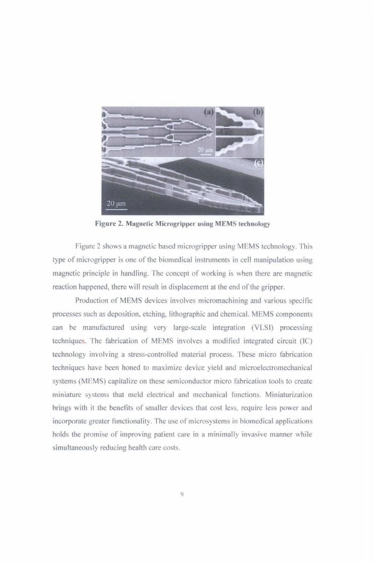
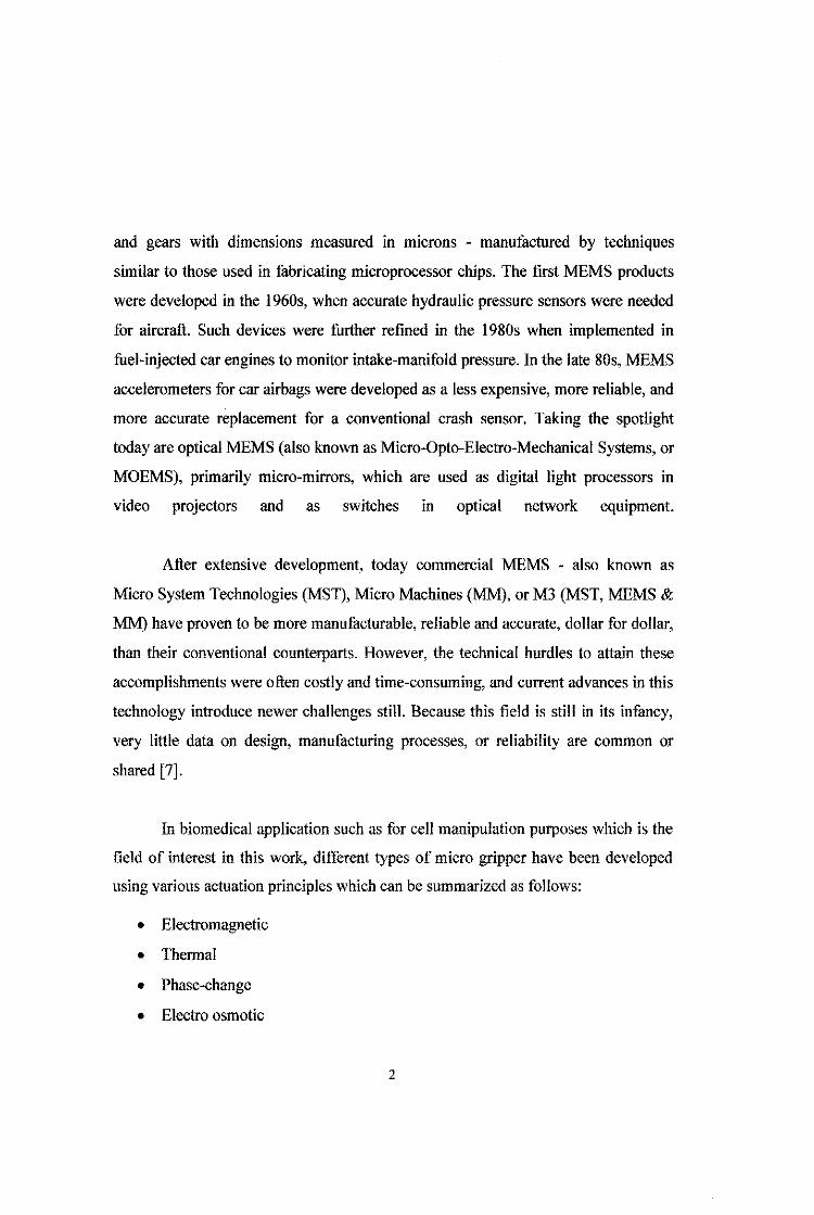
Figure 2. Magnetic Microgripper using MEMS technology
f-igure 2 shows a magnetic based microgripper using MEMS technology. This
t) pe of microgripper is one of the biomedical instrument<. in cell manipulation using
magnetic principle in handling. The concept of working is when there are magnetic
reaction happened, there will result in displacement at the end of the gripper.
Production of MEMS devices involves micromachining and various specific
processes such as deposition, etching, lithographic and chemical. MEMS components
can be manufactured using very large-scale integration (VLSI) processing
techniques. The fabrication of MEM~ im·olves a modified integrated circuit (lC)
technology involving a stress-controlled material process. I hesc micro fabrication
techniques have been honed to maximize device yield and microelectromechanical
systems (MEMS) capitalize on these semiconductor m1cro fabrication tool<; to create
miniature sy<>tem<; that meld electrical and mechanical functions. Miniaturintion
brings with it the benefits or smaller devices that cost less. require less power and
incorporate greater functionality. The use ofmicrosystems in biomedical applications
hold.., the promise of improving patient care in a minimally inva<>ive manner while
simultaneously reducing health care costs.
9

2.2.1 CMOS-MEMS
Fusion of microelectromechanical systems (MFMS) technology with
complementary metal-oxide semiconductor (CMOS) LSI technology is a promising
way to develop highly functional devices beyond CMOS scaling. We have been
developing the integrated CMOS-MEMS technology that fabricates MEMS devices
on a silicon wafer. The integrated CMOS-MEMS technology features
miniaturization, which leads to a thinner. a more high-functionality, high accuracy,
mass-production, not only obtaining high functionality of CMOS circuitry and higher
performance of MEMS devices. Not to mention its monolithically capabi lity with
circuits in the same substrates further increase device pertormancc and sensitivity
( 19].
One example of technology using CMOS-MEMS is accelerometers for game
devices and/or automotive vehicles (20]. Figure 3 shows how the technology was
fabricated into a user-friendly device.
I ~
Figure 3. CMOS-MEMS Accelerometer in 3-axis
tO

2.3. MEMS Actuation Methods
Using MEMS technology for microactuator, there are several principles that
exist in some applications. There are magnetic actuation, piezoelectric actuation,
thermal actuation and electrostatic actuation [21].
• Magnetic: Force is induced by a magnetic field application to actuate a
magnetic material. This actuation mechanism is easy to implement at
microscale, but an order of magnitude reduction in the device length
induces a tour orders of magnitude reduction in forces.
• Piezoelectric: A piezoelectric material converts electrical power into
mechanical power via a crystallographic deformation. When there is a
potential difference between two opposite surfaces, it changes its structure
causing shortening, according to the electric field polarity.
• Thermal: Joule effect and materials deformation due to thermal expansion
are the principle mechanism for this type of actuation. With careful choice
of material and geometry, large displacements and forces can be obtained.
• Electrostatic: A Coulomb force is a surface density force applied by an
electrostatic field created between two parallel conductor plates with
different polarity.
For this project, the microactuator with electrostatic based method is
emphasized. Electrostatic actuation is widespread in MEMS because its
flexibility combinations and simplicity. In addition, this actuation mechanism is a
surface volume phenomenon and scaling down the device dimensions enhances
its effects. Other than that, the advantage such as simple fabrication process, less
power consumption, and utilizes small area for the structure are the reason why
electrostatic actuation is best designed for the biomedical applications.
ll

2.4. Electrostatic Driven Micro Actuators
Many MEMS switches use electrostatic actuation [22]. The principle behind
this actuation mode is the use of parallel plate of a capacitor that produced
electrostatic forces developed between elements with a potential difference. Such
forces are a result of Coulomb's law for the force between charged particles.
Electrostatic concept based on parallel plate is illustrated below:
Figure 4. Electrostatic force between two surfaces with different potentials
A simple example is shown in Figure 4. There are two parallel surfaces of
area A. They are separated by a distance d and the medium between them has a
dielectric constant E ,. Then the potential difference, V between them creates an
attractive (electrostatic) force of
(2.1)
The electrostatic force from Equation (2.1) can thus be used to actuate MEMS
structures, as shown in Figure 4. The fixed electrode attracts the moving cantilever
electrode, making it to bend towards the fixed electrode [23].
Figure 5. A curved electrostatic actuator
12

A simple electrostatic actuator in Figure 5 often referred to as curved-electrode. If an
isolation layer is used between the fixed electrode and the cantilever electrode, the
cantilever can roll along the curved surface. The rest of this thesis concerns with the
etiects of electrostatic actuators used tor micro cell manipulation.
2.5. Hela Cell
In biomedical applications of microsystems fall broadly into two categories
diagnostic and therapeutic systems. Diagnostic applications include DNA diagnostics
[24-26], systems on chips [27-29] and cell [30] and molecule [31] sorting.
Therapeutic systems include drug and gene delivery [32-38], tissue augmentation/
repair [39], micro/minimally invasive surgical systems [40, 41] and biocapsules [42,
43].
Medical researchers use laboratory-grown human cel!s to learn the intricacies
of how cells work and test theories about the causes and treatment of diseases. The
cell lines they need are "immortal"-they can grow indefinitely, be frozen for
decades, divided into different batches and shared among scientists. In 1951, a
scientist at Johns Hopkins Hospital in Baltimore, Maryland, created the first
immortal human cell line with a tissue sample taken from a young black woman with
cervical cancer. Those cells, called HeLa cells, quickly became invaluable to medical
research-though their donor remained a mystery for decades.
In order to help the researchers to manipulate the cell, a micro actuator is
designed specifically for this Bela cell. Henrietta's cells were the first immortal
human cells ever grown in culture. This opportunity made the researchers to initiate a
cell manipulation. They were essential to developing the polio vaccine. They went up
in the first space missions to see what would happen to cells in zero gravity. Many
13

scientific landmarks since then have used her cells, including cloning, gene mapping
and in vitro fertilization.
Figure 6. Hela cell structure
Figure 6 shows the Hela cell structure. Some of the characteristics of Hela
cells are these cells are adherent cells meaning that they will stick to the cell culture
flask. the replication or doubling time is 23 hour~ and Hela cells can easily
contaminate other cell lines as it's often difficult to control. In terms of physical
characteristics, the cell size is approximately 2.000 J..Lm-' in volume and the adherent
cell on a slide is 20 J..Lm diameters for I 00,000 cells in a confluent well of a 96
multiwell plate. For cell manipulation purpose, it is recommended that the
manipulator is capable of grasping each individual cell with actuator displacement of
I ~tm during closing to avoid damaging the cell. This requirement will be used in the
design of the proposed electrostatic micro actuator system.
14

CHAPTER 3: METHODOLOGY
3.1 Project Process Flow
Start: Literature Review
DESIGN On paper design of
the structure
SIMULATION inMATLAB
Yes
End: End of project
Feedback
No
Figure 7. Project flow diagram
In this project, the basic knowledge of actuators using electrostatic principles
must be understood prior to designing the structure of the devices starts. Few
references showed the examples of microactuator available at the market. After
complete designing the devices, the project then is proceed by simulating the
perfmmance of the actuators using MATLAB software. The simulation results will
be gathered and the optimization of the device will be performed. The feedback of
15

the design structure with simulation result will be analyzed and the error will be
calculated.
3.2 Design Structure
Before starL~ designing, the input and output of the system should be
detennix1ed in order to view some relations between them. In this case, the actuator
voltage, V and current through the comb fingers, I are the inputs of the actuator
system. Basically, when the input is given to the actuators, the output from the
actuation system should be noted. Therefore, the desired outputs are the electrostatic
force produced by the capacitor, F that resulting the displacement of the end of
gripper, x and as shown in below.
Voltage, V Current, I
Displacement, x Force, F
---f>l{ ACTUATOR J ,
Figure 8. The input-output relation
Before a gripper can be made, the specimen that wanted to be manipulated
should be taken into account. For this project, by focusing on the Hela cells
manipulation, the size of the Hela cell should be the reference in desi!,'l!ing the
actuator to avoid photo damage of the cell during manipulation process. Research
shows that the stiffness ofHela cell should be 8.38xl0"7 Nm-1 [44]. With estimation
of gripping depth applied onto the cell during manipulation is I f!m, the gripping
16

force experienced by the Hela cell will be 0.84 pN. This is one of the criteria that
should be fulfilled in designing the device. Therefore, in order not to harm the cell,
the force at gripper ann should be less than the resonant force of Hela cell. As
mentioned earlier, the size of Hela cell that need to take into consideration in
gripping them is 20 J.lffi. In this case, in order to hold the cell, the gripper should be
able to open the end-gripper at least l flm. This value will be the second reference of
the design device.
3.3 Tools and Equipment required
3.3.1 M_A..TLAB R2007a
The software will be the main tool fur developing the simulation of
the micrometer design in due to its user friendly interface and the amount of
resources available.
17

CHAPTER 4: MICROACTUATOR DESIGN
This chapter covers the design of the electrostatic based microgripper device
that is suitable for Hela cell manipulation. The Microactuator Design consists of the
the structure design and also equations used to predict device performance. CMOS
MEMS electrostatic based microactuator is designed based on MIMOS 0.35J.Lm
CMOS technology. Based on literature review, to operate the microactuator, the
microactuator must be able to operate with gripping depth and force as listed in
Table I below.
Table 1. Desired microaetuator output
Criteria Value Unit
Gripping depth 1.0 J.Lm
Gripping force 0.084 pN
4.1 Microactuator Design
Comb fmger and dual end-gripper operation are used in this project. The
advantage of using the comb fmger structure is its ability to resonate, which allows
relatively high displacements for corresponding small inputs. The device structure
consists of two cantilever beams, two pairs of flexures to support the beam and also
comb fingers that form a parallel plate of capacitors. When actuator voltage is
supplied through the two parallel plates of capacitor, an electrostatic force will be
produced which pull the two plates (rotor and stator) closer. The parallel plates of
capacitor are arranged in alternately with opposite sign of polarity. The illustration of
comb tingers is illustrated in Figure 9.
18

Figure 9. Comb finger illustration (top view)
The combination of certain numbers of parallel plates may produce certain
amount of electrostatic force that sufficient for the !,>ripper to move to the desired
displacement value. In capacitive part, the parameters that influenced the desired
output are the number of parallel plates, 1\f, the tlJickness of the comb finger, t and the
distance between two parallel plates, d. Despite, the air permittivity between the
comb fingers should be taken into consideration. Therefore, the calculation to find
the electrostatic torce, Fe is measured using the equation 4.1.1 as
tV 2
Fe= ns-. d
(4.1.1)
After the electrostatic force being calculated, the springs that attached to the
flexure beams are also calculated to see the flexibility of the design. For this
microactuator, the springs are attached at the beginning of the device and at the end
of gripper am1s so as to hold and preserve the micron-cells size. The illustration in
Figure 10 shows how the springs are attached to the device structure.
19

Figure 10. Springs attachment
The springs constant can be determined using Equation (4.1.2) as
k. F
X
6El [3
( 4.1.2)
In order to measure the springs constant, the rarameters that should be determined
are the flexures width, w, flexures thickness, t, and length of the flexures, I. In spite
of that, the Young Modulus of 165 GPa is used to specify the flexibility of the
sprmgs.
For a normal pair of parallel plates, the resistive force to the plate moving
normally against the stationary plate is caused by the damping pressure between the
two plates. The damping pressure consists of two main components: the component
to cause the viscous flow of air when the air is squeezed out of (or sucked into) the
plate region and that to cause the compression of the air film. Therefore, the force
component related to the viscous flow is referred to as the viscous damping force,
and the force component related to the air compression is referred to as the elastic
20

damping force. If the plate oscillates with a low frequency, or, the plate moves with a
slow speed, the gas film is not compressed appreciably. In this case, the viscous
damping force dominates. lt will be seen later that the viscous force is directly
proportional to the speed of the plate.
On the other hand, if the plate oscillates with a very high frequency, or moves
with a high speed, the gas film is compressed but fails to escape. In this case, the gas
film works like a bellows. Thus, the elastic force dominates. Obviously, the elastic
force is directly proportional to the displacement ofthe plate.
The squeeze damping ratio is then calculated in order to get the dynamic
equation of the device. The value of squeeze damping ratio can be measured using
this formula:
b = 7.2N[1lW3
g3 (4.1.3)
Where 11 is the viscosity of the air, N is the number of comb fingers, w is the width of
capacitor plate, g is the air gap and I is the length of the capacitor plate. With these
information, a microactuator was designed using all the specifications given. The
structure of the device can be seen in different angles as shown in the Figure ll and
Figure 12.
21

Figure 11. 2-Dimension of electrostatic microactuator structure
Figure 12. 3-Dimensioo of Electrostatic microactuator
22

After few trials and error in optimizing the real value of design structure, all
the parameters are then determined. The detailed design is listed in Table 2.
Table 2. Dimension ofthe electrostatic microactuator
Parameter Symbol Value Unit
Number of capacitors N I
150 -
Thickness of a comb finger t 5 Jlm
Width of a comb finger w 1 Jlm
Length of a comb finger I 24 Jlm
Distance between comb d 3 Jlill fingers
Gap of the fingers do 9 Jlm
Length overlap fmger Ia 18 Jlm
Gap between gripper jaws Xo 20 Jlill
Spring length Is 100 Jlm
Spring thickness fs 50 flill
23
Spring width Ws
I 3 ~m
S iii con density Psi 2330 Kg/m3
Silicon Young's modulus Esi 165 GPa
Aluminum density PAl 2700 Kg/m3
Permittivity of air £0 8.85 X 10'12 Flm
24

CHAPTER 5: RESULTS & DISCUSSION
This chapter discusses on the results obtained from this project. There are two
main sections which are simulation results of the optimized structure and also the
optimization process results. Both are simulated using MA TLAB software.
5.1 Simulation Results of the Structure
All the optimized parameters were listed in Table 3. They were calculated
using the formula attached in Chapter 4 and the graphs are analysed. However, the
desired displacement of 1 J.lm is still maintained.
Table 3. Parameters of the result
Parameter Values Unit
Mass production, m 0.0585 nkg/mj
Spring constant, k 27.844 Nlm
Squeeze damping ratio, b 0.0444 nNs/m"
Electrostatic force, F 10.23 J.!N -
Actuated voltage, V 68 v Number of fingers, N 150 -
The equations then simulated in MATLAB R2010a to produce the following
results on how each changes in actuator voltage supplied will affect the electrostatic
forces produced for the gripper to open the jaw of the actuator.
25
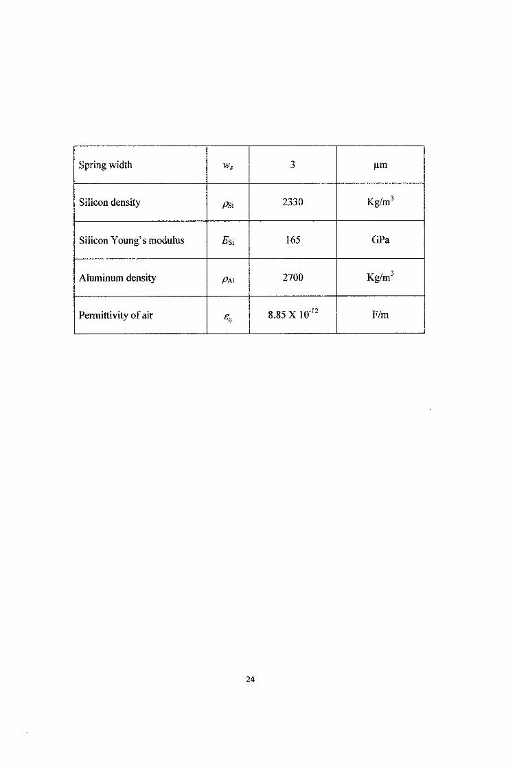
From the results, we found that the sensitivity of the displacement of the
device that the total numbers of comb lingers pairs are suitable for this stmcture by
referring to other structures that based their results on the values of micro ranges. The
simulation was done step by step to find the relations between the parameters as the
input and the mechanical outcome as the output of the device.
Figure 13. Graph of Electrostatic Force versus Voltage
Based on the graph in Figure 13, the relationship between actuator voltage
and the electrostatic force produced by 150 pairs of capacitor is analyzed. For the
range of 0 - 200 V supplied to the systems. the electrostatic force experienced by the
actuator will be in the range of 0- 8 x l0-4 N.
From the graph, we can say that as the actuator voltage increases, the
electrostatic tbrce increases. The graph looks like a positive part of quadratic curve
due to the equation used as in the Equation (4.!.1). A MATLAB coding was run in
order to get the sensitivity of the structure. The sensitivity of the graph is found to be
26
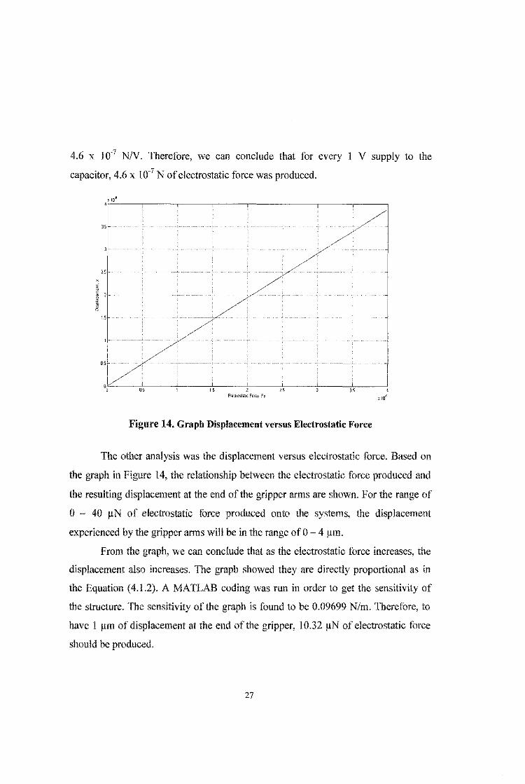
4.6 x 10·7 N!V. Therefore, we can conclude that for every 1 V supply to the
capacitor, 4.6 x 1 o-7 N of electrostatic force was produced.
~ 10~ ·~----.-----------~----.-----,-----,-----,-----,
3.5
/..5
}. 25 Erowoot;;bc Fc-rce, Fe
Figure 14. Graph Displacement versus Electrostatic Force
The other analysis was the displacement versus electrostatic force. Based on
the graph in Figure 14, the relationship between the electrostatic force produced and
the resulting displacement at the end of the gripper arms are shown. For the range of
0 - 40 ~N of electrostatic force produced onto the systems, the displacement
experienced by the gripper arms will be in the range of 0-4 J.UTI.
From the graph, we can conclude that as the electrostatic force increases, the
displacement also increases. TI1e graph showed they are directly proportional as in
the Equation ( 4.1.2). A MATLAB coding was run in order to get the sensitivity of
the structure. The sensitivity of the graph is found to be 0.09699 N/m. Therefore, to
have 1 ~m of displacement at the end of the gripper, 10.32 11N of electrostatic f()!·ce
should be produced.
27

X 10.6
4~-----------,-------------.-------------,
3.5
3
x_ 2.5 E • ~ 2 u ro
c_
6 1.5
05
Voltage, V
Figure 15. Graph Displacement versus Voltage
The displacement versus the applied voltage was also investigated. Based on
the graph in Figure 15, the relationship between the actuator voltage supply and the
resulting displacement at the end of the gripper mms are shown. For the range of
0- 150 V of actuator voltage supply onto the systems, the displacement experienced
by the gripper arms will be in the range of 0-4 1-un.
From the graph, we can say that as the voltage supply increases, the
displacement is also increases. The graph looks like a positive part of quadratic curve
due to the equation used as in the combination of Equation ( 4 .l.l) and Equation
(4.l.2). A MATLAB coding was run in order to get the sensitivity of the structure.
The sensitivity of the graph is 3.26 x 10·8 VIm. Therefore, we can say that every I V
voltage supply, it is resulting 0.0326 run of displacement at the end of the gripper.
28

'"
Figure 16. Dynamic in time response function
Next, the dynamic response of the actuator was analyzed. Based on the graph
m Figure 16, we can see how the reactions of the device dynamically in time
response function. The graph showed that the system is not stable by referring to the
oscillatory output between I - 14 seconds. The time taken for the system to be stable
(or settling down) is approximately 14- 15 seconds, as we take displacement of l~m
as the reference input.
However, the frequency of the arms to be in initial position can be improved.
This process will help the cell manipulation can be done in a short period of time.
Some of the parameters listed can be manipulated in order to get the best output.
29
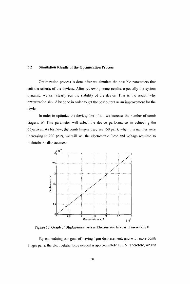
5.2 Simulation Results of the Optimization Process
Optimization process is done after we simulate the possible parameters that
suit the criteria of the devices. After reviewing some results, especially the system
dynamic, we can clearly see the stability of the device. That is the reason why
optimization should be done in order to get the best output as an improvement for the
device.
In order to optimize the device, first of all, we increase the number of comb
fingers, N. This parameter will affect the device performance in achieving the
objectives. As for now, the comb fingers used are 150 pairs, when this number were
increasing to 200 pairs, we will see the electrostatic force and voltage required to
maintain the displacement.
2.5
2 • ,,. ~ ~ 1.5 • 0. • i5
2 2.5 Electrostatic force, F
Figure 17. Graph of Displacement versus Electrostatic force with increasing N
By maintaining our goal of having 111m displacement, and with more comb
finger pairs, the electrostatic force needed is approximately 10 11N. Therefore, we can
30

say that when more parallel plates were used, the more electrostatic force was
produced to move. Since we have lots of comb fingers, the affect of varying actuator
voltage supply to the systems, as illustrated in Figure 18.
2.5 ..
2
E
~ 15 . u . 0 Q.
• i5
0.5 . . ...
0o 10 20 30 40 50 60 70 80 90 100 Voltage, V
Figure 18. Graph of Displacement versus voltage with increasing N
As for the device performance before, with 150 pairs of parallel plates, only
68 V actuator voltages are required to meet the objectives. When optimization
process was done, it shows that if the number of capacitor increasing to 200 pairs, the
actuator voltage should be 58 V.
The conclusion for this is increasing number of comb fingers will increase in
electrostatic force, and thus the actuator voltage should be reduced in order to have a
fixed displacement of I t.tm at the end of the gripper. In addition, it is an advantage
for a device to operate in low voltages as this still has the same output that we want.
When we increase the number of parallel plate, N, the squeeze damping ratio,
b will also increase by referring to the equation (4.1.3). The numbers of comb fingers
31

are directly proportional to the squeeze damping ratio. As the ratio is related to the
dynamic of the device, the changes of the performance was plotted.
Time (s)
Figure 19. Dynamic system of microactuator with increasing damping ratio, b
Figure 19 shows the system dynamic after the effect of increasing number of
fingers thus increase the damping ratio. These changes affect the system stability.
The system is less oscillatory and time taken for the system to be stable is
approximately \\second.
The system should have less settling time and overshoot. As for this case, the
dynamic is better than the one in Figure 16. In order to improve the system
dynamically, the value of spring constant is changed to see their performance.
32

" Time{s)
Figure 20. Dynamic system of microactuator with decreasing constant, k
The dynamic of the microactuator for this project with decreasing constant, k
can be seen in Figure 20. To decrease the value of spring constant, we may increase
the length of the spring, /, and the width of the beam, w. The equation used for this
part is equation ( 4.1.2).
To compare, there is little difference in the oscillatory pattern from the
previous one. It is less oscillatory compared to the graph in Figure 19. However, time
taken for the actuator to be at initial position is still at II seconds. The optimized
parameters are listed in Table 4.
33

Table 4. Optimized parameters
Parameter Values Unit
Mass production, m 0.0585 nkg/mJ
Spring constant, k 7.7344 N/m
Squeeze damping ratio, b 0.0592 nNs/m2
Electrostatic force, F 9.9238 !!N
Actuated voltage, V 58 v Number of fingers, N 200 -
34

CHAPTER6
CONCLUSION AND RECOMMENDATIONS
6.1 Conclusion
By researching the characteristics of Hela cells and technology in MEMS
family, we decided in designing a microactuator using the electrostatic principle for
biomedical use. Basically, the electrostatic based microactuator uses numbers of
comb-drive parallel plate with potential difference and motion produced an
electrostatic field.
The ability of the microactuator is they manage to grip the cell with I 11m
displacement and supply 0.084 pN gripping force onto the cell. From the results, we
can say that the gripper use low voltage which is 58 V and 9.9238 f!N of electrostatic
force to get displacement of I f!m. Other than that it has settling time of II seconds.
The device is optimized by increasing the number of comb fingers, N, then
resulting the increasing of squeeze damping ratio, b. The system is still unstable with
less settling time. Logically, the springs that support the beam should be decreased in
order to have suitable spring length, I.
6.2 Recommendations
There are a few recommendations that can be done to improve this project:
• Varying the variables number of fingers, spring constant and the damping
ratio.
• Simulate the design structure using dedicated ConventorWare software to
clearly see the device performance mechanically.
35

REFERENCES
[1] James J. Paulsen, Joseph M. Giachino, " Powertrain Sensors and Actuators:
Driving Toward Optimized Vehicle Perormance", pp. 575.
[2] Hartmut Janocha, "Microactuators", Actuators: basics and principle, Springer
2004, pp. 320.
[3] Jacek F. Gieras, "Microelectromechanical system", Advancements in electric
machines, Springer 2008, pp. 13.
[4] B.A Parviz, T.-K Allen Chou, C. Zhang, K. Najafi, M.O. Muller, P.D
Washabaugh, L.P. Bernal, "Performance of ultrasonic electrostatic resonators
for use in micro propulsion," The 14th IEEE International Coriference on
Micro Electro Mechanical Systems, Interlaken Switzerland 2001, pp. 586-
589.
[5] G. Galambos, et at., "A Surface Micromachined Electrostatic Drop Ejector,"
Proceedings of transducers '01. lith Conference on Solid- State Sensors and
Actuators, Munich, Germany, June 10-14,2001, pp. 906-909.
[6] S. Kamisuki, et at., "A High Resolution, Electrostatically Driven Commercial
Inkjet Head," Proceedings of MEMS '00, 13th IEEE Workshop on Micro
Electromecanical System, Miyazaci Japan, Jan.23- 27, 2000, pp. 793-798.
36

[7] Gary Sunada, "MicroEiectroMechanical (MEMS)", START: Selected
Technology Assurance Research Technology, 2001 Volume 8, Number I, pp.
I.
[8] Biyovraj Sahu, Curtis R. Taylor, Kam K. Leang, "Emerging Chalengges of
Microactuatorsfor Nanoscale positioning, Assembly, and Manipulation", 21
August 2010.
[9] Sardan, 0., Eichhorn, V., Petersen, D. H., Fatikow, S., Sigmund, 0., and
Boggild, P., 2008, "Rapid Prototyping of Nanotube-Based Devices Using
Topology-Optimized Microgrippers," Nanotechnology, 19(49), p. 495503.
[I 0] Kimberly, T., Matthew, E., Aaron, G., George, S., and Phil, F., 2004, "FIB
Prepared TEM Sample Lift-Out Using MEMS Grippers," Microsc.
Microanal., 10, (S02), pp. 1144-1145.
[II] Chronis, N., and Lee, L. P., 2005, "Eiectrothermally Activated SU-8
Microgripper for Single Cell Manipulation in Solution," J. Microelectromech.
Syst., 14(4), pp. 857-863.
[12] Kim, K., Liu, X., Zhang, Y., and Sun, Y., 2008, "Nanonewton Force
Controlled Manipulation of Biological Cells Using a Monolithic MEMS
Microgripper With Two-Axis Force Feedback," J. Micromech. Microeng.,
18(5), p. 055013.
[13] Requicha, A. A. G., 2003, "Nanorobots, NEMS, and Nanoassembly," Proc.
IEEE, 9, pp. 1922-1933.
37

[ 14] B. E. Volland et al., "Electrostatically driven microgripper", Microelectron.
Eng 61/62 (2002), pp. 1015-1023.
[15] I. P. F. Harouche and C. Shafai, "Simulation of shaped comb drive as a
stepped actuator for microtweezers application", Sens. Actuators, A 123-124
(2005), pp. 540-546.
[ 16] RD Isaac, "The Future of CMOS Technology", IBM Journal of Research and
Development, 2000, pp I - 3.
[17] Baker, R. Jacob (2008). CMOS: circuit design, layout, and
simulation (Seconded.). Wiley-IEEE. p. xxix.
[ 18] Mikael Sterner, "Numerical Algorithms and their Application to MEMS
Electrostatic Actuators", Master's Degree Project in Electrical Measurement
Technology, 2006, pp 3-4.
[19] Hiroki Morimura, Shinichiro Mutoh, Hiromu Ishii, Katsuyuki Machida,
"Integrated CMOS-MEMS Technology and Its Applications", 9th
International Conference, pp. 2460-2463.
[20] R.H. Grace, "Semiconductor Sensors and Microstructures in Automotive
Applications, Sensors and Actuators", Society of Automotive Engineers
International Conference Proceedings, 1991, pp. 245-260.
38

[21] F. Najar, "Static and Dynamic Behaviour of MEMS Microactuators",
National Engineering School of Tunisia, 2008, pp. 7-8.
[22] Y. Nemirovsky and 0. Bochobza-Degani, "A methodology and model for the
pull-in parameters of electrostatic actuators," Journal of
Microelectromechanical Systems, vol. 10, no. 4, pp. 601-615, December
2001.
[23] E. S. Hung and S. D. Senturia, "Extending the travel range of analog-tuned
electrostatic actuators," Journal of Microelectromechanical Systems, vol. 8,
no. 4, pp. 497-505, December 1999.
[24] C.H. Mastrangelo, M.A. Burns, and D.T. Burke, "Microfabricated devices for
genetic diagnostics," Proc .. IEEE, 86(8): 1769-1787 ( 1998).
[25] M.U. Kopp, A.J. de Mello, and A. Manz, "Chemical amplification:
continuos-tlow PCR on a chip," Science, 280: 1046-1048 (1998).
[26] M.A. Northrup, M.T. Ching, R.M.White, and R.T. Watson, "DNA
amplification with a microfabricated reaction chamber," Proc. Int. Conf
Solid-State Sensors and Actuators (Tranducers 93), June 1993, pp. 924-926.
[27] E.T. Lagally, P.C. Simpson, and R.A. Mathies, "Monolithic integrated
microtluidic DNA amplification and capillary electrophoresis analysis
system," Sensors and Actuators B, 63: 138-146 (2000).
[28] J.R. Webster, M.A. Burns, D.T. Burke and C.H. Mastrangelo, "Monolithic
capillary electrophoresis device with integrated tluorescence detector," Anal.
Chern., 73: 1622-1626 (2001).
39

[29] M.A. Burns, B.N. Johnson, S.N. Brahmasandra, K. Handique, J.R. Webster,
M. Krishnan, T.S. Sammarco, P.M. Man, D. Jones, D. Heldsinger, C.H.
Mastrangelo and D.T. Burke, "An integrated nanoliter DNA analysis device,"
Science, 282: 484-487 (1998).
[30] R.H. Carlson, C.V. Gabel, S.S Chan, R.H. Austin, J.P. Brody and J.W.
Winkelman, "Self-sotting of white blood cells in a lattice," Phys. Rev. Lett.,
79(11): 2149-2152 (1997).
[31] T.A.J. Duke and R.H. Austin, "Microfabricated sieve for the continous
sorting af macromolecules," Phys. Rev. Lett., 80(7): 1552-1555 (1998).
[32] J.T. Santini, Jr., M.J. Cima and R. Langer, "A controlled-release microchip,"
Nature, 397: 335-338 (1999).
[33] S. Henry, D.V. McAllister, M.G. Allen and M.R. Prausnitz, "Micromachined
needles for the transdermal delivery of drugs," Proc. IEEE MEMS 1998, pp.
494-498.
(34] S. Hashmi, P. Ling, G. Hashmi, M. Reed, R. Gaugler and W. Trimmer,
"Genetic transformation of nematodes using arrays of micromechanical
piercing structures," BioTechniques, 199: 766-770 (1995).
(35] M.L. Reed, C. Wu, J. Kneller, S. Watkins, D.A. Vorp, A. Nadeem, L.E.
Weiss, K. Rebello, M. Mescher, A.J. Conrad Smith, W. Rosenblum and M.D.
Feldman, "Micromechanical devices for intravasculardrug delivery," J
Pharma. Sci., 8(11): 1387-1394 (1998).
40

[36] A. Trautman, P. Ruther and O.Paul, "Microneedle arrays fabricated using
suspended etch mask technology combined with fluidic through wafer bias"
Proc. MEMS 2003, Kyoto!, Japan, Jan. 2003, pp. 682-691.
[37] P. Griss and G. Stemme, "Novel, side opened out-of-plane microneedles for
microfluidic transdermal interfacing," Proc. MEMS 2002, Las Vegas, USA,
Jan. 2002, pp. 467-470.
[38] J.G.E. Gardeniers, J.W. Berenschot, M.J. de Boer, Y. Yeshurun, M. Hefetz,
R. van't Oever and A. van den Berg, "Silicon micromachinedhollow
microneedles for transdermalliquid transfer," Proc. MEMS 2002, Las Vegas,
USA, Jan. 2002, pp. 141-144.
[39] R. Dizon, H. Han, A. G. Russell and M. L. Reed, "An ion milling pattern
transfer technique for fabrication of three-dimensional micromechanical
structures," J Microelectromechanical Systems, 2( 4): 151-159 ( 1993).
[40] M. Esashi, "Micro elcetro mechanical systems by bulk silicon
micromachining," Proc. 2"d Int. Symp. Microstructures and Microfabricated
Systems, Electrochem. Soc. (1995), pp. 11-23.
[41] A.E. Guber, N. Giordano, A. Schlislsler, 0. Baldinus, M. Loser and P.
Wieneke. "Nitinol-based microinstruments for endoscopic neurosurgery,"
Actuator 96, 51h Int. Conf New Actuators ( 1996), pp. 375-378.
(42] T. A. Desai, D.J. Hansford, L. KUiinsky, A. H. Nashat, G. Rasi, J. Tu, Y.
Wang, M. Zhang and M. Ferrari, "Nanopore technology for biomedical
applications," J Biomed. Microdevices, 2(1): 11-40 (1999).
41

[43] L. Leoni, and T.A. Desai, "Biotrasport and biocompatibility of nanoporous
biocaplsules," 1" Ann. Int. IEEE-EMBS Special Topic Conf on
Microtechnologies in Medicine & Biology (2000), pp. \\3-117.
[44] NEALE Steven L., OHTAAaron T., HSUHsan-Yin, VALLEY Justin K.,
JAMSHIDI Arash, WU Ming C., "Force versus position profiles of HeLa
cells trapped in phototransistor-based optoelectronic tweezers", Emerging
digital micromirror device based systems and applications, San Jose CA ,
ETATS-UN!S (2009) 2009, vol. 7210 [Note(s): I vol., ].
42

APPENDIX I: MATLAB CODES
Voltage vs. Capacitive Force n 200; e 8.85e-12; t Se-6; d 3e-6; v 0:10:150; F I ln*e*t* lv.'2) I /d); plot lv, F); xlabel('Voltage, V'); ylabel('Electrostatic Force, N'); grid on;
Displacement vs. Capacitive Force v 68; e ~ 8.85e-12; t 5e-6; d 3e-6; n 0:10:200; F I ln*e*t* lv'2) I /d); s SOe-6; E 1.65el1; w le-6; 1 lOOe-6; k IE*W*ISA3))/12*11A3)); X F/k; plotiF,x); xlabel('Electrostatic Force, Fe'); ylabel('Displacement, x'); grid on;
43

Displacement vs. Voltage n ~ 150; e 8.85e-12; t Se- 6; d 3e-6; v 0:10:100; F ((n*e*t*(v.'2))1d); E 1.65ell; w le-6; 1 100e-6; ws= 3e-6; ts~ SOe-6; k ~ IE*ws* (ts'31 I I 12* 11 '31 I; X~ Fl(2*k); plot(v,x); xlabel('Voltage, V'); ylabel('Displacernent, x');
Dynamic of the systems m 5.8534e-11; k 7.7344; b 5.9195e-11; A [0 1
-kim -blml; B [0
1Im]; c [1 0]; D=O;
T 0:0.01:20; % simulation time= 10 seconds U ~ [zeros(1,100),ones(1,1ength(T)-100)]; %no input Y = lsim(A, B, C, D, U, T); %simulate and plot the response (the output) plot(T,Y); %plot the output vs. time grid on;
44