cap (cwrs, and lpis) - europa · vhr prime profile ... 25/02/2011 update of document for the 2011...
TRANSCRIPT
Post: Joint Research Centre, IES - Digital Earth and Reference Data Unit, TP 263, I-21027 Ispra (VA), Italy
Telephone: direct line +39 0332 78 6215 Facsimile: +39 0332 78 6369 E-mail: [email protected] URL: http://www.jrc.ec.europa.eu
JRC/IES/H06/2015/21449
VHR image acquisition specifications
for the CAP checks (CwRS and LPIS QA)
-
VHR profile-based specifications including VHR+ profiles
Campaign 2016
Text highlighted in YELLOW contains changes from 2015
Author: Pär Johan ÅSTRAND Status: V.7.8
Co-authors:
Approved:
Giovanni DI MATTEO, Csaba WIRNHARDT, Juergen BREUNIG Agnieszka WALCZYNSKA, Susanne HAIN, Ansgar KORNHOFF, Edith SIMON Pär Johan ÅSTRAND
Circulation: Internal/Commission, MS Administrations and their contractors, FW contractor/s
Date: 21/11/2015 Int. ref: http://ies-intranet/h04/apps/Chrono/21449.docx

EC-JRC-IES- Digital Earth and Reference Data Unit VHR profile-based specifications
JRC/IES/H06/2015/21449 2
Table Of Contents:
Abbreviations, Acronyms and Terms .......................................................................................... 5
1. Introduction ..................................................................................................................... 7
2. Zones definition .............................................................................................................. 10
3. Acquisition windows ....................................................................................................... 13
4. Feasibility assessment .................................................................................................... 15
5. Acquisition Requests (ARs) ............................................................................................. 17
6. QL (Browse Image) Upload.............................................................................................. 17
7. Validation ....................................................................................................................... 19
8. Ordering ......................................................................................................................... 21
9. Delivery .......................................................................................................................... 21
10. Pricing and Invoicing ....................................................................................................... 23
11. Image data provision to the JRC (image-return) and image access ................................... 24
12. VHR prime and backup profiles ....................................................................................... 27
13. Quality Assurance / Quality Control ................................................................................ 30
14. Risk of satellite failure .................................................................................................... 31
15. JRC responsibles and e-mail addresses ............................................................................ 31
16. References ..................................................................................................................... 32
17. Annexes ......................................................................................................................... 34
List of Figures
Figure 1 - Figure showing structure of this document and the SRS image acquisition process ......................................... 9
Figure 2 - Sample XML metadata file structure (including shape file) ............................................................................. 38
List of Tables
Table 1 - VHR profiles adopted within the CAP checks. ................................................................................................... 28
Table 2 - Off-nadir/elevation angles necessary for the A2. VHR prime profile ................................................................ 29
Table 3 - XML metadata file, 'Image'/’Shape’ sections possible sub-nodes .................................................................... 35
Table 4 - Country list and standard abbreviations ........................................................................................................... 36
Table 5 - Possible values for Provider state ..................................................................................................................... 36
Table 6: Description of XML metadata file specification for ortho data return to JRC by FW contractor/s .................... 39
EC-JRC-IES- Digital Earth and Reference Data Unit VHR profile-based specifications
JRC/IES/H06/2015/21449 3
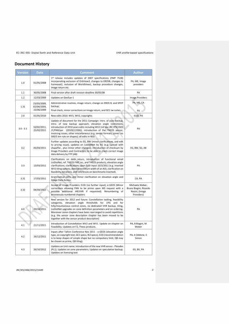
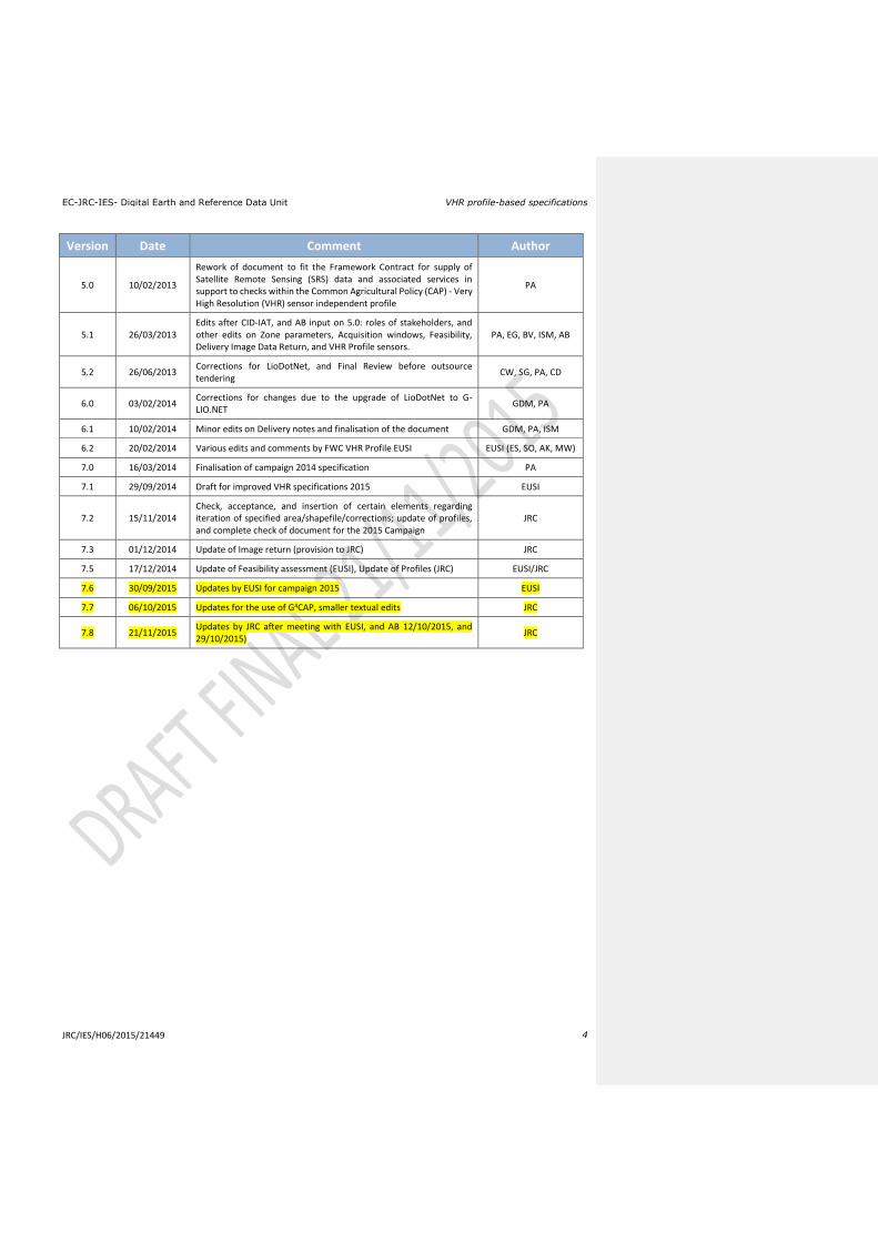
Document History
Version Date Comment Author
1.0 01/05/2008
1st release includes updates of 2007 specifications (FMP 7528) incorporating exclusion of OrbView3, changes to EROSB, changes to Formosat2, inclusion of WorldView1, backup procedure changes, image return etc.
PA, ME, Image providers
1.1 30/05/2008 Final version after draft revision deadline 30/05/08 PA
1.2 12/03/2009 Updates on GeoEye-1 Image Providers
1.31 23/03/2009, 02/04/2009, 22/06/2009
Administrative routines, image return, change on EROS B, and SPOT backup;
Final check, minor corrections on Image return, and GE1 sw suites;
PA, ME, CA
PA
2.0 01/05/2010 New edits 2010: WV1, WV2, copyrights EUSI, PA
3.0 - 3.1 10/02/2011, 25/02/2011
Update of document for the 2011 Campaign: intro. of auto-backup, intro. of new backup approach, elevation angle restrictions, introduction of 2010 years edits including WV2 (ref doc JRC IPSC/G03 /C/PAR/par (2010)(11936)), introduction of the THEOS sensor, invoicing issues, other miscellaneous (e.g. sensor formats, zones: no 500/5 km rule on shapes); all edits in RED.
PA
3.2 05/03/2011
Further updates according to EG, BW (minor clarifications, and edit to pricing issue), updates on LioDotNet by EG (e.g. upload with shapefile , plus minor other changes); introduction of checksum by Image Providers and Contractors to be able to check correct image data delivery by FTP (AB)
EG, BW, SG, AB
3.3 13/03/2011
Clarifications on data return, introduction of functional email LioDotNet, ref. THEOS FWC no., and THEOS products, elevation angle clarifications, clarifications upon EUSI input 10/3/2011 (e.g. inserted WV2 tiling options, deleted minimum width of an AOI, clarification on feasibility iterations, and references on benchmarks inserted).
PA
3.31 17/03/2011 Grammatical edits, and minor clarification on elevation angle and Image Data Access.
CA, PA
3.32 04/04/2011
Accept of Image Providers: EUSI (no further input); e-GEOS (Minor corrections allowing PAN to be prime upon MS request with a possible additional HR/VHR if requested). Renumbering of erroneously numbered chapters
Michaela Weber, Bruno Biagini, Ricardo
Nasini, (Image Providers)
4.0 20/10/2011
New version for 2012 and future: Constellation tasking, feasibility categories, elevation angle thresholds for LPIS and for hilly/mountainous control zones, no dedicated VHR backup, tiling, LioDotNet upgrades on zone definition parameters and on ordering. Moreover some chapters have been rearranged to avoid repetitions (e.g. the sensor zone description chapter has been moved to be together with the sensor product description)
PA
4.1 21/11/2011 Introduction of Constellation WV2 and WV1. Update on chapter on Feasibility. Updates on F2, Theos products.
PA, B Biagini, M Weber
4.2 16/12/2011
Inputs after Tallinn Conference Nov 2011 - e-GEOS (elevation angle typo, on copyright text, GE1 specs, IK2 specs), EUSI (recommendation is to keep shapes of simple shape but no compulsory limit, QB may be chosen as prime, QB tiling).
PA, A Oddone, E Simon
4.3 26/10/2012 Updates on Unit name; Introduction of the new VHR sensor - Pleiades (PL1); Updates on zone parameters; Updates on speculative backup; Updates on licensing text
EG, BV, PA
EC-JRC-IES- Digital Earth and Reference Data Unit VHR profile-based specifications
JRC/IES/H06/2015/21449 4
Version Date Comment Author
5.0 10/02/2013
Rework of document to fit the Framework Contract for supply of Satellite Remote Sensing (SRS) data and associated services in support to checks within the Common Agricultural Policy (CAP) - Very High Resolution (VHR) sensor independent profile
PA
5.1 26/03/2013 Edits after CID-IAT, and AB input on 5.0: roles of stakeholders, and other edits on Zone parameters, Acquisition windows, Feasibility, Delivery Image Data Return, and VHR Profile sensors.
PA, EG, BV, ISM, AB
5.2 26/06/2013 Corrections for LioDotNet, and Final Review before outsource tendering
CW, SG, PA, CD
6.0 03/02/2014 Corrections for changes due to the upgrade of LioDotNet to G-LIO.NET
GDM, PA
6.1 10/02/2014 Minor edits on Delivery notes and finalisation of the document GDM, PA, ISM
6.2 20/02/2014 Various edits and comments by FWC VHR Profile EUSI EUSI (ES, SO, AK, MW)
7.0 16/03/2014 Finalisation of campaign 2014 specification PA
7.1 29/09/2014 Draft for improved VHR specifications 2015 EUSI
7.2 15/11/2014 Check, acceptance, and insertion of certain elements regarding iteration of specified area/shapefile/corrections; update of profiles, and complete check of document for the 2015 Campaign
JRC
7.3 01/12/2014 Update of Image return (provision to JRC) JRC
7.5 17/12/2014 Update of Feasibility assessment (EUSI), Update of Profiles (JRC) EUSI/JRC
7.6 30/09/2015 Updates by EUSI for campaign 2015 EUSI
7.7 06/10/2015 Updates for the use of G4CAP, smaller textual edits JRC
7.8 21/11/2015 Updates by JRC after meeting with EUSI, and AB 12/10/2015, and 29/10/2015)
JRC

EC-JRC-IES- Digital Earth and Reference Data Unit VHR profile-based specifications
JRC/IES/H06/2015/21449 5
Abbreviations, Acronyms and Terms
Abbreviation/Term Explanation
AOI Area Of Interest (of a control zone)
AR(s) Acquisition Request(s)
AR ID Identifier of an Acquisition Request
CA Contracting Authority
CAP Common Agricultural Policy
CAPI Computer Assisted Photo Interpretation
CC Cloud Cover
CfT Call for Tender
CID portal Community Image Data portal
Contractor A Contractor of the MS Administration responsible for the CAP subsidy diagnosis of the MS using the SRS imagery; not to be confused with the Successful Tenderer (ST) of the Framework Contract (FWC) signed in [ref. 6]
COTS Commercial Off-The-Shelf software
CTS Common Technical Specifications
CwRS Control with Remote Sensing
DEM Digital Elevation Model
DG AGRI The Directorate General for Agriculture and Rural Development
DRA Dynamic Range Adjustment
EC European Commission
EC Services in this text: Joint Research Centre of the European Commission
EFA Ecological Focus Area
EPSG European Petroleum Survey Group
EU European Union
EULA End User Licence Agreement
FC(s) Framework Contract(s)
FW contractor/s The successful tenderer who has been awarded a FWC with the EC Services (JRC)
FWC Framework Contract
G4CAP Final evolution of *LIO systems, available from August 2015 on
GAEC Good Agricultural and Environmental Condition (CAP Cross Compliance)
GCP Ground Control Point
GEO/GEOSS Group on Earth Observations / Global Earth Observation System of Systems
GSD Ground Sampling Distance, the nominal size of one sensor pixel projected onto the imaged surface
HR High Resolution (SRS imagery)
IACS Integrated Administration and Control System (CAP)
ICP Independent Check Point (used in ortho image external QC)
ICT Information and Communication Technology
IDQA Input Data Quality Assessment
IES Institute for Environment and Sustainability, Joint Research Centre
INSPIRE Infrastructure for Spatial Information in the European Community

EC-JRC-IES- Digital Earth and Reference Data Unit VHR profile-based specifications
JRC/IES/H06/2015/21449 6
IP(s) Image Provider(s), in this document considered the successful FW contractor/s or successful consortium of Image Providers who has signed a FC with the JRC as of [ref. 6]
IPR Intellectual Property Right(s)
ITT Invitation To Tender
JRC Joint Research Centre of the EC
LD Liquidated Damages
LF Landscape Feature
LioDotNet, G-LIO.NET, NG-LIO.NET, G4CAP
JRC Web-based software for the management of image acquisitions
LPIS Land Parcel Information System
LPIS QA Land Parcel Identification System Quality Assurance
MARS Monitoring Agricultural ResourceS Unit, JRC IES
MS Member State(s)
MS Administration (or its Contractor)
A Contractor of the MS Administration responsible for the CAP subsidy diagnosis of the MS using the SRS imagery.
MS Contractor
Terms used in the CwRS community for a Contractor of the MS Administration responsible for the CAP subsidy diagnosis of the MS using the SRS imagery delivered by this framework contract
MSP Multispectral
OTSC On-The-Spot checks
PAN Panchromatic
PSH Pansharpened
QA Quality Assurance
QC Quality Control
QCR Quality Control Records
QL(s) Quick-Look (s)
RDSI JRC Reference Data and Service Infrastructure
RFV Rapid Field Visit (type of farm inspection under the CAP checks)
RMSE Root Mean Square Error
SEIS Shared Environmental Information System
SMR Statutory Management Requirement (CAP Cross Compliance)
SPS Single Payment Scheme
SRS Satellite Remote Sensing
UTM Universal Transverse Mercator
VHR Very High Resolution (SRS imagery)
WGS 84 World Geodetic System 1985
EC-JRC-IES- Digital Earth and Reference Data Unit VHR profile-based specifications
JRC/IES/H06/2015/21449 7
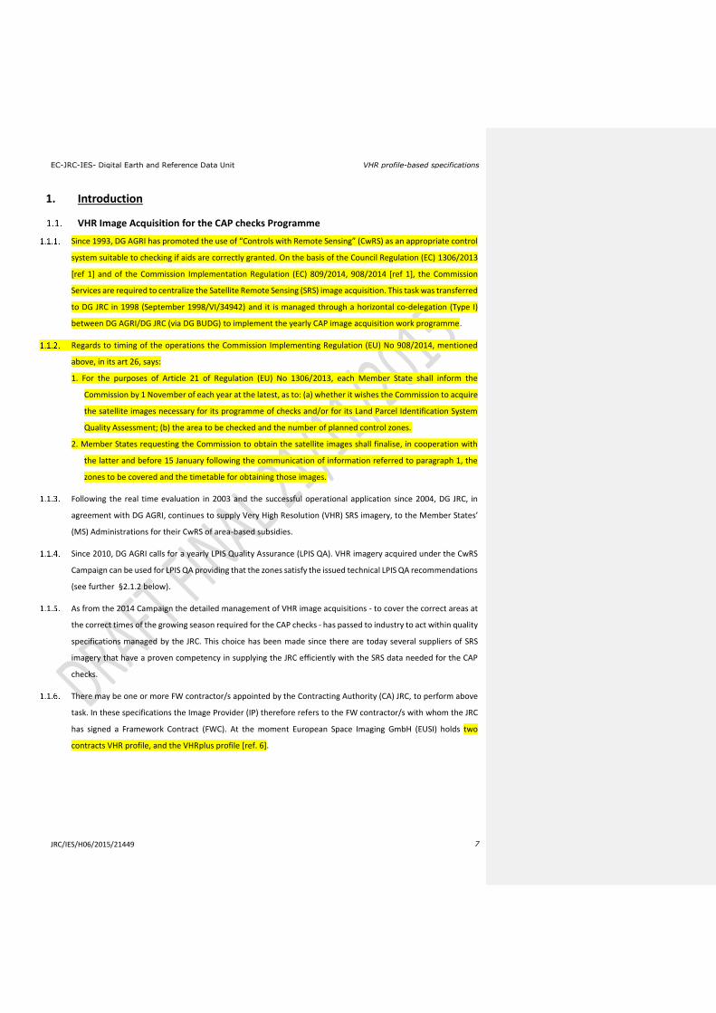
1. Introduction
VHR Image Acquisition for the CAP checks Programme
Since 1993, DG AGRI has promoted the use of “Controls with Remote Sensing” (CwRS) as an appropriate control
system suitable to checking if aids are correctly granted. On the basis of the Council Regulation (EC) 1306/2013
[ref 1] and of the Commission Implementation Regulation (EC) 809/2014, 908/2014 [ref 1], the Commission
Services are required to centralize the Satellite Remote Sensing (SRS) image acquisition. This task was transferred
to DG JRC in 1998 (September 1998/VI/34942) and it is managed through a horizontal co-delegation (Type I)
between DG AGRI/DG JRC (via DG BUDG) to implement the yearly CAP image acquisition work programme.
Regards to timing of the operations the Commission Implementing Regulation (EU) No 908/2014, mentioned
above, in its art 26, says:
1. For the purposes of Article 21 of Regulation (EU) No 1306/2013, each Member State shall inform the
Commission by 1 November of each year at the latest, as to: (a) whether it wishes the Commission to acquire
the satellite images necessary for its programme of checks and/or for its Land Parcel Identification System
Quality Assessment; (b) the area to be checked and the number of planned control zones.
2. Member States requesting the Commission to obtain the satellite images shall finalise, in cooperation with
the latter and before 15 January following the communication of information referred to paragraph 1, the
zones to be covered and the timetable for obtaining those images.
Following the real time evaluation in 2003 and the successful operational application since 2004, DG JRC, in
agreement with DG AGRI, continues to supply Very High Resolution (VHR) SRS imagery, to the Member States’
(MS) Administrations for their CwRS of area-based subsidies.
Since 2010, DG AGRI calls for a yearly LPIS Quality Assurance (LPIS QA). VHR imagery acquired under the CwRS
Campaign can be used for LPIS QA providing that the zones satisfy the issued technical LPIS QA recommendations
(see further §2.1.2 below).
As from the 2014 Campaign the detailed management of VHR image acquisitions - to cover the correct areas at
the correct times of the growing season required for the CAP checks - has passed to industry to act within quality
specifications managed by the JRC. This choice has been made since there are today several suppliers of SRS
imagery that have a proven competency in supplying the JRC efficiently with the SRS data needed for the CAP
checks.
There may be one or more FW contractor/s appointed by the Contracting Authority (CA) JRC, to perform above
task. In these specifications the Image Provider (IP) therefore refers to the FW contractor/s with whom the JRC
has signed a Framework Contract (FWC). At the moment European Space Imaging GmbH (EUSI) holds two
contracts VHR profile, and the VHRplus profile [ref. 6].
EC-JRC-IES- Digital Earth and Reference Data Unit VHR profile-based specifications
JRC/IES/H06/2015/21449 8
1.2. Objectives, referencing and structure of this document
This document constitutes the VHR profile-based specifications to be used within the CAP checks Programme
(CwRS and LPIS QC). Its objective is to give the stakeholders1 in the image acquisition process clarity in the
technical details of the process and describes the process flow starting from zone definition, through the image
use, reaching image return and possible re-use of imagery at end of the Campaign (see Figure 1).
The JRC has an overarching role as responsible for the well-functioning of the framework contracts, and of the
Quality Control (QC) of the operations, while most of the interaction necessary within the image acquisition
process takes place between the FW contractor/s and the MS Administrations (or their Contractor/s performing
the CAP checks). These specifications intend to describe these interactions.
This document is available in the Documentation section of G4CAP Website.
Several references are made here: to the Common Technical Specifications (CTS) for the Remote Sensing
Controls of area-based subsidies [ref. 2]; to the WikiCAP website [ref. 3] for further recommendations; to the
Guidelines for Best Practice and Quality Checking of Ortho Imagery [ref. 4]; to the HR profile-based specifications
[ref. 5] that shall be used in conjunction with the present document. Reference is also made to the terms and
conditions of the Framework Contracts (FWCs) for image procurement to the EC Service [ref. 7].
1 stakeholders, or actors are the JRC, the DG AGRI, the FW Contractor/s acting as image providers and operators and the Member State
(MS) Administrations (or their contractor performing the CAP Checks).
EC-JRC-IES- Digital Earth and Reference Data Unit VHR profile-based specifications
JRC/IES/H06/2015/21449 9
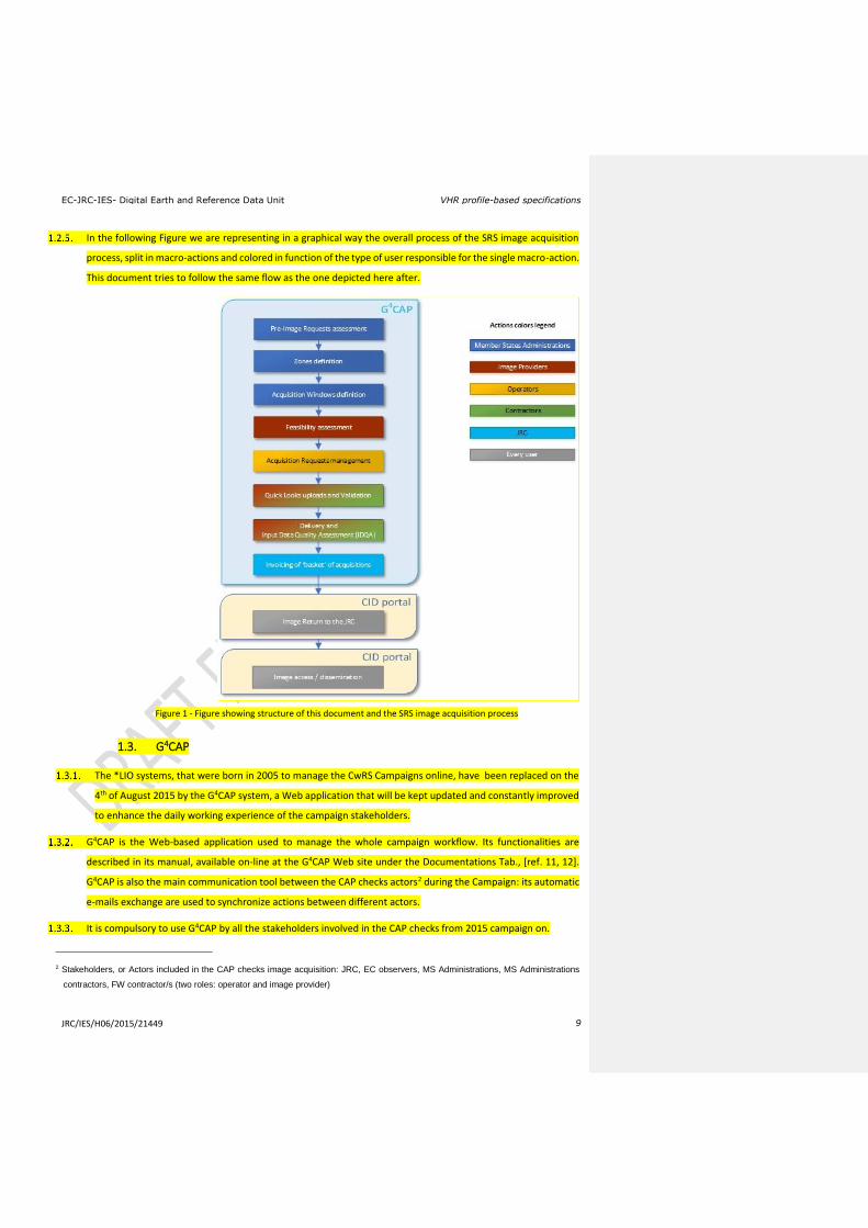
In the following Figure we are representing in a graphical way the overall process of the SRS image acquisition
process, split in macro-actions and colored in function of the type of user responsible for the single macro-action.
This document tries to follow the same flow as the one depicted here after.
Figure 1 - Figure showing structure of this document and the SRS image acquisition process
1.3. G4CAP
The *LIO systems, that were born in 2005 to manage the CwRS Campaigns online, have been replaced on the
4th of August 2015 by the G4CAP system, a Web application that will be kept updated and constantly improved
to enhance the daily working experience of the campaign stakeholders.
G4CAP is the Web-based application used to manage the whole campaign workflow. Its functionalities are
described in its manual, available on-line at the G4CAP Web site under the Documentations Tab., [ref. 11, 12].
G4CAP is also the main communication tool between the CAP checks actors2 during the Campaign: its automatic
e-mails exchange are used to synchronize actions between different actors.
It is compulsory to use G4CAP by all the stakeholders involved in the CAP checks from 2015 campaign on.
2 Stakeholders, or Actors included in the CAP checks image acquisition: JRC, EC observers, MS Administrations, MS Administrations
contractors, FW contractor/s (two roles: operator and image provider)
EC-JRC-IES- Digital Earth and Reference Data Unit VHR profile-based specifications
JRC/IES/H06/2015/21449 10
2. Zones definition
2.1. General
The regulatory basis for the CwRS programme is given in Council Regulation (EC) 1306/2013 (Horizontal Issues),
1307 (Direct Payments)/2013 [ref. 1] and Delegated and Implementing Regulations 639/2014, 640/2014,
641/2014, and 809/14 that allow MS to use remote sensing techniques as a means of carrying out On The Spot
(OTS) checks on agricultural parcels. These are further described in the document “Guidance for on the-spot
checks and area measurement” [ref. 2], which describes that a "control zone" is a geographical area defined on
the basis of GIS analysis, taking account of technical constraints (e.g. standard satellite 'scenes'). These technical
constraints, which are further detailed below, include: swath widths, elevation angles, Area Of Interest (AOI)
definition, window adjustments, feasibility assessment, etc.
Above mentioned Regulation also calls for a yearly LPIS Quality Assurance. VHR Imagery acquired during the
CwRS Campaign can be used for LPIS quality assurance provided that the zones satisfy the technical LPIS QA
recommendations issued, including minimum elevation angle requirements [ref. 3]. MS Administrations not
participating in the CwRS programme can obtain specific acquisitions for LPIS assessment through the EC Services
of the JRC.
The MS Administrations (or their Contractor/s), the FW contractor/s, and the JRC obligatorily need to name one
contact person (or functional e-mail address) to be used for interfacing with each other regarding the issues
listed above and in all other communication during the Campaign.
2.2. Definition of Zone parameters for the Image Request
A CAP control zone (or AOI) consists of a minimum of 4 and a maximum of 999 vertices in Lat/Long Geographic
coordinates (decimal degrees, WGS 84 ellipsoid), represented by a shapefile containing all files with extensions
.shp, .shx, .dbf, .sbx, .sbn, .prj and should be provided by the MS Administration to the FW contractor/s. The MS
Administration should strive to make shape files of simple, regular shapes and to avoid creating too narrow
corridors (e.g. < 5km width since FW contractor/s is not obliged to deliver bigger area to enable a smooth
orthorectification of an image). Zones shapes will be rejected by the JRC if they: (1) overlap within the MS (only
in exceptional cases, e.g. the control schemes/measures over the overlapping area are different and require
separate windows like crops for vineyards, may this be allowed), (2) overlap with adjoining MS borders (this
includes Scotland/England/Wales), (3) cover large amounts of mountainous or other non-agricultural areas; (4)
stretch into coastal waters. There is no regulatory minimum distance between vertices of the shape file. The MS
Administration should however strive to create the simplest suitable zone which shall have a minimum size of
100km².
As imagery is acquired, depending on the sensor’s technical characteristics, the zone is gradually covered entirely
or partially. The FW contractor/s, who is responsible for the implementation of an efficient image acquisition
set-up, always aims to cover the zone in as few acquisitions as possible, but multi-temporal collection is valid if
Commented [PA1]: Could be an idea to have a short chapter describing the LPIS set-up. See otherwise chapter 12.1.3 - enough?
EC-JRC-IES- Digital Earth and Reference Data Unit VHR profile-based specifications
JRC/IES/H06/2015/21449 11
performed within the time limit of the acquisition window. Such multi-temporal acquisitions should be as close
as possible in time since this favors crop interpretation, i.e. “multi-temporality” should be as short as possible.
The MS Administration has to accept a VHR prime profile to be used to cover the zone. The MS Administration
may also accept a VHR backup profile. Both prime and backup profiles will be entered by the MS Administration
as the Image Request is created in G4CAP (see 2.2.10). The FW Contactor will programme accordingly to cover
the control zone efficiently. The FW contractor/s may also propose a backup profile to the MS Administration
whenever he considers it necessary to increase acquisition success during the Campaign and/or to achieve a
positive feasibility result of at least 80%.
The zone may be covered by multiple sensors fitting the prime profile selected by the MS Administration (multi-
sensor and multi-temporal acquisitions are allowed). The FW contractor/s will task the sensors in an optimal
manner to acquire the zone as soon as possible with any of the sensors. It has been proven in earlier Campaigns
that multiple sensor tasking has given an efficiency gain to complete the zone faster, i.e. a reduction of the
acquisition time by adding satellite capacity. Also, even though there will be the possibility of having a zone
completed by more than one sensor fitting to the selected prime profile, it has also been proven that there will
be more chances that a 2nd acquisition is closer in time to the 1st acquisition, i.e. less multi-temporality.
In case a MS Administration accepts a VHR backup profile, a successful backup, if acquired, will be proposed to
the MS Administration (or its Contractor). As long as the MS Administration (or its Contractor) does not accept
this image, the Contractor will continue in an optimal manner to programme the prime profile until the end of
the window. If the MS Administration (or its Contractor) accepts the backup collection, programming of the
prime profile for the relevant zone will be closed. If the window comes to an end without any prime profile
acquisitions (or a partial one only), the MS Administration (or its Contractor) can either accept the backup for
the missing part in case a partial image is available, or ask for further extension of the prime profile. After
maximum extension possible for the MS Administration CAP checks, the MS Administration will need to accept
acquisitions made by either prime or backup. See further under Chapter 3 - Acquisition windows.
When completing any zone, the FW Contractor shall guarantee an overlap (E-W or N-S) between subsequent
acquisitions or strips, of a minimum of 0.5km. Also there shall be an overlap of a minimum of 0.5km between
any partial acquisitions between different sensors. Such overlap is necessary for the orthorectification process.
MS who have selected control zones in a topographically ‘difficult’ terrain shall consider a buffer around their
zones of at least 0.2km (in extreme hilly terrain 0.5km are recommended), depending on topography, to ensure
complete coverage of zone after orthorectification. This is due to the fact that the FW contractor/s delivers Ortho
Ready Standard products that are georeferenced to the average base height of a given area of interest (AOI),
and there could therefore be a horizontal offset for each individual pixel depending on the height difference
between the actual local height of the pixel and average base height of the AOI, which therefore in
orthorectification may cause further “shift” due to topography. It is therefore highly recommended to consider
a sufficient buffer around an AOI to ensure that the AOI is still completely covered with satellite data after

EC-JRC-IES- Digital Earth and Reference Data Unit VHR profile-based specifications
JRC/IES/H06/2015/21449 12
orthorectification. The required buffer (equal to the max horizontal offset) can be calculated as follows, taking
into account the terrain differences inside the AOI, as well as the minimum allowable SatElevation:
[maximum possible height difference of the local height to the average base height of the AOI] / TANGENS
[min allowable SatElevation]
Please take care to calculate the average base height from the height of all pixels inside the AOI (not just taking
highest and lowest height inside the AOI/2).
The VHR zone will be covered either by a bundle product (PAN and MSP as separate bands), or the pansharpened
product, or the PAN only product. If the profile A4 (VHR Stereo) is requested, a stereo product will be delivered.
Special profiles/products may be asked from the JRC; these will allow elevation angle uplift [VHR+ or
Topographic], or [8/16 bands and pan bundle data] (see Chapter 12.1.212.1.212), but MS Administrations will
need to justify such option in detail (in pre-Image Request Module). It is recommended to try to avoid defining
a lot of elevation angle restricted zones to be conglomerated.
All MS Administrations participating in the CAP Checks Campaign insert in the pre-Image Request module of
G4CAP his requests of imagery for the Campaign. These parameters (basic zone parameters) give information
on:
Relevant control method description;
Number of zones and sum area to be acquired (rounded to whole km², UTM) for each type of prime profile
(see Chapter 12.1.2);
Number and type of acquisition windows;
Shapefiles of the control zones (files with extensions .shp, .shx, .dbf, .sbx, .sbn, .prj (Lat/Long, WGS84)).
It is the FW contractor/s responsibility to finalise the remaining parameters (see §2.2.11 below) in its contacts
with the MS Administrations (or their Contractors). The G4CAP web application shall be used also for this purpose
where all relevant parameters shall be inserted in the Zone Definition and Image Requests modules by the MS
Administrations. The FW contractor/s is also responsible for this process and the check on completeness of all
the parameters serving the feasibility assessment (see Chapter 4). When the FW contractor/s has completed this
task, he shall report to the JRC who will validate final results inserted in G4CAP before feasibility analysis starts.
The relevant remaining zone parameters are:
zone name (≤ 5 characters), it needs to be unique for the whole Campaign;
zone (AOI) area (rounded to whole km², UTM) in accordance with the shapefile area handled to the FW
contractor/s by the JRC;
Image request (IR) definition including acquisition windows (from and to dates), and relevant window parameters (e.g. dead period, earliest start date, latest start date, previous window etc., if applicable);
possible VHR backup [see Chapter 12);
product or image mode: bundle or pansharpened, or PAN only;
delivery, DVD, FTP or both.
EC-JRC-IES- Digital Earth and Reference Data Unit VHR profile-based specifications
JRC/IES/H06/2015/21449 13
3. Acquisition windows
There can be either one or two VHR image acquisition windows defined for each CAP control zone. These
windows will be defined by the MS Administrations and will be scheduled suitable for the measurement of the
largest number of agricultural parcels possible. Exact dates will depend on crop cycle and will vary with latitude.
The programming of the second window depends on available budget, and is determined by the JRC at the basic
zone definition stage (see § 2.2.9).
The VHR prime window should be preferably 8 weeks long but never shorter than 6 weeks (42 calendar days).
This statement is valid for the VHR2 windows too. If an HR window is still open, it will close the day before the
VHR prime window opens; also the following HR windows opening will depend on the acquisition of the previous
VHR image. Both these circumstances obligatorily need to be communicated between the VHR and HR FW
contractor/s. Such communication is normally made via G4CAP
When defining the VHR1 and VHR2 windows the MS Administrations shall keep in mind that the final window
might need to be longer, compared to the initial requested one, to make an acquisition feasible. It shall also be
taken into account that may a potential shift of the VHR1 window end date may occur, and care must be taken
that it does not overlap with any subsequent window (HR or VHR). Thus the subsequent window start may need
to be modified.
If extraordinary weather conditions prevail in any region, a window may change (opening and closing dates will
move). This will be dealt with on a case-by-case basis. Such acquisition window dates changes should occur in
very rare cases. Notice shall be given by the MS Administration (or its Contractor) to the FW contractor/s at the
latest 2 weeks before scheduled opening.
It is not useful to open an acquisition window too early in the season as the sun angle is generally low and the
crops may not have developed sufficiently to provide a scene with adequate contrast for a good delineation of
the parcels. It is suggested not to open any window when sun angle is still below 20 deg., in order to ensure
sufficient contrast and to minimize the effect of shadows.
Conversely, this is also true for late start dates of the VHR2 windows, where the sun elevation could drop below
20 degree again.
If a VHR profile sensor (see Chapter 12.1.2) acquires imagery late in the window, the MS Administration may
request an archive search for an earlier HR profile sensor acquisition within the window. In this case the FW
contractor/s shall contact the JRC who will (or will not) give clearance. This obligatorily needs to be
communicated between the FW contractor/s [see §3.1.2].
An acquisition window may be extended if none of the prime or backup profile tasking has successfully acquired
the zone. This will be dealt with on a case-by-case basis. Notice will be given by the MS Administration (or its
Contractor) to the FW contractor/s at the latest 5 working days before window closure. This will allow the FW
contractor/s to continue tasking. Such extensions will be made if crop cycle permits and shall be as long as
possible. The procedure outlined below will apply at window end:

EC-JRC-IES- Digital Earth and Reference Data Unit VHR profile-based specifications
JRC/IES/H06/2015/21449 14
acquisitions outside elevation angle specification or outside Cloud Cover (CC) thresholds may be uploaded
by the FW contractor/s, as proposed, and may be accepted by the MS Administration (or its Contractor);
if above option does not provide enough images to complete the area, the acquisition window can be
extended for the prime and backup VHR profiles. The MS Administration (or its Contractor) will evaluate the
maximum acceptable window extension based on the status of the crop phenology.
Upon request from the JRC, the FW contractor/s shall inform the JRC and the MS Administrations (or its
Contractors) of image acquisition status over the zone (e.g. attempts left before window closure or possible
attempt soon afterwards).
EC-JRC-IES- Digital Earth and Reference Data Unit VHR profile-based specifications
JRC/IES/H06/2015/21449 15
4. Feasibility assessment
The basic zone parameters for the Campaign (see §2.2.9) are received by the FW Contractor/s through the pre-
Image Request module of G4CAP They should be made available to the FW Contractor by the JRC a minimum of
6 weeks before the first window starts. The basic parameters also forms the basis for the relevant specific
contract set up between the JRC and the VHR FW contractor/s. Such contract is a pre-requisite for any feasibility
start.
The FW contractor/s are then responsible (see §2.2.10, §2.2.11) to interact with the MS Administrations (and
their contractors) to finalise the remaining feasibility parameters in G4CAP, and perform the feasibility study. For
these tasks, a timeframe of at least 3 weeks (preferably 4 weeks) should be given to the FW contractor/s.
If necessary (e.g. zones are requested with windows starting earlier than beginning/mid of March) the FW
contractor/s and the JRC can agree on a phased feasibility assessment (e.g. one first feasibility assessment for
the early zones and a second one for all other zones).
A technical and competitive feasibility assessment by the FW contractor/s includes among other things: satellite
characteristics, zone size, zone shape, zone latitude, elevation angle, acquisition window, priority level, CC,
statistical weather forecasting and other competitive tasking requests. All tasking is placed at priority (select
plus) programming.
One of the parameters of the feasibility assessment is the elevation angle. It is well known that a lower elevation
angle puts higher requirements on ancillary data (DEM, GCPs, etc.) to reach orthocorrection accuracy
specification thresholds [ref. 4]. The elevation angle should be kept as high as possible by the FW contractor/s in
order to facilitate orthocorrection.
A higher elevation angle threshold may be requested for certain control zones, e.g. if the control zone is situated
in hilly, or mountainous areas/complex topology (see 12.1.2). The allowed area for such elevation angle uplift
will have been agreed between MS Administration and the JRC prior to the feasibility with the FW contractor/s
as of the Basic Zone parameters §2.2.9.
MS Administrations should bear in mind that they should keep their requests for above elevation angle
restriction to be < 25% of their overall control area. Out of this maximum at most 10% of the total VHR campaign
area (preferably well-distributed for best acquisition success) may have the most severe Elevation Angle and
GSD constraints, following VHR+ topographic profile (A5).
Special profiles such as [A11, A12, A51, A52] 8/16 bands and pan bundle] will be provided depending on
feasibility, and budget availability. They require bilateral agreement with the EC Services.
If the FW contractor/s notice any discrepancy between the areas/parameters as of §2.2.9 given by the JRC and
the areas/parameters inserted in G4CAP by the MS Administration and checked by the FW contractor/s, a final
accept shall be obtained from the JRC before feasibility start.
The feasibility assessment performed by the FW contractor/s shall divide the zones in three categories:
EC-JRC-IES- Digital Earth and Reference Data Unit VHR profile-based specifications
JRC/IES/H06/2015/21449 16
1.) FEASIBLE WITHIN WINDOW (*) - approaching 100% probability;
2.) FEASIBLE WITHIN WINDOW (*) - 80% probability (may need EXTENSION);
3.) NOT FEASIBLE WITHIN WINDOW - with suggestion to make feasible (extend window to…, allow elevation
angle of…) (*).
(*) If the suggestions to make a zone feasible cannot be accepted by the MS Administration, the FW
contractor/s might not accept the zone for tasking, and the MS Administrations must use other means to fulfill
their controls other than the EC provided satellite imagery.
Above feasibility results will require some iteration between the MS Administrations and the FW contractor/s.
This will normally be made during January and February, before the Campaign starts. Extraction of initial and re-
upload of final Image Request is possible via G4CAP.
Finally, an optimum acquisition scenario shall be reached, with clearly defined profiles, zone constraints, final
windows and products to be delivered, etc. This result, completed in G4CAP, and accepted by the MS
Administrations, will be communicated to the JRC for acceptance not later than 2 weeks before the 1st VHR
window opens. In case a phased feasibility assessment is performed (also see §4.1.1), the FW contractor/s and
the JRC can agree on a shorter timeframe to finalize the first feasibility assessment for the early zones (e.g. 1
week before the 1st VHR window of the early zones opens).
EC-JRC-IES- Digital Earth and Reference Data Unit VHR profile-based specifications
JRC/IES/H06/2015/21449 17
5. Acquisition Requests (ARs)
An AR is defined as the implementation by the FW contractor/s of the image requests of the MS Administration
to cover a zone in a specific window with its defined ancillary parameters. An AR is composed of one or more
image acquisitions.
After the feasibility assessment, programming is known, and an AR for the product is opened in G4CAP before
the acquisition window start date is reached. Each AR has a unique identifier called ID.
MS Administration (or its contractors) is notified about windows coming to an end by selecting the specific e-
Mail Selection feature in G4CAP. If no request for the extension of a window is received by the FW Contractor/s,
the window will close at planned closure (window end date).
Preview of uploaded QuickLooks (QLs) is made using the G4QLBrowser (G4QLB) which is an online application for
displaying and browsing QLs and shape files from the image acquisitions. It is reachable directly from within
G4CAP. This tool can also be used by MS Administrations at any time during campaign to check the overall status
of the acquisitions over their Zones for a specific campaign.
6. QL (Browse Image) Upload
The FW contractor/s will notify an acquisition through its upload in the G4CAP system (or e-mail in case of
temporary system unavailability) within 2 working days from the acquisition itself (validated/proposed, or
partial/full upload).
Uploading image acquisition details into the G4CAP starts by clicking on the proper AR; this is done in order to
give the right context to the upload. Image details such as AR ID, Country (ISO name), Zone name, profile,
acquisition date (dd-mm-yyyy), CC (%), haze flag, elevation angle, display order (the display order of the given
layer in G4QLB), provider status (Validated/Proposed/Backup), filename, etc. are defined in the metadata XML3
file. This XML file is compressed in a .zip archive together with QL images, shapefile and other necessary files for
georeferencing and is uploaded into G4CAP.
Upon upload of an acquisition, the G4CAP system will automatically send a dedicated message to interested
actors. Users’ subscriptions to these notifications are managed through the G4CAP system. By default all users
receive this message, unless they deactivate the notification option for this item.
The FW contractor/s’s archives may be consulted by the MS Administrations (or their contractors), as services
are normally free of charge, but subject to subscription. The FW contractor/s will have specific sensors fitting to
the VHR profiles. These will be communicated to the MS Administrations (or their contractors). Archives of these
sensors are included in the EUSI search tool4, the DigitalGlobe Browse Tool5 for QB, WV2, GE1, WV1 and WV3.
3 XML metadata file specification – see Annex 17.1
4 http://www.euspaceimaging.com/imagery-search
5 http://browse.digitalglobe.com/imagefinder

EC-JRC-IES- Digital Earth and Reference Data Unit VHR profile-based specifications
JRC/IES/H06/2015/21449 18
For Kompsat 3 the Arirang search tool can be checked6. The MS Administrations (or their Contractors) may
consult these archives and propose any imagery of the FW contractor/s suitable for their controls activity. The
FW contractor/s will proceed to upload QLs of such imagery into G4CAP for acceptance by the MS
Administrations (or their Contractors).
6 http://arirang.kari.re.kr/
EC-JRC-IES- Digital Earth and Reference Data Unit VHR profile-based specifications
JRC/IES/H06/2015/21449 19
7. Validation
Validation may be performed over the whole zone or over a part of a zone (partial upload, possibly defining an
area to be validated by a vector shapefile. The area to be validated has to be contiguous and should have a
regular and simple shape). It is always done on intersection of the upload (or acquisition) with the zone shapefile.
Every upload (or acquisition) has an acquisition date, is a contiguous area, and has a regular and simple shape.
It is composed of a strip or multiple strips.
For a VHR zone the validation of an upload (or acquisition) is done on the basis of CC content. Haze, which is not
considered cloud by the FW contractor/s, does not cause rejection, but is flagged and may trigger an extra re-
tasking (see §7.1.8). The FW contractor/s uploads georeferenced QLs and relevant XML metadata file, including
CC assessment (following established CC threshold criteria) and haze assessment (haze flag) into G4CAP.
VHR CC thresholds are defined as follows:
a validated acquisition is defined by a maximum CC of ≤ 10% over the AOI. Validation of this imagery does
not require any interaction with the MS Administration (or its Contractor). Validated images are delivered
directly to the MS Administration (or its Contractor) after having passed through Quality Control (QC) of
the FW contractor/s (see §10 and §0);
a proposed acquisition is defined by a 10% < CC ≤ 30% over the AOI. Proposed images are delivered to the
MS Administration (or its Contractor) only upon the MS Administration (or its Contractor) agreement in
G4CAP. Programming continues for better acquisitions during the period of accept/decline which must not
exceed 3 working days. After having been accepted the proposed scene goes through QC of the FW
contractor/s and is shipped to the MS Administration (or it’s Contractor).
Validation of a series of proposed acquisitions (uploads) - the FW contractor/s for the VHR FWCs has agreed to
provide all proposed acquisitions to the MS Administration (or its Contractor) if they accept one proposed
acquisition over the control zone. The MS Administration (or its Contractor) should therefore react within time
limit on proposed acquisition (2 days), and reject if not usable. However, MS Administration (or its Contractor)
needs to keep in mind that when further proposed acquisitions are made available over the same zone, they can
be used together with acquisitions previously rejected by him.
The FW contractor/s will, on a best effort basis, produce regular mosaics of proposed imagery to aid in decision
on usability of series of acquisitions (see §7.1.5). Accepting a series of proposed acquisitions will allow the FW
contractor/s to release satellite capacity for other zones.
Re-upload of a rejected acquisition: the FW contractor/s may re-upload part of a rejected proposed acquisition
if, in combination with a new validated acquisition, it will serve to complete a zone. The re-uploaded proposed
acquisition has to be of validated CC threshold, acquired in one date, be a contiguous area, and has to have a
regular and simple shape.
In case of a conglomeration of CC within part of a large acquisition, this part (minimum 100km²) may be re-
tasked. Even if whole acquisition is validated, the MS Administration (or its Contractor) may ask the FW
EC-JRC-IES- Digital Earth and Reference Data Unit VHR profile-based specifications
JRC/IES/H06/2015/21449 20
contractor/s to perform such re-task. The FW contractor/s will contact the JRC, who will take a decision based
on technical and financial justification. A new zone will be defined for this cloudy part and a new AR will be issued
for this area. The MS Administration (or its Contractor) will follow a procedure similar to the one described in
the section below (haze flag), in order to prove that the re-tasking is required.
A Haze flag is validated as follows:
validated CC upload with flag for dense haze - the flag will trigger an e-mail to the MS Administration (or
its Contractor), who will assess if the dense haze prevents control of the parcels within 3 working days and
provide the FW contractor/s with information regarding the following issues in order for a decision on
possible re-tasking to be taken.
o To prepare a shape file of the control parcel structure (Lat/Long DD WGS 84);
o to assess preliminary T coding due haze (reference CTS [ref ii]);
o to check if any proposed image is available;
o to assess whether the haze image can be used if an atmospheric correction is applied to the
imagery. It should be kept in mind that the image viewed is a QL, which is always inferior in quality
compared to the real source image7.
If the above steps cannot ensure a successful control procedure
o to prepare (possible) new shape file, if not complete zone, to re-collect (minimum 100km²);
o to decide on a new window, and assess the time delay that a re-tasking implies for the success of
the control procedure;
o upon reception of information indicated above from the MS Administration (or its Contractor)
the FW Contactor will contact the JRC who will take a decision on whether to collect additional
imagery (re-task) over part of the control zone based on technical and financial justification.
Proposed CC upload with flag for dense haze - treated as proposed acquisition.
7 The FW contractor/s, may upon request provide final images on FTP for haze evaluation.
EC-JRC-IES- Digital Earth and Reference Data Unit VHR profile-based specifications
JRC/IES/H06/2015/21449 21
8. Ordering
Ordering follows procedures set up in the FWC signed by the FW contractor/s and the JRC [ref. 6]. This is
managed via signature of specific contracts within the FWC.
9. Delivery
Validated partial acquisitions covering a minimum of 100km² contiguous area, and having a regular and simple
shape as defined in §7.1.1 will be delivered in the format and on the media requested. If demanded by the MS
Administration (or its Contractor), the delivery of validated proposed imagery will include all proposed uploads
over the zone.
The contractual delivery period that includes production, internal QC, and ex-works availability is 6 working days
after acquisition for VHR data.
Images (after validation according to procedure in Chapter 7) are delivered directly to the MS Administration (or
its Contractor) after having passed through the internal QC of the FW contractor/s.
The MS Administration (or its Contractor) receives a delivery notification, through G4CAP, as soon as the product
is confirmed as shipped by the FW contractor/s. This delivery notification includes the AR ID and the Acquisition
identifier. If the product is delivered via FTP, G4CAP displays the FTP address, username and password to access
it, else a delivery note is uploaded in G4CAP containing the information on the shipment.
The MS Administration (or its Contractor) must download the product within 8 working days from the day it has
been placed on FTP server by the FW contractor/s.
The FW contractor/s will not only deliver the product to the MS Administration (or its Contractor) on DVD or FTP
as requested, but will also deliver the product to the JRC on specific FTP account for automatic harvest (see §11).
The FW contractor/s will use checksum for correct delivery between FW contractor/s and MS Administration (or
its Contractor), and for image data provision to the JRC (see Chapter 11).
The MS Administration (or its Contractor) will fill in the Input Data Quality Assessment (IDQA) on the acquisition
page of G4CAP within 10 working days after the image has been delivered. This actions will allow the JRC to
obtain Quality Control Records (QCRs) on products, and on delivery performance of the FW contractor/s;
If the MS Administration experiences a delay to nominate its Contractor, he/she will have to perform all
necessary actions by itself. This means that the MS Administration will act as contractor in G4CAP, in order not
to delay delivery, and subsequent invoicing.
The JRC will when above has been performed, set the Acquisition as “ready to be invoiced” and move it to the
“basket” of invoiceable acquisitions.
If the required IDQA is not filled in by the MS Administration (or its Contractor) in 10 working days from delivery
of the imagery, the IDQA state will be assumed to be “accepted” to allow for timely basketification. In these
EC-JRC-IES- Digital Earth and Reference Data Unit VHR profile-based specifications
JRC/IES/H06/2015/21449 22
cases an email will be sent manually by the JRC to the responsible MS Administration placing responsibility of
the Acquisition accept on them in any case.
If in the above IDQA procedure the MS Administration (or its Contractor) notes that the image area delivered8
does not match with the area the FW contractor/s has stated, he will enter his measured area in G4CAP. JRC will
have a final validation role on non-compliances.
An AR is closed only after the whole area has been imaged and the acquisitions have been accepted through
IDQA by the Contractor (unless other circumstance cause closure, e.g. window comes to an end).
If IDQA is not satisfactory for any other reason, the FW contractor/s and the MS Administration (or its Contractor)
shall solve the situation bilaterally by either an acceptance of the MS Administration (or its Contractor), or a
partial or complete re-task by the FW contractor/s. If no agreement is reached the FW contractor/s will report
to the JRC, who has final decisive role on what action to undertake. Relevant provisions of the FWC [ref. vii] shall
apply.
Upon request from the JRC, the FW contractor/s will inform status of image production/QC status (production
pending, production finished, and production date) at any time of the Campaign.
8 calculated (rounded to whole km²) as the intersection between validated acquisition (using final ephemeris data) with the zone in
geographic projection UTM/WGS 84.

EC-JRC-IES- Digital Earth and Reference Data Unit VHR profile-based specifications
JRC/IES/H06/2015/21449 23
10. Pricing and Invoicing
10.1. Pricing
Pricing for products will be in accordance with the FWC signed by the FW contractor/s and the JRC [ref. 6].
10.2. Invoicing - the VHR ‘basket’
The FW contractor/s can invoice any single acquisition delivered and that has been accepted (IDQA PASS) by the
MS Administration (or its Contractor) and that JRC thereafter has set to the status “ready to be invoiced”. G4CAP
will at this point move the acquisition to the “VHR basket” of invoiceable acquisitions.
Such invoicing shall normally be made cumulatively once per month, according to the rules established in the
FWC signed by the FW contractor/s and the JRC [ref. 6]. The identification value for an acquisition to be invoiced
is the AcqId displayed in the basket.
If accepted and delivered imagery turns out to be inadequate, relevant provisions of the FWC shall apply [ref. 6],
where FW contractor/s image warranty applies.
EC-JRC-IES- Digital Earth and Reference Data Unit VHR profile-based specifications
JRC/IES/H06/2015/21449 24
11. Image data provision to the JRC (image-return) and image access
11.1. Image-return to the JRC by FW contractor/s
The FW contractor/s shall provide the SRS image data to JRC for incorporation into the CID Image Portal. This
data provision shall cover the source SRS data as well as orthorectified data, derived from the source data that
are created and processed by the MS Administrations (or their Contractors).
The source data shall be made available to JRC by the FW contractor/s directly after data acquisition with
minimum delay, contemporaneously with the data provision to Member States and their Contractors.
The FW contractor/s shall also collect the orthorectified data at the end of every Campaign from the MS
Administrations (and/or their Contractors) on behalf of JRC and provide them to JRC. The deadline for this data
collection is at the end of the control Campaign year (i.e. 31st December of each year for CwRS), and 31st of
January of the year after the campaign for LPIS QA). The FW Contractor has to check the data for correctness
and complete the JRC metadata file (see 11.1.7). Ortho images shall be handed to the FW contractor as soon as
possible once the FTP details for their upload are communicated. The detailed specifications for the
orthorectified data is provided to the FW contractor/s by the JRC. The FW contractor/s shall ensure the
compliance with these specifications by communicating minimum requirements to the MS Administrations (or
their Contractors).
Both source data and orthorectified data shall be provided to the JRC via standard FTP9 protocol. The FW
contractor/s shall set up an FTP service and create a dedicated FTP account for the JRC. The FW contractor/s
shall ensure minimal transfer speeds of the FTP service of 1 Megabytes/s per connection, with a minimum of 4
possible contemporary connections, and guarantee an uptime of the service of at least 99.0 %. The minimum
retention time for data on the FTP server of the FW contractor/s shall be 4 weeks for source data, and 6 weeks
for orthorectified data.
All SRS image data shall be placed on the dedicated FTP account mentioned above and sorted by image type:
The source data shall be placed into the folder “SOURCE”, the orthorectified data shall be placed under the folder
“ORTHO”. A Upon agreement with JRC, the “ORTHO” data can be handed back on a dedicated HDD. It is also
possible to create two separate FTP accounts for source data and orthorectified data.
Below these folders the first sub-division in subfolders shall be based on the MS for which the image data have
been acquired, using the country 2-digit ISO code (ISO 3166-2) of the MS as naming of the subfolders. The next
sub-division level in sub-folders shall be based on the platform name. The next sub-division level (corresponding
to sub-folders) below platform name will be the zone name as defined by JRC during the acquisition process. SRS
image data of an acquisition together with their metadata shall be placed here. If multiple acquisitions exist for
one zone, they shall be placed in subsequent sub-folders under the zone accordingly. All data with their metadata
9 http://en.wikipedia.org/wiki/Ftp

EC-JRC-IES- Digital Earth and Reference Data Unit VHR profile-based specifications
JRC/IES/H06/2015/21449 25
files must be provided in uncompressed and unpackaged files and directories. Packaging data files and
directories into archive formats (like ZIP, RAR, TAR, etc.) is not permitted.
All acquisitions must be accompanied with a metadata XML file, by default named jrc_metadata.xml, describing
minimum metadata homogeneously for any type of sensor. Depending on the data structure a different file
naming convention for the metadata XML file can be mutually agreed if more suitable. This metadata XML file
shall include e.g. the unique acquisition ID, acquisition date/time (ISO format), zone name, platform name, image
files covered by the metadata file, etc. (see link to schema below). The metadata XML file will be of different
format for Source Data and Orthorectified Data. The full specifications of this metadata XML file together with
an XML schema for validation are provided to the FW contractor/s see ref. vii]. The FW contractor/s must ensure
correct XML structure and content of the metadata XML file and validate it against the provided XML schema.
The XML schemas provide sufficient information about required information to be added and some restrictions
of the possible content of the metadata XML files. The XML schema files are available from JRC under the
following locations: 10. It is important that the XML file is placed in the same directory as the scene data..
For the source data:
http://cidportal.jrc.ec.europa.eu/public-tools/schema/image-acquisition/jrc_metadata_vhr_source.xsd
For the ortho data:
http://cidportal.jrc.ec.europa.eu/public-tools/schema/image-acquisition/jrc_metadata_vhr_ortho.xsd
For source data the creation of the metadata XML files lies in the sole responsibility of the FW contractor/s using
the metadata information from their proprietary metadata files and the NG.LIO system, and converting them
into the required metadata XML file structure.
Finally, in order to enable the JRC (and the MS Administrations or their Contractors) to run checks of complete
data transfer, the FW contractor/s shall provide MD5 checksums for every file included in an acquisition. These
MD5 checksums must be added to checksum files named checksum.md5 and placed in the same folder as the
data, referencing all files in that folder. The content and structure of the checksum files must follow the syntax
of the md5sum tool11, using UNIX style line breaks (newline). The creation of the MD5 checksum files must be
performed at the earliest possible stage of the data acquisition workflow.
11.2. Ortho image return by the Member States to the FW contractor
For ortho images returned by the Member States and their contractors the FW contractor/s shall request the
minimum required information from the Member States and their contractors in order to compile the requested
metadata XML file. The information requested from the Member States and their contractors shall include:
- Ortho image file name, - Zone name, - Acquisition id’s (Acq_ID) ,
10 for HR data replace “vhr” with “hr”
11 http://en.wikipedia.org/wiki/Md5sum
EC-JRC-IES- Digital Earth and Reference Data Unit VHR profile-based specifications
JRC/IES/H06/2015/21449 26
- Mission (platform) name and version, - Coordinate reference system as EPSG code and/or WKT, - Band order with respect to the original sensor bands, - Imaging date & time.
Items in bold are essential. Any additional information required for the compilation of the metadata XML files
shall be in the sole responsibility of the FW contractor/s and shall be taken from source image delivery based on
the acquisition batch Id’s. In case it is not clear which data were used to create the ortho images the FW
contractor/s can request this information from the Member States.
Description of the requested image formats of the uncompressed ortho imagery:
a) return images only as GeoTiff (.TIF) or optionally standard Erdas IMAGINE HFA (.IMG) format b) return images with all source bands, in original band order. c) return images in original radiometry (data type, i.e. number of bytes/pixel), without histogram stretching
In case source imagery has been delivered as BUNDLE product, return ortho imagery as a BUNDLE product. In
case source imagery has been delivered as PANSHARPENED product, return ortho imagery as PANSHARPENED
product. If you have created your own pansharpened product, it will be accepted as valid OIR only if it preserves
the original radiometric resolution (i.e. avoid rescaling from 16 bit, (respective 11/12 bit) to 8 bit.) of the
delivered source BUNDLE.
Image mosaics are accepted only if they preserve original radiometric resolution and all bands in original band
order. In case of non-original radiometric resolution and band order, then please return the orthocorrected
image strips as received with original radiometric resolution and including all bands. The mosaic may be returned
as additional product but does not constitute a full OIR.
Generally speaking return imagery, except of the orthorectification, as un-processed as possible, which facilitates
re-use of data for other allowed users.
For ORTHO data where the returned images are a mix of several platforms the XML shall use "SATELLITE" for
<MISSION> since currently an image can only be related to 1 platform/sensor. The <IMAGING_DATE> should
then always be the latest date of all involved images, <IMAGING_TIME> should be "00:00:00" for this mixed
platform/mission data.
11.3. Ortho Image Return to JRC via EUSI
Pls. refer to Annex 17.2 for information on the xml metadata file specification
11.4. VHR Image access
MS Administrations (and their Contractors) may access imagery purchased through the FWC [ref. vii]. This image
access needs to follow principles set up in the licensing agreement between the FW contractor/s and the JRC, as
agreed in the FWC [ref. vii]. An End User License Agreement (EULA) based on the same principles will bind the
users from the moment of their registration to CIDportal [ref viii], or their registration to G4CAP [ref. xii].

EC-JRC-IES- Digital Earth and Reference Data Unit VHR profile-based specifications
JRC/IES/H06/2015/21449 27
In accordance with the EULA, images used in above operations may neither be disseminated nor the resulting
products sold. Image access should be arranged through the CID server of the JRC, Ispra.
The EC Service purchases a limited right of use, but the images themselves remain the property of the FW
contractor/s. In addition, according to the EULA [ref. viii, § 6 on IPRs] imagery must have proper references.
When using the imagery the Licensee needs to refer to the supplier with the exact display of the credits as
specified in the product’s metadata which will take the form:
“© owner or supplier name or mission name (year of acquisition, or validity of Framework Contract), all
rights reserved)”
In addition, the End User should indicate the following information:
“Data received via the Joint Research Centre of the European Commission under FWC xxx.yyy “
where the FWC number is available from the EC Services (JRC)
For the presently running FWC 389.911 [ref. vii] with EUSI the first sentence above shall be substituted with:
- “WorldView-2 data, © European Space Imaging/DigitalGlobe ™, year of acquisition, distributed by
European Space Imaging”
- “WorldView-1 data, © European Space Imaging/DigitalGlobe ™, year of acquisition, distributed by
European Space Imaging”
- “GeoEye-1 data © DigitalGlobe ™, year of acquisition
- “EROS B data, © ImageSat International N.V ™, year of acquisition, distributed by European Space
Imaging”
- “Kompsat 3 data, © Satrec Initiative, provided by European Space Imaging”
- “WorldView3-data, © DigitalGlobe ™, provided by European Space Imaging”
12. VHR prime and backup profiles
As of Campaign 2014 the MS and its contractors can request a sensor independent profile of interest for the
control zone from an available menu of profiles (see Table 1). Each profile is defined by certain parameters and
it is in the FW contractor/s responsibility to coordinate collections and assign the sensors in the most efficient
and suitable way.
A summary of the profile characteristics is given in the table below.
EC-JRC-IES- Digital Earth and Reference Data Unit VHR profile-based specifications
JRC/IES/H06/2015/21449 28
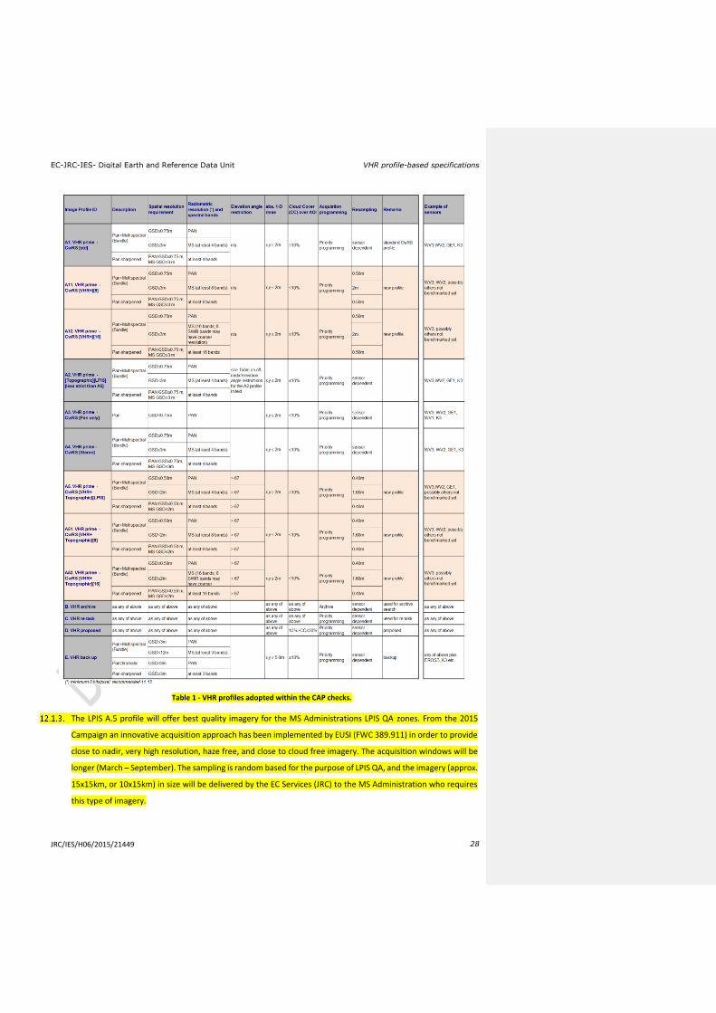
Table 1 - VHR profiles adopted within the CAP checks.
The LPIS A.5 profile will offer best quality imagery for the MS Administrations LPIS QA zones. From the 2015
Campaign an innovative acquisition approach has been implemented by EUSI (FWC 389.911) in order to provide
close to nadir, very high resolution, haze free, and close to cloud free imagery. The acquisition windows will be
longer (March – September). The sampling is random based for the purpose of LPIS QA, and the imagery (approx.
15x15km, or 10x15km) in size will be delivered by the EC Services (JRC) to the MS Administration who requires
this type of imagery.
EC-JRC-IES- Digital Earth and Reference Data Unit VHR profile-based specifications
JRC/IES/H06/2015/21449 29
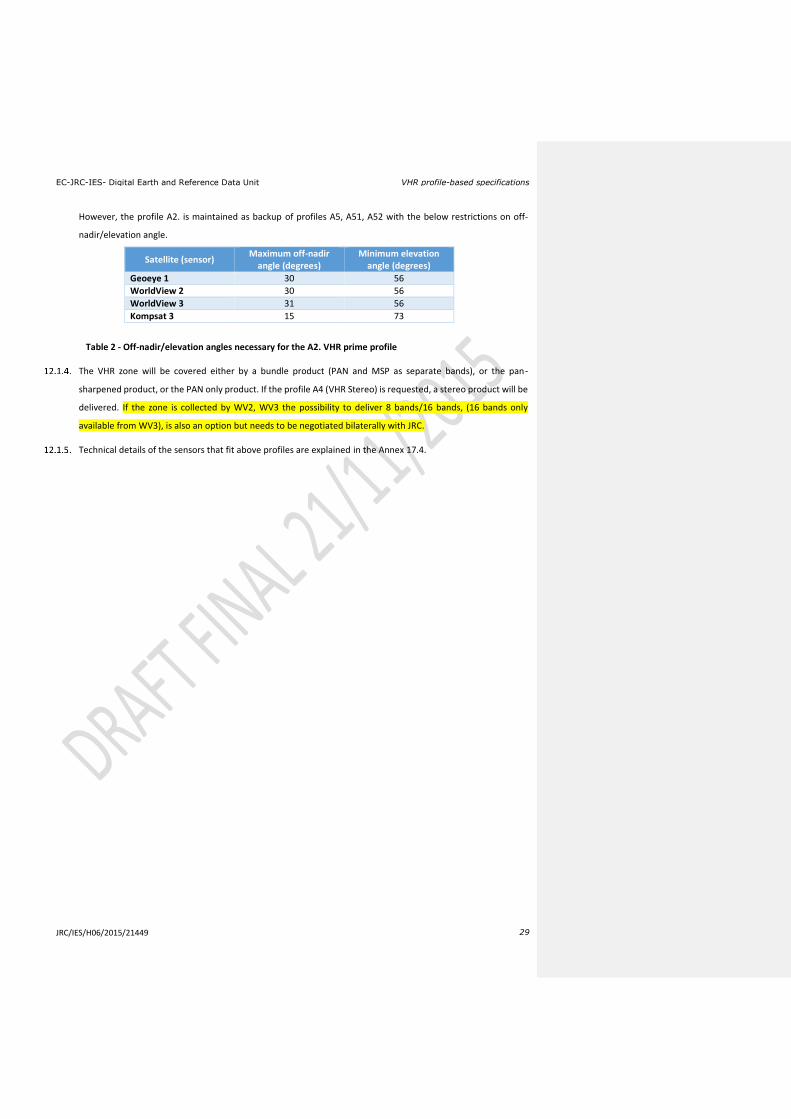
However, the profile A2. is maintained as backup of profiles A5, A51, A52 with the below restrictions on off-
nadir/elevation angle.
Satellite (sensor) Maximum off-nadir
angle (degrees) Minimum elevation
angle (degrees)
Geoeye 1 30 56
WorldView 2 30 56
WorldView 3 31 56
Kompsat 3 15 73
Table 2 - Off-nadir/elevation angles necessary for the A2. VHR prime profile
The VHR zone will be covered either by a bundle product (PAN and MSP as separate bands), or the pan-
sharpened product, or the PAN only product. If the profile A4 (VHR Stereo) is requested, a stereo product will be
delivered. If the zone is collected by WV2, WV3 the possibility to deliver 8 bands/16 bands, (16 bands only
available from WV3), is also an option but needs to be negotiated bilaterally with JRC.
Technical details of the sensors that fit above profiles are explained in the Annex 17.4.

EC-JRC-IES- Digital Earth and Reference Data Unit VHR profile-based specifications
JRC/IES/H06/2015/21449 30
13. Quality Assurance / Quality Control
13.1. Quality Assurance / Quality Control (QA/QC)
The principal objective of the CAP image acquisition is to reach the goal of minimum 95% success rate of image
supply on time, according to specifications. In order to ensure this result an adequate QA/QC needs to be put in
place; the FW contractor/s shall therefore apply a QA and internal QC to the imagery and to the process of
performing image acquisition. Then JRC will have an overarching role in making external Quality Control on the
procedures that the FW contractor/s has set up. This is performed through specific deliverables, QC records
(QCRs), and QC visits throughout the contract running between the FW contractor/s and the JRC [ref. vii].
QA may be defined to be the steps performed in order to ensure that the production of a product meets a set
of accepted standards. QC aims to detect non-conformities in a product.
QC includes assessment of issues such as data integrity, data completeness, CC, haze or thin clouds, cloud
shadows, fog, smoke, smog, snow, flares, etc. It also includes assessing the product geometry, radiometry, image
characteristics (dropouts etc.), and finally the production parameters (resampling algorithm, bit depth), etc.
The FW contractor/s will follow their internally-defined QA/QC procedures on their products including at least
the above mentioned issues. They will deliver a conformal product, or propose a non-conformal product for
evaluation clearly stating reasons for QC failure - such image will be treated as a “proposed” image. A proposed
image can also be e.g. an acquisition at elevation angle below requirement.
13.2. Specificities on Cloud Cover (CC)
Cloud will be defined as white opaque with little or no image information available of the ground features below.
It does not include cloud shadow. Dense haze which causes consistent muting of imagery should be included.
There are different CC assessment routines, e.g.:
a) automatic or semi-automatic thresholding, with subsequent quality factor including issues of dense haze,
haze, smoke, pollution, snow, shadow, etc. A visual observation after classification is required to adjust CC
taking into account issues of dense haze, cloud conglomeration, etc.;
b) manual photo interpretation and subsequent vector digitizing: if a definite boundary between affected
pixels and un-affected pixels is visible it is a cloud.
The JRC decided that imposing of a common CC assessment approach on the FW contractor/s is not efficient.
The CC assessment should result in an agreement between FW contractor/s and the MS Administrations (or their
Contractors) otherwise the FW contractor/s needs to report to the JRC, who has the right to decide.
Both approaches in §13.2.2 are accepted by JRC. The MS Administration (or their Contractors) and the FW
contractor/s should however, in order to arrive to an efficient CAP checks programme with successful outcome,
aim for an optimisation of the image use.
CC validation and haze flagging should follow the procedure described in Chapter 7.

EC-JRC-IES- Digital Earth and Reference Data Unit VHR profile-based specifications
JRC/IES/H06/2015/21449 31
The accuracy to which CC will be performed is to a better than 1% definition.
14. Risk of satellite failure
The FW contractor/s is responsible for communicating any technical problem connected to a satellite sensor, to
the receiving station or to the processing chain as soon as possible to the JRC. This is important in order to limit
risks to the Campaign by allowing switching to other satellite sensors or switching to traditional on-the-spot
checks for the control of the area-based subsidies.
15. JRC responsibles and e-mail addresses
IES / image acquisition
IES / CAP related issues
EC-JRC-IES- Digital Earth and Reference Data Unit VHR profile-based specifications
JRC/IES/H06/2015/21449 32
16. References
1 EUR Lex Access to European Union law: http://eur-lex.europa.eu/homepage.html
2 GUIDANCE FOR ON-THE-SPOT CHECKS AND AREA MEASUREMENT - CLAIM YEAR 2015 http://mars.jrc.ec.europa.eu/mars/content/download/3472/17236/file/DS-2014-32_OTSC%20guidelines%202015%20.pdf – final version (REV 3) will be discussed at the Direct Payment Committee in Brussels on the 9th of December Guidance on Ecological Focus Areas (EFAs):
https://marswiki.jrc.ec.europa.eu/wikicap/index.php/Main_Page
Guidance on Crop Diversification (CD):
https://marswiki.jrc.ec.europa.eu/wikicap/index.php/Main_Page
3 LPIS quality assessment and CwRS imagery used for this assessment (WikiCAP) https://marswiki.jrc.ec.europa.eu/wikicap/index.php/LPIS
4 Guidelines for Best Practice and Quality Checking of Ortho Imagery [Issue 3.0 available at:
http://mars.jrc.ec.europa.eu/mars/News-Events/New-version-of-the-Guidance-for-Best-Practice-and-
Quality-Checking-of-Ortho-Imagery
5 HR ‘profile based’ Specs (ref file://S:\FMPArchive\C\17362.doc)
6 FWCs for satellite image purchase held at the JRC IES:
a. Framework contracts for supply of Satellite Remote Sensing (SRS) data and associated services in
support to checks within the Common Agricultural Policy (CAP); (1) VHR profile tender FWC 389.911
with European Space Imaging GmbH, and (2) HR profile tender FWC 389.912 AirBus Defence and
Space respectively.
b. Framework contract for supply of Satellite Remote Sensing Data; broker (no award as of this
document last edit).
7 The CID portal EULA http://cidportal.jrc.ec.europa.eu/home/idp/licensing/eula
8 Benchmarking GeoEye-1, WorldView-2, GeoEye-1, Cartosat-2, Kompsat-2, RapidEye and THEOS image [JRC
Oral presentation Cat3.4 JRC60286 JRC IPSC/G03/C/JNO/jno D(2010)(12136),Int. ref.
file://S:\FMPArchive\C\12136.ppt - Presented at the MARS Unit’s GEOCAP Action’s Control Methods
Workshop - 2010 Campaign; 13-14 April 2010; Ispra (Italy); Authors: Nowak Da Costa J.K, Åstrand P.J]
a. Nowak Da Costa J, Walczynska A. Evaluating the WorldView-2, GeoEye-1, DMCII, THEOS and KOMPSAT-2 Imagery for use in the Common Agricultural Policy Control with Remote Sensing Programme. Oral presentation in: 16th Conference on `Geomatics in support of the CAP`; 24 November 2010; Bergamo (Italy); GeoCAP Action of the MARS Unit, IPSC, DG JRC (Organiser). 2010. JRC61995
b. PUBSY: http://publications.jrc.ec.europa.eu/repository/
9 Benchmarking Worldview2
a. Nowak Da Costa J, Walczynska A. Evaluating the WorldView-2, GeoEye-1, DMCII, THEOS and KOMPSAT-2 Imagery for use in the Common Agricultural Policy Control with Remote Sensing Programme. Oral presentation in: 16th Conference on `Geomatics in support of the CAP`; 24 November 2010; Bergamo (Italy); GeoCAP Action of the MARS Unit, IPSC, DG JRC (Organiser). 2010. JRC61995
b. Geometric quality analysis of the WorldView2 Basic (level 1A) and OrthoReady (level 2A) images acquired over the JRC MARS Unit’s Maussane Terrestrial Test Site. [JRC Scientific and Technical Report

EC-JRC-IES- Digital Earth and Reference Data Unit VHR profile-based specifications
JRC/IES/H06/2015/21449 33
Cat 2.2, no.24525 EN, ISSN 1018-5593, ISBN 978-92-79-15625, JRC PUBSY Category 2.2, No. JRC60424 file://S:\FMPArchive\C\12126.pdf Authors: Nowak Da Costa, J.K., 2010] – with supplementary Annex post Bergamo Conference PUBSY JRC64624 EUR 24525 EN file://S:\FMPArchive\C\12527.pdf.
c. Further: "Sensitivity analysis of the WorldView-2 satellite orthoimage horizontal accuracy ..." [ref. JRC IES/H04/C/PAR/par D(2011)(13754) file://S:\FMPArchive\C\13754.doc], PUBSY JRC66797.
d. Further:”WorldView-2 potentialities for orthoimage production within the Control with Remote Sensing Programme of the European Commission” [ref. file://S:\FMPArchive\C\13959.doc], PUBSY JRC67516
e. PUBSY: http://publications.jrc.ec.europa.eu/repository/
10 Benchmarking the WorldView-1 and EROS B sensors for use in the Common Agricultural Policy Control
with Remote Sensing programme [PUBSY # JRC49378, Category 3.4 Oral presentation, Available at:
http://mars.jrc.ec.europa.eu/mars/News-Events/MARS-Conference-2008/Agenda-and-
Presentations/T2_Nowak_WV1_EROS2_JRC
11 URL to G4CAP is https://g4cap.jrc.ec.europa.eu
12 G4CAP manual, see under Documents in G4CAP: https://g4cap.jrc.ec.europa.eu
13 Benchmarking Kompsat3; http://mars.jrc.ec.europa.eu/mars/News-Events/20th-MARS-Conference-19-20-November-2014-Dresden-Germany/pres-10
14 Benchmarking on WV3; ongoing reporting to be inserted; Dresden 2014 PPT: http://mars.jrc.ec.europa.eu/mars/News-Events/20th-MARS-Conference-19-20-November-2014-Dresden-Germany/pres-12
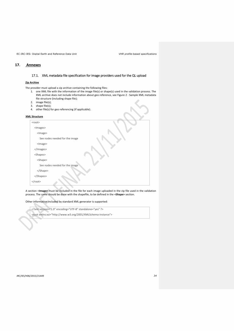
EC-JRC-IES- Digital Earth and Reference Data Unit VHR profile-based specifications
JRC/IES/H06/2015/21449 34
17. Annexes
17.1. XML metadata file specification for image providers used for the QL upload
Zip Archive
The provider must upload a zip archive containing the following files: 1. one XML file with the information of the image file(s) or shape(s) used in the validation process. The
XML archive does not include information about geo reference, see Figure 2 - Sample XML metadata file structure (including shape file);
2. image file(s); 3. shape file(s); 4. other file(s) for geo referencing (if applicable).
XML Structure
<root>
<Images>
<Image>
See nodes needed for the image
<Image>
</Images>
<Shapes>
<Shape>
See nodes needed for the image
</Shape>
</Shapes>
</root>
A section <Image> must be included in the file for each image uploaded in the zip file used in the validation process. The same should be done with the shapefile, to be defined in the <Shape> section. Other information included by standard XML generator is supported:
<?xml version="1.0" encoding="UTF-8" standalone="yes" ?>
<root xmlns:xsi="http://www.w3.org/2001/XMLSchema-instance">
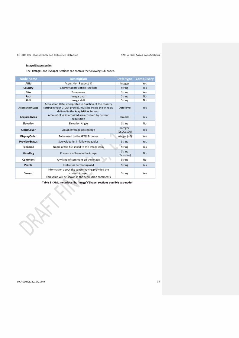
EC-JRC-IES- Digital Earth and Reference Data Unit VHR profile-based specifications
JRC/IES/H06/2015/21449 35
Image/Shape section
The <Image> and <Shape> sections can contain the following sub-nodes.
Node name Description Data type Compulsory ARId Acquisition Request ID Integer Yes
Country Country abbreviation (see list) String Yes
Site Zone name String Yes
Path Image path String No
Shift Image shift String No
AcquisitionDate Acquisition Date, interpreted in function of the country
setting in your G4CAP profile), must be inside the window defined in the Acquisition Request
DateTime Yes
AcquiredArea Amount of valid acquired area covered by current
acquisition Double Yes
Elevation Elevation Angle String No
CloudCover Cloud coverage percentage Integer
(0≤CC≤100) Yes
DisplayOrder To be used by the G4QL Browser Integer (>0) Yes
ProviderStatus See values list in following tables String Yes
Filename Name of the file linked to this Image item String Yes
HazeFlag Presence of haze in the image String
(Yes – No) No
Comment Any kind of comment on the image String No
Profile Profile for current upload String Yes
Sensor Information about the sensor having provided the
current image. This value will be shown in the acquisition comments
String Yes
Table 3 - XML metadata file, 'Image'/’Shape’ sections possible sub-nodes
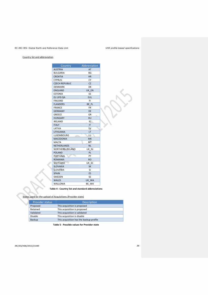
EC-JRC-IES- Digital Earth and Reference Data Unit VHR profile-based specifications
JRC/IES/H06/2015/21449 36
Country list and abbreviation
Country Abbreviation AUSTRIA AT
BULGARIA BG
CROATIA HR
CYPRUS CY
CZECH REPUBLIC CZ
DENMARK DK
ENGLAND UK_EN
ESTONIA EE
EU LPIS QA EUL
FINLAND FI
FLANDERS BE_FL
FRANCE FR
GERMANY DE
GREECE GR
HUNGARY HU
IRELAND IE
ITALY IT
LATVIA LV
LITHUANIA LT
LUXEMBOURG LU
MACEDONIA MK
MALTA MT
NETHERLANDS NL
NORTHERN IRELAND UK_NI
POLAND PL
PORTUGAL PT
ROMANIA RO
SCOTLAND UK_SC
SLOVAKIA SK
SLOVENIA SI
SPAIN ES
SWEDEN SE
WALES UK_WA
WALLONIA BE_WA
Table 4 - Country list and standard abbreviations
States used for the upload of Acquisitions (Provider state)
Provider status Description Proposed This acquisition is proposed
Retained This acquisition is proposed
Validated This acquisition is validated
Disable This acquisition is disable
Backup This acquisition has the backup profile
Table 5 - Possible values for Provider state
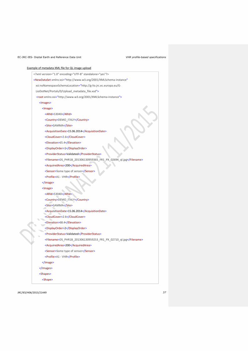
EC-JRC-IES- Digital Earth and Reference Data Unit VHR profile-based specifications
JRC/IES/H06/2015/21449 37
Example of metadata XML file for QL image upload
<?xml version="1.0" encoding="UTF-8" standalone="yes"?>
<NewDataSet xmlns:xsi="http://www.w3.org/2001/XMLSchema-instance"
xsi:noNamespaceSchemaLocation="http://g-lio.jrc.ec.europa.eu/G-
LioDotNet/Portals/0/Upload_metadata_file.xsd">
<root xmlns:xsi="http://www.w3.org/2001/XMLSchema-instance">
<Images>
<Image>
<ARId>53040</ARId>
<Country>DEMO_ITALY</Country>
<Site>GAMMA</Site>
<AcquisitionDate>15.06.2014</AcquisitionDate>
<CloudCover>2.6</CloudCover>
<Elevation>65.4</Elevation>
<DisplayOrder>1</DisplayOrder>
<ProviderStatus>Validated</ProviderStatus>
<Filename>DS_PHR1B_201306130959365_FR1_PX_02694_ql.jpg</Filename>
<AcquiredArea>200</AcquiredArea>
<Sensor>Some type of sensor</Sensor>
<Profile>A1 - VHR</Profile>
</Image>
<Image>
<ARId>53040</ARId>
<Country>DEMO_ITALY</Country>
<Site>GAMMA</Site>
<AcquisitionDate>15.06.2014</AcquisitionDate>
<CloudCover>2.6</CloudCover>
<Elevation>68.4</Elevation>
<DisplayOrder>2</DisplayOrder>
<ProviderStatus>Validated</ProviderStatus>
<Filename>DS_PHR1B_201306130959253_FR1_PX_02710_ql.jpg</Filename>
<AcquiredArea>200</AcquiredArea>
<Sensor>Some type of sensor</Sensor>
<Profile>A1 - VHR</Profile>
</Image>
</Images>
<Shapes>
<Shape>
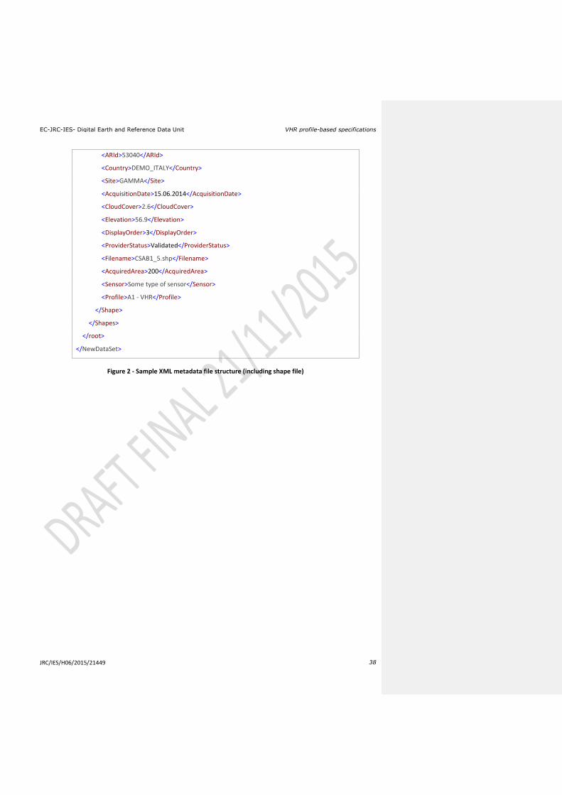
EC-JRC-IES- Digital Earth and Reference Data Unit VHR profile-based specifications
JRC/IES/H06/2015/21449 38
<ARId>53040</ARId>
<Country>DEMO_ITALY</Country>
<Site>GAMMA</Site>
<AcquisitionDate>15.06.2014</AcquisitionDate>
<CloudCover>2.6</CloudCover>
<Elevation>56.9</Elevation>
<DisplayOrder>3</DisplayOrder>
<ProviderStatus>Validated</ProviderStatus>
<Filename>CSAB1_5.shp</Filename>
<AcquiredArea>200</AcquiredArea>
<Sensor>Some type of sensor</Sensor>
<Profile>A1 - VHR</Profile>
</Shape>
</Shapes>
</root>
</NewDataSet>
Figure 2 - Sample XML metadata file structure (including shape file)

EC-JRC-IES- Digital Earth and Reference Data Unit VHR profile-based specifications
JRC/IES/H06/2015/21449 39
17.2. XML metadata file specification for image providers used for the ortho data return to JRC by FW contractor/s
Node name Description Data type Compulsory CWRS_CAMPAIGN Campaign Year Integer yes
ACQUISITION_ID G4CAP Acquisition ID String yes
ZONE_ID Zone name String (maxLength value=5) yes
COUNTRY_ID Country abbreviation (see list) NCName (maxLength
value=2) yes
COPYRIGHT EC_JRC_FC389.911 String (enumeration
value="EC_JRC_FC389.911") yes
PRODUCT_TYPE ORTHO_CWRS String (enumeration
value="ORTHO_CWRS"/> yes
PROCESSING_LEVEL Processing level of imagery
returned String (enumeration
value="3") yes
IMAGE_TYPE Type of the returned image String (enumeration
value="MUL" or "PAN" or "PSH")
yes
LINEAGE Data processed according to
CwRS guidelines. String yes
MISSION
Information about the sensor having provided the source
image from which ortho image has been created.
String (enumeration value="WORLDVIEW" or "
QUICKBIRD" or "IKONOS" or "EROS" or "SKYBOX")
yes
MISSION_INDEX Sensor/mission index String (enumeration
value="1" or " 2" or "3" or "B1")
yes
IMAGING_DATE YYYY-MM-DD Date yes
IMAGING_TIME HH-MM-SS Time yes
DATA_FILE_FORMAT Format of retuned orthos String (enumeration
value="GEOTIFF" or " HFA") yes
DATA_FILE_ORGANISATION Information on the organization
of the files
String (enumeration value=" BAND_COMPOSITE " or " BAND_COMPOSITE ")
yes
Data_File data files of each returned
image file String yes
EPSG EPSG code of returned ortho imagery (coordinate system)
Integer yes
WKT EPSG code description String yes
BAND_INDEX Band index Integer (enumeration
value="1" or "2" or "3" or "4" or "5" or "6" "7" or "8")
yes
BAND_DESCRIPTION Band description Integer (enumeration
value="1" or "2" or "3" or "4" or "5" or "6" "7" or "8")
yes
DATA_TYPE Type of returned data String (enumeration
value="BYTE" or "SHORT" or "LONG ")
yes
NBITS Number of bits per pixel Integer (enumeration
value="8" or "16" or "32") yes
NBANDS Number of returned bands yes
Table 6 - Description of XML metadata file specification for ortho data return to JRC by FW contractor/s
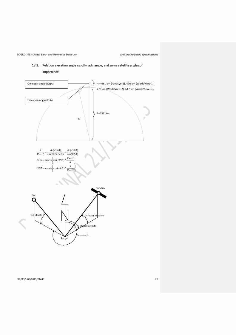
EC-JRC-IES- Digital Earth and Reference Data Unit VHR profile-based specifications
JRC/IES/H06/2015/21449 40
17.3. Relation elevation angle vs. off-nadir angle, and some satellite angles of
importance
HR
RELAONA
R
HRONAELA
ELA
ONA
ELA
ONA
HR
R
*)cos(arcsin
*)sin(arccos
)cos(
)sin(
)º90sin(
)sin(
R
R=6371km
H = 681 km ( GeoEye-1), 496 km (WorldView-1),
770 km (WorldView-2), 617 km (WorldView-3),,
Off-nadir angle (ONA)
Elevation angle (ELA)
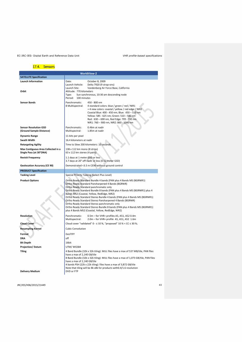
EC-JRC-IES- Digital Earth and Reference Data Unit VHR profile-based specifications
JRC/IES/H06/2015/21449 41
17.4. Sensors
WorldView-2
SATELLITE Specification
Launch Information Date: October 8, 2009 Launch Vehicle: Delta 7920 (9 strap-ons) Launch Site: Vandenberg Air Force Base, California
Orbit Altitude: 770 kilometers Type: Sun synchronous, 10:30 am descending node Period: 100 minutes
Sensor Bands Panchromatic: 450 - 800 nm 8 Multispectral: 4 standard colors: blue / green / red / NIR1 + 4 new colors: coastal / yellow / red edge / NIR2 Coastal Blue: 400 - 450 nm; Blue: 450 – 510 nm Yellow: 585 - 625 nm; Green: 510 – 580 nm Red: 630 – 690 nm, Red Edge: 705 - 745 nm NIR1: 760 – 900 nm, NIR2: 860 - 1040 nm
Sensor Resolution GSD (Ground Sample Distance)
Panchromatic: 0.46m at nadir Multispectral: 1.85m at nadir
Dynamic Range 11-bits per pixel
Swath Width 16.4 kilometers at nadir
Retargeting Agility Time to Slew 200 kilometers: 10 seconds
Max Contiguous Area Collected in a Single Pass (at 30°ONA)
138 x 112 km mono (8 strips) 63 x 112 km stereo (4 pairs)
Revisit Frequency 1.1 days at 1 meter GSD or less 3.7 days at 20° off-nadir or less (0.52 meter GSD)
Geolocation Accuracy (CE 90) Demonstrated <3.5 m CE90 without ground control
PRODUCT Specification
Tasking Level Special Priority Tasking (Select Plus Level)
Product Options Ortho Ready Standard Bundle 4 bands (PAN plus 4 Bands MS (BGRNIR1) Ortho Ready Standard Pansharpened 4 Bands (BGRNIR) Ortho Ready Standard panchromatic only Ortho Ready Standard Bundle 8 bands (PAN plus 4 Bands MS (BGRNIR1) plus 4 Bands MS2 (Coastal, Yellow, RedEdge, NIR2) Ortho Ready Standard Stereo Bundle 4 bands (PAN plus 4 Bands MS (BGRNIR1) Ortho Ready Standard Stereo Pansharpened 4 Bands (BGRNIR) Ortho Ready Standard Stereo panchromatic only Ortho Ready Standard Stereo Bundle 8 bands (PAN plus 4 Bands MS (BGRNIR1) plus 4 Bands MS2 (Coastal, Yellow, RedEdge, NIR2)
Resolution Panchromatic: 0.5m – for VHR+ profiles A5, A51, A52 0.4m Multispectral: 2.0m – for VHR+ profile A5, A51, A52 1.6m
Cloud Cover Cloud cover “validated” 0 - ≤ 10 %, “proposed” 10 % < CC ≤ 30 %;
Resampling Kernel Cubic Convolution
Format GeoTIFF
DRA off
Bit Depth 16bit
Projection/ Datum UTM/ WGS84
Tiling 4 Band Bundle (32k x 32k tiling): MUL files have a max of 537 MB/tile, PAN files have a max of 2,140 GB/tile 8 Band Bundle (32k x 32k tiling): MUL files have a max of 1,073 GB/tile, PAN files have a max of 2,140 GB/tile 4 bands PSH (22k x 22k tiling): files have a max of 3,872 GB/tile Note that tiling will be 8k x8k for products with0.4/1.6 resolution
Delivery Medium DVD or FTP

EC-JRC-IES- Digital Earth and Reference Data Unit VHR profile-based specifications
JRC/IES/H06/2015/21449 42
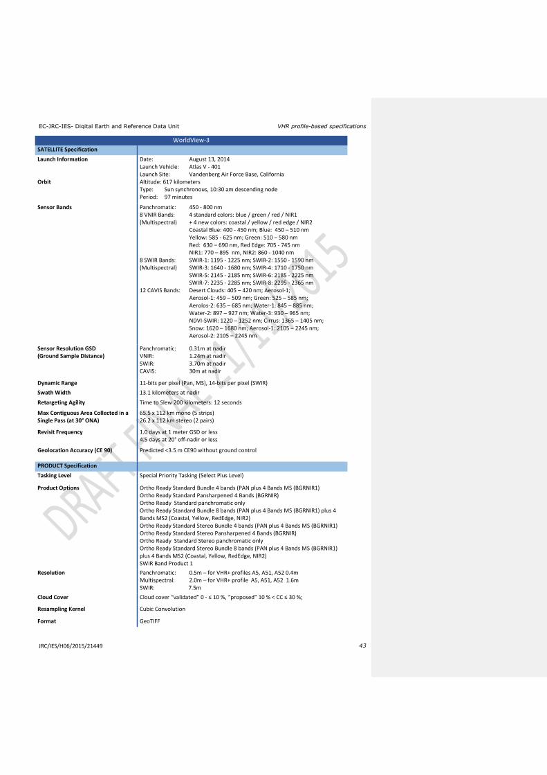
EC-JRC-IES- Digital Earth and Reference Data Unit VHR profile-based specifications
JRC/IES/H06/2015/21449 43
WorldView-3
SATELLITE Specification
Launch Information Date: August 13, 2014 Launch Vehicle: Atlas V - 401 Launch Site: Vandenberg Air Force Base, California
Orbit Altitude: 617 kilometers Type: Sun synchronous, 10:30 am descending node Period: 97 minutes
Sensor Bands Panchromatic: 450 - 800 nm 8 VNIR Bands: 4 standard colors: blue / green / red / NIR1 (Multispectral) + 4 new colors: coastal / yellow / red edge / NIR2 Coastal Blue: 400 - 450 nm; Blue: 450 – 510 nm Yellow: 585 - 625 nm; Green: 510 – 580 nm Red: 630 – 690 nm, Red Edge: 705 - 745 nm NIR1: 770 – 895 nm, NIR2: 860 - 1040 nm 8 SWIR Bands: SWIR-1: 1195 - 1225 nm; SWIR-2: 1550 - 1590 nm (Multispectral) SWIR-3: 1640 - 1680 nm; SWIR-4: 1710 - 1750 nm SWIR-5: 2145 - 2185 nm; SWIR-6: 2185 - 2225 nm SWIR-7: 2235 - 2285 nm; SWIR-8: 2295 - 2365 nm 12 CAVIS Bands: Desert Clouds: 405 – 420 nm; Aerosol-1; Aerosol-1: 459 – 509 nm; Green: 525 – 585 nm; Aerolos-2: 635 – 685 nm; Water-1: 845 – 885 nm; Water-2: 897 – 927 nm; Water-3: 930 – 965 nm; NDVI-SWIR: 1220 – 1252 nm; Cirrus: 1365 – 1405 nm; Snow: 1620 – 1680 nm; Aerosol-1: 2105 – 2245 nm; Aerosol-2: 2105 – 2245 nm
Sensor Resolution GSD (Ground Sample Distance)
Panchromatic: 0.31m at nadir VNIR: 1.24m at nadir SWIR: 3.70m at nadir CAVIS: 30m at nadir
Dynamic Range 11-bits per pixel (Pan, MS), 14-bits per pixel (SWIR)
Swath Width 13.1 kilometers at nadir
Retargeting Agility Time to Slew 200 kilometers: 12 seconds
Max Contiguous Area Collected in a Single Pass (at 30° ONA)
65.5 x 112 km mono (5 strips) 26.2 x 112 km stereo (2 pairs)
Revisit Frequency 1.0 days at 1 meter GSD or less 4.5 days at 20° off-nadir or less
Geolocation Accuracy (CE 90) Predicted <3.5 m CE90 without ground control
PRODUCT Specification
Tasking Level Special Priority Tasking (Select Plus Level)
Product Options Ortho Ready Standard Bundle 4 bands (PAN plus 4 Bands MS (BGRNIR1) Ortho Ready Standard Pansharpened 4 Bands (BGRNIR) Ortho Ready Standard panchromatic only Ortho Ready Standard Bundle 8 bands (PAN plus 4 Bands MS (BGRNIR1) plus 4 Bands MS2 (Coastal, Yellow, RedEdge, NIR2) Ortho Ready Standard Stereo Bundle 4 bands (PAN plus 4 Bands MS (BGRNIR1) Ortho Ready Standard Stereo Pansharpened 4 Bands (BGRNIR) Ortho Ready Standard Stereo panchromatic only Ortho Ready Standard Stereo Bundle 8 bands (PAN plus 4 Bands MS (BGRNIR1) plus 4 Bands MS2 (Coastal, Yellow, RedEdge, NIR2) SWIR Band Product 1
Resolution Panchromatic: 0.5m – for VHR+ profiles A5, A51, A52 0.4m Multispectral: 2.0m – for VHR+ profile A5, A51, A52 1.6m SWIR: 7.5m
Cloud Cover Cloud cover “validated” 0 - ≤ 10 %, “proposed” 10 % < CC ≤ 30 %;
Resampling Kernel Cubic Convolution
Format GeoTIFF

EC-JRC-IES- Digital Earth and Reference Data Unit VHR profile-based specifications
JRC/IES/H06/2015/21449 44
DRA off
Bit Depth 16bit
Projection/ Datum UTM/ WGS84
Tiling 4 Band Bundle (32k x 32k tiling): MUL files have a max of 537 MB/tile, PAN files have a max of 2,140 GB /tile 8 Band Bundle (32k x 32k tiling): MUL files have a max of 1,073 GB/tile, PAN files have a max of 2,140 GB/tile 4 bands PSH (22k x 22k tiling): files have a max of 3,872 GB/tile SWIR Product 1default tiling Note that tiling will be 8k x8k for products with0.4/1.6 resolution
Delivery Medium DVD or FTP
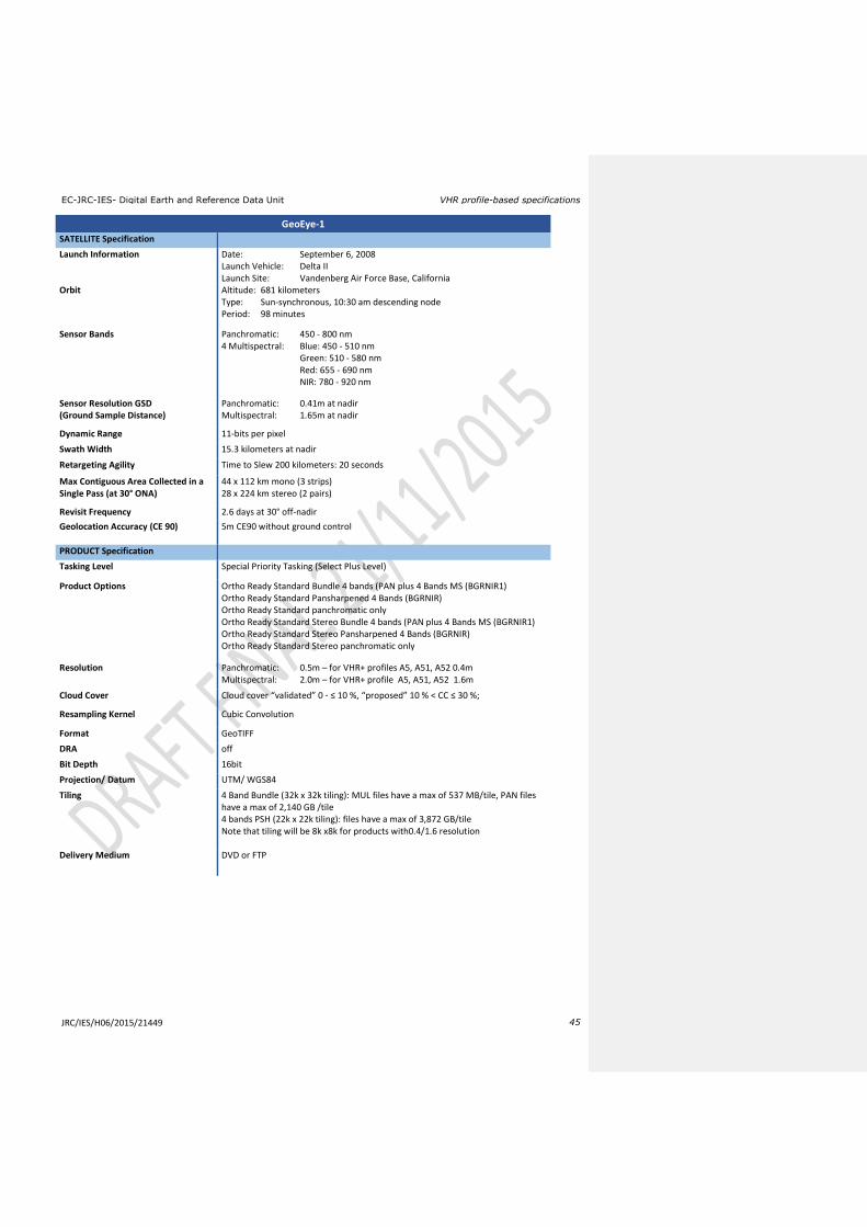
EC-JRC-IES- Digital Earth and Reference Data Unit VHR profile-based specifications
JRC/IES/H06/2015/21449 45
GeoEye-1
SATELLITE Specification
Launch Information Date: September 6, 2008 Launch Vehicle: Delta II Launch Site: Vandenberg Air Force Base, California
Orbit Altitude: 681 kilometers Type: Sun-synchronous, 10:30 am descending node Period: 98 minutes
Sensor Bands Panchromatic: 450 - 800 nm 4 Multispectral: Blue: 450 - 510 nm Green: 510 - 580 nm Red: 655 - 690 nm NIR: 780 - 920 nm
Sensor Resolution GSD (Ground Sample Distance)
Panchromatic: 0.41m at nadir Multispectral: 1.65m at nadir
Dynamic Range 11-bits per pixel
Swath Width 15.3 kilometers at nadir
Retargeting Agility Time to Slew 200 kilometers: 20 seconds
Max Contiguous Area Collected in a Single Pass (at 30° ONA)
44 x 112 km mono (3 strips) 28 x 224 km stereo (2 pairs)
Revisit Frequency 2.6 days at 30° off-nadir
Geolocation Accuracy (CE 90) 5m CE90 without ground control
PRODUCT Specification
Tasking Level Special Priority Tasking (Select Plus Level)
Product Options Ortho Ready Standard Bundle 4 bands (PAN plus 4 Bands MS (BGRNIR1) Ortho Ready Standard Pansharpened 4 Bands (BGRNIR) Ortho Ready Standard panchromatic only Ortho Ready Standard Stereo Bundle 4 bands (PAN plus 4 Bands MS (BGRNIR1) Ortho Ready Standard Stereo Pansharpened 4 Bands (BGRNIR) Ortho Ready Standard Stereo panchromatic only
Resolution Panchromatic: 0.5m – for VHR+ profiles A5, A51, A52 0.4m Multispectral: 2.0m – for VHR+ profile A5, A51, A52 1.6m
Cloud Cover Cloud cover “validated” 0 - ≤ 10 %, “proposed” 10 % < CC ≤ 30 %;
Resampling Kernel Cubic Convolution
Format GeoTIFF
DRA off
Bit Depth 16bit
Projection/ Datum UTM/ WGS84
Tiling 4 Band Bundle (32k x 32k tiling): MUL files have a max of 537 MB/tile, PAN files have a max of 2,140 GB /tile 4 bands PSH (22k x 22k tiling): files have a max of 3,872 GB/tile Note that tiling will be 8k x8k for products with0.4/1.6 resolution
Delivery Medium DVD or FTP
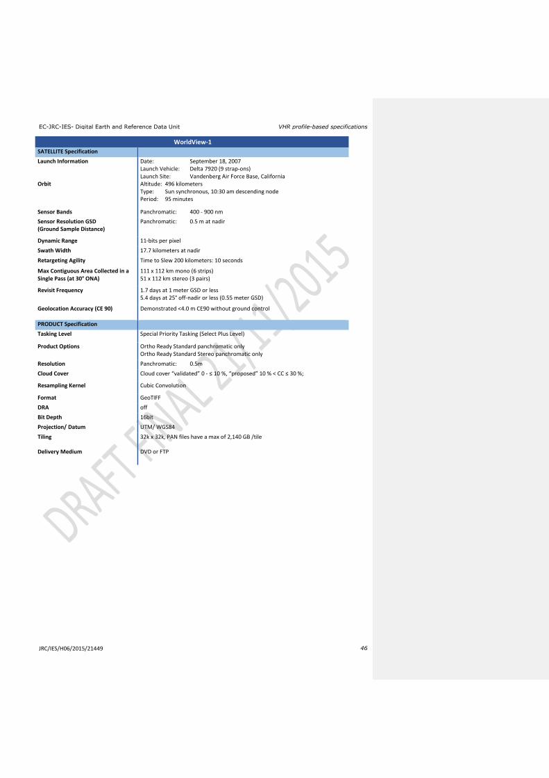
EC-JRC-IES- Digital Earth and Reference Data Unit VHR profile-based specifications
JRC/IES/H06/2015/21449 46
WorldView-1
SATELLITE Specification
Launch Information Date: September 18, 2007 Launch Vehicle: Delta 7920 (9 strap-ons) Launch Site: Vandenberg Air Force Base, California
Orbit Altitude: 496 kilometers Type: Sun synchronous, 10:30 am descending node Period: 95 minutes
Sensor Bands Panchromatic: 400 - 900 nm
Sensor Resolution GSD (Ground Sample Distance)
Panchromatic: 0.5 m at nadir
Dynamic Range 11-bits per pixel
Swath Width 17.7 kilometers at nadir
Retargeting Agility Time to Slew 200 kilometers: 10 seconds
Max Contiguous Area Collected in a Single Pass (at 30° ONA)
111 x 112 km mono (6 strips) 51 x 112 km stereo (3 pairs)
Revisit Frequency 1.7 days at 1 meter GSD or less 5.4 days at 25° off-nadir or less (0.55 meter GSD)
Geolocation Accuracy (CE 90) Demonstrated <4.0 m CE90 without ground control
PRODUCT Specification
Tasking Level Special Priority Tasking (Select Plus Level)
Product Options Ortho Ready Standard panchromatic only Ortho Ready Standard Stereo panchromatic only
Resolution Panchromatic: 0.5m
Cloud Cover Cloud cover “validated” 0 - ≤ 10 %, “proposed” 10 % < CC ≤ 30 %;
Resampling Kernel Cubic Convolution
Format GeoTIFF
DRA off
Bit Depth 16bit
Projection/ Datum UTM/ WGS84
Tiling 32k x 32k, PAN files have a max of 2,140 GB /tile
Delivery Medium DVD or FTP
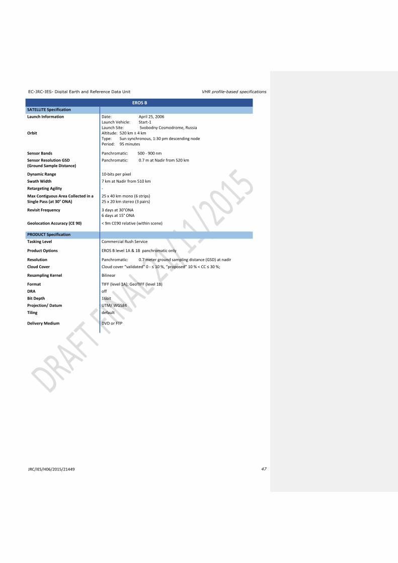
EC-JRC-IES- Digital Earth and Reference Data Unit VHR profile-based specifications
JRC/IES/H06/2015/21449 47
EROS B
SATELLITE Specification
Launch Information Date: April 25, 2006 Launch Vehicle: Start-1 Launch Site: Svobodny Cosmodrome, Russia
Orbit Altitude: 520 km ± 4 km Type: Sun synchronous, 1:30 pm descending node Period: 95 minutes
Sensor Bands Panchromatic: 500 - 900 nm
Sensor Resolution GSD (Ground Sample Distance)
Panchromatic: 0.7 m at Nadir from 520 km
Dynamic Range 10-bits per pixel
Swath Width 7 km at Nadir from 510 km
Retargeting Agility -
Max Contiguous Area Collected in a Single Pass (at 30° ONA)
25 x 40 km mono (6 strips) 25 x 20 km stereo (3 pairs)
Revisit Frequency 3 days at 30°ONA 6 days at 15° ONA
Geolocation Accuracy (CE 90) < 9m CE90 relative (within scene)
PRODUCT Specification
Tasking Level Commercial Rush Service
Product Options EROS B level 1A & 1B panchromatic only
Resolution Panchromatic: 0.7 meter ground sampling distance (GSD) at nadir
Cloud Cover Cloud cover “validated” 0 - ≤ 10 %, “proposed” 10 % < CC ≤ 30 %;
Resampling Kernel Bilinear
Format TIFF (level 1A); GeoTIFF (level 1B)
DRA off
Bit Depth 16bit
Projection/ Datum UTM/ WGS84
Tiling default
Delivery Medium DVD or FTP
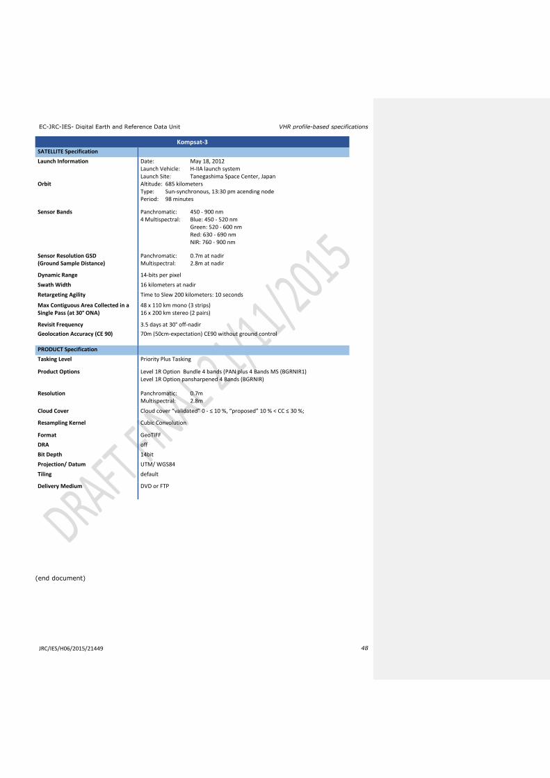
EC-JRC-IES- Digital Earth and Reference Data Unit VHR profile-based specifications
JRC/IES/H06/2015/21449 48
(end document)
Kompsat-3
SATELLITE Specification
Launch Information Date: May 18, 2012 Launch Vehicle: H-IIA launch system Launch Site: Tanegashima Space Center, Japan
Orbit Altitude: 685 kilometers Type: Sun-synchronous, 13:30 pm acending node Period: 98 minutes
Sensor Bands Panchromatic: 450 - 900 nm 4 Multispectral: Blue: 450 - 520 nm Green: 520 - 600 nm Red: 630 - 690 nm NIR: 760 - 900 nm
Sensor Resolution GSD (Ground Sample Distance)
Panchromatic: 0.7m at nadir Multispectral: 2.8m at nadir
Dynamic Range 14-bits per pixel
Swath Width 16 kilometers at nadir
Retargeting Agility Time to Slew 200 kilometers: 10 seconds
Max Contiguous Area Collected in a Single Pass (at 30° ONA)
48 x 110 km mono (3 strips) 16 x 200 km stereo (2 pairs)
Revisit Frequency 3.5 days at 30° off-nadir
Geolocation Accuracy (CE 90) 70m (50cm-expectation) CE90 without ground control
PRODUCT Specification
Tasking Level Priority Plus Tasking
Product Options Level 1R Option Bundle 4 bands (PAN plus 4 Bands MS (BGRNIR1) Level 1R Option pansharpened 4 Bands (BGRNIR)
Resolution Panchromatic: 0.7m Multispectral: 2.8m
Cloud Cover Cloud cover “validated” 0 - ≤ 10 %, “proposed” 10 % < CC ≤ 30 %;
Resampling Kernel Cubic Convolution
Format GeoTIFF
DRA off
Bit Depth 14bit
Projection/ Datum UTM/ WGS84
Tiling default
Delivery Medium DVD or FTP