canvas 5.0 : c:documents and settingsslandgrenmy ... 511-94101 to 511-xxxxx... · machine...
TRANSCRIPT


MACHINE SPECIFICATIONS
MODEL SERIAL NO.
PHASECYCLEVOLTAGE
For your information and future reference, insert pertinent data concerning your ma-chine in the spaces provided above. This information is printed on a label or stamped ona plate attached to the machine frame.
Always specify model and serial numbers on all parts orders and correspondence concerning your machine. This will help avoid unnecessary delays and inconvenience during processing.
The specifications contained herein were in effect at the time this manual was approved for printing. The DoALL Company, whose policy is one of continuous product improve-ment, reserves the right to change specifications or design at any time without notice and without incurring obligations.
How to read your serial number:
CHECK OUR WEB SITE FOR YOUR NEAREST SERVICE REPRESENTATIVE.
For Sales, Parts and Service, call 1-888-362-5572For general information, visit our web site at: www.doallsawing.com
DoALL SAWING PRODUCTS2375B TOUHY AVENUEELK GROVE, ILLINOIS 60007 U.S.A.

MANUAL INDEX 6/08
Fiche No. Model C-650M Serial No. 509-94101 to PAGE NO. DESCRIPTION FIRST SERIAL LAST SERIAL PAGES PS-1-111 Final Assembly All 2 - 3 PS-2-102 Band Anti-Sqeal Assembly 509-94101 to 510-95102 4 - 5 PS-2-102 Band Brush Assembly All 4 - 5 PS-2-103 Band Tension Slide Assembly All 6 - 7 PS-10-65 *Band Twist Indicator Assembly All 8 - 9 PS-1-110 Base Assembly ALL 10 - 11 PS-9-203 Chip Conveyor Assembly 5109-94101 to 509-95102 12 - 13 PS-9-165 Chip Conveyor Assembly 509-96103 to 14 - 15 PS-8-200 Control Box Assembly (Variable Speed) All 16 - 17 PS-7-204 Control Console Assembly 509-94101 to 509-95102 18 - 19 PS-7-366 Control Console Assembly 509-06103 to 20 - 21 PS-8-322 Control Panel Assembly (Relay) 509-94101 to 509-95102 22 - 23 PS-8-336 Control Panel Assembly (Relay) 509-06103 to 24 - 25 PS-10-67 *Conveyor Assemblies All 26 - 27 PS-6-44 Coolant Assembly All 28 - 29 PS-3-127 *Discharge Tray Assembly All 30 - 31 PS-4-107 Drive Assembly All 32 - 33 PS-8-211 Electrical Assembly 509-94101 to 509-95102 34 - 35 PS-8-337 Electrical Assembly 509-06103 to 36 - 37 PS-7-272 Feed Rate Valve Detail All 42 - 43 PS-6-44 Flushing Hose All 28 - 29 PS-2-114 Head Assembly All 38 - 39 PS-1-111 Head Lift Cylinder Detail All 2 - 3 PS-7-271 Head Lift Cylinder Hydraulics All 40 - 41 PS-7-273 Head Manifold Assembly All 44 - 45 PS-7-271 Hydraulic Assembly (Rear View - L.H. Side) All 40 - 41 PS-7-272 Hydraulic Assembly (Rear View - R.H. Side) All 42 - 43 PS-7-273 Hydraulic Assembly (Head Manifold Assembly) 509-94101 to 509-95102 44 - 45 PS-7-367 Hydraulic Assembly (Head Manifold Assembly) 509-96101 to 46 - 47 PS-7-274 Hydraulic Assembly (Vises) All 48 - 49 PS-7-275 Hydraulic Assembly (Power Unit) 509-94101 to 509-95102 50 - 61 PS-7-368 Hydraulic Assembly (Power Unit) 509-06103 to 52 - 53 PS-7-276 Hydraulic Assembly (Variable Vise Pressure) All 54 - 55 PS-9-168 *Hydraulic Assembly (Vertical Hold Down Option) All 56 - 57 PS-7-373 Hydraulic Control Panel Assembly All 58 - 59 PS-2-114 Idler Bandwheel Detail All 38 - 39 PS-1-110 Inboard Vise Detail All 10 - 11 PS-10-87 *Laser Line Generator Assembly All 60 - 61 PS-7-272 *Metered Feed Option All 42 - 43 PS-6-58 *Mist Lubricator Assembly All 62 - 63 PS-9-204 *Outboard Vise Assembly All 64 - 65 PS-8-321 Pushbutton Panel Assembly All 66 - 67 PS-5-63 Saw Guide Assembly (Left Hand) 509-94101 to 509-95102 68 - 69 PS-5-70 Saw Guide Assembly (Left Hand) 509-06103 to 70 - 71 PS-5-64 Saw Guide Assembly (Right Hand) All 72 - 73 PS-7-272 Servo Feed Valve (Standard) All 42 - 43 PS-4-100 Transmission Assembly All 74 - 75 PS-7-276 Variable Vise Pressure Detail All 54 - 55 PS-9-171 *Vertical Hold Down Assembly All 76 - 77 *Denotes Attachment or Optional Equipment.
1

PS - 1 - 111 PRINTED IN U.S.A.
MODEL FIRST MACH. LAST MACH.C-650M 509-94101
FINAL ASSEMBLY
1236789
10
1213
14
1516
45
11
17 18 19 20 21 22 23 2425
2627
2829
3031
3233
34
35
36373839404142434445
NEW DRG.S.C.L. 4-8-98
REVISIONSS.C.L. 3-28-05S.C.L. 7-11-06
2

CODE NO. PS-1-111 ____________ ____________
FINAL ASSEMBLY INDEX PART DESCRIPTION UNITS PER NO. NO. ASS'Y. Ref. 290173 Final Assembly 1 319841 . Access Cover .................................................................................................................... 1 2 199969 . Screw, Button Hd. Soc. M6 x 1.0 x 10 .............................................................................. 2 3 206311 . Base Assembly (See Detail) ............................................................................................. 1 4 418015 . Splash Guard .................................................................................................................... 1 5 199819 . Screw, Soc. Hd. Cap M8 x 1.25 x 16 ................................................................................ 2 6 516749 . Polypac/Electrics Support Weldment ................................................................................ 1 417856 . Polypac Mounting Plate .................................................................................................... 1 7 199818 . Screw, Soc. Hd. Cap M10 x 1.5 x 20 ................................................................................ 8 8 417551 . Top Cover .......................................................................................................................... 1 9 199991 . Screw, Soc. Hd. Locking M6 x 1.0 x 12 ............................................................................ 9 10 417553 . Front Cover ....................................................................................................................... 1 11 199991 . Screw, Soc. Hd. Locking M6 x 1.0 x 12 ............................................................................ 8 12 417554 . Door Weldment ................................................................................................................. 1 13 199991 . Screw, Soc. Hd. Locking M6 x 1.0 x 12 ............................................................................ 5 14 172762 . Door Latch ......................................................................................................................... 1 15 417552 . Top Louvred Cover ........................................................................................................... 1 16 199991 . Screw, Soc. Hd. Locking M6 x 1.0 x 12 ............................................................................ 10 17 320006 . Tube Cover ........................................................................................................................ 2 18 199969 . Screw, Button Hd. Soc. M6 x 1.0 x 10 .............................................................................. 4 19 055734 . Name Plate (DoALL) ......................................................................................................... 2 20 204450 . Slotted Nut M120 x 2.0 (Self-Locking) .............................................................................. 2 21 516661 . Transverse Weldment ....................................................................................................... 1 22 205627 . Label (Feed Force) ............................................................................................................ 1 23 201465 . Label (Warning - Saw Blade) ............................................................................................ 1 24 206626 . Head Assembly (See Detail) ............................................................................................. 1 25* 223030 . Head Lift Cylinder ............................................................................................................. 1 26 204171 . Cylinder Mount .................................................................................................................. 2 27 199962 . Screw, Soc. Hd. Cap M16 x 2.0 x 110 .............................................................................. 4 28 319490 . Clevis Mount ...................................................................................................................... 2 29 199962 . Screw, Soc. Hd. Cap M16 x 2.0 x 110 .............................................................................. 8 30 204408 . Rod Eye ............................................................................................................................. 1 31 199961 . Screw, Soc. Set M6 x 1.0 x 12 (Cone Pt.) ........................................................................ 1 32 204407 . Pin ..................................................................................................................................... 1 33 35-007558 . Retaining Ring ................................................................................................................... 2 34 201469 . Decal (Flag) ....................................................................................................................... 1 35 518276 . Chip Conveyor Assembly (Optional) (See Detail) ............................................................. 1 36 208578 . Coolant Assembly (See Detail) ......................................................................................... 1 37 200179 . Escutcheon (Warning - Rake Chips) ................................................................................. 1 38 205767 . Saw Band (2" Silencer) ..................................................................................................... 1 39 201465 . Label (Warning - Saw Blade) ............................................................................................ 1 40 201466 . Label (Warning - Vise) ...................................................................................................... 2 41 417664 . Job Selector ...................................................................................................................... 1 42 404478 . Escutcheon (Warning) ....................................................................................................... 1 43 201467 . Label (Warning - Eye Protection) ...................................................................................... 1 44 209652 . Label (Diameters/X-Sections Area) .................................................................................. 1 45 206323 . Electrical Assembly (See Detail) ....................................................................................... 1 *NOTE: Item #25 Was #418710 Before Serial #509-06103. Following Not Shown: 417811 . R.H. Front Splash Guard Assembly .................................................................................. 1 206271 . Rear Splash Guard ........................................................................................................... 1 199990 . Screw, Soc. Hd. Locking M5 x 0.8 x 12 ............................................................................ 4 421334 . Rear Cover (Power Unit Enclosure) .................................................................................. 1 323891 . Escutcheon (Machine Specifications) ............................................................................... 1 201468 . Label (Warning - Clear Vise) ............................................................................................. 4 207159 . Tag (Connect Cylinder Rod Before Hyd. Lines) ............................................................... 1 223034 . Manual on CD ................................................................................................................... 1 214770 . DoALL Cutting Fluid .......................................................................................................... 1 206328 . Extra Parts ......................................................................................................................... 1 409529 . . Shovel/Rake .................................................................................................................... 1 012420 . . Foot Casting .................................................................................................................... 4 199931 . . Screw, Soc. Hd. Cap M16 x 2.0 x 60 .............................................................................. 4 199955 . . Nut, Hex. Jam M16 x 2.0 ................................................................................................. 4
3

������������ ���� ��������
�� ����������������������������
������ ���������
������ ���������
������ ���������
�� ���������������
�� �������������������
���
�
�
�
�
�
��������
�� ����������������������������
������ ��������� ���������
������ ��������� ���������
�� ����������������������������
������ ��������� ���������
�
��
�
�
�
�
�
�
�
�
�
�!� �"�
��������������
��#���
��������������
������� �����
4

CODE NO. PS-2-102 ____________ ____________
BAND ANTI-SQUEAL ASSEMBLY
BAND BRUSH ASSEMBLY INDEX PART DESCRIPTION UNITS PER NO. NO. ASS'Y. Ref. 417702 Band Anti-Squeal Assembly (From Serial #510-94101 thru #510-94108) 1 320217 . Mounting Bar .......................................................................................... 1 2 199138 . Nut, Hex. Jam 5/8-18NF ........................................................................ 1 3 199267 . Washer, Flat 5/8 S.A.E. Std. .................................................................. 1 4 202383 . Loctite Adhesive (242-31 Threadlock) ................................................... A.R. 5 320218 . Mounting Bar .......................................................................................... 1 6 198558 . Screw, Soc. Set M4-0.7 x 8 (Cone Point) .............................................. 1 7 199744 . Screw, Soc. Hd. Cap M8-1.25 x 55 ....................................................... 2 8 320219 . Anti-Squeal Roller Assembly ................................................................. 1 205770 . . Bearing ................................................................................................. 1 205784 . . Roller .................................................................................................... 1 205771 . . Tire (Use Loctite #410) ........................................................................ 1 205769 . . Eccentric Bushing (Use Loctite #635) .................................................. 1 199123 . . Nut, Hex. Jam 5/16-18NC .................................................................... 1 Ref. 417702 Band Anti-Squeal Assembly (Serial #510-94109 and all C-650M) 1 206348 . Bracket ................................................................................................... 1 2 199138 . Nut, Hex. Jam 5/8-18NF ........................................................................ 1 3 199267 . Washer, Flat 5/8 S.A.E. Std. .................................................................. 1 4 207123 . Spacer .................................................................................................... 1 5 320219 . Anti-Squeal Roller Assembly ................................................................ 1 205770 . . Bearing ................................................................................................. 1 205784 . . Roller .................................................................................................... 1 205771 . . Tire (Use Loctite #410) ........................................................................ 1 205769 . . Eccentric Bushing (Use Loctite #410) .................................................. 1 198123 . . Nut, Hex. Jam 5/16-18NC .................................................................... 1 Ref.* 205892 Band Brush Assembly 1 199719 . Screw, Soc. Hd. Cap M8-1.25 x 40 (Part of Head Assembly) ............... 2 2 204412 . Pivot Clamp (Part of Head Assembly) ................................................... 1 3 199969 . Screw, Button Hd. Soc. M6-1.0 x 10 ...................................................... 3 4 204468 . Wire Brush ............................................................................................. 1 5 198423 . Screw, Soc. Set 1/4-20NC x 5/16 .......................................................... 1 6 199217 . Nut, Hex. Jam 3/8-16NC (L.H. Thread) ................................................. 1 7 199325 . Washer, Lock 3/8 Std. ............................................................................ 1 8 199264 . Washer, Flat 3/8 S.A.E. Std. .................................................................. 1 9 417342 . Cover ...................................................................................................... 1 10 516666 . Mount Weldment .................................................................................... 1 11 199771 . Screw, Button Hd. Soc. 1/4-20NC x 1/2 ................................................ 3 12 319944 . Adaptor ................................................................................................... 1 13 175353 . Hydraulic Motor ...................................................................................... 1 *NOTE: Before Serial #510-94109 Band Brush Assembly was 204433.
5
NEW DRG.S.C.L. 3-24-98
REVISIONS
PS - 2 - 103 PRINTED IN U.S.A.
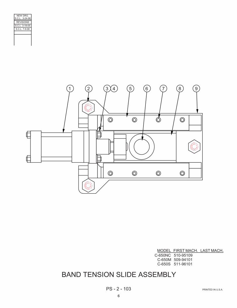
MODEL FIRST MACH. LAST MACH.C-650NC 510-95109
C-650M 509-94101C-650S 511-96101
BAND TENSION SLIDE ASSEMBLY
1 2 3 4 5 6 7 8 9
S.C.L. 3-18-05S.C.L. 7-9-08
6

CODE NO. PS-2-103 ____________ ____________
BAND TENSION SLIDE ASSEMBLY
INDEX PART DESCRIPTION UNITS PER NO. NO. ASS'Y. Ref. 205890 Band Tension Slide Assembly 1 417703 . Band Tension Cylinder ........................................................................... 1 2 320301 . Push-Pull Screw M36-3.0-6G ................................................................ 3 3 199197 . Nut, Hex M16-1.5 ................................................................................... 4 4 199285 . Washer, Flat M16 ................................................................................... 4 5 417708 . Retainer Bar ........................................................................................... 2 6 517101 . Idler Wheel Shaft ................................................................................... 1 7 199918 . Screw, Soc. Hd. Cap M12-1.75 x 45 ..................................................... 8 8 417707 . Slide Weldment ...................................................................................... 1 9 516832 . Slide Housing Weldment ........................................................................ 1
7

NEW DRG.S.C.L. 1-15-98
REVISIONS
PS - 10 - 65 TF - 5 - 51 PRINTED IN U.S.A.
BAND TWIST INDICATOR OPTION
- -+ +
SEE DETAILABOVELEFT
ADJUSTING SCREW ASSEMBLY
1 2 3 4 5 6
1
23
45
67 8
9
1011
12
1314
ENCLOSURE ASSEMBLY
COVER REMOVED
1
2
3
4
5
6
7
8 9 10
11
12
13
1415
16
1718 19
20
24
2526
27
2123
22
S.C.L. 1-25-05S.C.L. 11-8-06S.C.L. 5-19-08
8

CODE NO. PS-10-65 TF-5-51 __________
BAND TWIST INDICATOR ASSEMBLY INDEX PART DESCRIPTION UNITS PER NO. NO. ASS'Y. Ref. 203116 Band Twist Indicator Option (C-305) Ref. 203122 Band Twist Indicator Option (C-4100) (TF-2525) Ref. 205854 Band Twist Indicator Option (C-3300) Ref. 205075 Band Twist Indicator Option (C-650, C-820) Ref. 516282 . Band Twist Indicator Head Assembly 1 197345 . . Shielded Cable (#20-3 Conductor) ... A.R. 2 178139 . . Cord Grip ........................................... 1 3 516280 . . Body .................................................. 1 4 198242 . . Screw, Soc. Hd. Cap 1/4-20NC x 1 ... 2 5 417169 . . Extension Arm ................................... 1 6 198241 . . Screw, Soc. Hd. Cap 1/4-20NC x 7/8 2 7 124419 . . Adjusting Screw Assembly (See Detail) 1 8 320553 . Insert Assembly (Adjustable) (C-305, C-3300) ................................................ 1 319092 . Insert Assembly (Adjustable) (C-4100, C-650, C-820, TF-2525) ...................... 1 9 320734 . Insert Assembly (Fixed) (C-305, C-3300) 1 319093 . Insert Assembly (Fixed) (C-4100, C-650, C-820, TF-2525) .................................. 1 10 198219 . Screw, Soc. Hd. Cap #10-24NC x 3/8 . 1 11 417168 . . Clevis ................................................. 1 12 203167 . . Clamp Plate ....................................... 1 13 319401 . . Spring Plate ....................................... 1 14 319399 . . Cover ................................................. 1 15 319403 . . Gasket ............................................... 1 16 198398 . . Screw, Button Hd. Soc. #8-32NC x 1/4 4 17 198225 . . Screw, Soc. Hd. Cap #10-24NC x 1 (Mounting) ......................................... 2 18 199319 . . Washer, Lock #10 Std. (Mounting) .... 2 19 178655 . . Terminal Block ................................... 1 20 136893 . . Meta Grip Glue (#3802) ..................... A.R. 21 198199 . Wire, #22 Black (Vinyl) ........................ A.R. 22 198278 . Wire, #22 Red (Vinyl) .......................... A.R. 23 197286 . Wire, #22 White (Vinyl) ........................ A.R. 24 197435 . . Neoprene Sponge ............................. 1 25 178651 . . Proximity Sensor ............................... 1 26 136893 . . Meta Grip Glue (#3802) ..................... A.R. 27 203169 . . Silicon Sealant ................................... 1 Following Not Shown: 14-000661 . Close Nipple (C-305) ........................... 2 005258 . Pipe Nipple (C-4100, C-3300, C-650, C-820, TF-2525) .............................................. 2 014411 . Flange Washer .................................... 4 019543 . Bond Nut .............................................. 4 203364 . Spacer (.88) (C-4100, C-3300, C-650, C-820, TF-2525) .................................. 2 203871 . Spacer (.13) (C-4100, C-3300, C-650, C-820) .................................................. 2 199269 . Washer, Flat 7/8 S.A.E. Std. (C-305) .. 2 011803 . Plastic Cap/Plug (Remount Scale – C-3300) ................................................ 2 199730 . Screw, Phillips Hd. Self-Tap #4-40NC x 1/2 (Remount Scale - C-3300) .......... 3 199721 . . Screw, Rd. Hd. Mach. #6-32NC x 1/2 (Nylon) .............................................. 2
INDEX PART DESCRIPTION UNITS PERNO. NO. ASS'Y. Ref. 124419 . . Adjusting Screw Assembly 1 124417 . . . Plunger ............................................. 1 2 199257 . . . Washer, Flat #8 S.A.E. Std. ............. 1 3 124418 . . . Housing ............................................ 1 4 104632 . . . Belleville Washer ............................. 6 5 004217 . . . Roll Pin ............................................ 1 6 124033 . . . Plug .................................................. 1 Ref. 417170 . Enclosure Assembly 1 417171 . . Enclosure ........................................... 1 2 178856 . . L.E.D. Display Board .......................... 1 3 178148 . . Bezel .................................................. 1 4 416197 . . P.C. Board ......................................... 1 5 317901 . . Flat Cable Assembly .......................... 1 6 207188 . . Pushbutton Operator (Black) ............. 1 7 207185 . . Contact Block (1-NO) ......................... 1 8 207181 . . Selector Switch (2 Position) ............... 1 9 207185 . . Contact Block (1-NO) ......................... 1 10 178714 . . Potentiometer ..................................... 1 11 178146 . . Knob ................................................... 1 12 317720 . . Escutcheon ........................................ 1 13 178714 . . Potentiometer ..................................... 1 14 178146 . . Knob ................................................... 1
9

PS - 1 - 110 PRINTED IN U.S.A.
MODEL FIRST MACH. LAST MACH.C-650M 509-94101
BASE ASSEMBLY
12
346781012139
1411
155
1618
1719202122
23
24 25 26 27 28 29 3031
3233
3435
36 38
41424344454647484950
51
5253
5455
56 5758
59
60
MOVABLE VISE JAW
3940
37
NEW DRG.S.C.L. 4-8-98
REVISIONSS.C.L. 3-20-05S.C.L. 7-11-06
10

CODE NO. PS-1-110 ____________ ____________
BASE ASSEMBLY INDEX PART DESCRIPTION UNITS PER NO. NO. ASS'Y. Ref. 206311 Base Assembly 1 517188 . R.H. Material Guide Weldment .................................................................................................. 1 2 206332 . Standoff ..................................................................................................................................... 4 3 199901 . Screw, Soc. Hd. Cap M12 x 1.75 x 110 ..................................................................................... 4 4 516658 . Wear Plate ................................................................................................................................. 2 5 199904 . Screw, Soc. Hd. Cap M12 x 1.75 x 40 ....................................................................................... 12 6 204466 . Key ............................................................................................................................................ 4 7 204417 . Spacer (Under Wear Plates) ..................................................................................................... 4 8 199902 . Screw, Soc. Hd. Cap M12 x 1.75 x 85 ....................................................................................... 4 9 417347 . Roller ......................................................................................................................................... 4 10 204428 . Bearing ...................................................................................................................................... 8 11 204455 . Retaining Ring ........................................................................................................................... 8 12 204464 . Spacer ....................................................................................................................................... 12 13 417343 . Outboard Wear Plate ................................................................................................................. 1 14 417341 . Inboard Wear Plate .................................................................................................................... 1 15 417215 . Roller Shaft ................................................................................................................................ 4 16 199900 . Screw, Soc. Hd. Cap M12 x 1.75 x 30 ....................................................................................... 8 17 517187 . L.H. Material Guide Weldment .................................................................................................. 1 18 206332 . Standoff ..................................................................................................................................... 4 19 199901 . Screw, Soc. Hd. Cap M12 x 1.75 x 110 ..................................................................................... 4 20 517186 . Base Weldment ......................................................................................................................... 1 21 516659 . Column ...................................................................................................................................... 2 22 199948 . Screw, Soc. Hd. Cap M12 x 1.75 x 65 (Base) ........................................................................... 6 23 204472 . Spher Washer (2 Piece) (Base) ................................................................................................. 6 24 417509 . Inboard L.H. Clamp Cylinder ..................................................................................................... 1 25 199948 . Screw, Soc. Hd. Cap M12 x 1.75 x 65 ....................................................................................... 4 26 319805 . L.H. Cylinder Extension ............................................................................................................. 1 27 516613 . L.H. Movable Jaw ...................................................................................................................... 1 28 417545 . Strike Bar ................................................................................................................................... 1 29 199903 . Screw, Soc. Hd. Cap M8 x 1.25 x 20 ......................................................................................... 2 30 516827 . Wear Plate (2 Each Jaw) ........................................................................................................... 4 31 199946 . Screw, Soc, Hd. Cap M8 x 1.25 x 20 (Low Head) ..................................................................... 12 32 204493 . Shim (.002) ................................................................................................................................ A.R. 33 204494 . Shim (.003) ................................................................................................................................ A.R. 34 204495 . Shim (.008) ................................................................................................................................ A.R. 35 204496 . Shim (.025) ................................................................................................................................ A.R. 36 516612 . R.H. Fixed Jaw .......................................................................................................................... 1 37 204467 . Key ............................................................................................................................................ 1 38 199931 . Screw, Soc. Hd. Cap M16 x 2.0 x 60 ......................................................................................... 4 39 207156 . Cover ......................................................................................................................................... 1 40 199929 . Screw, Soc. Hd. Cap M12 x 1.75 x 20 ....................................................................................... 4 41 108601 . Plug Button ................................................................................................................................ 1 42 204400 . Jaw Wiper .................................................................................................................................. 1 43 199974 . Screw, Button Hd. Soc. M5 x 0.8 x 10 ..................................................................................... 2 44 204462 . Alignment Coupler ..................................................................................................................... 1 45 207151 . Jaw Wiper .................................................................................................................................. 1 46 199974 . Screw, Button Hd. Soc. M5 x 0.8 x 10 ....................................................................................... 3 47 417431 . Spacer ....................................................................................................................................... 2 48 199918 . Screw, Soc. Hd. Cap M12 x 1.75 x 45 ....................................................................................... 16 49 199994 . Screw, Soc. Set M10 x 1.5 x 25 (Dog Pt.) ................................................................................. 12 50 417344 . Retaining Flange (2 Piece) ........................................................................................................ 2 51 319812 . Way Plate .................................................................................................................................. 2 52 204488 . Shim (.002) ................................................................................................................................ A.R. 53 204489 . Shim (.003 ................................................................................................................................. A.R. 54 204490 . Shim (.008) ................................................................................................................................ A.R. 55 204497 . Shim (.025) ................................................................................................................................ A.R. 56 199742 . Screw, Soc. Hd. Cap M12 x 1.75 x 35 ....................................................................................... 6 57 199944 . Screw, Soc. Set M10 x 1.5 x 45 ................................................................................................. 4 58 199976 . Nut, Hex. Jam M10 x 1.5 ........................................................................................................... 4 59 319485 . Vise Gib ..................................................................................................................................... 1 60 199947 . Screw, Soc. Hd. Cap 1-14NF x 2.5 ............................................................................................ 1
11

NEW DRG.S.C.L. 11-1-94
REVISIONS
PS - 9 - 203 PRINTED IN U.S.A.
MODEL FIRST MACH. LAST MACH.C-650NC 510-94108 510-98120
C-650M 509-06101 509-95102
CHIP CONVEYOR ASSEMBLY
1
3
45
67
8910 11 12 13 14
1516
1718
2324
25
2627
2829
3031
32 33 36 37 3839
4041
1920
2122
S.C.L. 8-29-96
2
34 35
12

CODE NO. PS-9-203 ____________ ____________
CHIP CONVEYOR ASSEMBLY
INDEX PART DESCRIPTION UNITS PER NO. NO. ASS'Y. Ref. 417819 Chip Conveyor Assembly 1 205172 . Sprocket ................................................................................................. 1 2 101580 . Key ......................................................................................................... 1 3 205175 . Standoff .................................................................................................. 1 4 175353 . Chip Conveyor Motor ............................................................................. 1 5 198099 . Screw, Hex. Hd. Cap 1/4-28NF x 3/4 ................................................... 3 6 199321 . Washer, Lock 1/4 Std. ............................................................................ 3 7 199260 . Washer, Flat 1/4 S.A.E. Std. .................................................................. 3 8 199926 . Screw, Soc. Hd. Cap M8-1.25 x 25 ....................................................... 3 9 199968 . Washer, Lock M8 ................................................................................... 3 10 199967 . Washer, Flat M8 ..................................................................................... 3 11 319976 . Mounting Plate ....................................................................................... 1 12 205174 . Roller Chain ........................................................................................... 1 13 206283 . Sprocket ................................................................................................. 1 14 101580 . Key ......................................................................................................... 1 15 206285 . Flange Bearing ....................................................................................... 1 16 199896 . Screw, Soc. Hd. Cap M10-1.5 x 25 ....................................................... 2 17 199346 . Washer, Lock M10 ................................................................................. 2 18 198976 . Washer, Flat M10 ................................................................................... 2 19 320649 . Tension Slide Weldment ........................................................................ 1 20 199680 . Screw, Soc. Hd. Cap M10-1.5 x 30 ....................................................... 3 21 199346 . Washer, Lock M10 ................................................................................. 3 22 198976 . Washer, Flat M10 ................................................................................... 6 23 206284 . Sprocket ................................................................................................. 1 24 004287 . Spring Pin ............................................................................................... 1 25 320355 . Shaft ....................................................................................................... 1 26 206284 . Sprocket ................................................................................................. 1 27 004287 . Spring Pin ............................................................................................... 1 28 206285 . Flanged Bearing ..................................................................................... 1 29 199896 . Screw, Soc. Hd. Cap M10-1.5 x 25 ....................................................... 2 30 199346 . Washer, Lock M10 ................................................................................. 2 31 198976 . Washer, Flat M10 ................................................................................... 2 32 206286 . Apron Belt .............................................................................................. 1 33 518274 . Chip Conveyor Weldment ...................................................................... 1 34 206824 . Bottom Drive Cover ................................................................................ 1 35 199969 . Screw, Button Hd. Soc. M6-1.0 x 10 ...................................................... 2 36 320354 . Drive Guard ............................................................................................ 1 37 199969 . Screw, Button Hd. Soc. M6-1.0 x 10 ...................................................... 4 38 320755 . Mounting Plate ....................................................................................... 1 39 199680 . Screw, Soc. Hd. Cap M10-1.5 x 30 ....................................................... 4 40 199346 . Washer, Lock M10 ................................................................................. 4 41 198976 . Washer, Flat M10 ................................................................................... 8
13

��������
������ �� ��
�������
�� ��� ���� ����������������
����������������������������
���� ��� �����
���� ��� �����
��� ��� �����
���� ��� �����
��������������� ���� ��� �����
�������� ������!�
�
�
�
�
�
�
"
�
� �� �� �� ��
����
���"
��
��
��
��
��
�"����
��
�� �� �� �� ��
��
�"
��
����
����
������ �� ��
�����" � ��
14

CODE NO. PS-9-165 ____________ ____________
CHIP CONVEYOR ASSEMBLY
INDEX PART DESCRIPTION UNITS PER NO. NO. ASS'Y. Ref. 518276 Chip Conveyor Assembly (C-650NC, C-650M, C-820M, C-820NC) Ref. 518075 Chip Conveyor Assembly (C-650S) Ref. 519674 Chip Conveyor Assembly (C-1000/650S) 1 205172 . Sprocket ................................................................................................. 1 2 205175 . Standoff .................................................................................................. 3 3 175353 . Chip Conveyor Motor ............................................................................. 1 4 198370 . Screw, Soc. Hd. Cap 1/4-28NF x 3/4 .................................................... 5 5 199321 . Washer, Lock 1/4 Std. ............................................................................ 5 6 199260 . Washer, Flat 1/4 S.A.E. Std. .................................................................. 5 7 199926 . Screw, Soc. Hd. Cap M8-1.25 x 25 ....................................................... 3 8 199968 . Washer, Lock M8 ................................................................................... 3 9 199967 . Washer, Flat M8 ..................................................................................... 3 10 319976 . Mounting Plate ....................................................................................... 1 11 205174 . Roller Chain ........................................................................................... 1 12 206283 . Sprocket ................................................................................................. 1 13 101580 . Key ......................................................................................................... 1 14 206285 . Flange Bearing ....................................................................................... 1 15 199896 . Screw, Soc. Hd. Cap M10-1.5 x 25 ....................................................... 2 16 199346 . Washer, Lock M10 ................................................................................. 2 17 198976 . Washer, Flat M10 ................................................................................... 2 18 320649 . Tension Slide Weldment ........................................................................ 1 19 199680 . Screw, Soc. Hd. Cap M10-1.5 x 30 ....................................................... 3 20 199346 . Washer, Lock M10 ................................................................................. 3 21 198976 . Washer, Flat M10 ................................................................................... 6 22 206284 . Sprocket ................................................................................................. 1 23 004287 . Spring Pin ............................................................................................... 1 24 321621 . Shaft ....................................................................................................... 1 25 206284 . Sprocket ................................................................................................. 1 26 004287 . Spring Pin ............................................................................................... 1 27 206285 . Flanged Bearing ..................................................................................... 1 28 199896 . Screw, Soc. Hd. Cap M10-1.5 x 25 ....................................................... 2 29 199346 . Washer, Lock M10 ................................................................................. 2 30 198976 . Washer, Flat M10 ................................................................................... 2 31 206286 . Apron Belt (C-650NC, C-650M, C-820M, C-820NC) ............................. 1 208876 . Apron Belt (C-650S) ............................................................................... 1 206283 . Apron Belt (C-1000/650S) ...................................................................... 1 32 518274 . Chip Conveyor Weldment (C-650NC, C-650M, C-820M, C-820NC) ..... 1 518076 . Chip Conveyor Weldment (C-650S) ...................................................... 1 519675 . Chip Conveyor Weldment (C-1000/650S) ............................................. 1 33 320354 . Drive Guard ............................................................................................ 1 34 199969 . Screw, Button Hd. Soc. M6-1.0 x 10 ...................................................... 4 35 320755 . Mounting Plate ....................................................................................... 1 36 199680 . Screw, Soc. Hd. Cap M10-1.5 x 30 ....................................................... 4 37 199346 . Washer, Lock M10 ................................................................................. 4 38 198976 . Washer, Flat M10 ................................................................................... 8
15

������������ ���� ��������
�� ����������������������������
������ ��������� ���������
������ ��������� ���������
������������������� !����������� "
� � # � � �
�
�
�
����
��
�#
��
��
��
��
����
����
���#
����#�#�#�#�#�
��
��
��
�#��
����
��
����
����
��
�$� �%�
�������#������
��!���
�������#������
�������������
������#�#�#�
#�## ��
16

CODE NO. PS-8-200 __________ __________
CONTROL BOX ASSEMBLY (Variable Speed) INDEX PART DESCRIPTION UNITS PER NO. NO. ASS'Y. Ref. Control Box Assembly (Variable Speed) 1 517859 . Enclosure Weldment ............................ 1 2 197208 . 1" Fibre Wiring Channel ....................... A.R. 3 197210 . 1" Fibre Wiring Channel Cover ............ A.R. 4 200616 . Mounting Channel ................................ A.R. 5 199578 . Screw, Pan Hd. Slotted M5-0.8 x 8 ...... 2 6 214417 . Disconnect Switch Assembly ............... 1 7 199054 . Screw, Pan Hd. Slotted M4-0.7 x 8 ...... 2 8 199297 . Washer, Lock M4 ................................. 2 9 200618 . End Stop .............................................. 2 10 200615 . Terminal Block (Grey) .......................... 2 11 200617 . End Section ......................................... 1 12 200994 . Terminal Block Markers ....................... A.R. 13 209033 . Terminal Block (Blue) .......................... 5 14 209034 . End Section ......................................... 2 15 200616 . Mounting Channel ................................ A.R. 16 199578 . Screw, Pan Hd. Slotted M5-0.8 x 8 ...... 2 17 200618 . End Stop .............................................. 2 18 208798 . Fan ....................................................... 1 19 208799 . Fan Cover ............................................ 2 20 208800 . Fan Lead Wire ..................................... 1 21 199555 . Screw, Button Hd. Soc. M4-0.7 x 16 .... 8 22 199214 . Nut, Hex. M4-0.7 .................................. 8 23 199449 . Washer, Lock M4 Shakeproof ............. 8 24 320740 . Grounding Bus ..................................... 1 25 198962 . Screw, Pan Hd. Slotted M6-1.0 x 16 .... 2 26 141639 . Wire Terminal Lug ............................... 1 27 198960 . Screw, Pan Hd. Slotted M6-1.0 x 10 .... 1 28 199557 . Screw, Pan Hd. Slotted M5-0.8 x 12 .... 2 29 199244 . Washer, Flat M5 .................................. 2 30 199365 . Washer, Lock #8 Shakeproof .............. 2 21 215202 . Screw, Pan Hd. Slotted M5-0.8 x 6 ...... 5 22 199244 . Washer, Flat M5 .................................. 5 23 199311 . Washer, Lock M6 Shakeproof ............. 5 34 199355 . Washer, Lock #10 Shakeproof ............ 5 35 197332 . Electrical Cord (#18-2 Conductor) ....... A.R. 36 201686 . Cord Grip Connector (.157-.314) ......... 1 37 135106 . Hose Closing ....................................... 2 38 197428 . Electrical Cord (#10-4 Conductor) ....... A.R. 39 202900 . Cord Grip Connector (.708-.984) ......... 1 40 199126 . Nut, Hex. 3/8-16NC ............................. 4 41 199325 . Washer, Lock 3/8 Std. ......................... 4 42 517860 . Panel .................................................... 1
INDEX PART DESCRIPTION UNITS PERNO. NO. ASS'Y. 43 219411* . Variable Speed Controller (208V, 220V, 230V) ................................................... 1 219412* . Variable Speed Conroller (380V-415V, 460V) ................................................... 1 44 199557 . Screw, Pan Hd. Slotted M5-0.8 x 12 .... 4 45 199244 . Washer, Flat M5 ................................... 4 46 199355 . Washer, Lock #10 Shakeproof ............. 4 47 321705 . Splash Guard ....................................... 1 48 208799 . Fan Cover ............................................ 1 49 198602 . Screw, Button Hd. Soc. M4-0.7 x 35 .... 4 50 199214 . Nut, Hex. M4-0.7 .................................. 4 51 211854 . Nylon Spacer ........................................ 4 52 199449 . Washer, Lock M4 Shakeproof .............. 4 *NOTE: To Replace Any Variable Speed Controller Other Than Safetronic, Order: 220818 . Variable Speed Controller Service Kit (208V, 220V, 230V) ......................................... 1 220819 . Variable Speed Controller Service Kit (380V- 415V, 460V) ......................................... 1 Following Not Shown: 207212 . Contactor (Older Machines) ................. 1 205368 . Fuse Block (Older Machines) ............... 2 203158 . Fuse (1 Amp) (Older Machines) ........... 2 211493 . Transformer (575V Only) ..................... 1 197418 . Wire, #8 Black (19 Strand) ................... A.R. 197420 . Wire, #10 Black (19 Strand) ................. A.R. 197243 . Wire, #10 Green/Yellow ....................... A.R. 197341 . Wire, #12 Black (19 Strand) ................. A.R. 197339 . Wire, #14 Black (19 Strand) ................. A.R. 197195 . Wire, #14 Green/Yellow (19 Strand) .... A.R. 197325 . Wire, #16 White (19 Strand) ................ A.R. 197197 . Wire, #16 Red (19 Strand) ................... A.R. 203722 . Ground I.D. Shrink Tube (380-415V Only)A.R. 013742 . Wire Terminal Ring #10 ....................... 1
17

������������ ��� ����������
��� ��������������������������
������� ��������� ���������
������ ��������� ���������
������������� ���� ����
�
�
�
�
�
�
�
�
��
��
��
��
����
��
��
��
������
��
�� �� ��
��
��
��
�� �� �� �� ��
����
��
��
��
��
��
��
�� ��
��
��
� ��!�
��������������
"����
��������������
�
�� ��
��
�������������
18

CODE NO. PS-7-204 ____________ ____________
CONTROL CONSOLE ASSEMBLY
INDEX PART DESCRIPTION UNITS PER NO. NO. ASS'Y. Ref. Control Console Assembly 1 199769 . Screw, Button Hd. Soc. #10-24NC x 1/2 ........................................................................................... 12 2 . Pushbutton Panel Assembly (See Detail) .......................................................................................... 1 3 416985 . Gasket ................................................................................................................................................ 1 4 320199 . Seperator Plate .................................................................................................................................. 1 5 198853 . Screw, Rd. Hd. Mach. #8-32NC x 3/8 ................................................................................................ 4 6 . Control Panel Assembly (Relay) (See Detail) .................................................................................... 1 7 201646 . Sonalert Alarm (C-650NC Only) ........................................................................................................ 1 8 320058 . Fuse/Overload Schedule (C-650NC Only) ........................................................................................ 1 9 214417 . Disconnect Switch Assembly ............................................................................................................. 1 10 201687 . Cord Grip Connector (.545 - .709) ..................................................................................................... 1 11 197436 . Electrical Cord (#18-8 Conductor) ..................................................................................................... A.R. 12 201688 . Cord Grip Connector (.200 - .394) ..................................................................................................... 7 13 201269 . Solenoid Connector Kit (Black) .......................................................................................................... 4 14 201270 . Solenoid Connector Kit (Grey) ........................................................................................................... 3 15 201271 . Rubber Gasket ................................................................................................................................... 7 16 197332 . Electrical Cord (#18-2 Conductor) ..................................................................................................... A.R. 17 014545 . Sealtite Connector ............................................................................................................................. 1 18 014411 . Flange Washer ................................................................................................................................... 1 19 197156 . Sealtite Conduit 1/2 I.D. ..................................................................................................................... A.R. 20 014690 . Sealtite Connector ............................................................................................................................. 1 21 014687 . Flange Washer ................................................................................................................................... 1 22 197159 . Sealtite Conduit 1" I.D. ....................................................................................................................... A.R. 23 014686 . Sealtite Connector ............................................................................................................................. 1 24 014480 . Flange Washer ................................................................................................................................... 1 25 197158 . Sealtite Conduit 3/4 I.D. ..................................................................................................................... A.R. 26 179642 . Receptacle (Before Serial #510-96115 - C-650NC Only) ................................................................. 1 27 201584 . Connector Gasket (Before Serial #510-96115 - C-650NC Only) ...................................................... 1 28 197305 . Electrical Cord (#20-6 Conductor) (Before Serial #510-96115 - C-650NC Only) ............................. A.R. 29 198839 . Screw, Rd. Hd. Mach. #6-32NC x 5/16 (Before Serial #510-96115 - C-650NC Only) ...................... 4 30 199317 . Washer, Lock #6 Std. (Before Serial #510-96115 - C-650NC Only) ................................................. 4 31 208484 . Cable (C-650NC Only) ....................................................................................................................... 1 32 208483 . Interface Card (C-650NC Only) ......................................................................................................... 1 33 197158 . Sealtite Conduit 3/4 I.D. ..................................................................................................................... A.R. 34 014484 . 90° Sealtite Connector ....................................................................................................................... 1 35 014480 . Flange Washer ................................................................................................................................... 1 36 416296 . Universal Transformer ....................................................................................................................... 1 37 199219 . Nut, Hex. M6 x 1.0 ............................................................................................................................. 4 38 199321 . Washer, Lock 1/4 Std. ........................................................................................................................ 4 39 014686 . Sealtite Connector ............................................................................................................................. 2 40 014480 . Flange Washer ................................................................................................................................... 2 41 014685 . 45° Sealtite Connector ....................................................................................................................... 1 42 014480 . Flange Washer ................................................................................................................................... 1 43 516891 . Console Weldment ............................................................................................................................. 1 44 203925 . Gasket Strip ....................................................................................................................................... A.R. 45 204151 . Retainer .............................................................................................................................................. 3 46 199771 . Screw, Button Hd. Soc. 1/4-28NF x 1/2 ............................................................................................. 3 47 203947 . Nut, Rivet 1/4-28NF ........................................................................................................................... 3 48 204153 . Nylon Washer .................................................................................................................................... 3 Following Not Shown: 197418 . Wire, #8 Black (19 Strand) ................................................................................................................. A.R. 197420 . Wire, #10 Black (19 Strand) ............................................................................................................... A.R. 197243 . Wire, #10 Green/Yellow ..................................................................................................................... A.R. 197341 . Wire, #12 Black (19 Strand) ............................................................................................................... A.R. 197186 . Wire, #12 Green/Yellow (19 Strand) .................................................................................................. A.R. 197195 . Wire, #14 Green/Yellow (19 Strand) .................................................................................................. A.R. 197339 . Wire, #14 Black (19 Strand) ............................................................................................................... A.R. 197325 . Wire, #16 White (19 Strand) .............................................................................................................. A.R. 197197 . Wire, #16 Red (19 Strand) ................................................................................................................. A.R. 197205 . Wire, #18 Blue (16 Strand) ................................................................................................................ A.R. 007635 . Wire Terminal (#10 16-14 Awg) ......................................................................................................... 4 013742 . Wire Terminal (#10 16-10 Awg) ......................................................................................................... 2
19

PS - 7 - 366 PRINTED IN U.S.A.
MODEL FIRST MACH. LAST MACH.C-650M 509-06103
CONTROL CONSOLE ASSEMBLY
8
910
11
13
1415
19
2625
1718
27
2829
30
3231 33 34 38
40
4443 45
46
39
NEW DRG.S.C.L. 7-11-06
REVISIONS
12
41 42
16
20
21
23
22
24
35 36 37
23 1467
5
20

CODE NO. PS-7-366 ____________ ____________
CONTROL CONSOLE ASSEMBLY
INDEX PART DESCRIPTION UNITS PER NO. NO. ASS'Y. Ref. Control Console Assembly 1 207182 . Selector Switch (3 Position) ..................................................................................................... 1 2 207185 . Contact Block (1-NO) .............................................................................................................. 2 3 213384 . Escutcheon (Band Tension) .................................................................................................... 1 4 207191 . Pushbutton Operator (Red Mushroom Head) .......................................................................... 1 5 207186 . Contact Block (1-NC) ............................................................................................................... 2 6 202902 . E-Stop Marker (Yellow) ........................................................................................................... 1 7 223024 . Operator Workstation (Programmed) ...................................................................................... 1 223027 . Resistor (.25 Watt, 120 Ohms) ................................................................................................ 1 8 199769 . Screw, Button Hd. Soc. #10-24NC x 1/2 ................................................................................. 12 9 421238 . Pushbutton Panel .................................................................................................................... 1 10 416985 . Gasket ..................................................................................................................................... 1 11 223022 . Seperator Plate ....................................................................................................................... 1 12 198853 . Screw, Rd. Hd. Mach. #8-32NC x 3/8 ...................................................................................... 4 13 . Control Panel Assembly (Relay) (See Detail) .......................................................................... 1 14 213454 . Disconnect Switch ................................................................................................................... 1 15 213456 . Disconnect Switch Handle ....................................................................................................... 1 16 213458 . Disconnect Switch Shaft .......................................................................................................... 1 17 199993 . Screw, Soc. Hd. Cap M6 x 1.0 x 20 ......................................................................................... 4 18 199965 . Washer, Flat M6 ...................................................................................................................... 4 19 199347 . Washer Lock M6 ..................................................................................................................... 4 20 199188 . Nut, Hex. M6 x 1.0 ................................................................................................................... 4 21 201687 . Cord Grip Connector (.545-.709) ............................................................................................. 1 22 197218 . Electrical Cord (#14-4 Conductor) ........................................................................................... A.R. 23 135106 . Hole Seal ................................................................................................................................. 2 24 201688 . Cord Grip Connector (.200 - .394) ........................................................................................... 1 25 201688 . Cord Grip Connector (.200 - .394) ........................................................................................... 2 26 197332 . Electrical Cord (#18-2 Conductor) ........................................................................................... A.R. 27 222297 . Solenoid DIN Connector .......................................................................................................... 2 28 014545 . Sealtite Connector ................................................................................................................... 1 29 019543 . Bond Nut ................................................................................................................................. 1 30 197156 . Sealtite Conduit 1/2 I.D. ........................................................................................................... A.R. 31 014686 . Sealtite Connector ................................................................................................................... 1 32 015607 . Bond Nut ................................................................................................................................. 1 33 197158 . Sealtite Conduit 3/4 I.D. ........................................................................................................... A.R. 34 201687 . Cord Grip Connector (.545-.709) ............................................................................................. 1 35 197218 . Electrical Cord (#14-4 Conductor) ........................................................................................... A.R. 36 201688 . Cord Grip Connector (.200-.394) ............................................................................................. 1 37 197330 . Electrical Cord (#18-4 Conductor) ........................................................................................... A.R. 38 135107 . Hole Seal ................................................................................................................................. 2 39 201687 . Cord Grip Connector (.545-.709) ............................................................................................. 1 40 221130 . Power Supply .......................................................................................................................... 1 41 522221 . Enclosure Weldment ............................................................................................................... 1 42 203925 . Gasket Strip ............................................................................................................................. A.R. 43 204151 . Retainer ................................................................................................................................... 3 44 199771 . Screw, Button Hd. Soc. 1/4-28NF x 1/2 ................................................................................... 3 45 203947 . Nut, Rivet 1/4-28NF ................................................................................................................. 3 46 204153 . Nylon Washer .......................................................................................................................... 3 Following Not Shown: 197418 . Wire, #8 Black (19 Strand) 197420 . Wire, #10 Black (19 Strand) .................................................................................................... A.R. 197243 . Wire, #10 Green/Yellow ........................................................................................................... A.R. 197339 . Wire, #14 Black (19 Strand) .................................................................................................... A.R. 197195 . Wire, #14 Green/Yellow (19 Strand) ........................................................................................ A.R. 197252 . Wire, #16 Blue (19 Strand) ...................................................................................................... A.R. 197205 . Wire, #18 Blue (16 Strand) ...................................................................................................... A.R. 007635 . Wire Terminal (#10 16-14 Awg) ............................................................................................... 4 013742 . Wire Terminal (#10 16-10 Awg) ............................................................................................... 2
21

PS - 8 - 322 PRINTED IN U.S.A.
MODEL FIRST MACH. LAST MACH.C-650M 509-94101 509-05102
CONTROL PANEL ASSEMBLY(RELAY)
12
34
5 7 8 910
11 12 13 1415
1617
18
1920
21
2223
2425
26
27
2829
3031
3233
34
35
3637
38
39
4041
424344454647
4849
50
51
52
5354
55
56
5758
NEW DRG.S.C.L. 3-28-05
REVISIONS
LAYOUT MAY VARY.
22

CODE NO. PS-8-322 __________ __________
CONTROL BOX ASSEMBLY INDEX PART DESCRIPTION UNITS PER NO. NO. ASS'Y. Ref. Control Box Assembly 1 202907 . Fuse Block ........................................... 1 2 203124 . Fuse (50 Amp) (208V, 220V, 230V) .... 3 203156 . Fuse (35 Amp) (380V-415V) ................ 3 203157 . Fuse (25 Amp) (460V, 575V) .............. 3 3 112669 . Fuse Reducer (Above 230V) ............... 3 4 198367 . Screw, Button Hd. Soc. 1/4-20NC x 5/8 4 5 169674 . Mounting Channel ................................ A.R. 6 198321 . Screw, Button Hd. Soc. #10-24NC x 3/8 2 7 199373 . Washer, Lock #10 Shakeproof ............ 2 8 200618 . End Stop .............................................. 2 9 205408 . Fuse Block ........................................... 1 10 205326 . Fuse (3 Amp) (208V, 220V, 230V) ...... 3 205327 . Fuse (1.5 Amp) (380V-415V, 460V) .... 3 203158 . Fuse (1 Amp) (575V) ........................... 3 11 203347 . Fuse Block Mounting Adaptor (If Supplied) 4 12 205408 . Fuse Block ........................................... 1 13 205335 . Fuse (20 Amp) (208V, 220V, 230V) .... 3 205036 . Fuse (15 Amp) (380V-415V) ................ 3 206034 . Fuse (12 Amp) (460V) ......................... 3 203162 . Fuse (10 Amp) (575V) ......................... 3 14 214417 . Disconnect Switch Assembly ............... 1 15 320063 . Grounding Bus ..................................... 1 16 198008 . Screw, Hex. Hd. Cap 1/4-20NC x 3/4 .. 2 17 199356 . Washer, Lock 1/4 Shakeproof ............. 2 18 199260 . Washer, Flat 1/4 S.A.E. Std. ................ 6 19 169674 . Mounting Channel ................................ A.R. 20 198321 . Screw, Button Hd. Soc. #10-24NC x 3/8 4 21 199373 . Washer, Lock #10 Shakeproof ............ 4 22 200615 . Terminal Block (Gray) .......................... 51 23 200617 . End Section ......................................... 2 24 202922 . Jumper Bar .......................................... 1 25 200618 . End Stop .............................................. 2 26 205284 . Terminal Block Marker Card ................ 1 27 200618 . End Stop .............................................. 2 28 197429 . 1.5” Panel Channel .............................. A.R. 29 197430 . 1.5” Panel Channel Cover ................... A.R. 30 205368 . Fuse Block ........................................... 1 31 203162 . Fuse (10 Amp) ..................................... 1 32 169674 . Mounting Channel ................................ A.R. 33 198321 . Screw, Button Hd. Soc. #10-24NC x 3/8 2 34 199373 . Washer, Lock #10 Shakeproof ............ 2 35 200618 . End Stop .............................................. 4 36 202909 . Fuse Holder ......................................... 8 37 178712 . Fuse (2.5 Amp) .................................... 8 38 201477 . Fuse Holder End Section ..................... 1 39 516893 . Panel .................................................... 1 40 204936 . CPU Base (10 Slot) ............................. 1 41 198321 . Screw, Button Hd. Soc. #10-24NC x 3/8 4 42 199373 . Washer, Lock #10 Shakeproof ............ 4 43 201322 . PLC Output Module ............................. 2 44 201321 . PLC Input Module ................................ 2 45 202847 . PLC CPU ............................................. 1
INDEX PART DESCRIPTION UNITS PERNO. NO. ASS'Y.46 . Eprom Sub-Assembly .......................... 1 47 201320 . PLC Power Supply Module .................. 1 48 207199 . Relay .................................................... 1 49 177097 . Relay Socket (If Supplied) ................... 1 50 205709 . Relay Retainer (If Supplied) ................. 1 51 207297 . Overload Relay (208V, 220V, 230V) .... 1 207294 . Overload Relay (380V-415V) ............... 1 207293 . Overload Relay (460V) ......................... 1 207292 . Overload Relay (575V) ......................... 1 52 207290 . Overload Relay (208V, 220V, 230V) .... 1 207288 . Overload Relay (380V-415V, 460V) ..... 1 207287 . Overload Relay (575V) ......................... 1 53 169674 . Mounting Channel ................................ A.R. 54 198321 . Screw, Button Hd. Soc. #10-24NC x 3/8 2 55 199373 . Washer, Lock #10 Shakeproof ............. 2 56 207206 . Contactor ............................................. 2 57 199126 . Nut, Hex. 3/8-16NC .............................. 4 58 199325 . Washer, Lock 3/8 Std. .......................... 4 Following Not Shown: 197205 . Wire, #18 Blue (16 Strand) .................. A.R. 197325 . Wire, #16 White (19 Strand) ................ A.R. 197197 . Wire, #16 Red (19 Strand) ................... A.R. 197195 . Wire, #14 Green/Yellow (19 Strand) .... A.R. 197420 . Wire, #10 Black (19 Strand) ................. A.R. 197243 . Wire, #10 Green/Yellow ....................... A.R. 197341 . Wire, #12 Black (19 Strand) ................. A.R. 197339 . Wire, #14 Black (19 Strand) .................. A.R. 197186 . Wire, #12 Green/Yellow (19 Strand) .... A.R.
23

PS - 8 - 336 PRINTED IN U.S.A.
MODEL FIRST MACH. LAST MACH.C-650M 509-06103
CONTROL PANEL ASSEMBLY(RELAY)
NEW DRG.S.C.L. 7-12-06
REVISIONS
1 3 4 6 7 8 910
11 1213
14
1516
17
1819
20
21
2223
24
2526
27
2829
30313233343536
3738
3940
4243
44
52
41
24

CODE NO. PS-8-336 ____________ ____________
CONTROL PANEL ASSEMBLY
(Relay)
INDEX PART DESCRIPTION UNITS PER NO. NO. ASS'Y. Ref. Control Panel Assembly (Relay) 1 220647 . Motor Starter Protector ..................................................................................................... 1 2 220654 . Auxiliary Contact (1-NO) .................................................................................................. 1 3 220655 . Auxiliary Contact (1-NC) .................................................................................................. 1 4 220644 . Motor Starter Protector ..................................................................................................... 1 5 220654 . Auxiliary Contact (1-NO) .................................................................................................. 1 6 220655 . Auxiliary Contact (1-NC) .................................................................................................. 1 7 220650 . Motor Starter Protector ..................................................................................................... 1 8 220655 . Auxiliary Contact (1-NC) .................................................................................................. 1 9 169674 . Mounting Channel ............................................................................................................ A.R. 10 199578 . Screw, Pan Hd. Slotted M5 x 0.8 x 8 ............................................................................... 3 11 200618 . End Stop .......................................................................................................................... 2 12 213454 . Disconnect Switch ............................................................................................................ 1 13 213456 . Disconnect Switch Handle ............................................................................................... 1 14 213458 . Disconnect Switch Shaft .................................................................................................. 1 15 320740 . Grounding Bus ................................................................................................................. 1 16 198962 . Screw, Pan Hd. Slotted M6 x 1.0 x 16 ............................................................................. 2 17 221240 . Distribution Block ............................................................................................................. 1 18 169674 . Mounting Channel ............................................................................................................ A.R. 19 199578 . Screw, Pan Hd. Slotted M5 x 0.8 x 8 ............................................................................... 7 20 200618 . End Stop .......................................................................................................................... 6 21 222284 . Terminal Block (Yellow) ................................................................................................... 5 22 209033 . Terminal Block (Blue) ....................................................................................................... 5 23 209034 . End Section ...................................................................................................................... 2 24 221997 . Control Relay ................................................................................................................... 1 25 169674 . Mounting Channel ............................................................................................................ A.R. 26 199578 . Screw, Pan Hd. Slotted M5 x 0.8 x 8 ............................................................................... 7 27 200618 . End Stop .......................................................................................................................... 6 28 199126 . Nut, Hex. 3/8-16NC .......................................................................................................... 4 29 199325 . Washer, Lock 3/8 Std. ...................................................................................................... 4 30 223020 . Analog Input/Output Module ............................................................................................ 1 31 223027 . Resistor (.25 Watt, 120 Ohms) ......................................................................................... 1 32 420359 . Circuit Breaker ................................................................................................................. 2 33 420361 . Circuit Breaker ................................................................................................................. 1 34 222963 . Digital Input Module ......................................................................................................... 1 35 220633 . Contactor .......................................................................................................................... 2 36 222962 . Relay Output Module ....................................................................................................... 1 37 197209 . 2” Wiring Channel ............................................................................................................ A.R. 38 197213 . 2” Wiring Channel Cover .................................................................................................. A.R. 39 221489 . Slotted Divider wall ........................................................................................................... 1 40 221490 . Divider Wall Mounting Base ............................................................................................. 12 41 421237 . Enclosure Panel ............................................................................................................... 1 42 223021 . Variable Speed Controller ................................................................................................ 1 43 219156 . Resistor ............................................................................................................................ 1 44 199966 . Screw, Soc. Hd. Cap M6 x 1.0 x 16 ................................................................................. 2 Following Not Shown: 197418 . Wire, #8 Black (19 Strand) 197420 . Wire, #10 Black (19 Strand) ............................................................................................. A.R. 197243 . Wire, #10 Green/Yellow ................................................................................................... A.R. 197339 . Wire, #14 Black (19 Strand) ............................................................................................. A.R. 197195 . Wire, #14 Green/Yellow (19 Strand) ................................................................................ A.R. 197252 . Wire, #16 Blue (19 Strand) ............................................................................................... A.R. 197205 . Wire, #18 Blue (16 Strand) ............................................................................................... A.R. 007635 . Wire Terminal (#10 16-14 Awg) ....................................................................................... 4 013742 . Wire Terminal (#10 16-10 Awg) ....................................................................................... 2
25

PS - 10 - 67 PRINTED IN U.S.A.
MODEL FIRST MACH. LAST MACH.C-650NC 510-94101
C-650M 509-94101C-650S 511-96101
CONVEYOR ASSEMBLY
1 2 3 4
5
6
78
910
11
NEW DRG.S.C.L. 3-25-98
REVISIONSS.C.L. 3-20-05S.C.L. 7-9-08
26

CODE NO. PS-10-67 ____________ ____________
CONVEYOR ASSEMBLY
INDEX PART DESCRIPTION UNITS PER NO. NO. ASS'Y. Ref. 517288 5’ Conveyor Assembly 1 851860 . Roller ...................................................................................................... 5 2 518330 . Frame Weldment ................................................................................... 1 3 205025 . Label (DoALL Logo) ............................................................................... 2 4 205309 . Escutcheon (Conveyor Cap) .................................................................. 2 5 199064 . Screw, Hex. Hd. Cap M16-2.0 x 150 ..................................................... 4 6 199059 . Nut, Hex. M16-2.0 .................................................................................. 4 7 199061 . Screw, Hex. Hd. Cap M16-2.0 x 45 ....................................................... 8 8 199062 . Washer, Flat M16 Wrought .................................................................... 16 9 199063 . Washer, Lock M16. ................................................................................ 8 10 199059 . Nut, Hex. M16-2.0 .................................................................................. 8 11 420344 . Foot Weldment ....................................................................................... 4 Ref. 518332 10’ Conveyor Assembly 1 851860 . Roller ...................................................................................................... 10 2 518331 . Frame Weldment ................................................................................... 1 3 205025 . Label (DoALL Logo) ............................................................................... 2 4 205309 . Escutcheon (Conveyor Cap) .................................................................. 2 5 199064 . Screw, Hex. Hd. Cap M16-2.0 x 150 ..................................................... 6 6 199059 . Nut, Hex. M16-2.0 .................................................................................. 6 7 199061 . Screw, Hex. Hd. Cap M16-2.0 x 45 ....................................................... 12 8 199062 . Washer, Flat M16 Wrought .................................................................... 24 9 199063 . Washer, Lock M16. ................................................................................ 12 10 199059 . Nut, Hex. M16-2.0 .................................................................................. 12 11 420344 . Foot Weldment ....................................................................................... 6 Ref. 206320 Index Extension Conveyor Assembly (74” Index Option) (If Supplied) 1 851860 . Roller ...................................................................................................... 6 2 517121 . Frame Weldment ................................................................................... 1 5 199064 . Screw, Hex. Hd. Cap M16-2.0 x 150 ..................................................... 4 6 199059 . Nut, Hex. M16-2.0 .................................................................................. 4 7 199061 . Screw, Hex. Hd. Cap M16-2.0 x 45 ....................................................... 8 8 199062 . Washer, Flat M16 Wrought .................................................................... 24 9 199063 . Washer, Lock M16. ................................................................................ 8 10 199059 . Nut, Hex. M16-2.0 .................................................................................. 12 11 420344 . Foot Weldment ....................................................................................... 4
27

PS - 6 - 44 PRINTED IN U.S.A.
MODEL FIRST MACH. LAST MACH.C-650NC 510-94101
C-650M 509-94101
COOLANT ASSEMBLY
AB C
D
E
VIEW E
VIEW B
VIEW C
VIEW A
VIEW D
12
3
4
5
6
7
89
10 11 12 13 14 15 16
1718192021
22 23 24 25 26
27282930
31323334
3536
3738
39
40 41
42 43 44
45
46
47484950515253
54
55
56
5758
59
60
61 62
NEW DRG.S.C.L. 4-2-98
REVISIONSS.C.L. 3-21-05S.C.L. 7-9-08
28

CODE NO. PS-6-44 ____________ ____________
COOLANT ASSEMBLY
INDEX PART DESCRIPTION UNITS PER NO. NO. ASS'Y. Ref. 208578 Coolant Assembly 1 14-000449 . Pipe Nipple .................................................................................................................................. 1 2 123041 . 90° Elbow .................................................................................................................................... 1 3 016001 . Barbed Insert .............................................................................................................................. 1 4 016001 . Barbed Insert .............................................................................................................................. 1 5 197095 . Neoprene Hose 3/8 O.D. (Black) ................................................................................................ A.R. 6 016001 . Barbed Insert .............................................................................................................................. 1 7 35-002456 . Reducer Bushing ........................................................................................................................ 1 8 178934 . Ball Valve .................................................................................................................................... 1 9 14-003507 . Close Nipple ................................................................................................................................ 1 10 114433 . Manifold ....................................................................................................................................... 1 11 199915 . Screw, Soc. Hd. Cap M6-1.0 x 30 .............................................................................................. 2 12 197144 . Plastic Tubing 3/8 O.D. (Clear) ................................................................................................... A.R. 13 103316 . Barbed Insert .............................................................................................................................. 1 14 120905 . 90° Elbow (Brass) ....................................................................................................................... 1 15 14-003507 . Close Nipple ................................................................................................................................ 1 16 008254 . 90° Street Elbow ......................................................................................................................... 1 17 016001 . Barbed Insert .............................................................................................................................. 1 18 178934 . Ball Valve .................................................................................................................................... 1 19 14-003507 . Close Nipple ................................................................................................................................ 1 20 35-002456 . Reducer Bushing ........................................................................................................................ 1 21 108116 . 90° Barbed Insert ........................................................................................................................ 1 22 197144 . Plastic Tubing 3/8 O.D. (Clear) ................................................................................................... A.R. 23 114433 . Manifold ....................................................................................................................................... 1 24 199915 . Screw, Soc. Hd. Cap M6-1.0 x 30 .............................................................................................. 2 25 35-002456 . Reducer Bushing ........................................................................................................................ 1 26 197095 . Neoprene Hose 3/8 O.D. (Black) ................................................................................................ A.R. 27 320350 . Chip Drawer Weldment ............................................................................................................... 1 28 204748 . Coolant Pump ............................................................................................................................. 1 29 197094 . Neoprene Hose 11/16 O.D. (Black) ............................................................................................ A.R. 30 017902 . Hose Clamp ................................................................................................................................ 1 31 009667 . Barbed Insert .............................................................................................................................. 1 32 133540 . Service Tee ................................................................................................................................. 2 33 009667 . Barbed Insert .............................................................................................................................. 2 34 197094 . Neoprene Hose 11/16 O.D. (Black) ............................................................................................ A.R. 35 017902 . Hose Clamp ................................................................................................................................ 2 36 176420 . Hose Nozzle ................................................................................................................................ 1 37 197095 . Neoprene Hose 3/8 O.D. (Black) ................................................................................................ A.R. 38 016001 . Barbed Insert .............................................................................................................................. 2 39 35-002456 . Reducer Bushing ........................................................................................................................ 2 40 197094 . Neoprene Hose 11/16 O.D. (Black) ............................................................................................ A.R. 41 017902 . Hose Clamp ................................................................................................................................ 1 42 176816 . Barbed Insert (Plastic) ................................................................................................................ 1 43 017902 . Hose Clamp ................................................................................................................................ 1 44 120903 . 90° Street Elbow ......................................................................................................................... 1 45 517599 . Coolant Tank Weldment ............................................................................................................. 1 46 5-004618 . Pipe Plug ..................................................................................................................................... 1 47 002004 . Barbed Insert .............................................................................................................................. 1 48 114433 . Manifold ....................................................................................................................................... 1 49 199915 . Screw, Soc. Hd. Cap M6-1.0 x 30 .............................................................................................. 2 50 120857 . Serv ice Tee (Brass) ................................................................................................................... 1 51 008254 . 90° Street Elbow ......................................................................................................................... 1 52 197094 . Neoprene Hose 11/16 O.D. (Black) ............................................................................................ A.R. 53 017902 . Hose Clamp ................................................................................................................................ 1 54 002004 . Barbed Insert .............................................................................................................................. 1 55 178934 . Ball Valve .................................................................................................................................... 1 56 14-003507 . Close Nipple ................................................................................................................................ 1 57 114433 . Manifold ....................................................................................................................................... 1 58 199915 . Screw, Soc. Hd. Cap M6-1.0 x 30 .............................................................................................. 2 59 35-002456 . Reducer Bushing ........................................................................................................................ 1 60 172529 . Connector ................................................................................................................................... 1 61 197322 . Segmented Hose (Specify Length) ............................................................................................. A.R. 62 172528 . Nozzle ......................................................................................................................................... 1
29

PS - 3 - 127 PRINTED IN U.S.A.
MODEL FIRST MACH. LAST MACH.C-650NC 510-94101
C-650M 509-94101
DISCHARGE TABLE ASSEMBLY
OPPOSITE SIDE
1
2
34
56
7 8
9
1011
12
13
1415
16
NEW DRG.S.C.L. 3-4-98
REVISIONSS.C.L. 3-20-05S.C.L. 7-9-08
30

CODE NO. PS-3-127 ____________ ____________
DISCHARGE TABLE ASSEMBLY
INDEX PART DESCRIPTION UNITS PER NO. NO. ASS'Y. Ref. 204430 Discharge Table Assembly 1 199742 . Screw, Soc. Hd. Cap M12-1.75 x 35 ..................................................... 2 2 199934 . Screw, Soc. Hd. Cap M12-1.75 x 80 ..................................................... 2 3 417347 . Roller ...................................................................................................... 3 4 204428 . Bearing ................................................................................................... 6 5 204455 . Retaining Ring ....................................................................................... 6 6 204464 . Spacer .................................................................................................... 6 7 417215 . Roller Shaft ............................................................................................ 3 8 199900 . Screw, Soc. Hd. Cap M12-1.75 x 30 ..................................................... 6 9 417412 . Side Rail ................................................................................................. 2 10 417565 . R.H. Connect Angle Weldment .............................................................. 1 11 417351 . L.H. Connect Angle Weldment .............................................................. 1 12 516662 . Discharge Table Frame Weldment ........................................................ 1 13 199680 . Screw, Soc. Hd. Cap M10-1.5 x 30 ....................................................... 4 14 199908 . Screw, Soc. Hd. Cap M16-2.0 x 50 ....................................................... 2 15 199955 . Nut, Hex. Jam M16-2.0 .......................................................................... 2 16 012420 . Foot Casting ........................................................................................... 2 Following Not Shown: 518963 . Filler Plate (Optional) ............................................................................. 1 199903 . Screw, Soc. Hd. Cap M8-1.25 x 20 ....................................................... 6
31

PS - 4 - 107 PRINTED IN U.S.A.
MODEL FIRST MACH. LAST MACH.C-650NC 510-94109
C-650M 509-94101C-650S 511-96101
DRIVE ASSEMBLY
MOTOR REMOVED TO SHOW DETAIL.
GUARD REMOVED TO SHOW DETAIL.
1234
56
78
9
10
1112
1314
15
16
17
18
21 1920
22
23
2425
NEW DRG.S.C.L. 4-2-98
REVISIONSS.C.L. 3-20-05S.C.L. 7-9-08
32

CODE NO. PS-4-107 ____________ ____________
DRIVE ASSEMBLY
INDEX PART DESCRIPTION UNITS PER NO. NO. ASS'Y. Ref. Drive Assembly 1 199904 . Screw, Soc. Hd. Cap M12-1.75 x 40 ..................................................... 13 2 517162 . Transmission Assembly (See Detail) ..................................................... 1 3 35-001786 . Set Screw Collar .................................................................................... 1 4 417143 . Pivot Plate Weldment ............................................................................. 1 5 198278 . Screw, Soc. Hd. Cap 3/8-16NC x 3/4 .................................................... 4 6 199325 . Washer, Lock 3/8 Std. ............................................................................ 4 7 199264 . Washer, Flat 3/8 S.A.E. Std. .................................................................. 4 8 417866 . Upper Back Cover .................................................................................. 1 9 202978 . Pivot Shaft .............................................................................................. 1 10 199101 . Screw, Soc. Set M6-1.0 x 12 ................................................................. 2 11 517293 . Guard Weldment .................................................................................... 1 12 199969 . Screw, Button Hd. Soc. M6-1.0 x 10 ...................................................... 7 13 199965 . Washer, Flat M6 ..................................................................................... 7 14 199347 . Washer, Lock M6 ................................................................................... 7 15 417867 . Lower Back Cover .................................................................................. 1 16 209633 . Electric Motor ......................................................................................... 1 209634 . Electric Motor (575V Only) ..................................................................... 1 17 206632 . Sheave ................................................................................................... 1 18 203210 . Belt ......................................................................................................... 1 19 198161 . Screw, Hex. Hd. Cap M10-1.5 x 20 ....................................................... 4 20 198976 . Washer, Flat M10 ................................................................................... 4 21 199346 . Washer, Lock M10 ................................................................................. 4 22 417858 . Motor Mounting Plate Weldment ........................................................... 1 23 204747 . Sheave ................................................................................................... 1 24 417865 . Mounting Bracket ................................................................................... 1 25 199818 . Screw, Soc. Hd. Cap M10-1.5 x 20 ....................................................... 2 Following Not Shown: 202255 . Label (Warning - Keep Hands Away) .................................................... 1
33

NEW DRG.S.C.L. 4-2-98
REVISIONS
PS - 8 - 211 PRINTED IN U.S.A.
MODEL FIRST MACH. LAST MACH.C-650NC 510-94101
C-650M 509-94101 509-95102
ELECTRICAL ASSEMBLY
S.C.L. 7-9-08 12
34
56
78 11
1213 14
1516
1718
1920 21 22
2324
2526
2728
2930
33
3435
3637
3839
4041
4243
44
4546
474849
5051
5253
5455
5657
58596061636465
6768
69
66
7071
7273
7475
76
77
7879
62
9190
8988
8786
85
8483
8281
80
910
3132
34

CODE NO. PS-8-211 __________ __________
ELECTRICAL ASSEMBLY INDEX PART DESCRIPTION UNITS PER NO. NO. ASS'Y. Ref. 205358 Electrical Assembly (C-650NC) Ref. 206323 Electrical Assembly (C-650M) 1 133882 . Enclosure Box ...................................... 1 2 199899 . Screw, Button Hd. Soc. M6-1.0 x 16 .... 4 3 135454 . Enclosure Panel ................................... 1 4 169674 . Mounting Channel ................................ A.R. 5 200615 . Terminal Block (Gray)........................... 3 6 200617 . End Section ........................................ 1 7 209033 . Terminal Block (Blue) ........................... 5 8 209034 . End Section ........................................ 2 9 222284 . Terminal Block (Yellow) ....................... 2 10 200618 . End Stop .............................................. 2 11 014545 . Sealtite Connector ............................... 2 12 014411 . Flange Washer .................................... 1 13 197156 . Sealtite Conduit 1/2 I.D. ...................... A.R. 14 199997 . Screw, Soc. Hd. Cap M6-1.0 x 80 ....... 1 15 133371 . Knob .................................................... 1 16 199188 . Nut, Hex. M6-1.0 .................................. 1 17* 206588 . Limit Switch (Head Up, Head Down) ... 2 18 199964 . Screw, Soc. Hd. Cap M6-1.0 x 30 ....... 4 19 201688 . Cord Grip Connector (.200-.394) ......... 2 20 197332 . Electrical Cord (#18-2 Conductor) ....... A.R. 21 201688 . Cord Grip Connector (.200-.394) ......... 12 22 197332 . Electrical Cord (#18-2 Conductor) ....... A.R. 23 134966 . Enclosure Box ...................................... 1 24 199899 . Screw, Button Hd. Soc. M6-1.0 x 16 .... 4 25 134967 . Enclosure Panel ................................... 1 26 169674 . Mounting Channel ................................ A.R. 27 200615 . Terminal Block (Gray)........................... 13 28 200617 . End Section ........................................ 3 29 209033 . Terminal Block (Blue) ........................... 12 30 209034 . End Section ........................................ 2 31 222284 . Terminal Block (Yellow) ....................... 3 32 200618 . End Stop .............................................. 4 33 219450 . Soleniod DIN Connector ...................... 7 34 014690 . Sealtite Connector ............................... 1 35 197159 . Sealtite Conduit 1” I.D. ......................... A.R. 36* 206588 . Limit Switch (Band Tension) ................ 1 37 199964 . Screw, Soc. Hd. Cap M6-1.0 x 30 ....... 2 38 201688 . Cord Grip Connector (.200-.394) ......... 1 39 197332 . Electrical Cord (#18-2 Conductor) ....... A.R. 40 320499 . Bracket ................................................. 1 41 199938 . Screw, Soc. Hd. Cap M6-1.0 x 20 ....... 2 42 199756 . Screw, Soc. Hd. Cap M6-1.0 x 70 ....... 1 43 133371 . Knob .................................................... 1 44 199188 . Nut, Hex. Jam M6-1.0 .......................... 1 45 320713 . Cable/Hose Clamp ............................... 2 46 199899 . Screw, Button Hd. Soc. M6-1.0 x 16 .... 4 47 215049 . Proximity Switch (Band Stall) ............... 1 48 205459 . Cable Carrier ....................................... 1 49 199966 . Screw, Soc. Hd. Cap M6-1.0 x 16 ....... 8 50 199347 . Washer, Lock M6 ................................. 8 51 199965 . Washer, Flat M6 .................................. 8 52* 206588 . Limit Switch (Saw Guide In) ................. 1 53 199964 . Screw, Soc. Hd. Cap M6-1.0 x 30 ....... 2 54 201688 . Cord Grip Connector (.200-.394) ......... 1 55 197332 . Electrical Cord (#18-2 Conductor) ....... A.R. 56* 320385 . Bracket (If Supplied) ............................ 1 57 199969 . Screw, Button Hd. Soc. M6-1.0 x 10 .... 2 58 174990 . Actuator ............................................... 1 59 199114 . Nut, Hex. Jam 1/4-20NC ...................... 1 60 219450 . Soleniod DIN Connector ...................... 1 61 014504 . 90° Sealtite Connector ......................... 1
INDEX PART DESCRIPTION UNITS PERNO. NO. ASS'Y.62 014411 . Flange Washer ..................................... 1 63 197156 . Sealtite Conduit 1/2 I.D. ....................... A.R. 64 201688 . Cord Grip Connector (.200-.394) ......... 2 65 197332 . Electrical Cord (#18-2 Conductor) ....... A.R. 66** 215624 . Limit Switch (Door Interlock) ................ 2 67 199040 . Screw, Soc. Hd. Cap M4-0.7 x 35 ........ 4 68 219805 . Spacer .................................................. 2 69** 215619 . Cord Grip Connector (.236-.472) ......... 2 70 197332 . Electrical Cord (#18-2 Conductor) ....... A.R. 71 199964 . Screw, Soc. Hd. Cap M4-0.7 x 30 ........ 4 72 199365 . Washer, Lock #8 Shakeproof ............... 4 73 199214 . Nut, Hex. M4-0.7 .................................. 4 74 174990 . Actuator ................................................ 1 75 199114 . Nut, Hex. Jam 1/4-20NC ...................... 1 76 417567 . Bracket ................................................. 1 77 201464 . Label (Danger - High Voltage) ............. 1 78 . Control Console Assembly (See Detail) 1 79 176528 . Label (Electrical Hazard) ...................... 3 80 014504 . 90° Sealtite Connector ......................... 1 81 014411 . Flange Washer ..................................... 1 82 197156 . Sealtite Conduit .................................... A.R. For C-650NC Only: 83 174990 . Actuator ................................................ 1 84 199114 . Nut, Hex. Jam 1/4-20NC ...................... 1 85* 206588 . Limit Switch (Head Clear) .................... 1 86 198978 . Screw, Soc. Hd. Cap M5-0.8 x 30 ........ 2 87 201688 . Cord Grip Connector (.200-.394) ......... 1 88 197332 . Electrical Cord (#18-2 Conductor) ...... A.R. 89 206630 . Bracket ................................................. 1 90 205064 . Spacer Block (Before #510-95109) ...... 1 91 199899 . Screw, Button Hd. Soc. M6-1.0 x 16 .... 1 Following Not Shown: 197418 . Wire, #8 Black (19 Strand) ................... A.R. 197419 . Wire, #8 Green/Yellow (19 Strand) ...... A.R. 197420 . Wire, #10 Black (19 Strand) ................. A.R. 197243 . Wire, #10 Green/Yellow (19 Strand) .... A.R. 197186 . Wire, #12 Green/Yellow (19 Strand) ...... A.R. 197341 . Wire, #12 Black (19 Strand)................... A.R. 197339 . Wire, #14 Black (19 Strand) ................. A.R. 197343 . Wire, #16 Green/Yellow (19 Strand) .... A.R. 197325 . Wire, #16 White (19 Strand) ................ A.R. 197197 . Wire, #16 Red (19 Strand) ................... A.R. 203542 . Wire Terminal (#4 Stud) ....................... 16 202922 . Jumper Bar (10 Pole Assembled) ........ 2 007635 . Wire Terminal Ring #10 (16-14) ........... 4 013742 . Wire Terminal Ring #10 (16-10) ........... 3 106966 . Cable Tie (4”) ....................................... A.R. 107637 . Cable Tie (7.5”) .................................... A.R. *NOTE: Limit Switches were #176768 Before Serial #510-94109 on C-650NC Only. Band Tension Limit Switch Was Located in Upper Left Head Tube. #56 Was 204498. **NOTE: Item #66 Was #205056 Limit Switch (Female) (Door Interlock) and #203945 Limit Switch Key (Male) and Item #69 Was #201688 Cord Grip Connector Before Serial #510-07139 on C-650NC And #509-06103 on C-650M.
35

NEW DRG.S.C.L. 7-13-06
REVISIONS
PS - 8 - 337 PRINTED IN U.S.A.
MODEL FIRST MACH. LAST MACH.C-650M 509-06103
ELECTRICAL ASSEMBLY
56
72
14
3 9 1014
1516
1718
1920
21
23
2425
2627
2829
3031
3233
34
3536
3738
3940
4243
4445
4647
4849505152
53
5455
5657
5859
60
6263
64
65
66 67
6869
70
41
61
1213118
22
36

CODE NO. PS-8-337 __________ __________
ELECTRICAL ASSEMBLY INDEX PART DESCRIPTION UNITS PER NO. NO. ASS'Y. Ref. 206323 Electrical Assembly 1 206588 . Limit Switch (Head Up, Head Down) ... 2 2 199964 . Screw, Soc. Hd. Cap M6 x 1.0 x 30 ..... 4 3 320570 . 90° Cord Grip Connector ..................... 2 4 197332 . Electrical Cord (#18-2 Conductor) ....... A.R. 5 199997 . Screw, Soc. Hd. Cap M6 x 1.0 x 80 ..... 1 6 133371 . Knob .................................................... 1 7 199188 . Nut, Hex. M6 x 1.0 ............................... 1 8 222297 . Solenoid DIN Connector ...................... 7 9 201688 . Cord Grip Connector (.200-.394) ......... 12 10 197332 . Electrical Cord (#18-2 Conductor) ....... A.R. 11 134966 . Junction Box ........................................ 1 12 199899 . Screw, Button Hd. Soc. M6 x 1.0 x 16 . 4 13 134967 . Panel .................................................... 1 14 169674 . Mounting Channel ................................ A.R. 15 209033 . Terminal Block (Blue) ........................... 27 16 209034 . End Section ......................................... 2 17 200618 . End Stop .............................................. 2 18 222284 . Terminal Block (Yellow) ....................... 5 19 200615 . Terminal Block (Grey) .......................... 3 20 104770 . Ground Tag .......................................... 1 21 176528 . Label (Electrical Hazard) ..................... 1 22 014484 . 90° Sealtite Connector ......................... 1 23 197158 . Sealtite Conduit 3/4 I.D. ....................... A.R. 24 014504 . 90° Sealtite Connector ......................... 1 25 197156 . Sealtite Conduit 1/2 I.D. ....................... A.R. 26 206588 . Limit Switch (Band Tension) ................ 1 27 199964 . Screw, Soc. Hd. Cap M6 x 1.0 x 30 ..... 2 28 320570 . 90° Cord Grip Connector ..................... 1 29 197332 . Electrical Cord (#18-2 Conductor) ....... A.R. 30 320499 . Bracket ................................................. 1 31 199938 . Screw, Soc. Hd. Cap M6 x 1.0 x 20 ..... 2 32 199756 . Screw, Soc. Hd. Cap M6 x 1.0 x 70 ..... 1 33 133371 . Knob .................................................... 1 34 199188 . Nut, Hex. Jam M6 x 1.0 ....................... 1 35 320713 . Cable/Hose Clamp ............................... 2 36 199899 . Screw, Button Hd. Soc. M6 x 1.0 x 16 . 4 37 205459 . Drag Chain Assembly ........................... 1 38 199966 . Screw, Soc. Hd. Cap M6 x 1.0 x 16 ..... 8 39 199347 . Washer, Lock M6 ................................. 8 40 199965 . Washer, Flat M6 .................................. 8 41 168113 . Motion Detector ................................... 1 42 206588 . Limit Switch (Saw Guide In) ................. 1 43 199964 . Screw, Soc. Hd. Cap M6 x 1.0 x 30 ..... 2 44 320570 . 90° Cord Grip Connector ..................... 1 45 198332 . Electrical Cord (#18-2 Conductor) ....... A.R. 46 320385 . Bracket (If Supplied) ............................ 1 47 199969 . Screw, Button Hd. Soc. M6 x 1.0 x 10 . 2 48 174990 . Actuator ............................................... 1 49 199114 . Nut, Hex. Jam 1/4-20NC ...................... 1 50 222297 . Solenoid DIN Connector ...................... 1 51 014504 . 90° Sealtite Connector ......................... 1
INDEX PART DESCRIPTION UNITS PERNO. NO. ASS'Y.52 019543 . Bond Nut .............................................. 1 53 197156 . Sealtite Conduit 1/2 I.D. ....................... A.R. 54 215624 . Limit Switch (Door Interlock) ................ 2 55 199040 . Screw, Soc. Hd. Cap M4 x 0.7 x 35 ..... 4 56 219805 . Spacer .................................................. 2 57 215619 . Cord Grip Connector (.236-.472) ......... 2 58 197332 . Electrical Cord (#18-2 Conductor) ....... A.R. 59 199964 . Screw, Soc. Hd. Cap M4 x 0.7 x 30 ..... 4 60 199365 . Washer, Lock #8 Shakeproof ............... 4 61 199214 . Nut, Hex. M4 x 0.7 ............................... 4 62 174990 . Actuator ................................................ 1 63 199114 . Nut, Hex. Jam 1/4-20NC ...................... 1 64 417567 . Bracket ................................................. 1 65 176528 . Label (Electrical Hazard) ...................... 3 66 201464 . Label (Danger - High Voltage) ............. 1 67 . Control Console Assembly (See Detail) 1 68 014504 . 90 Sealtite Connector ......................... 1 69 014411 . Flange Washer ..................................... 1 70 197156 . Sealtite Conduit .................................... A.R. Following Not Shown: 197197 . Wire, #16 Red (19 Strand) ................... A.R. 197195 . Wire, #14 Green/Yellow (19 Strand) ... A.R. 197412 . Wire, #14 White (19 Strand) ................ A.R. 197420 . Wire, #10 Black (19 Strand) ................. A.R. 197421 . Wire, #10 Green (19 Strand) ................ A.R. 197418 . Wire, #8 Black (19 Strand) ................... A.R. 203542 . Wire Terminal (#4 Stud) ....................... 16 202922 . Jumper Bar (10 Pole Assembled) ........ 2 007635 . Wire Terminal Ring (#10) ..................... 3 106966 . Cable Tie (4”) ....................................... A.R. 107637 . Cable Tie (7.5”) .................................... A.R.
37

NEW DRG.S.C.L. 4-2-98
REVISIONS
PS - 2 - 114 PRINTED IN U.S.A.
MODEL FIRST MACH. LAST MACH.C-650NC 510-95109
C-650M 509-94101C-650S 511-96101
HEAD ASSEMBLY
S.C.L. 3-18-05
12
34
567
891011121314
1516
17
18 19 2021
2223
2425
26 27 28 29 30 3132
3334
3536
37
38394041424344454647484950
5152
53
54
55565758
S.C.L. 7-9-08
38

CODE NO. PS-2-114 ____________ ____________
HEAD ASSEMBLY INDEX PART DESCRIPTION UNITS PER NO. NO. ASS'Y. Ref. 206623 Head Assembly (C-650NC) Ref. 206626 Head Assembly (C-650M) Ref. 209218 Head Assembly (C-650S) Ref. 214918 Head Assembly (C-1000/650S) 1 205396 . Gas Spring ....................................................................................................................................... 1 2 205397 . Ball Stud .......................................................................................................................................... 2 3 199122 . Nut, Hex. 5/15-18NC ....................................................................................................................... 1 4 199323 . Washer, Lock 5/16 Std. ................................................................................................................... 1 5 205398 . Retaining Clip .................................................................................................................................. 2 6 517103 . R.H. Door Weldment ....................................................................................................................... 1 7 199970 . Screw, Soc. Hd. Cap M6-1.0 x 12 (Low Head) ................................................................................ 8 8 14-001404 . Spring Anchor .................................................................................................................................. 1 9 108885 . Spring .............................................................................................................................................. 1 10 172762 . Door Latch ....................................................................................................................................... 2 11 199020 . Screw, Hd. Mach. 1/4-20NC x 1/2 ................................................................................................... 4 12 517191 . Head Weldment (C-650NC, C-650M)............................................................................................... 1 517319 . Head Weldment (C-650S) ............................................................................................................... 1 519635 . Head Weldment (C-1000/650S) ...................................................................................................... 1 13 205396 . Gas Spring ....................................................................................................................................... 1 14 205397 . Ball Stud .......................................................................................................................................... 2 15 199122 . Nut, Hex. 5/15-18NC ....................................................................................................................... 1 16 199323 . Washer, Lock 5/16 Std. ................................................................................................................... 1 17 205398 . Retaining Clip .................................................................................................................................. 2 18 517102 . L.H. Door Weldment ........................................................................................................................ 1 520358 . L.H. Door Weldment (C-1000/650S) ............................................................................................... 1 19 199970 . Screw, Soc. Hd. Cap M6-1.0 x 12 (Low Head) ................................................................................ 9 20 516614 . Bandwheel (Idler) (2" Band) ............................................................................................................ 1 521180 . Bandwheel (Idler) (2-5/8" Band) ...................................................................................................... 1 21 204451 . Bearing Locknut M60-2.0 ................................................................................................................ 2 22 204452 . Bearing Lockwasher M60 ................................................................................................................ 1 23 204442 . Roller Bearing .................................................................................................................................. 2 24 204446 . Bearing Seal .................................................................................................................................... 2 25 204447 . Retaining Ring ................................................................................................................................. 2 26 204416 . Spacer ............................................................................................................................................. 1 27 . L.H. Saw Guide Assembly (See Detail) ........................................................................................... 1 28 . R.H. Saw Guide Assembly (See Detail) .......................................................................................... 1 29 417702 . Band Anti-Squeal Assembly (If Supplied) (See Detail) .................................................................... 1 30 199680 . Screw, Soc. Hd. Cap M10 x 1.5 x 30 ............................................................................................... 2 31 205892 . Band Brush Assembly (See Detail) ................................................................................................. 1 32 204412 . Pivot Clamp ..................................................................................................................................... 1 33 199719 . Screw, Soc. Hd. Cap M8-1.25 x 40 ................................................................................................. 2 34 516615 . Bandwheel (Driver) (2" Band) .......................................................................................................... 1 521181 . Bandwheel (Driver) (2-5/8" Band) .................................................................................................... 1 35 319583 . Locking Collet .................................................................................................................................. 1 36 319809 . Hub Cover ....................................................................................................................................... 1 37 199902 . Screw, Flat Hd. Soc. M20-2.5 x 50 .................................................................................................. 1 38 199001 . Screw, Soc. Hd. Cap M20-2.5 x 110 ............................................................................................... 3 39 205890 . Band Tension Slide Assembly (See Detail) ..................................................................................... 1 40 199924 . Dowel Pin ........................................................................................................................................ 2 41 516624 . L.H. Bearing Housing ...................................................................................................................... 1 42 205176 . Lube Sight Plug ............................................................................................................................... 1 43 5-004612 . Pipe Plug ......................................................................................................................................... 1 44 199717 . Screw, Soc. Hd. Cap M12-1.75 x 50 ............................................................................................... 8 45 35-005828 . Hardened Washer ........................................................................................................................... 8 46 199924 . Dowel Pin ........................................................................................................................................ 2 47 516625 . R.H. Bearing Housing ...................................................................................................................... 1 48 205176 . Lube Sight Plug ............................................................................................................................... 1 49 5-004612 . Pipe Plug ......................................................................................................................................... 1 50 199742 . Screw, Soc. Hd. Cap M12-1.75 x 35 ............................................................................................... 8 51 199717 . Screw, Soc. Hd. Cap M12-1.75 x 50 ............................................................................................... 10 52 35-005828 . Hardened Washer (If Supplied) ....................................................................................................... 10 53 . Drive Assembly (See Detail) ............................................................................................................ 1 54 204454 . Teflon Strip ...................................................................................................................................... A.R. 55 516677 . Bearing Gland .................................................................................................................................. 4 56 204453 . Column Wiper .................................................................................................................................. 4 57 204448 . O-Ring ............................................................................................................................................. 4 58 199662 . Screw, Soc. Hd. Cap M6-1.0 x 25 ................................................................................................... 16 215961 . Cover Plate (When Mist Lube is Not Supplied) ............................................................................... 1 199051 . Screw, Soc. Hd. Cap M6-1.0 x 12 ................................................................................................... 4
39

PS - 7 - 271 PRINTED IN U.S.A.
MODEL FIRST MACH. LAST MACH.C-650NC 510-94101
C-650M 509-94101C-650S 511-96101
HYDRAULIC ASSEMBLY(REAR VIEW - L.H. SIDE)
TOP VIEW
1
23
4
5
6
7
89
10
11
121314151617
18
29
30313233
1920212223
2425
26 27 28
34353637
383940
4142
43
44
45 46 47 48
4950
5152
53
54
5556
NEW DRG.S.C.L. 4-8-98
REVISIONSS.C.L.10-28-02S.C.L. 3-22-05S.C.L. 7-9-08
40

CODE NO. PS-7-271 ____________ ____________
HYDRAULIC ASSEMBLY (Rear View – L.H. Side)
INDEX PART DESCRIPTION UNITS PER NO. NO. ASS'Y. Ref. 219797 Hydraulic Assembly (C-650NC) Ref. 206322 Hydraulic Assembly (C-650M) Ref. 209226 Hydraulic Assembly (C-650S) Ref. 219801 Hydraulic Assembly (C-1000/650S) 1 107222 . Adaptor ........................................................................................................................................... 2 2 5-027506 . 90° Street Elbow ............................................................................................................................ 1 3 003849 . Swivel Adaptor Union .................................................................................................................... 1 4 207617 . Hydraulic Hose (#3) ....................................................................................................................... 1 5 207617 . Hydraulic Hose (#38) ..................................................................................................................... 1 6 207617 . Hydraulic Hose (#6) ....................................................................................................................... 1 7 207617 . Hydraulic Hose (#7) ....................................................................................................................... 1 8 309082 . 90° Female Elbow .......................................................................................................................... 1 9 134698 . Pipe Nipple (C-650NC, C-650M) ................................................................................................... 1 14-000660 . Pipe Nipple (C-650S) ..................................................................................................................... 1 10 017546 . Reducer Bushing ........................................................................................................................... 1 11 197131 . Steel Tubing 1/2 O.D. .................................................................................................................... A.R. 12 120903 . 90° Street Elbow ............................................................................................................................ 1 13 017546 . Reducer Bushing ........................................................................................................................... 1 14 207617 . Hydraulic Hose (#39) ..................................................................................................................... 1 15 148887 . 90° Street Elbow ............................................................................................................................ 1 16 015017 . Manifold .......................................................................................................................................... 1 17 199915 . Screw, Soc. Hd. Cap M6-1.0 x 30 ................................................................................................. 2 18 256133 . Counterbalance Valve ................................................................................................................... 1 19 309054 . 90° Male Elbow .............................................................................................................................. 1 20 197129 . Steel Tubing 1/4 O.D. .................................................................................................................... A.R. 21 309054 . 90° Male Elbow .............................................................................................................................. 1 22 5-011517 . Reducer Bushing ........................................................................................................................... 1 23 133542 . Service Tee .................................................................................................................................... 1 24 101263 . 90° Elbow ....................................................................................................................................... 2 25 35-000986 . Pipe Nipple ..................................................................................................................................... 2 26 309014 . Male Connector .............................................................................................................................. 1 27 197131 . Steel Tubing 1/2 O.D. .................................................................................................................... A.R. 28 309063 . 90° Male Elbow .............................................................................................................................. 2 29 207617 . Hydraulic Hose (#16) ..................................................................................................................... 1 30 207617 . Hydraulic Hose (#8) ....................................................................................................................... 1 31 207617 . Hydraulic Hose (#32) ..................................................................................................................... 1 32 207617 . Hydraulic Hose (#5) ....................................................................................................................... 1 33 207617 . Hydraulic Hose (#11) ..................................................................................................................... 2 34 207617 . Hydraulic Hose (#32) ..................................................................................................................... 1 35 123328 . Pipe Plug ........................................................................................................................................ 2 36 265801AE . Sub-Plate ....................................................................................................................................... 1 37 199662 . Screw, Soc. Hd. Cap M-1.0 x 25 ................................................................................................... 4 38 207970 . Orifice (.090 Dia.) ........................................................................................................................... 1 39 262781 . Directional Control Valve ............................................................................................................... 1 40 199041 . Screw, Soc. Hd. Cap M5-0.8 x 20 ................................................................................................. 4 41 148887 . 90° Street Elbow ............................................................................................................................ 1 42 207617 . Hydraulic Hose (#5) ....................................................................................................................... 1 43 133542 . Service Tee .................................................................................................................................... 2 44 309014 . Male Connector .............................................................................................................................. 1 45 197131 . Steel Tubing 1/2 O.D. .................................................................................................................... A.R. 46 143990 . 45° Street Elbow ............................................................................................................................ 1 47 207617 . Hydraulic Hose (#6) ....................................................................................................................... 1 48 309062 . 90° Male Elbow .............................................................................................................................. 1 309014 . Male Connector (Older Machines) ................................................................................................. 1 49 008038 . Check Valve ................................................................................................................................... 1 005578 . Check Valve (Older Machines) ...................................................................................................... 1 50 5-011517 . Reducer Bushing ........................................................................................................................... 1 51 35-001127 . Close Nipple ................................................................................................................................... 1 52 122748 . Pipe Plug ........................................................................................................................................ 1 53 207617 . Hydraulic Hose (#8) ....................................................................................................................... 1 54 207617 . Hydraulic Hose (#7) ....................................................................................................................... 1 55 148887 . 90° Street Elbow ............................................................................................................................ 3 56 133542 . Service Tee .................................................................................................................................... 3
41
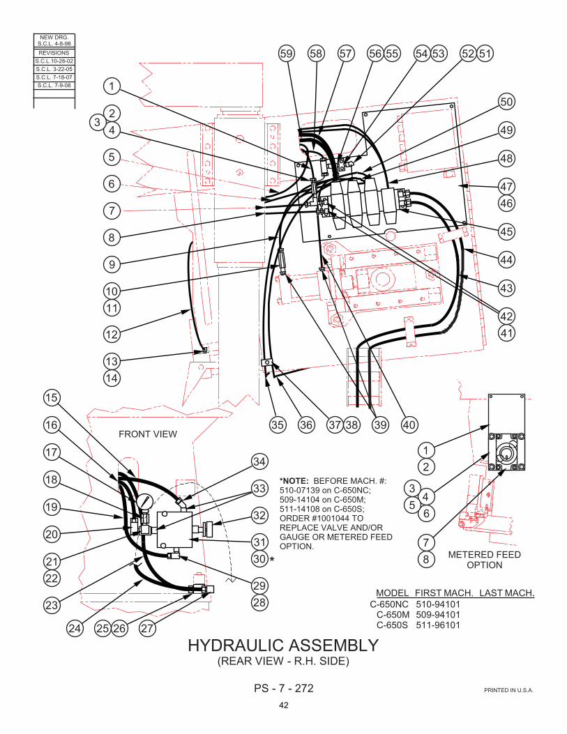
PS - 7 - 272 PRINTED IN U.S.A.
MODEL FIRST MACH. LAST MACH.C-650NC 510-94101
C-650M 509-94101C-650S 511-96101
HYDRAULIC ASSEMBLY(REAR VIEW - R.H. SIDE)
FRONT VIEW
1
23
4
5
6
7
8
9
1011
12
1314
15
16
17
18
19
20
2122
23
24 25 26 27
2829
3031
32
33
34
35 36 37 38 39 40
4142
43
44
45
4647
48
49
50
515253545556575859
METERED FEEDOPTION
12
34
56
78
NEW DRG.S.C.L. 4-8-98
REVISIONSS.C.L.10-28-02S.C.L. 3-22-05S.C.L. 7-18-07
*NOTE: BEFORE MACH. #:510-07139 on C-650NC;509-14104 on C-650M;511-14108 on C-650S;ORDER #1001044 TOREPLACE VALVE AND/ORGAUGE OR METERED FEEDOPTION.
S.C.L. 7-9-08
*
42

CODE NO. PS-7-272 __________ __________
HYDRAULIC ASSEMBLY (Rear View - R.H. Side) INDEX PART DESCRIPTION UNITS PER NO. NO. ASS'Y. Ref. 219797 Hydraulic Assembly (C-650NC) Ref. 206322 Hydraulic Assembly (C-650M) Ref. 209226 Hydraulic Assembly (C-650S) Ref. 219801 Hydraulic Assembly (C-1000/650S) 1 207617 . Hydraulic Hose (#32) ........................... 1 2 140847 . Needle Valve ....................................... 1 3 14-003507 . Close Nipple ........................................ 1 4 120857 . Service Tee .......................................... 1 5 207617 . Hydraulic Hose (#38) ........................... 1 6 207617 . Hydraulic Hose (#1) ............................. 1 7 207617 . Hydraulic Hose (#9) ............................. 1 8 207617 . Hydraulic Hose (#10) ........................... 1 9 207617 . Hydraulic Hose (#2) ............................. 1 10 303411 . Orifice (.025 Dia.) ................................. 1 11 35-002343 . Pipe Nipple .......................................... 1 12 207617 . Hydraulic Hose (#42) ........................... 1 13 5-027506 . 90° Street Elbow .................................. 2 14 003849 . Swivel Adaptor Union .......................... 1 15 207617 . Hydraulic Hose (#9) ............................. 1 16 207617 . Hydraulic Hose (#38) ........................... 1 17* 902164 . Pressure Gauge ................................... 1 18 111543 . Snubber ............................................... 1 19 207617 . Hydraulic Hose (#10) ........................... 1 20 008254 . 90° Street Elbow .................................. 1 21 120857 . Service Tee .......................................... 1 22 008254 . 90° Street Elbow .................................. 1 23 207617 . Hydraulic Hose (#1) ............................. 1 24 207617 . Hydraulic Hose (#42) ........................... 1 25 114433 . Manifold ............................................... 1 26 199997 . Screw, Soc. Hd. Cap M6-1.0 x 80 ....... 2 27 008254 . 90° Street Elbow .................................. 2 28 107222 . Adaptor ................................................ 1 29 008254 . 90° Street Elbow .................................. 1 30* 256116 . Pressure Reducing/Relieving Valve .... 1 31 199758 . Screw, Soc. Hd. Cap M5-0.8 x 60 ....... 2 32 206650 . Knob Kit ............................................... 1 33 107222 . Adaptor ................................................ 2 34 121933 . 45° Street Elbow .................................. 1 35 207617 . Hydraulic Hose (#14) ........................... 1 36 207617 . Hydraulic Hose (#15) ........................... 1 37 313332 . Double Support .................................... 1 38 199662 . Screw, Soc. Hd. Cap M6-1.0 x 25 ....... 1 39 017527 . Reducer Bushing ................................. 2 40 207617 . Hydraulic Hose (#4) ............................. 1 41 120766 . Female Pipe Adaptor ........................... 2 42 017537 . Reducer Bushing ................................. 2 43 207617 . Hydraulic Hose (#18) ........................... 1 44 207617 . Hydraulic Hose (#17) ........................... 1 45 204473 . Head Manifold Assembly (See Detail) . 1
INDEX PART DESCRIPTION UNITS PERNO. NO. ASS'Y. 46 517291 . Mounting Plate ..................................... 1 47 199926 . Screw, Soc. Hd. Cap M8-1.25 x 25 ...... 5 48 207617 . Hydraulic Hose (#11) ........................... 2 49 207617 . Hydraulic Hose (Front) (#15) ................ 1 50 207617 . Hydraulic Hose (Rear) (#14) ................ 1 51 309057 . 90° Male Elbow .................................... 1 52 197130 . Steel Tubing 3/8 O.D. .......................... A.R. 53 114433 . Manifold ............................................... 1 54 199915 . Screw, Soc. Hd. Cap M6-1.0 x 30 ........ 2 55 120857 . Service Tee .......................................... 1 56 161083 . Male Branch Tee .................................. 1 57 207617 . Hydraulic Hose (Front) (#16) ................ 1 58 207617 . Hydrauilic Hose (#3) ............................. 1 59 207617 . Hydraulic Hose (Rear) (#5) .................. 1 Ref.* 221034 Metered Head Feed Option 1 325873 . Mounting Bracket ................................. 1 2 199903 . Screw, Soc. Hd. Cap M8-1.25 x 20 ...... 2 3 154059 . Sub-Plate ............................................. 1 4 199903 . Screw, Soc. Hd. Cap M8-1.25 x 20 ...... 4 5 017537 . Reducer Bushing ................................. 2 6 008254 . 90° Street Elbow .................................. 2 7 166526 . Flow Control Valve ............................... 1 8 198264 . Screw, Soc. Hd. Cap 5/16-18NC x 2 .... 4 *NOTE: Replace With #1001044 Before Machine #: 139 on C-650NC; 104 on C-650M; 108 on C-650S.
43

NEW DRG.S.C.L. 4-8-98
PS - 7 - 273 PRINTED IN U.S.A.
MODEL FIRST MACH. LAST MACH.C-650NC 510-94101C-650M 509-94101 509-05102C-650S 511-96101
HYDRAULIC ASSEMBLY(HEAD MANIFOLD ASSEMBLY)
NOTE: BEFORE SERIAL #510-94108 ON C-650NC,THIS ASSEMBLY WAS ROTATED 90° ANDVALVING MAY VARY FROM WHAT IS SHOWN.
1 2 3 4 5 6 7 8 9
TOP VIEW
10111213141516171819
REVISIONSS.C.L.10-28-02S.C.L. 3-22-05S.C.L. 7-9-08
44

CODE NO. PS-7-273 ____________ ____________
HYDRAULIC ASSEMBLY
(Head Manifold Assembly) INDEX PART DESCRIPTION UNITS PER NO. NO. ASS'Y. Ref. 219797 Hydraulic Assembly (C-650NC) Ref. 206322 Hydraulic Assembly (C-650M) Ref. 209226 Hydraulic Assembly (C-650S) Ref. 219801 Hydraulic Assembly (C-1000/650S) Ref. 204473 Head Manifold Assembly 1 207617 . Hydraulic Hose (#16) ............................................................................. 1 2 207617 . Hydraulic Hose (#5) ............................................................................... 1 3 309010 . Male Connector ...................................................................................... 1 4 207617 . Hydraulic Hose (#4) ............................................................................... 1 5 205065 . O-Ring Adaptor ...................................................................................... 4 6 207617 . Hydraulic Hose (#14) ............................................................................. 1 7 207617 . Hydraulic Hose (#15) ............................................................................. 1 8 205065 . O-Ring Adaptor ...................................................................................... 2 9 207617 . Hydraulic Hose (#11) ............................................................................. 2 10 1001930 . Flow Control Valve ................................................................................. 1 11 1006387 . Directional Control Valve ....................................................................... 1 12 265462 . Check Valve (Pilot Operated) ................................................................ 1 13 1001808 . Flow Control Valve ................................................................................. 1 14 1003596 . Directional Control Valve ....................................................................... 1 15 1003595 . Directional Control Valve ....................................................................... 1 16 265478 . Pressure Reducing/Relieving Valve ...................................................... 1 17 262394 . Check Valve (Pilot Operated) ................................................................ 1 18 1003596 . Directional Control Valve ....................................................................... 1 19 265554 . Pressure Reducing/Relieving Valve ...................................................... 1
45

NEW DRG.S.C.L. 7-13-06
PS - 7 - 367 PRINTED IN U.S.A.
MODEL FIRST MACH. LAST MACH.C-650M 509-06103
HYDRAULIC ASSEMBLY(HEAD MANIFOLD ASSEMBLY)
1 2 3 4 5 6 7 8 9
TOP VIEW
10111213141516171819
REVISIONS
46

CODE NO. PS-7-367 ____________ ____________
HYDRAULIC ASSEMBLY
(Head Manifold Assembly) INDEX PART DESCRIPTION UNITS PER NO. NO. ASS'Y. Ref. 223038 Hydraulic Assembly Ref. 222996 Head Manifold Assembly 1 207617 . Hydraulic Hose (#16) ............................................................................. 1 2 207617 . Hydraulic Hose (#5) ............................................................................... 1 3 309010 . Male Connector ...................................................................................... 1 4 207617 . Hydraulic Hose (#4) ............................................................................... 1 5 205065 . O-Ring Adaptor ...................................................................................... 4 6 207617 . Hydraulic Hose (#14) ............................................................................. 1 7 207617 . Hydraulic Hose (#15) ............................................................................. 1 8 205065 . O-Ring Adaptor ...................................................................................... 2 9 207617 . Hydraulic Hose (#11) ............................................................................. 2 10 262426 . Flow Control Valve ................................................................................. 1 11 263178 . Directional Control Valve ....................................................................... 1 12 262406 . Check Valve (Pilot Operated) ................................................................ 1 13 262420 . Flow Control Valve ................................................................................. 1 14 262977 . Directional Control Valve ....................................................................... 1 15 262997 . Directional Control Valve ....................................................................... 1 16 262479 . Flow Control Valve ................................................................................. 1 17 262394 . Check Valve (Pilot Operated) ................................................................ 1 18 262977 . Directional Control Valve ....................................................................... 1 19 262472 . Pressure Reducing/Relieving Valve ...................................................... 1
47

NEW DRG.S.C.L. 4-8-98
PS - 7 - 274 PRINTED IN U.S.A.
MODEL FIRST MACH. LAST MACH.C-650NC 510-94101
C-650M 509-94101
HYDRAULIC ASSEMBLY(VISES)
1234
5 6 7 8910
INBOARD VISE AREA(ALSO OUTBOARD VISE IF SUPPLIED) 11 12
13
14
15
1617181920212223242526272829303132
33 34 35
3637
38
40 41
INDEXING VISE AREA(C-650NC ONLY)
39
REVISIONSS.C.L.10-28-02S.C.L. 3-23-05S.C.L. 7-9-08
48

CODE NO. PS-7-274 ____________ ____________
HYDRAULIC ASSEMBLY
(Vises) INDEX PART DESCRIPTION UNITS PER NO. NO. ASS'Y. Ref. 219797 Hydraulic Assembly (C-650NC) Ref. 206322 Hydraulic Assembly (C-650M) 1 114878 . Reducer Bushing ................................................................................... 2 2 148887 . 90° Street Elbow .................................................................................... 2 3 017546 . Reducer Bushing ................................................................................... 1 4 148887 . 90° Street Elbow .................................................................................... 1 5 207617 . Hydraulic Hose (#25) ............................................................................. 1 6 207617 . Hydraulic Hose (#24) ............................................................................. 1 7 207617 . Hydraulic Hose (#37) ............................................................................. 1 8 017546 . Reducer Bushing ................................................................................... 1 9 133542 . Service Tee ............................................................................................ 1 10 148887 . 90° Street Elbow .................................................................................... 1 11 207617 . Hydraulic Hose (#37) ............................................................................. 1 12 207617 . Hydraulic Hose (#34) ............................................................................. 1 For C-650NC Only: 13 207617 . Hydraulic Hose (#36) ............................................................................. 1 14 207617 . Hydraulic Hose (#21) ............................................................................. 1 15 202124 . Bulkhead Union ...................................................................................... 2 16 207617 . Hydraulic Hose (#22) ............................................................................. 1 17 008254 . 90° Street Elbow .................................................................................... 1 18 114433 . Manifold .................................................................................................. 1 19 199915 . Screw, Soc. Hd. Cap M6-1.0 X 30 ......................................................... 2 20 309010 . Male Connector ...................................................................................... 1 21 313339 . Double Support ...................................................................................... 3 22 199897 . Screw, Soc. Hd. Cap M8-1.25 x 35 ....................................................... 3 23 207617 . Hydraulic Hose (#30) ............................................................................. 1 24 207617 . Hydraulic Hose (#29) ............................................................................. 1 25 120903 . 90° Street Elbow .................................................................................... 2 26 197130 . Steel Tubing 3/8 O.D. ............................................................................ A.R. 27 313332 . Double Support ...................................................................................... 3 28 199662 . Screw, Soc. Hd. Cap M6-1.0 x 25 ......................................................... 3 29 309010 . Male Connector (If Supplied) ................................................................. 2 30 144360 . Restrictor Valve (If Supplied) ................................................................. 1 31 017546 . Reducer Bushing ................................................................................... 2 32 309059 . 90° Male Elbow ...................................................................................... 2 33 114878 . Reducer Bushing (If Supplied) ............................................................... 2 34 309061 . 90° Male Elbow ...................................................................................... 2 309059 . 90° Male Elbow (Used w/Reducer Bushing) .......................................... 2 35 197130 . Steel Tubing 3/8 O.D. ............................................................................ A.R. 36 015017 . Manifold .................................................................................................. 1 37 199915 . Screw, Soc. Hd. Cap M6-1.0 x 30 ......................................................... 2 38 148887 . 90° Street Elbow .................................................................................... 1 39 148887 . 90° Street Elbow .................................................................................... 1 202597 . Male Branch Tee (Vertical Hold-Down Option) ..................................... 1 40 133542 . Service Tee ............................................................................................ 1 41 309012 . Male Connector ...................................................................................... 2
49

NEW DRG.S.C.L. 4-8-98
PS - 7 - 275 PRINTED IN U.S.A.
MODEL FIRST MACH. LAST MACH.C-650NC 510-94101
C-650M 509-94101 509-05102
HYDRAULIC ASSEMBLY(POWER UNIT)
12345678
9
10
11TYPICAL
12
13
1415
1617
18
19
20
2122 23 24 25
2627
28
2930
31
3233
34
35
36
1213
14
15
16
1718
19
2021
22
2324
25
2627
C-650M POWER UNIT
C-650NC POWER UNIT
REVISIONSS.C.L.10-28-02S.C.L. 3-23-05S.C.L. 7-9-08
50

CODE NO. PS-7-275 ____________ ____________
HYDRAULIC ASSEMBLY
(Power Unit) INDEX PART DESCRIPTION UNITS PER NO. NO. ASS'Y. Ref. 219797 Hydraulic Assembly (C-650NC) Ref. 206322 Hydraulic Assembly (C-650M) Ref. 204768 Power Unit (C-650NC) Ref. 204471 Power Unit (C-650M) 1 . Filter (Fleet Guard, #HH-6928) .................................................................................................................... 1 2 204469 . Filter Element .............................................................................................................................................. 1 3 120903 . 90º Street Elbow .......................................................................................................................................... 1 4 207617 . Hydraulic Hose (#18) ................................................................................................................................... 1 5 133540 . Service Tee ................................................................................................................................................. 1 6 207617 . Hydraulic Hose (#35) ................................................................................................................................... 1 7 207840 . Electric Motor (C-650NC) ............................................................................................................................ 1 207839 . Electric Motor (C-650M) .............................................................................................................................. 1 8 156459 . Hydraulic Pump (PVR6) .............................................................................................................................. 1 9 309662 . Escutcheon (Warning) ................................................................................................................................. 1 10 201180 . Escutcheon (ATF Specifications) ................................................................................................................ 1 11 199926 . Screw, Soc. Hd. Cap M8-1.25 x 25 ............................................................................................................. 4 For C-650NC Power Unit: 12 144698 . Pipe Plug ..................................................................................................................................................... 2 13 207617 . Hydraulic Hose (#17) ................................................................................................................................... 1 14 205065 . Pipe Adaptor ................................................................................................................................................ 2 15 207617 . Hydraulic Hose (#19) ................................................................................................................................... 2 16 133542 . Service Tee ................................................................................................................................................. 1 17 207617 . Hydraulic Hose (#22) ................................................................................................................................... 1 18 207617 . Hydraulic Hose (#21) ................................................................................................................................... 1 19 207617 . Hydraulic Hose (#23) ................................................................................................................................... 1 20 207617 . Hydraulic Hose (#24) ................................................................................................................................... 1 21 207617 . Hydraulic Hose (#27) ................................................................................................................................... 1 22 207617 . Hydraulic Hose (#26) ................................................................................................................................... 1 23 207617 . Hydraulic Hose (#27) ................................................................................................................................... 1 24 133542 . Service Tee ................................................................................................................................................. 1 25 207617 . Hydraulic Hose (#25) ................................................................................................................................... 1 26 261142 . Proportional Directional Control Valve ........................................................................................................ 1 27 198225 . Screw, Soc. Hd. Cap #10-24NC x 1 ............................................................................................................ 4 28 012144 . Washer, Lock #10 Hi-Collar ......................................................................................................................... 4 29 1003596 . Directional Control Valve ............................................................................................................................. 2 30 198225 . Screw, Soc. Hd. Cap #10-24NC x 1 ............................................................................................................ 8 31 012144 . Washer, Lock #10 Hi-Collar ......................................................................................................................... 8 32 1005914 . Directional Control Valve ............................................................................................................................. 1 33 199658 . Screw, Soc. Hd. Cap #10-24NC x 2-1/2 ...................................................................................................... 4 34 012144 . Washer, Lock #10 Hi-Collar ......................................................................................................................... 4 35 1001930 . Flow Control Valve ...................................................................................................................................... 1 36 351702AB . Cover Plate .................................................................................................................................................. 1 For C-650M Power Unit: 12 144698 . Pipe Plug (Standard) ................................................................................................................................... 2 205065 . Pipe Adaptor (Chip Conveyor Option) ......................................................................................................... 2 13 207617 . Hydraulic Hose (#19) (Chip Conveyor Option) ............................................................................................ 2 14 207617 . Hydraulic Hose (#17) ................................................................................................................................... 1 15 144698 . Pipe Plug (Standard) ................................................................................................................................... 2 206515 . Hydraulic Hose (Outboard Vise Option) ...................................................................................................... 2 16 207617 . Hydraulic Hose (#23) ................................................................................................................................... 2 17 1003596 . Directional Control Valve ............................................................................................................................. 1 18 198225 . Screw, Soc. Hd. Cap #10-24NC x 1 ............................................................................................................ 4 19 012144 . Washer, Lock #10 Hi-Collar ......................................................................................................................... 4 20 1003596 . Directional Control Valve (Outboard Vise Option) ....................................................................................... 1 21 198225 . Screw, Soc. Hd. Cap #10-24NC x 1 (Outboard Vise Option) ...................................................................... 4 22 012144 . Washer, Lock #10 Hi-Collar ......................................................................................................................... 4 23 1005914 . Directional Control Valve (Chip Conveyor Option) ...................................................................................... 1 24 199658 . Screw, Soc. Hd. Cap #10-24NC x 2-1/2 (Chip Conveyor Option) ............................................................... 4 25 012144 . Washer, Lock #10 Hi-Collar ......................................................................................................................... 4 26 1001930 . Flow Control Valve (Chip Conveyor Option) ................................................................................................ 1 27 351702AB . Cover Plate (Standard) ................................................................................................................................ 2 Following Not Shown: 201030 . Transmission Fluid ....................................................................................................................................... A.R.
51

NEW DRG.S.C.L. 7-13-06
PS - 7 - 368 PRINTED IN U.S.A.
MODEL FIRST MACH. LAST MACH.C-650M 509-06103
HYDRAULIC ASSEMBLY(POLYPAC POWER UNIT)
12345678
9
10
11TYPICAL
1213
14
15
16
1718
19
2021
22
2324
25
2627
REVISIONS
52

CODE NO. PS-7-368 ____________ ____________
HYDRAULIC ASSEMBLY (Polypac Power Unit)
INDEX PART DESCRIPTION UNITS PER NO. NO. ASS'Y. Ref. 223038 Hydraulic Assembly Ref. 223037 Hydraulic Power Unit 1 . Filter (Fleet Guard, #HH-6928) .............................................................. 1 2 204469 . Filter Element ......................................................................................... 1 3 120903 . 90º Street Elbow .................................................................................... 1 4 207617 . Hydraulic Hose (#18) ............................................................................. 1 5 133540 . Service Tee ............................................................................................ 1 6 207617 . Hydraulic Hose (#35) ............................................................................. 1 7 974561 . Electric Motor .......................................................................................... 1 8 156459 . Hydraulic Pump (PVR6) ......................................................................... 1 9 309662 . Escutcheon (Warning) ........................................................................... 1 10 201180 . Escutcheon (ATF Specifications) (Access Door) .................................. 1 11 199926 . Screw, Soc. Hd. Cap M8 x 1.25 x 25 ..................................................... 4 12 144698 . Pipe Plug (Standard) .............................................................................. 2 205065 . Pipe Adaptor (Chip Conveyor Option) ................................................... 2 13 207617 . Hydraulic Hose (#19) (Chip Conveyor Option) ...................................... 2 14 207617 . Hydraulic Hose (#17) ............................................................................. 1 15 144698 . Pipe Plug (Standard) .............................................................................. 2 206515 . Hydraulic Hose (Outboard Vise Option) ................................................ 2 16 207617 . Hydraulic Hose (#26) ............................................................................. 2 17 262977 . Directional Control Valve ....................................................................... 1 18 198225 . Screw, Soc. Hd. Cap #10-24NC x 1 ...................................................... 4 19 012144 . Washer, Lock #10 Hi-Collar ................................................................... 4 20 262977 . Directional Control Valve (Outboard Vise Option) ................................. 1 21 198225 . Screw, Soc. Hd. Cap #10-24NC x 1 (Outboard Vise Option) ................ 4 22 012144 . Washer, Lock #10 Hi-Collar ................................................................... 4 23 263911 . Directional Control Valve (Chip Conveyor Option) ................................ 1 24 199658 . Screw, Soc. Hd. Cap #10-24NC x 2-1/2 (Chip Conveyor Option) ......... 4 25 012144 . Washer, Lock #10 Hi-Collar ................................................................... 4 26 262426 . Flow Control Valve (Chip Conveyor Option) .......................................... 1 27 210721 . Cover Plate (Standard) .......................................................................... 2 Following Not Shown: 201030 . Transmission Fluid .................................................................................. A.R.
53

PS - 7 - 276 PRINTED IN U.S.A.
MODEL FIRST MACH. LAST MACH.C-650NC 510-94101
C-650M 509-94101
HYDRAULIC ASSEMBLY(VARIABLE VISE PRESSURE)
1
2
3
45
6
7
8
9
10
11
1213
14
15
16
17
1819
2021
22
23
24
2526
27
28
29
30
3132
33
34
35
3637
38
NEW DRG.S.C.L. 4-8-98REVISIONS
S.C.L.10-28-02S.C.L. 3-23-05S.C.L. 7-9-08
54
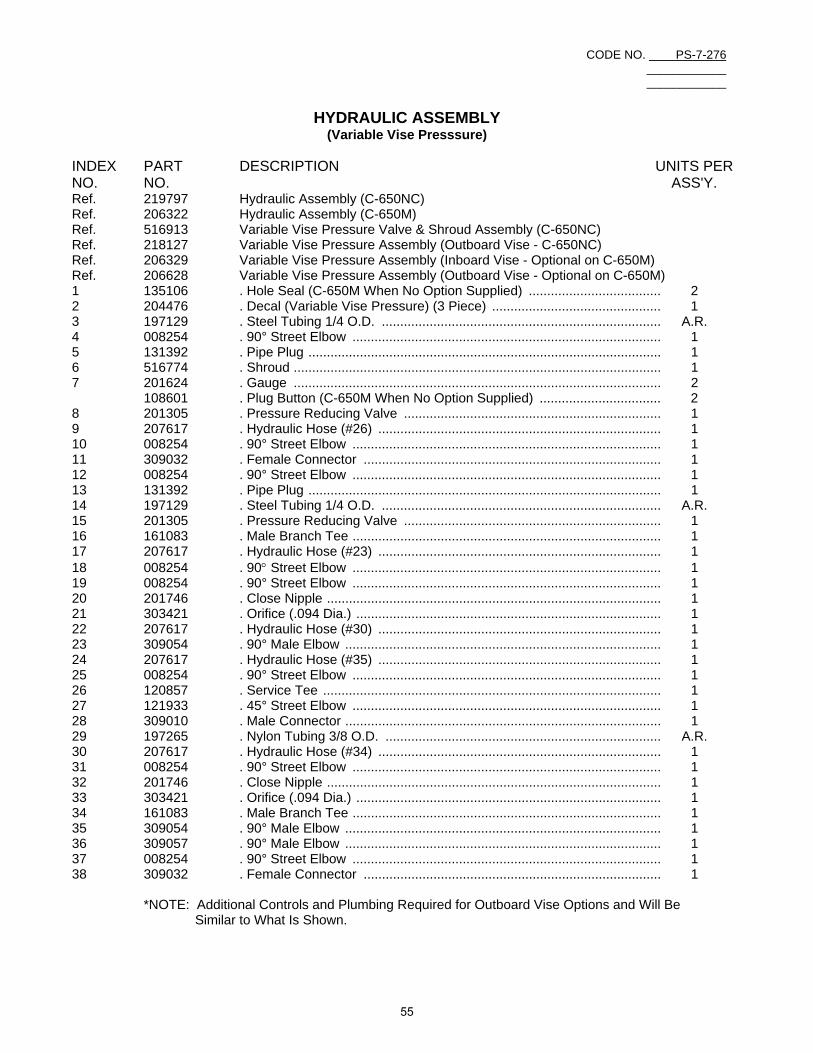
CODE NO. PS-7-276 ____________ ____________
HYDRAULIC ASSEMBLY
(Variable Vise Presssure) INDEX PART DESCRIPTION UNITS PER NO. NO. ASS'Y. Ref. 219797 Hydraulic Assembly (C-650NC) Ref. 206322 Hydraulic Assembly (C-650M) Ref. 516913 Variable Vise Pressure Valve & Shroud Assembly (C-650NC) Ref. 218127 Variable Vise Pressure Assembly (Outboard Vise - C-650NC) Ref. 206329 Variable Vise Pressure Assembly (Inboard Vise - Optional on C-650M) Ref. 206628 Variable Vise Pressure Assembly (Outboard Vise - Optional on C-650M) 1 135106 . Hole Seal (C-650M When No Option Supplied) .................................... 2 2 204476 . Decal (Variable Vise Pressure) (3 Piece) .............................................. 1 3 197129 . Steel Tubing 1/4 O.D. ............................................................................ A.R. 4 008254 . 90° Street Elbow .................................................................................... 1 5 131392 . Pipe Plug ................................................................................................ 1 6 516774 . Shroud .................................................................................................... 1 7 201624 . Gauge .................................................................................................... 2 108601 . Plug Button (C-650M When No Option Supplied) ................................. 2 8 201305 . Pressure Reducing Valve ...................................................................... 1 9 207617 . Hydraulic Hose (#26) ............................................................................. 1 10 008254 . 90° Street Elbow .................................................................................... 1 11 309032 . Female Connector ................................................................................. 1 12 008254 . 90° Street Elbow .................................................................................... 1 13 131392 . Pipe Plug ................................................................................................ 1 14 197129 . Steel Tubing 1/4 O.D. ............................................................................ A.R. 15 201305 . Pressure Reducing Valve ...................................................................... 1 16 161083 . Male Branch Tee .................................................................................... 1 17 207617 . Hydraulic Hose (#23) ............................................................................. 1 18 008254 . 90° Street Elbow .................................................................................... 1 19 008254 . 90° Street Elbow .................................................................................... 1 20 201746 . Close Nipple ........................................................................................... 1 21 303421 . Orifice (.094 Dia.) ................................................................................... 1 22 207617 . Hydraulic Hose (#30) ............................................................................. 1 23 309054 . 90° Male Elbow ...................................................................................... 1 24 207617 . Hydraulic Hose (#35) ............................................................................. 1 25 008254 . 90° Street Elbow .................................................................................... 1 26 120857 . Service Tee ............................................................................................ 1 27 121933 . 45° Street Elbow .................................................................................... 1 28 309010 . Male Connector ...................................................................................... 1 29 197265 . Nylon Tubing 3/8 O.D. ........................................................................... A.R. 30 207617 . Hydraulic Hose (#34) ............................................................................. 1 31 008254 . 90° Street Elbow .................................................................................... 1 32 201746 . Close Nipple ........................................................................................... 1 33 303421 . Orifice (.094 Dia.) ................................................................................... 1 34 161083 . Male Branch Tee .................................................................................... 1 35 309054 . 90° Male Elbow ...................................................................................... 1 36 309057 . 90° Male Elbow ...................................................................................... 1 37 008254 . 90° Street Elbow .................................................................................... 1 38 309032 . Female Connector ................................................................................. 1 *NOTE: Additional Controls and Plumbing Required for Outboard Vise Options and Will Be Similar to What Is Shown.
55

PS - 9 - 168 PRINTED IN U.S.A.
MODEL FIRST MACH. LAST MACH.C-650NC 510-94101
C-650M 509-94101C-650S 511-96101
HYDRAULIC ASSEMBLY(VERTICAL HOLD DOWN OPTION)
OUTBOARD VISE(FRONT VIEW)
INBOARD VISE(REAR VIEW)
INDEX VISE(SIDE VIEW)
(C-650NC ONLY)
1234
6 7 8 9
1011
12 1314
15
16 17
1819
20 2122
2324
25 26 27
28
29
30 31
32333435
3637
3839
40 41 42 43
4445
4647
48
4950
51
5253
54
55
5657
58
59
60
61
62
63
64
6566
5
NEW DRG.S.C.L. 8-26-99
REVISIONSS.C.L. 3-23-05S.C.L. 7-9-08
56

CODE NO. PS-9-168 ____________ ____________
HYDRAULIC ASSEMBLY (Vertical Hold-Down Option)
INDEX PART DESCRIPTION UNITS PER NO. NO. ASS'Y. Ref. Hydraulic Assembly (Vertical Hold-Down Option) 1 5-011517 . Reducer Bushing ......................................................................................................................................... 2 2 14-003507 . Close Nipple ................................................................................................................................................ 1 3 144360 . Restrictor Valve ........................................................................................................................................... 1 4 017537 . Reducer Bushing ......................................................................................................................................... 1 5 133540 . Street Tee .................................................................................................................................................... 1 6 197130 . Steel Tubing 3/8 O.D. .................................................................................................................................. A.R. 7 309057 . 90° Male Elbow ............................................................................................................................................ 1 8 309010 . Male Connector .......................................................................................................................................... 1 9 205660 . Needle Valve ............................................................................................................................................... 1 10 015017 . Manifold ....................................................................................................................................................... 1 11 199619 . Screw, Soc. Hd. Cap M6-1.0 x 35 ............................................................................................................... 2 12 207618 . Hydraulic Hose (#108) ................................................................................................................................. 1 13 313339 . Double Support ............................................................................................................................................ 1 14 199619 . Screw, Soc. Hd. Cap M6-1.0 x 35 ............................................................................................................... 1 15 207618 . Hydraulic Hose ............................................................................................................................................ 1 16 148887 . 90° Street Elbow .......................................................................................................................................... 2 17 148887 . 90° Street Elbow .......................................................................................................................................... 2 18 207618 . Hydraulic Hose (#105) ................................................................................................................................. 1 19 114878 . Reducer Bushing (Cylinder) ........................................................................................................................ 1 20 207618 . Hydraulic Hose (#108) ................................................................................................................................. 1 21 313339 . Double Support ............................................................................................................................................ 1 22 199619 . Screw, Soc. Hd. Cap M6-1.0 x 35 ............................................................................................................... 1 23 015017 . Manifold ....................................................................................................................................................... 1 24 208472 . Spacer ......................................................................................................................................................... 1 25 199086 . Screw, Soc. Hd. Cap M6-1.0 x 60 ............................................................................................................... 2 26 205660 . Needle Valve ............................................................................................................................................... 1 27 207618 . Hydraulic Hose (#107) ................................................................................................................................. 1 28 197130 . Steel Tubing 3/8 O.D. .................................................................................................................................. A.R. 29 309010 . Male Connector ........................................................................................................................................... 1 30 114878 . Reducer Bushing ......................................................................................................................................... 1 31 133540 . Street Tee .................................................................................................................................................... 1 32 309010 . Male Connector ........................................................................................................................................... 1 33 144360 . Restrictor Valve ........................................................................................................................................... 1 34 14-003507 . Close Nipple ................................................................................................................................................ 1 35 5-011517 . Reducer Bushing ......................................................................................................................................... 2 36 001547 . Reducer Coupling ........................................................................................................................................ 1 37 14-003507 . Close Nipple ................................................................................................................................................ 1 38 114433 . Manifold ....................................................................................................................................................... 1 39 199619 . Screw, Soc. Hd. Cap M6-1.0 x 35 ............................................................................................................... 2 40 148887 . 90° Street Elbow .......................................................................................................................................... 1 41 202597 . Male Branch Tee ......................................................................................................................................... 1 42 207618 . Hydraulic Hose (#104) ................................................................................................................................. 1 43 207618 . Hydraulic Hose (#109) ................................................................................................................................. 1 44 35-002344 . Pipe Nipple .................................................................................................................................................. 2 45 120905 . 90° Elbow .................................................................................................................................................... 1 46 017537 . Reducer Bushing ......................................................................................................................................... 1 47 008254 . 90° Street Elbow .......................................................................................................................................... 1 48 207618 . Hydraulic Hose (#109) ................................................................................................................................. 1 49 144360 . Restrictor Valve ........................................................................................................................................... 1 50 14-003507 . Close Nipple ................................................................................................................................................ 1 51 5-011517 . Reducer Bushing ......................................................................................................................................... 1 52 015017 . Manifold ....................................................................................................................................................... 1 53 199619 . Screw, Soc. Hd. Cap M6-1.0 x 35 ............................................................................................................... 2 54 207618 . Hydraulic Hose (#103) ................................................................................................................................. 1 55 008254 . 90° Street Elbow .......................................................................................................................................... 1 56 166980 . Pilot Operated Check Valve ........................................................................................................................ 1 57 207618 . Hydraulic Hose (#101) ................................................................................................................................. 1 58 008254 . 90° Street Elbow .......................................................................................................................................... 1 59 207618 . Hydraulic Hose (#102) ................................................................................................................................. 1 60 133542 . Street Tee .................................................................................................................................................... 1 61 148887 . 90° Street Elbow .......................................................................................................................................... 1 62 5-011517 . Reducer Bushing ......................................................................................................................................... 1 63 205660 . Needle Valve ............................................................................................................................................... 1 64 207618 . Hydraulic Hose (#104) ................................................................................................................................. 1 65 313339 . Double Support ............................................................................................................................................ 1 66 199619 . Screw, Soc. Hd. Cap M6-1.0 x 35 ............................................................................................................... 2
57

NEW DRG.S.C.L. 7-15-07
REVISIONS
PS - 7 - 373 PRINTED IN U.S.A.
MODEL FIRST MACH. LAST MACH.C-650NC 510-07139
C-650M 509-07104C-650S 511-07108
HYDRAULIC CONTROL PANEL ASSEMBLY
FEED RATE CONTROLVALVE SUB-ASSEMBLY
1 2 3 4 5 6
7
8910111213
1 2 3 4 5 67
8
910
11
12
13
1415
16
17
1819
2021
22232425262728
2930
31
32
33
34
35
36
S.C.L. 7-9-08
58

CODE NO. PS-7-373 ____________ ____________
HYDRAULIC CONTROL PANEL ASSEMBLY
INDEX PART DESCRIPTION UNITS PER NO. NO. ASS'Y. Ref. 1001036 Hydraulic Control Panel Assembly 1 309054 . 90° Male Elbow .................................................................................................. 1 2 105053 . 90° Street Elbow ................................................................................................ 1 3 207617 . Hydraulic Hose (#7) ........................................................................................... 1 4 1001042 . Bracket ............................................................................................................... 2 5 317966 . Feed Rate Control Valve Sub-Assembly (See Detail) ....................................... 1 6 198007 . Screw, Hex. Hd. Cap 1/4-20NC x 5/8 ................................................................ 2 7 199321 . Washer, Lock 1/4 Std. ........................................................................................ 2 8 199260 . Washer, Flat 1/4 S.A.E. Std. .............................................................................. 2 9 198349 . Screw, Button Hd. Soc. 1/4-20NC x 1/2 ............................................................ 2 10 199115 . Nut, Hex. 1/4-20NC ............................................................................................ 2 11 199321 . Washer, Lock 1/4 Std. ........................................................................................ 2 12 318035 . Bracket ............................................................................................................... 1 13 207617 . Hydraulic Hose (#10) ......................................................................................... 1 14 198349 . Screw, Button Hd. Soc. 1/4-20NC x 1/2 ............................................................ 2 15 199115 . Nut, Hex. 1/4-20NC ............................................................................................ 2 16 199321 . Washer, Lock 1/4 Std. ........................................................................................ 2 17 318033 . Bracket ............................................................................................................... 1 18 198012 . Screw, Hex. Hd. Cap 1/4-20NC x 1-1/2 ............................................................. 2 19 199115 . Nut, Hex. 1/4-20NC ............................................................................................ 2 20 199321 . Washer, Lock 1/4 Std. ........................................................................................ 2 21 199260 . Washer, Flat 1/4 S.A.E. Std. .............................................................................. 2 22 008254 . 90° Street Elbow ................................................................................................ 1 23 111543 . Pressure Snubber .............................................................................................. 1 24 309005 . Male Connector .................................................................................................. 1 25 197129 . Steel Tubing 1/4 O.D. ........................................................................................ A.R. 26 309122 . Male Run Tee .................................................................................................... 1 27 303411 . Orifice (.025) ...................................................................................................... 1 28 120857 . Service Tee (Brass) ........................................................................................... 1 29 198349 . Screw, Button Hd. Soc. 1/4-20NC x 1/2 ............................................................ 4 30 199115 . Nut, Hex. 1/4-20NC ............................................................................................ 4 31 199321 . Washer, Lock 1/4 Std. ........................................................................................ 4 32 325879 . Escutcheon Back Plate ...................................................................................... 1 33 176012 . Knob ................................................................................................................... 1 34 325885 . Escutcheon ........................................................................................................ 1 35 1001038 . Relief Valve ........................................................................................................ 1 36 318837 . Gauge ................................................................................................................ 1 Ref. 317966 . Feed Rate Control Valve Sub-Assembly 1 109411 . . O-Ring ............................................................................................................... 1 2 . . Spool (Order Complete Valve Assembly) ......................................................... 1 3 . . Valve Body (Order Complete Valve Assembly) .................................................. 1 4 108936 . . Compression Spring ............................................................................................ 1 5 109411 . . O-Ring ................................................................................................................. 1 6 003019 . . O-Ring ................................................................................................................. 1 7 318356 . . Valve Stem .......................................................................................................... 1 8 417601 . . Stem Cap ............................................................................................................ 1 9 198225 . . Screw, Soc. Hd. Cap #10-24NC x 1 ................................................................... 4 10 198218 . . Screw, Soc. Hd. Cap #10-24NC x 1/4 ................................................................ 1 11 001435 . . Copper Washer ................................................................................................... 1 12 319986 . . End Cap .............................................................................................................. 1 13 198219 . . Screw, Soc. Hd. Cap #10-24NC x 3/8 ................................................................ 4
59

NEW DRG.S.C.L. 5-29-00
REVISIONS
C - 10 - 61 CM - 10 - 38 PS - 10 - 87 TF - 5 - 58 Z - 10 - 31 PRINTED IN U.S.A.
LASER LINE GENERATOR ASSEMBLY
TYPICALLY MOUNTED ONTHE SAWING HEAD.
THIS A TYPICAL SET-UP OF THE LASER.SOME PARTS MAY OR MAY NOT APPLYTO YOUR MACHINE.
SELECTOR SWITCH IS MOUNTED ON ORNEAR THE CONTROL PANEL OR ON ASEPERATE CONTROL BOX.
1
2
3
4
5
6
7
8
10 11 1213
14 15 16 17 18 19 20
2122
23 24 25 26 27
S.C.L. 1-15-98S.C.L. 1-25-05
9 or
S.C.L. 11-8-06
60

CODE NO. C-10-61 CM-10-38 PS-10-87
TF-5-58 Z-10-31
LASER LINE GENERATOR ASSEMBLY INDEX PART DESCRIPTION UNITS PER NO. NO. ASS'Y. Ref. Laser Line Generator Assembly 1 212884 . Label (Caution - Laser) .......................................................................... 1 2 212111 . Laser (.67 Dia.) ...................................................................................... 1 214973 . Laser (.75 Dia.) ...................................................................................... 1 220913 . Laser (Square) ....................................................................................... 1 3 213129 . Plate Weldment ...................................................................................... 1 4 199431 . Screw, Soc. Set M5-0.8 x 16 (Dog Pt.) .................................................. 3 5 322650 . Holder ..................................................................................................... 1 6 199993 . Screw, Soc. Hd. Cap M6-1.0 x 20 ......................................................... 3 7 199966 . Screw, Soc. Hd. Cap M6-1.0 x 16 ......................................................... 2 8 216192 . Mounting Bracket (TF-2025 Series) ....................................................... 1 323646 . Mounting Bracket Weldment (C-305 Series) ......................................... 1 9 221012 . Mounting Bracket ................................................................................... 1 10 197332 . Electrical Cord (#18-2 Conductor) ......................................................... A.R. 209820 . Electrical Cord (#24-4 Conductor) ......................................................... A.R. 11 201686 . Cord Grip Connector (.157-.314) ........................................................... 1 201688 . Cord Grip Connector (.200-.394) ........................................................... 1 12 202909 . Fuse Holder ........................................................................................... 1 13 201477 . End Section ............................................................................................ 1 14 211977 . Fuse (2 Amp) ......................................................................................... 1 15 169674 . Mounting Channel .................................................................................. A.R. 16 200618 . End Stop ................................................................................................ 4 17 200615 . Terminal Block ....................................................................................... 3 18 200617 . End Section ............................................................................................ 1 19 209033 . Terminal Block ....................................................................................... 3 20 209034 . End Section ............................................................................................ 1 21 134966 . Junction Box (10 x 8 x 4) ....................................................................... 1 012180 . Junction Box (12 x 10 x 5) .................................................................... 1 136047 . Junction Box (6 x 6 x 4) ......................................................................... 1 22 134967 . Panel (For 10 x 8 x 4 Box) ..................................................................... 1 136386 . Panel (For 12 x 10 x 5 Box) ................................................................... 1 220923 . Panel (For 6 x 6 x 4 Box) ....................................................................... 1 23 197332 . Electrical Cord (#18-2 Conductor) ......................................................... A.R. 209820 . Electrical Cord (#24-4 Conductor) ......................................................... A.R. 24 201686 . Cord Grip Connector (.157-.314) ........................................................... 1 201688 . Cord Grip Connector (.200-.394) ........................................................... 1 25 211111 . Selector Switch Assembly (2 Position) .................................................. 1 26 217700 . Escutcheon (Laser) ................................................................................ 1 27 002992 . Junction Box (4 x 4 x 2) ......................................................................... 1 208075 . Pushbutton Box ...................................................................................... 1 Following Not Shown: 201450 . Power Supply ......................................................................................... 1 202922 . Jumper Bar ............................................................................................. 1 207752 . Cable Tie Mount ..................................................................................... 4 197325 . Wire, #16 White (19 Strand) .................................................................. A.R. 197197 . Wire, #16 Red (19 Strand) ..................................................................... A.R. 215909 . Field Alignment and Adjustment Summary (Laser Installation) ............. 1
61

PS - 6 - 58 PRINTED IN U.S.A.
MODEL FIRST MACH. LAST MACH.C-650NC 510-94101
C-650M 509-94101C-650S 511-96101C-820M 530-96101
C-820NC 531-96101
MIST LUBRICATOR ASSEMBLY
To Lubricator
Right RearColumn Support
Column
To Nozzles
Head Weldment
ACCU-LUBESYSTEM
Head Weldment
To Nozzles
UNISTSYSTEM
1234
5
6
7
8 9
TYPICAL - EITHER SYSTEM
12
3
45
111213
NEW DRG.S.C.L. 8-15-01
REVISIONSS.C.L. 3-18-05S.C.L. 7-9-08
62

CODE NO. PS-6-58 ____________ ____________
MIST LUBRICATOR ASSEMBLY
INDEX PART DESCRIPTION UNITS PER NO. NO. ASS'Y. Ref. 215178 Mist Lubricator Assembly (Unist System) 1 112043 . Street Tee ............................................................................................. 1 2 309004 . Male Connector ..................................................................................... 1 3 199818 . Screw, Soc. Hd. Cap M10-1.5 x 20 ...................................................... 6 4 197129 . Steel Tubing 1/4 O.D. ........................................................................... A.R. 5 309000 . Male Connector ..................................................................................... 1 6 5-027506 . 90° Street Elbow ................................................................................... 1 7 325204 . Lubricator Mounting Bracket ................................................................. 1 8 199051 . Screw, Soc. Hd. Cap M6-1.0 x 12 ........................................................ 4 9 215045 . Mist Lubricator (Unist) (Includes Hoses, Nozzles, etc.) ........................ 1 Ref. 211017 Mist Lubricator Assembly (Accu-Lube System) 1 199993 . Screw, Soc. Hd. Cap M6-1.0 x 20 ........................................................ 3 2 204206 . Mist Lubricator (Accu-Lube) (Includes Hoses, Nozzles, etc.) ............... 1 3 323566 . Bracket .................................................................................................. 1 4 008254 . 90° Street Elbow ................................................................................... 1 5 002004 . Barbed Insert ........................................................................................ 1 For Either System: 11 213583 . Manifold Mounting Plate ....................................................................... 1 12 321375 . Manifold ................................................................................................. 1 13 199051 . Screw, Soc. Hd. Cap M6-1.0 x 12 ........................................................ 6
63

PS - 9 - 204 PRINTED IN U.S.A.
MODEL FIRST MACH. LAST MACH.C-650NC 510-94101
C-650M 509-94101
OUTBOARD VISE ASSEMBLY
123456
7
8 9 10 11 12 13 14
1516171819
20
21
2223 24
25
MOVABLE VISE JAW
NEW DRG.S.C.L. 4-8-99
REVISIONSS.C.L. 3-25-05S.C.L. 7-9-08
64

CODE NO. PS-9-204 ____________ ____________
OUTBOARD VISE ASSEMBLY
INDEX PART DESCRIPTION UNITS PER NO. NO. ASS'Y. Ref. 204862 Outboard Vise Assembly 1 199931 . Screw, Soc. Hd. Cap M16-2.0 x 60 ....................................................... 4 2 516601 . Fixed Jaw ............................................................................................... 1 3 204467 . Key ......................................................................................................... 1 4 516603 . Movable Jaw .......................................................................................... 1 5 517189 . Cylinder Mounting Weldment ................................................................. 1 6 199957 . Dowel Pin ............................................................................................... 4 7 199904 . Screw, Soc. Hd. Cap M12-1.75 x 40 ..................................................... 6 8 417854 . Outboard Vise Clamp Cylinder .............................................................. 1 9 199979 . Screw, Soc. Hd. Cap M12-1.75 x 70 ..................................................... 2 10 204462 . Alignment Coupler ................................................................................. 1 11 417545 . Strike Bar ............................................................................................... 1 12 199903 . Screw, Soc. Hd. Cap M8-1.25 x 20 ....................................................... 2 13 516827 . Wear Plate (2 Each Jaw) ....................................................................... 4 14 199946 . Screw, Soc, Hd. Cap M8-1.25 x 20 (Low Head) .................................... 12 15 205078 . Jaw Wiper .............................................................................................. 1 16 199974 . Screw, Button . Hd. Soc. M5-0.8 x 10 .................................................... 3 17 207151 . Jaw Wiper (If Supplied) .......................................................................... 1 18 199974 . Screw, Button Hd. Soc. M5-0.8 x 10 (If Supplied) ................................. 2 19 199918 . Screw, Soc. Hd. Cap M12-1.75 x 45 ..................................................... 2 20 199947 . Screw, Soc. Hd. Cap 1-14NF x 2.5 ........................................................ 1 21 319485 . Vise Gib .................................................................................................. 1 22 199944 . Screw, Soc. Set M10-1.5 x 45 .............................................................. 4 23 199976 . Nut, Hex. Jam M10-1.5 .......................................................................... 4 24 199742 . Screw, Soc. Hd. Cap M12-1.75 x 35 ..................................................... 6 25 319812 . Way Plate ............................................................................................... 2 Following Not Shown: 218353 . Bracket (Limit Switch) ............................................................................ 1 1003596 . Directional Control Valve (Power Unit) .................................................. 1
65

��������
���� �����
�������
����������� ������������ �
����������������������������
������ ����� ��� ���������
� �! ��������������!�"
����������
� � � � � # � � �� �� �� ��
�
��
��
�# �� �� ��
����
��
� �����#��������
��
��
�
�����#���� � � �
����������"�����������!��������� ���!��������
� �!�����
������������!���$�"���!��������
�����������
��������
��!�����
������������ �"��� ��� !����������
� �!��������!���$�"����������
��������
������� ��!�������� �"��� ���
��������
66

CODE NO. PS-8-321 ____________ ____________
PUSHBUTTON PANEL ASSEMBLY
INDEX PART DESCRIPTION UNITS PER NO. NO. ASS'Y. Ref. Pushbutton Panel Assembly 1 203362 . Display Unit ............................................................................................ 1 2 207396 . Circuit Board .......................................................................................... 1 3 203361 . Potentiometer ......................................................................................... 1 4 178146 . Knob ....................................................................................................... 1 5 178149 . Selector Switch (2 Position) ................................................................... 1 6 179251 . Contact Block (1-NO) ............................................................................. 1 7 178159 . Selector Switch (3 Position) ................................................................... 1 8 177002 . Contact Block (1-NO, 1-NC) .................................................................. 1 9 178149 . Selector Switch (2 Position) ................................................................... 1 10 179251 . Contact Block (1-NO) ............................................................................. 1 11 178159 . Selector Switch (3 Position) ................................................................... 1 12 177002 . Contact Block (1-NO, 1-NC) .................................................................. 1 13 176998 . Pushbutton Operator (Illuminous Green) ............................................... 1 14 179251 . Contact Block (1-NO) ............................................................................. 1 15 177987 . Power Source ........................................................................................ 1 16 205115 . Seal Boot ................................................................................................ 1 17 178149 . Selector Switch (2 Position) ................................................................... 1 18 175561 . Contact Block (1-NO) ............................................................................. 1 19 178159 . Selector Switch (3 Position) ................................................................... 1 20 177002 . Contact Block (1-NO, 1-NC) .................................................................. 1 21 517326 . Escutcheon ............................................................................................ 1 22 179248 . Pushbutton Operator (Red Mushroom) ................................................. 1 23 175562 . Contact Block (1-NC) ............................................................................. 1 24 202902 . E-Stop Marker (Yellow) .......................................................................... 1 25 178154 . Pushbutton Operator (Red) ................................................................... 1 26 175562 . Contact Block (1-NC) ............................................................................. 1 27 178159 . Selector Switch (3 Position) ................................................................... 1 28 177002 . Contact Block (1-NO, 1-NC) .................................................................. 1 29 178159 . Selector Switch (3 Position) ................................................................... 1 30 177002 . Contact Block (1-NO, 1-NC) .................................................................. 1 31 176998 . Pushbutton Operator (Illuminous Green) ............................................... 1 32 179251 . Contact Block (1-NO) ............................................................................. 1 33 177987 . Power Source ........................................................................................ 1 34 205115 . Seal Boot ................................................................................................ 1 35 178154 . Pushbutton Operator (Red) ................................................................... 1 36 175562 . Contact Block (1-NC) ............................................................................. 1 37 178159 . Selector Switch (3 Position) ................................................................... 1 38 177002 . Contact Block (1-NO, 1-NC) .................................................................. 1 39 203455 . Joystick Operator ................................................................................... 1 40 177004 . Contact Block (2-NO) ............................................................................. 1 41 179256 . Pushbutton Operator (Black) ................................................................. 1 42 179251 . Contact Block (1-NO) ............................................................................. 1
67

NEW DRG.S.C.L. 9-26-94
REVISIONS
PS - 5 - 63 PRINTED IN U.S.A.
MODEL FIRST MACH. LAST MACH.C-650NC 510-94101 510-98118
C-650M 509-94101 509-95102
SAW GUIDE ASSEMBLY(LEFT HAND)
SEE DETAILBELOW LEFT
1 2 3 4 5 6
7
8
9
10
11
12
1819
2017
21
1
23
4
5
6
7
8 9 10 11 12 13 14 15
1617
18
19
20
2122
23
S.C.L. 7-6-95
SAW GUIDE SUB-ASSEMBLY
141516 132223242526
68

CODE NO. PS-5-63 ____________ ____________
L.H. SAW GUIDE ASSEMBLY
INDEX PART DESCRIPTION UNITS PER NO. NO. ASS'Y. Ref. 206623 Head Assembly (C-650NC) Ref. 206626 Head Assembly (C-650M) Ref. L.H. Saw Guide Assembly 1 516668 . L.H. Blade Guard ......................................................................................... 1 2 199969 . Screw, Button Hd. Soc. M6-1.0 x 10 ........................................................... 3 3 417418 . Movable Gib ................................................................................................ 1 4 199911 . Screw, Soc. Hd. Cap M10-1.5 x 40 ............................................................. 3 5 199975 . Screw, Hex. Hd. Cap M10-1.5 x 35 ............................................................. 2 6 199976 . Nut, Hex. Jam M10-1.5 ............................................................................... 2 7 199914 . Screw, Soc. Set M5-0.8 x 10 ....................................................................... 2 8 199896 . Screw, Soc. Hd. Cap M10-1.5 x 25 ............................................................. 4 9 204438 . Key .............................................................................................................. 1 10 516824 . L.H. Saw Guide Sub-Assembly (See Detail) ............................................... 1 11 199969 . Screw, Button Hd. Soc. M6-1.0 x 10 ........................................................... 1 12 204499 . Spring .......................................................................................................... 1 13* 517190 . Detector Arm Weldment .............................................................................. 1 14 207597 . Dowel Pin w/Flat .......................................................................................... 2 15 199313 . Screw, Soc. Set M4-0.7 x 8 ......................................................................... 2 16 198983 . Dowel Pin .................................................................................................... 1 17 204424 . Attaching Bar ............................................................................................... 1 18 199919 . Screw, Soc. Hd. Cap M10-1.5 x 35 ............................................................. 2 19 199286 . Washer, Flat M10 Wrought ......................................................................... 2 20 199914 . Screw, Soc. Set M5-0.8 x 10 ....................................................................... 1 21 199911 . Screw, Soc. Hd. Cap M10-1.5 x 40 ............................................................. 3 22 417349 . Fixed Gib ..................................................................................................... 1 23 198974 . Screw, Soc. Hd. Cap M6-1.0 x 50 ............................................................... 6 24 199924 . Dowel Pin .................................................................................................... 2 25 417510 . Saw Guide Arm Cylinder ............................................................................. 1 26 516669 . Saw Guide Arm ........................................................................................... 1 *NOTE: #13 was 417549 Before Serial #510-94109 on C-650NC Only. Ref. 516824 . L.H. Saw Guide Sub-Assembly 1 516673 . . Guide Arm Support Weldment .................................................................. 1 2 516656 . . L.H. Saw Guide Block ............................................................................... 1 3 199719 . . Screw, Soc. Hd. Cap M8-1.25 x 40 ........................................................... 2 4 198983 . . Dowel Pin .................................................................................................. 1 5 199328 . . Washer, Lock 5/8 Std. ............................................................................... 2 6 205762 . . Ball Bearing ............................................................................................... 6 7 204298 . . Screw, Hex. Hd. Shoulder M12 x 1.75 x 53 .............................................. 2 8 199680 . . Screw, Soc. Hd. Cap M10-1.5 x 30 ........................................................... 2 9 204406 . . Guide Pin (Movable Block) ........................................................................ 2 10 199662 . . Screw, Soc. Hd. Cap M6-1.0 x 25 ............................................................. 2 11 205076 . . Belleville Washer ....................................................................................... 32 12 204425 . . Plug ........................................................................................................... 1 13 205079 . . Saw Guide Cylinder (Movable Block) ........................................................ 1 14 204414 . . Carbide Insert ............................................................................................ 6 15 198977 . . Screw, Flat Hd. Soc. M4-0.7 x 10 .............................................................. 12 16 417568 . . Fixed Guide Block ..................................................................................... 1 17 417566 . . Movable Guide Block (In Rear) ................................................................. 1 18 198982 . . Screw, Soc. Set M5-0.8 x 8 (Cone Point) .................................................. 3 19 204421 . . Backer Carbide ......................................................................................... 1 20 123328 . . Pipe Plug ................................................................................................... 1 21 205764 . . Screw, Slotted Shoulder M8-1.25 x 21 (In Rear) ....................................... 1 22 320214 . . Backer Carbide Support ............................................................................ 1 23 198981 . . Screw, Soc. Hd. Shoulder M8-1.25 x 40 ................................................... 1
69

NEW DRG.S.C.L. 4-2-98
REVISIONS
PS - 5 - 70 PRINTED IN U.S.A.
MODEL FIRST MACH. LAST MACH.C-650NC 510-98119
C-650M 509-06103C-650S 511-96101
SAW GUIDE ASSEMBLY(LEFT HAND)
SEE DETAILBELOW LEFT
1 2 3 4 5 6
7
8
9
10
11
12
1314
1516
1718192021
MATERIAL DETECTOR ASSEMBLY(REAR VIEW)
1
23
4
5
6
7
8 9 10 11 12 13 14 15
1617
18
19
20
2122
231
2
3
4
56 8 9 10
7
S.C.L.10-28-02S.C.L. 3-18-05
SAW GUIDE SUB-ASSEMBLY
S.C.L. 7-9-08
70

CODE NO. PS-5-70 __________ __________
L.H. SAW GUIDE ASSEMBLY INDEX PART DESCRIPTION UNITS PER NO. NO. ASS'Y. Ref. 206623 Head Assembly (C-650NC) Ref. 206626 Head Assembly (C-650M) Ref. 209218 Head Assembly (C-650S) Ref. 214918 Head Assembly (C-1000/650S) Ref. L.H. Saw Guide Assembly 1 516668 . L.H. Blade Guard (C-650NC, C-650M) 1 518077 . L.H. Blade Guard (C-650S) ................. 1 519655 . L.H. Blade Guard (C-1000/650S) ........ 1 2 199969 . Screw, Button Hd. Soc. M6-1.0 x 10 .... 3 3 417418 . Movable Gib ......................................... 1 4 199911 . Screw, Soc. Hd. Cap M10-1.5 x 40 ..... 3 5 199975 . Screw, Hex. Hd. Cap M10-1.5 x 35 ..... 2 6 199976 . Nut, Hex. Jam M10-1.5 ........................ 2 7 199914 . Screw, Soc. Set M5-0.8 x 10 ............... 2 8 199896 . Screw, Soc. Hd. Cap M10-1.5 x 25 ..... 4 9 204438 . Key ....................................................... 1 10 199924 . Dowel Pin ............................................. 1 11 209002 . L.H. Saw Guide Sub-Assembly (2" Band) (See Detail) .......................................... 1 219552 . L.H. Saw Guide Sub-Assembly (2-5/8" Band) (See Detail) .......................................... 1 12 203844 . Material Detector Assembly (See Detail) 1 13 204424 . Attaching Bar ....................................... 1 14 199919 . Screw, Soc. Hd. Cap M10-1.5 x 35 ..... 2 15 199286 . Washer, Flat M10 Wrought .................. 2 16 199914 . Screw, Soc. Set M5-0.8 x 10 ............... 1 17 199911 . Screw, Soc. Hd. Cap M10-1.5 x 40 ..... 3 18 417349 . Fixed Gib ............................................. 1 19 198974 . Screw, Soc. Hd. Cap M6-1.0 x 50 ....... 6 20 417510 . Saw Guide Arm Cylinder (C-650NC, C-650M) ............................................... 1 418364 . Saw Guide Arm Cylinder (C-650S) ...... 1 419803 . Saw Guide Arm Cylinder (C-1000/650S) 1 21 516669 . Saw Guide Arm (C-650NC, C-650M) ... 1 518065 . Saw Guide Arm (C-650S) .................... 1 519656 . Saw Guide Arm (C-1000/650S) ........... 1 Ref. 209002 . L.H. Saw Guide Sub-Assembly (2" Band) Ref. 219552 . L.H. Saw Guide Sub-Assembly (2-5/8" Band) 1 516673 . . Guide Arm Support Weldment (2" Band) 1 520369 . . Guide Arm Support Weldment (2-5/8" Band) .................................................. 1 2 517873 . . L.H. Saw Guide Block (2" Band) ........ 1 517970 . . L.H. Saw Guide Block (2-5/8" Band) .. 1 3 199719 . . Screw, Soc. Hd. Cap M8-1.25 x 40 ... 2 4 198983 . . Dowel Pin ........................................... 1 5 199328 . . Washer, Lock 5/8 Std. ....................... 2 6 205762 . . Ball Bearing ....................................... 6 7 204298 . . Screw, Hex. Hd. Shoulder M12-1.75 x 53 (2" Band) ............................................ 2 208564 . . Screw, Hex. Hd. Shoulder M12-1.75 x 75 (2-5/8" Band) ...................................... 2 8 199680 . . Screw, Soc. Hd. Cap M10-1.5 x 30 ... 2
INDEX PART DESCRIPTION UNITS PERNO. NO. ASS'Y. 9 204406 . . Guide Pin (Movable Block) ................ 2 10 199662 . . Screw, Soc. Hd. Cap M6-1.0 x 25 ...... 2 11 205076 . . Belleville Washer ............................... 32 12 204425 . . Plug .................................................... 1 13 205079 . . Saw Guide Cylinder (Movable Block) . 1 14 204414 . . Carbide Insert .................................... 6 15 198977 . . Screw, Flat Hd. Soc. M4-0.7 x 10 ...... 12 16 417568 . . Fixed Guide Block (2" Band) .............. 1 418361 . . Fixed Guide Block (2-5/8" Band) ........ 1 17 417566 . . Movable Guide Block (In Rear) (2" Band) 1 418362 . . Movable Guide Block (In Rear) (2-5/8" Band) ................................................. 1 18 198982 . . Screw, Soc. Set M5-0.8 x 8 (Cone Point) 3 19 204421 . . Backer Carbide .................................. 1 20 320214 . . Backer Carbide Support ..................... 1 21 123328 . . Pipe Plug ............................................ 1 22 205764 . . Screw, Slotted Shoulder M8-1.25 x 21 (In Rear) ............................................. 1 23 198981 . . Screw, Soc. Hd. Shoulder M8-1.25 x 40 1 Ref. 203844 . Material Detector Assembly 1 199450 . . Screw, Soc. Hd. Cap M5-0.8 x 12 ...... 1 199202 . . Nut, Hex. M5-0.8 (If Supplied) ............ 1 2 321169 . . Limit Switch Bracket ........................... 1 3 208813 . . Spring ................................................. 1 4 198978 . . Screw, Soc. Hd. Cap M5-0.8 x 30 ...... 1 199202 . . Nut, Hex. M5-0.8 (If Supplied) ............ 1 5 521214 . . Material Detector Arm Weldment ....... 1 6 206583 . . Screw, Soc. Hd. Shoulder M10-1.5 x 16 (12 mm Dia.) ...................................... 2 7 199285 . . Washer, Flat M16 (If Supplied) .......... 2 8 208807 . . Flange Bearing ................................... 2 9 208808 . . Actuator Bracket ................................ 1 10 198979 . . Screw, Button Hd. Soc. M5-0.8 x 6 .... 2
71

NEW DRG.S.C.L. 4-2-98
REVISIONS
PS - 5 - 64 PRINTED IN U.S.A.
MODEL FIRST MACH. LAST MACH.C-650NC 510-94101
C-650M 509-94101C-650S 511-96101
SAW GUIDE ASSEMBLY(RIGHT HAND)
SEE DETAIL BELOW LEFT
SERVO PIN GUIDE ASSEMBLY(SEE NOTE ON PARTS LIST)
1
2
3
4567
8 910
1112
13 14 15 16 17 181
23456
78
9
1011
12
13
14
15
1617
1819
20 21 22 23 24 25 26 2728
29
3031
3233
34
456
7
9
10
8
3 12
S.C.L.10-28-02S.C.L. 3-18-05S.C.L. 7-18-07S.C.L. 7-9-08
72

CODE NO. PS-5-64 __________ __________
R.H SAW GUIDE ASSEMBLY INDEX PART DESCRIPTION UNITS PER NO. NO. ASS'Y. Ref. 206623 Head Assembly (C-650NC) Ref. 206626 Head Assembly (C-650M) Ref. 209218 Head Assembly (C-650S) Ref. 214918 Head Assembly (C-1000/650S) Ref. R.H. Saw Guide Assembly 1 199742 . Screw, Soc. Hd. Cap M12-1.75 x 35 ... 2 2 204437 . Key ....................................................... 2 3 198990 . Screw, Soc. Hd. Cap M12-1.75 x 25 ... 1 4 516825 . R.H. Saw Guide Sub-Assembly (2" Band) (See Detail) .......................................... 1 208561 . R.H. Saw Guide Sub-Assembly (2-5/8" Band) (See Detail) ............................... 1 5 199911 . Screw, Soc. Hd. Cap M10-1.5 x 40 ..... 2 6 320019 . Spring .................................................. 1 7 199728 . Screw, Button Hd. Soc. M4-0.7 x 10 .... 2 8* 418129 . Sensing Arm Weldment ....................... 1 9 101612 . Self-Locknut 3/4-10NC ........................ 1 10 004273 . Spring Pin ............................................ 1 11 204479 . Oilite Sleeve Bearing ........................... 1 12 147987 . Thrust Bearing ..................................... 2 13 014214 . Key ....................................................... 1 14 198048 . Screw, Hex. Hd. Cap 3/8-16NC x 1-1/2 1 15 199127 . Nut, Hex. Jam 3/8-16NC ...................... 1 16* 418128 . Actuator Angle ..................................... 1 17 417560 . Pivot Plate Weldment .......................... 1 18 319943 . R.H. Blade Guard (C-650NC, C-650M) 1 320013 . R.H. Blade Guard (C-650S, C-1000/650S) 1 *NOTE: Before Serial #510-96112 on C-650NC and #509-06103 on C-650M, Order #208480 Service Kit to Replace These Items. Ref. 516825 . R.H. Saw Guide Sub-Assembly (2" Band) Ref. 208561 . R.H. Saw Guide Sub-Assembly (2-5/8" Band) 1 516826 . . Mounting Bar ..................................... 1 2 198989 . . Screw, Soc. Set M8-1.25 x 12 (Flat Pt.) 2 3 199937 . . Dowel Pin ........................................... 2 4 417569 . . Transition Bar .................................... 1 5 199926 . . Screw, Soc. Hd. Cap M8-1.25 x 25 ... 4 6 108295 . . O-Ring (Viton) .................................... 3 7 417570 . . Servo Housing Block ......................... 1 8 198984 . . Screw, Soc. Hd. Cap M8-1.25 x 70 ... 6 9 205761 . . Servo Control Valve ........................... 1 10 319492 . . Cover Weldment ................................ 1 11 198985 . . Screw, Soc. Hd. Cap M5-0.8 x 70 ..... 2 12 198988 . . Screw, Hex. Hd. Cap M8-1.25 x 30 ... 1 13 199941 . . Nut, Hex. M8-1.25 .............................. 1 14* 420242 . . Servo Pin Guide Assembly (See Below) 1 15 204421 . . Backer Carbide .................................. 1 16 199662 . . Screw, Soc. Hd. Cap M6-1.0 x 25 ..... 2 17 205076 . . Belleville Washer ............................... 32
INDEX PART DESCRIPTION UNITS PERNO. NO. ASS'Y. 18 417568 . . Fixed Guide Block (2" Band) .............. 1 418361 . . Fixed Guide Block (2-5/8" Band) ........ 1 19 417566 . . Movable Guide Block (2" Band) (In Rear) 1 418362 . . Movable Guide Block (2-5/8" Band) (In Rear) .................................................. 1 20 198982 . . Screw, Soc. Set M5-0.8 x 8 (Cone Point) 3 21 199680 . . Screw, Soc. Hd. Cap M10-1.5 x 30 .... 2 22 204406 . . Guide Pin (Movable Block) ................ 2 23 204425 . . Plug .................................................... 1 24 205079 . . Saw Guide Cylinder (Movable Block) . 1 25 204414 . . Carbide Insert .................................... 6 26 198977 . . Screw, Flat Hd. Soc. M4-0.7 x 10 ...... 12 27 204298 . . Screw, Hex. Hd. Shoulder M12-1.75 x 53 (2" Band) ............................................ 2 208564 . . Screw, Hex. Hd. Shoulder M12-1.75 x 75 (2-5/8" Band) ...................................... 2 28 205762 . . Ball Bearing ........................................ 6 29 199328 . . Washer, Lock 5/8 Std. ........................ 2 30 516696 . . R.H. Saw Guide Block ....................... 1 31 199719 . . Screw, Soc. Hd. Cap M8-1.25 x 40 .... 2 32 123328 . . Pipe Plug ............................................ 1 33 205764 . . Screw, Slotted Shoulder M8-1.25 x 21 (In Rear) .............................................. 1 34 198986 . . Key ..................................................... 1 Ref.* 420242 . . Servo Pin Guide Assembly 1 420241 . . . Servo Guide Block ........................... 1 2 217170 . . . Retaining Ring ................................. 1 3 420243 . . . Servo Actuator Pin ........................... 1 4 199555 . . . Screw, Button Hd. Soc. M4-0.7 x 16 2 5 217194 . . . Keeper ............................................. 1 6 198987 . . . Dowel Pin ......................................... 1 7 217172 . . . U-Packing Seal ................................ 1 8 108295 . . . O-Ring (Viton) .................................. 2 9 217171 . . . Sleeve Bearing ................................. 1 10 217173 . . . U-Packing Seal ................................ 1 *NOTE: Order Complete Servo Pin Guide Assembly Before Serial #510-01136 on C-650NC, #509-06103 on C-650M and #511-02106 on C-650S.
73

NEW DRG.S.C.L. 4-2-98
REVISIONS
PS - 4 - 100 PRINTED IN U.S.A.
MODEL FIRST MACH. LAST MACH.C-650NC 510-94109
C-650M 509-94101C-650S 511-96101
TRANSMISSION ASSEMBLY
XX
XX
12345678
9
10
11
12
1314
1516
1718
19
20
21
22
23
24
25
26 27 28 29 30 31 32
33
34
3536
3738
39 40
4142
4344 45 46 47
48
49
50
51
53
54
55
56
5758
S.C.L. 3-18-05
52
S.C.L. 7-9-08
74

CODE NO. PS-4-100 ____________ ____________
TRANSMISSION ASSEMBLY
INDEX PART DESCRIPTION UNITS PER NO. NO. ASS'Y. Ref. 517162 Transmission Assembly 1 203841 . O-Ring ................................................................................................................................................ 1 2 203833 . Ball Bearing ........................................................................................................................................ 1 3 203929 . Retaining Ring ................................................................................................................................... 1 4 516572 . Input/Worm Shaft ............................................................................................................................... 1 5 203832 . Ball Bearing ........................................................................................................................................ 1 6 203841 . O-Ring ................................................................................................................................................ 1 7 203838 . Bearing Locknut ................................................................................................................................. 1 8 203839 . Bearing Lockwasher .......................................................................................................................... 1 9 203842 . Oil Seal ............................................................................................................................................... 1 10 205135 . Key ..................................................................................................................................................... 1 11 417253 . Input Shaft Hub .................................................................................................................................. 1 12 198371 . Screw, Soc. Hd. Cap 3/8-16NC x 1 ................................................................................................... 6 13 517161 . Transmission Housing ....................................................................................................................... 1 14 5-004618 . Pipe Plug ............................................................................................................................................ 2 15 007500 . Dowel Pin (If Supplied) ...................................................................................................................... 2 16 319565 . Bearing Retainer Collar ..................................................................................................................... 1 17 198259 . Screw, Soc. Hd. Cap 5/16-18NC x 7/8 .............................................................................................. 6 18 199323 . Washer, Lock 5/16 Std. ...................................................................................................................... 6 19 417252 . Output Shaft Hub ............................................................................................................................... 1 20 198295 . Screw, Soc. Hd. Cap 1/2-13NC x 1-1/2 ............................................................................................. 6 21 203593 . Bearing Retainer Ring ....................................................................................................................... 1 22 517158 . Output Shaft ....................................................................................................................................... 1 23 203843 . Oil Seal ............................................................................................................................................... 1 24 203831 . Tapered Roller Bearing ...................................................................................................................... 2 25 203928 . O-Ring ................................................................................................................................................ 1 26 203836 . Bearing Locknut ................................................................................................................................. 1 27 203835 . Bearing Lockwasher .......................................................................................................................... 1 28 319563 . Spacer Washer (Replace With Item #30) .......................................................................................... 1 29 319562 . Worn Gear Hub Key ........................................................................................................................... 1 30* 517462 . Worm Gear w/Hub ............................................................................................................................. 1 31 198293 . Screw, Soc. Hd. Cap 1/2-13NC x 1 (Replace Wiyh Item #30) .......................................................... 6 32 417254 . Worm Gear Hub (Replace With Item #30) ......................................................................................... 1 33 203834 . Ball Bearing ........................................................................................................................................ 1 34 203927 . O-Ring ................................................................................................................................................ 1 35 203837 . Bearing Locknut ................................................................................................................................. 1 36 203840 . Bearing Lockwasher .......................................................................................................................... 1 37 203594 . Pivot Pin ............................................................................................................................................. 1 38 35-009613 . Retaining Ring ................................................................................................................................... 2 39 319564 . Tensioning Bracket ............................................................................................................................ 1 40 198257 . Screw, Soc. Hd. Cap 5/16-18NC x 5/8 .............................................................................................. 2 41 199132 . Nut, Hex. Jam 1/2-13NC .................................................................................................................... 2 42 199266 . Washer, Flat 1/2 S.A.E. Std. .............................................................................................................. 2 43 203590 . Threaded Rod .................................................................................................................................... 1 44 198258 . Screw, Soc. Hd. Cap 5/16-18NC x 3/4 .............................................................................................. 12 45 516293 . Transmission Cover ........................................................................................................................... 1 46 319566 . Output Shaft Cover ............................................................................................................................ 1 47 198238 . Screw, Soc. Hd. Cap 1/4-20NC x 5/8 ................................................................................................ 4 48 203930 . Retaining Ring ................................................................................................................................... 1 49 198242 . Screw, Soc. Hd. Cap 1/4-20NC x 1 ................................................................................................... 4 50 417251 . Cap Plate ........................................................................................................................................... 1 51 35-003503 . Close Nipple ....................................................................................................................................... 1 52 003806 . Tee ..................................................................................................................................................... 1 53 103738 . 90° Street Elbow ................................................................................................................................ 1 54 168380 . Sight Gauge ....................................................................................................................................... 1 55 014626 . Swivel Adaptor Union ........................................................................................................................ 1 56 417583 . Accumulator Weldment ...................................................................................................................... 1 57 5-027506 . 90° Street Elbow ................................................................................................................................ 1 58 176811 . Vent Filter Breather ............................................................................................................................ 1 NOTE: Item #30 Replaces Items #15, 28, 31 and 32. Following Not Shown: 172379 . Gear Oil (18 Quarts) .......................................................................................................................... A.R. 168371 . Liquid Gasket ..................................................................................................................................... A.R. 75

PS - 9 - 171 PRINTED IN U.S.A.
MODEL FIRST MACH. LAST MACH.C-650NC 510-94101
C-650M 509-94101
VERTICAL HOLD DOWN ASSEMBLY
12
34
5
67 8
9
10
11
12
13
14
15
1617
18
19
202122232425
26
2728
OUTBOARD VISEOPTION
NEW DRG.S.C.L. 4-8-98
REVISIONSS.C.L. 3-18-05S.C.L. 7-9-08
76

CODE NO. PS-9-171 ____________ ____________
VERTICAL HOLD DOWN ASSEMBLY
INDEX PART DESCRIPTION UNITS PER NO. NO. ASS'Y. Ref. 516689 Vertical Hold Down Assembly (Inboard Vise) (C-650NC) Ref. 204895 Vertical Hold Down Assembly (Inboard Vise) (C-650M) Ref. 516751 Vertical Hold Down Assembly (Index Vise) (C-650NC) Ref. 206627 Vertical Hold Down Assembly (Outboard Vise) (C-650M) 1 204470 . Pin .......................................................................................................... 1 2 35-008688 . Retaining Ring ....................................................................................... 2 3 199977 . Threaded Stud M8-1.25 x 35 ................................................................. 4 4 199967 . Washer, Flat M8 ..................................................................................... 4 5 199941 . Nut, Hex. M8-1.25 .................................................................................. 4 6 199930 . Screw, Soc. Hd. Cap M8-1.25 x 75 ....................................................... 4 7 199967 . Washer, Flat M8 ..................................................................................... 4 8 204299 . Mounting Bar .......................................................................................... 2 9 204420 . Spacer .................................................................................................... 2 10 319946 . Mounting Plate ....................................................................................... 1 11 199989 . Screw, Soc. Hd. Cap M8-1.25 x 35 ....................................................... 4 12 319945 . Rod Clevis .............................................................................................. 1 13 199717 . Screw, Soc. Hd. Cap M12-1.75 x 50 (Outboard Vise) ........................... 4 14 417861 . Extension Bar Weldment (Outboard Vise) ............................................. 1 15 199978 . Screw, Soc. Hd. Cap M16-2.0 x 55 (Outboard Vise) ............................. 2 16 319810 . Spacer (Inboard Vise) ............................................................................ 1 204403 . Spacer (Index Vise) ............................................................................... 1 17 199928 . Screw, Soc. Hd. Cap M12-1.75 x 120 (Inboard Vise) ............................ 4 199717 . Screw, Soc. Hd. Cap M12-1.75 x 50 (Index Vise) ................................. 4 18 207157 . Stud Adaptor .......................................................................................... 4 19 320735 . Guide Bar ............................................................................................... 4 20* 417714 . Hold Down Bar ....................................................................................... 1 21 207158 . Spring ..................................................................................................... 1 22 516663 . Transverse Rail ...................................................................................... 2 23 417540 . Hold Down Clamp Cylinder .................................................................... 1 24 204173 . Rail Spacer ............................................................................................. 2 25 199904 . Screw, Soc. Hd. Cap M12-1.75 x 40 ..................................................... 16 26 417414 . Support Rail (Inboard Vise) ................................................................... 2 417546 . Support Rail (Index Vise) ....................................................................... 2 417860 . Support Rail (Outboard Vise) ................................................................. 2 27 319810 . Spacer (Inboard Vise) ............................................................................ 1 28 199928 . Screw, Soc. Hd. Cap M12-1.75 x 120 (Inboard Vise) ............................ 4 199717 . Screw, Soc. Hd. Cap M12-1.75 x 50 (Outboard Vise) ........................... 4 *NOTE: Item #20 was #417413 Before Serial #510-94104 on C-650NC and #509-06103 on C-650M.
77