canopen communication manual - temco industrial...
TRANSCRIPT

CANopen Communication Manual
04/2008
Frequency Inverter
Series: CFW-11
Language: English
Document: 0899.5747 / 02

3
Summary
ABOUT THIS MANUAL ................................................................................................................................................ 5 ABBREVIATIONS AND DEFINITIONS.............................................................................................................. 5 DOCUMENTS.............................................................................................................................................. 5
1 INTRODUCTION TO THE CANOPEN COMMUNICATION......................................................................... 6 1.1 CAN .............................................................................................................................................. 6
1.1.1 Data Frame............................................................................................................................................. 6 1.1.2 Remote Frame ....................................................................................................................................... 6 1.1.3 Access to the Network ........................................................................................................................ 6 1.1.4 Error Control .......................................................................................................................................... 6 1.1.5 CAN and CANopen .............................................................................................................................. 6
1.2 CANOPEN NETWORK CHARACTERISTICS ............................................................................................ 7 1.3 PHYSICAL MEDIUM .......................................................................................................................... 7 1.4 ADDRESS IN THE CANOPEN NETWORK.............................................................................................. 7 1.5 ACCESS TO THE DATA ....................................................................................................................... 7 1.6 DATA TRANSMISSION....................................................................................................................... 7 1.7 COMMUNICATION OBJECTS - COB ................................................................................................... 8 1.8 COB-ID ......................................................................................................................................... 8 1.9 EDS FILE ........................................................................................................................................ 9
2 OPTIONAL KITS................................................................................................................................................... 10 2.1 CAN INTERFACES .......................................................................................................................... 10
2.1.1 CAN-01 Kit ............................................................................................................................................ 10 2.1.2 CAN/RS485-01 Kit .............................................................................................................................. 10 2.1.3 Connector Pinout ................................................................................................................................ 10 2.1.4 Power Supply ....................................................................................................................................... 10 2.1.5 Termination Resistor ......................................................................................................................... 11 2.1.6 Baud Rate.............................................................................................................................................. 11 2.1.7 Connection of the Inverter in the CAN Network ..................................................................... 11
3 INVERTER PROGRAMMING............................................................................................................................. 13 3.1 SYMBOLS FOR THE PROPRIETIES DESCRIPTION .................................................................................. 13 P0105 – 1ST/2ND RAMP SELECTION ........................................................................................................ 13 P0220 – LOCAL/REMOTE SELECTION SOURCE ............................................................................................ 13 P0221 – SPEED REFERENCE SELECTION – LOCAL SITUATION........................................................................ 13 P0222 – SPEED REFERENCE SELECTION – REMOTE SITUATION ..................................................................... 13 P0223 – SELECTION OF THE ROTATION DIRECTION - LOCAL SITUATION....................................................... 13 P0224 – START/STOP SELECTION – LOCAL SITUATION ............................................................................... 13 P0225 – JOG SELECTION - LOCAL SITUATION ........................................................................................... 13 P0226 – SELECTION OF THE ROTATION DIRECTION - REMOTE SITUATION .................................................... 13 P0227 – START/STOP SELECTION – REMOTE SITUATION ............................................................................. 13 P0228 – JOG SELECTION - REMOTE SITUATION ......................................................................................... 13 P0313 – COMMUNICATION ERROR ACTION............................................................................................... 13 P0680 – LOGICAL STATUS ....................................................................................................................... 14 P0681 – MOTOR SPEED IN 13 BITS .......................................................................................................... 15 P0684 – CANOPEN/DEVICENET CONTROL WORD..................................................................................... 16 P0685 – CANOPEN/DEVICENET SPEED REFERENCE ................................................................................... 17 P0695 – DIGITAL OUTPUT SETTING.......................................................................................................... 17 P0696 – ANALOG OUTPUT VALUE 1 ........................................................................................................ 18 P0697 – ANALOG OUTPUT VALUE 2 ........................................................................................................ 18 P0698 – ANALOG OUTPUT VALUE 3 ........................................................................................................ 18 P0699 – ANALOG OUTPUT VALUE 4 ........................................................................................................ 18 P0700 – CAN PROTOCOL........................................................................................................................ 19 P0701 – CAN ADDRESS .......................................................................................................................... 19 P0702 – CAN BAUD RATE....................................................................................................................... 19 P0703 –BUS OFF RESET.......................................................................................................................... 20 P0705 – CAN CONTROLLER STATUS......................................................................................................... 20
4
P0706 – RECEIVED CAN TELEGRAM COUNTER........................................................................................... 21 P0707 – TRANSMITTED CAN TELEGRAM COUNTER .................................................................................... 21 P0708 – BUS OFF ERROR COUNTER.......................................................................................................... 21 P0709 – LOST CAN MESSAGE COUNTER .................................................................................................. 21 P0721 – CANOPEN COMMUNICATION STATUS ......................................................................................... 22 P0722 – CANOPEN NODE STATUS........................................................................................................... 22
4 OBJECT DICTIONARY......................................................................................................................................... 23 4.1 DICTIONARY STRUCTURE................................................................................................................. 23 4.2 DATA TYPE .................................................................................................................................... 23
4.2.1 Basic Types ........................................................................................................................................... 23 4.2.2 Compound Types ................................................................................................................................ 24 4.2.3 Extended Types ................................................................................................................................... 24
4.3 COMMUNICATION PROFILE – COMMUNICATION OBJECTS.................................................................. 24 4.4 MANUFACTURER SPECIFIC – CFW-11 SPECIFIC OBJECTS ................................................................... 25 4.5 DEVICE PROFILE – COMMON OBJECTS FOR DRIVES........................................................................ 26
5 COMMUNICATION OBJECTS DESCRIPTION............................................................................................... 27 5.1 IDENTIFICATION OBJECTS ............................................................................................................... 27
5.1.1 1000h Object – Device Type ........................................................................................................... 27 5.1.2 1001h Object – Error Register ....................................................................................................... 27 5.1.3 1018h Object – Identity Object...................................................................................................... 28
5.2 SERVICE DATA OBJECTS – SDOS .................................................................................................... 28 5.2.1 1200h Object – SDO Server ............................................................................................................ 29 5.2.2 SDOs Operation.................................................................................................................................. 29
5.3 PROCESS DATA OBJECTS – PDOS ................................................................................................... 30 5.3.1 Mappable Objects for the PDOs ................................................................................................... 31 5.3.2 Receive PDOs ....................................................................................................................................... 32 5.3.3 Transmit PDOs..................................................................................................................................... 34
5.4 EMERGENCY OBJECT – EMCY ......................................................................................................... 37 5.5 SYNCHRONIZATION OBJECT – SYNC .............................................................................................. 38 5.6 NETWORK MANAGEMENT – NMT................................................................................................... 39
5.6.1 Slave State Control ............................................................................................................................ 39 5.6.2 Error Control – Node Guarding..................................................................................................... 40 5.6.3 Error Control – Heartbeat................................................................................................................ 41
5.7 INITIALIZATION PROCEDURE ........................................................................................................... 43 6 DESCRIPTION OF THE OBJECTS FOR DRIVES ............................................................................................ 45
6.1 DEVICE CONTROL – OBJECTS FOR CONTROLLING THE DRIVE.............................................................. 46 6.1.1 6040h Object– Controlword ............................................................................................................ 47 6.1.2 6041h Object– Statusword .............................................................................................................. 48 6.1.3 6060h Object– Modes of Operation ............................................................................................ 49 6.1.4 6061h Object– Modes of Operation Display ............................................................................ 49
6.2 VELOCITY MODE – OBJECTS FOR CONTROLLING THE DRIVE ............................................................... 49 6.2.1 Control and State Bits....................................................................................................................... 50 6.2.2 6042h Object– vl target velocity ................................................................................................... 50 6.2.3 6043h Object– vl velocity demand............................................................................................... 50 6.2.4 6044h Object– vl control effort...................................................................................................... 50 6.2.5 6046h Object– vl velocity min max amount ............................................................................. 51 6.2.6 6048h Object– vl velocity acceleration ....................................................................................... 51 6.2.7 6049h Object– vl velocity deceleration ...................................................................................... 52
POSITION CONTROL FUNCTION – OBJECTS FOR POSITION CONTROL ............................................................. 52 6063h Object– Position actual value*......................................................................................................... 52
7 FAULTS AND ALARMS RELATED TO THE CANOPEN COMMUNICATION ......................................... 54 A133/F233 – CAN INTERFACE WITHOUT POWER SUPPLY.......................................................................... 54 A134/F234 – BUS OFF ........................................................................................................................... 54 A135/F235 – CANOPEN COMMUNICATION ERROR .................................................................................. 54
5
About this Manual This manual provides the necessary information for the operation of the CFW-11 frequency inverter using the CANopen protocol. This manual must be used together with the CFW-11 user manual.
Abbreviations and Definitions CAN Controller Area Network CiA CAN in Automation COB Communication Object COB-ID Communication Object Identifier SDO Service Data Object PDO Process Data Object RPDO Receive PDO TPDO Transmit PDO NMT Network Management Object ro Read only rw Read/write
Numerical Representation Decimal numbers are represented by means of digits without suffix. Hexadecimal numbers are represented with the letter ‘h’ after the number.
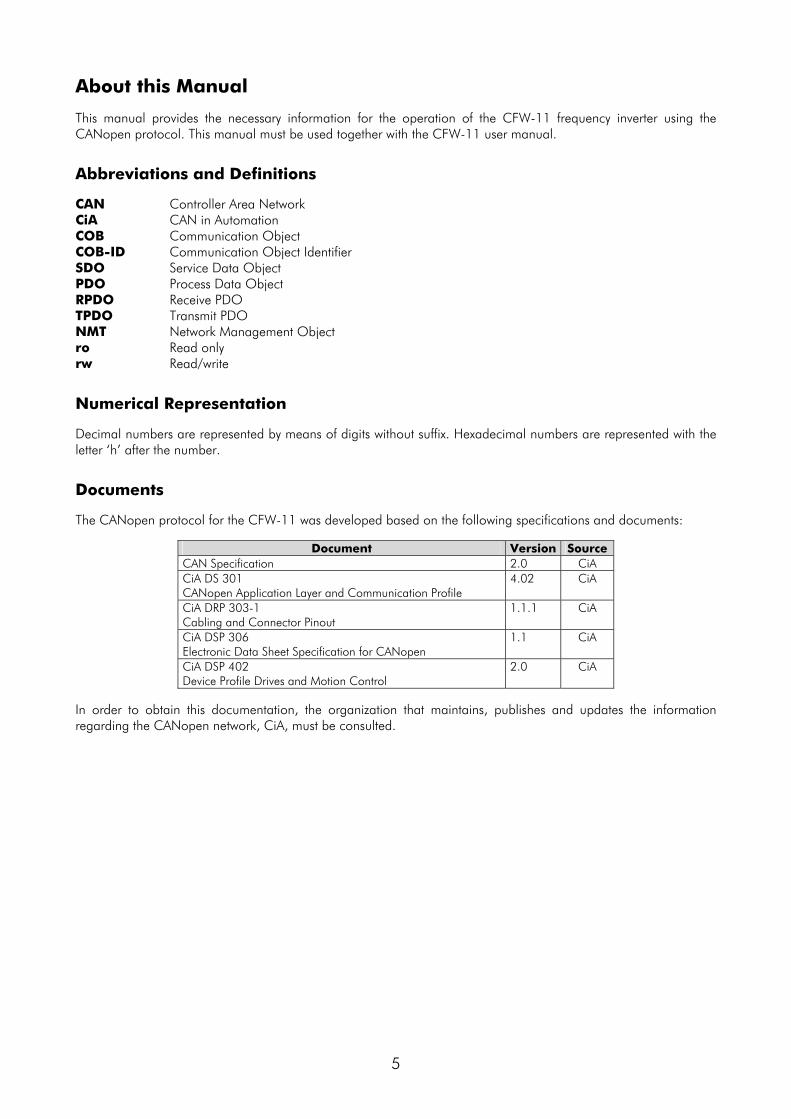
Documents The CANopen protocol for the CFW-11 was developed based on the following specifications and documents:
Document Version Source CAN Specification 2.0 CiA CiA DS 301 CANopen Application Layer and Communication Profile
4.02 CiA
CiA DRP 303-1 Cabling and Connector Pinout
1.1.1 CiA
CiA DSP 306 Electronic Data Sheet Specification for CANopen
1.1 CiA
CiA DSP 402 Device Profile Drives and Motion Control
2.0 CiA
In order to obtain this documentation, the organization that maintains, publishes and updates the information regarding the CANopen network, CiA, must be consulted.

1 Introduction to the CANopen Communication
In order to operate the CFW-11 frequency inverter in a CANopen network, it is necessary to know how the communication is performed. Therefore, this section brings a general description of the CANopen protocol operation, containing the functions used by the CFW-11. For a detailed description of the protocol, refer to the CANopen documentation indicated in the previous section.
1.1 CAN
CANopen is a network based on CAN, which means it uses CAN telegrams to exchange data in the network.
CAN is a serial communication protocol that describes the layer 2 services (data link layer)1 of the ISO/OSI model. In this layer are defined the different types of telegrams (frames), the error detection form, the validation and arbitration of messages.
1.1.1 Data Frame
In a CAN network data is transmitted by means of a data frame. This frame is composed mainly by an 11 bit2 identifier field (arbitration field), and a data field that may contain up to 8 data bytes.
Identifier 8 data bytes 11 bits byte 0 byte 1 byte 2 byte 3 byte 4 byte 5 byte 6 byte 7
1.1.2 Remote Frame
Besides the data frame, there is also the remote frame (RTR frame). This type of frame does not have data field, only identifier. It works as a request, so that another network device transmits the desired data frame.
1.1.3 Access to the Network
In a CAN network any element may try to transmit a telegram in a certain instant. If two elements try to access the network simultaneously, the one that sends the message with the highest priority will be able to transmit. The message priority is defined by the CAN frame identifier, the less the value of that identifier, the higher the message priority. The telegram with an identifier 0(zero) is the one with the highest priority.
1.1.4 Error Control
The CAN specification defines several error control mechanisms, which makes it a very reliable network and with a very low rate of undetected transmission errors. Each device in the network must be able to identify the occurrence of those errors and to inform the other elements that an error was detected.
A CAN network device has internal counters that are incremented every time a transmission or reception error is detected, and decremented when a telegram is sent or received with success. If a considerable amount of errors occurs, the device can be taken to the following conditions:
Warning: when this counter exceeds a certain limit, the device enters the warning state, meaning the occurrence of a high error rate.
Error Passive: when this value exceeds a higher limit, the device enters the error passive state, then it stops acting in the network when detecting that another device sent a telegram with error.
Bus Off: to conclude, there is the bus off state, in which the device will no longer send or receive telegrams.
1.1.5 CAN and CANopen
Only the definitions on how to detect errors and to create and transmit a frame, are not sufficient to define a meaning for the data that is sent through the network. There must be a specification that indicates how the identifier and the data must be assembled and how the information must be exchanged. In this way the elements of the
1 In the CAN protocol specification the ISO 11898 standard is referred as the definition of the layer 1 (physical layer) of this model. 2 The CAN 2.0 specification defines two types of data frames: standard (11 bits) and extended (29 bits). For the CFW-11 CANopen protocol, only standard frames are accepted.

network can interpret correctly the transmitted data. In this sense, the CANopen specification defines exactly how to exchange data among the equipments, and how each device must interpret these data.
There are several other protocols based on CAN, as DeviceNet, J1939, etc., which also use CAN frames for the communication. Those protocols however cannot co-operate in the same network.
1.2 CANopen Network Characteristics Because of using a CAN bus as telegram transmission means, all the CANopen network devices have the same right to access the network, where the identifier priority is responsible for solving conflict problems when simultaneous access occurs. This brings the benefit of making direct communication between slaves of the network possible, besides the fact that data can be made available in a more optimized manner without the need of a master that controls all the communication performing cyclic access to all the network devices for data updating. Another important characteristic is the use of the producer/consumer model for data transmission. This means that a message that transits in the network does not have a fixed network address as a destination. This message has an identifier that indicates what data it is transporting. Any element of the network that needs to use that information for its operation logic will be able to consume it, therefore, one message can be used by several network elements at the same time.
1.3 Physical Medium The physical medium for signal transmission in a CANopen network is specified by the ISO 11898 standard. It defines as transmission bus a pair of twisted wires with differential electrical signal. The CFW-11 frequency inverter uses an interface isolated from the network. The power supply for the CANopen interface is shared with the digital and analog inputs and outputs present on the CFW-11 control board. The component responsible for the transmission and reception of the signals is denominated transceiver, which complies with the specified by the ISO 11898.
1.4 Address in the CANopen Network Every CANopen network must have a master responsible for network management services, and it can also have a set of up to 127 slaves. Each network device can also be called node. Each slave is identified in a CANopen network by its address or Node-ID, which must be unique for each slave and may range from 1 to 127. The CFW-11 does not have functions for implementing the network management services; therefore, it must be used together with some equipment that has such services, generally a CANopen network master.
1.5 Access to the Data Each slave of the CANopen network has a list called object dictionary that contains all the data accessible via network. Each object of this list is identified with an index, which is used during the equipment configuration as well as during message exchanges. This index is used to identify the object being transmitted. A more detailed description on how the dictionary is structured is presented on section 6.
1.6 Data Transmission The transmission of numerical data via CANopen telegrams is done using a hexadecimal representation of the number, and sending the least significant data byte first. E.g.: The transmission of a 32 bit integer with sign (12345678h = 305419896 decimal), plus a 16 bit integer with sign (FF00h = -256 decimal), in a CAN frame.
Identifier 6 data bytes 32 bit integer 16 bit integer
byte 0 byte 1 byte 2 byte 3 byte 4 byte 5 11 bits 78h 56h 34h 12h 00h FFh

1.7 Communication Objects - COB
There is a specific set of objects that are responsible for the communication among the network devices. Those objects are divided according to the type of data and the way they are sent or received by a device. The CFW-11 supports the following communication objects (COB):
Table 1.1 - Types of Communication Objects (COB)
Type of object Description Service Data Object (SDO)
SDO are objects responsible for the direct access to the object dictionary of a device. By means of messages using SDO, it is possible to indicate explicitly (by the object index) what data is being handled. There are two SDO types: Client SDO, responsible for doing a read or write request to a network device, and the Server SDO, responsible for taking care of that request. Since SDO are usually used for the configuration of a network node, they have less priority than other types of message. Only a Server SDO is available for the CFW-11.
Process Data Object (PDO)
PDO are used for accessing equipment data without the need of indicating explicitly which dictionary object is being accessed. Therefore, it is necessary to configure previously which data the PDO will be transmitting (data mapping). There are also two types of PDO: Receive PDO and Transmit PDO. They are usually utilized for transmission and reception of data used in the device operation, and for that reason they have higher priority than the SDO.
Emergency Object (EMCY)
This object is responsible for sending messages to indicate the occurrence of errors in the device. When an error occurs in a specific device (EMCY producer), it can send a message to the network. In the case that any network device be monitoring that message (EMCY consumer), it can be programmed so that an action be taken (disabling the other devices, error reset, etc.). The CFW-11 has only the EMCY producer functionality.
Synchronization Object (SYNC)
In the CANopen network, it is possible to program a device (SYNC producer) to send periodically a synchronization message for all the network devices. Those devices (SYNC consumers) will then be able, for instance, to send a certain datum that needs to be made available periodically. The CFW-11 has the SYNC consumer function.
Network Management (NMT)
Every CANopen network needs a master that controls the other devices (slaves) in the network. This master will be responsible for a set of services that control the slave communications and their state in the CANopen network. The slaves are responsible for receiving the commands sent by the master and for executing the requested actions. The CFW-11 operates as a CANopen network slave and makes available two types of service that the master can use: device control service, with which the master controls the state of each network slave, and error control service (Node Guarding), with which the slave sends periodic messages to the master informing that the connection is active.
All the communication of the inverter with the network is performed using those objects, and the data that can be accessed are the existent in the device object dictionary. The working description of each COB is presented in section 7.
1.8 COB-ID
A telegram of the CANopen network is always transmitted by a communication object (COB). Every COB has an identifier that indicates the type of data that is being transported. This identifier, called COB-ID has an 11 bit size, and it is transmitted in the identifier field of a CAN telegram. It can be subdivided in two parts:
Function Code Node Address bit 10 bit 9 bit 8 bit 7 bit 6 bit 5 bit 4 bit 3 bit 2 bit 1 bit 0
Function Code: indicates the type of object that is being transmitted. Node Address: indicates with which network device the telegram is linked.
A table with the standard values for the different communication objects available in the CFW-11 is presented next. Notice that the standard value of the object depends on the slave address, with the exception of the COB-ID for NMT and SYNC, which are common for all the network elements. Those values can also be changed during the device configuration stage.
Table 1.2 - COB-ID for the different objects
COB Function code (bits 10 – 7)
Resultant COB-ID (function + address)
NMT 0000 0 SYNC 0001 128 (80h) EMCY 0001 129 – 255 (81h – FFh) PDO1 (tx) 0011 385 – 511 (181h – 1FFh) PDO1 (rx) 0100 513 – 639 (201h – 27Fh) PDO2 (tx) 0101 641 – 767 (281h – 2FFh) PDO2 (rx) 0110 769 – 895 (301h – 37Fh) PDO3 (tx) 0111 897 – 1023 (381h – 3FFh) PDO3 (rx) 1000 1025 – 1151 (401h – 47Fh) PDO4 (tx) 1001 1153 – 1279 (481h – 4FFh) PDO4 (rx) 1010 1281 – 1407 (501h – 57Fh) SDO (tx) 1011 1409 – 1535 (581h – 5FFh) SDO (rx) 1100 1537 – 1663 (601h – 67Fh) Node Guarding/Heartbeat 1110 1793 – 1919 (701h – 77Fh)

1.9 EDS File Each device in a CANopen network has an EDS configuration file that contains information about the operation of the device in the CANopen network, as well as the description of all the communication objects available. In general, this file is used by a master or by the configuration software for programming of devices present in the CANopen Network. The EDS configuration file for the CFW-11 is supplied together with the product, and it can also be obtained from the website http://www.weg.net. It is necessary to observe the inverter software version, in order to use an EDS file that be compatible with that version.
2 Optional Kits In order to make the CANopen communication possible with the CFW-11 frequency inverter, it is necessary to use one of the CAN communication kits described next. Information on the installation of the module in the inverter can be obtained in the guide that comes with the kit.
2.1 CAN Interfaces
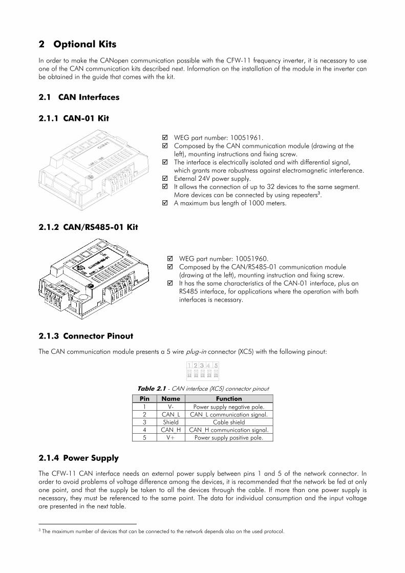
2.1.1 CAN-01 Kit
WEG part number: 10051961. Composed by the CAN communication module (drawing at the
left), mounting instructions and fixing screw. The interface is electrically isolated and with differential signal,
which grants more robustness against electromagnetic interference. External 24V power supply. It allows the connection of up to 32 devices to the same segment.
More devices can be connected by using repeaters3. A maximum bus length of 1000 meters.
2.1.2 CAN/RS485-01 Kit
WEG part number: 10051960. Composed by the CAN/RS485-01 communication module
(drawing at the left), mounting instruction and fixing screw. It has the same characteristics of the CAN-01 interface, plus an
RS485 interface, for applications where the operation with both interfaces is necessary.
2.1.3 Connector Pinout The CAN communication module presents a 5 wire plug-in connector (XC5) with the following pinout:
Table 2.1 - CAN interface (XC5) connector pinout
Pin Name Function 1 V- Power supply negative pole. 2 CAN_L CAN_L communication signal. 3 Shield Cable shield 4 CAN_H CAN_H communication signal. 5 V+ Power supply positive pole.
2.1.4 Power Supply The CFW-11 CAN interface needs an external power supply between pins 1 and 5 of the network connector. In order to avoid problems of voltage difference among the devices, it is recommended that the network be fed at only one point, and that the supply be taken to all the devices through the cable. If more than one power supply is necessary, they must be referenced to the same point. The data for individual consumption and the input voltage are presented in the next table. 3 The maximum number of devices that can be connected to the network depends also on the used protocol.
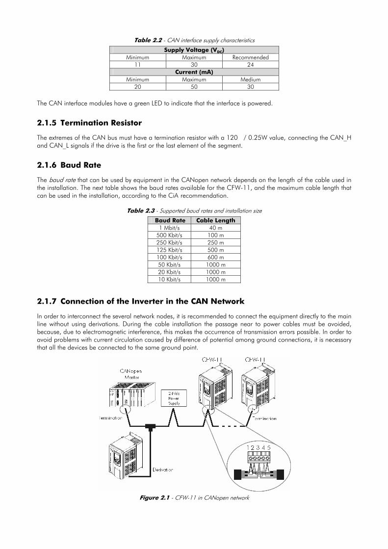
Table 2.2 - CAN interface supply characteristics
Supply Voltage (VDC) Minimum Maximum Recommended
11 30 24 Current (mA)
Minimum Maximum Medium 20 50 30
The CAN interface modules have a green LED to indicate that the interface is powered.
2.1.5 Termination Resistor The extremes of the CAN bus must have a termination resistor with a 120� / 0.25W value, connecting the CAN_H and CAN_L signals if the drive is the first or the last element of the segment.
2.1.6 Baud Rate The baud rate that can be used by equipment in the CANopen network depends on the length of the cable used in the installation. The next table shows the baud rates available for the CFW-11, and the maximum cable length that can be used in the installation, according to the CiA recommendation.
Table 2.3 - Supported baud rates and installation size
Baud Rate Cable Length 1 Mbit/s 40 m
500 Kbit/s 100 m 250 Kbit/s 250 m 125 Kbit/s 500 m 100 Kbit/s 600 m 50 Kbit/s 1000 m 20 Kbit/s 1000 m 10 Kbit/s 1000 m
2.1.7 Connection of the Inverter in the CAN Network In order to interconnect the several network nodes, it is recommended to connect the equipment directly to the main line without using derivations. During the cable installation the passage near to power cables must be avoided, because, due to electromagnetic interference, this makes the occurrence of transmission errors possible. In order to avoid problems with current circulation caused by difference of potential among ground connections, it is necessary that all the devices be connected to the same ground point.
Figure 2.1 - CFW-11 in CANopen network

The cable for the connection of the CAN_L and CAN_H signals must have a characteristic impedance of approximately 120 Ohm, and a maximum propagation delay of 5ns/m. Other characteristics depend on the cable length, which must be according to the next table.
Cable length (m) Resistance per meter
(mOhm/m) Conductor cross section
(mm2) 0 ... 40 70 0.25 ... 0.34
40 ... 300 <60 0.34 ... 0.60 300 ... 600 <40 0.50 ... 0.60 600 ... 1000 <26 0.75 ... 0.80
The maximum number of devices connected to a single segment of the network is limited to 64. Repeaters can be used for connecting a bigger number of devices.

3 Inverter Programming Next, only the CFW-11 frequency inverter parameters related to the CANopen communication will be presented.
3.1 Symbols for the Proprieties Description RO Read-only parameter. CFG Parameter that can be changed only with a stopped motor.
Net Parameter visible on the HMI if the inverter has the network interface installed – RS232, RS485, CAN, Anybus-CC, Profibus – or if the USB interface is connected.
Serial Parameter visible on the HMI if the inverter has the RS232 or RS485 interface installed. CAN Parameter visible on the HMI if the inverter has the CAN interface installed.
P0105 – 1st/2nd Ramp Selection
P0220 – Local/Remote Selection Source
P0221 – Speed Reference Selection – Local Situation
P0222 – Speed Reference Selection – Remote Situation
P0223 – Selection of the Rotation Direction - Local Situation
P0224 – Start/Stop Selection – Local Situation
P0225 – Jog Selection - Local Situation
P0226 – Selection of the Rotation Direction - Remote Situation
P0227 – Start/Stop Selection – Remote Situation
P0228 – Jog Selection - Remote Situation
These parameters are used in the configuration of the source of commands for the local and remote mode of the inverter CFW-11. So that the inverter is controlled through the CANopen interface, one of the available ‘CANopen/DNet’ in the parameters options must be selected. The detailed description of these parameters are found in the Programming the CFW-11 Manual.
P0313 – Communication Error Action
Range: 0 = Off Default: 0 1 = Ramp stop 2 = General disable 3 = Change to LOCAL 4 = Change to LOCAL keeping the commands and the reference 5 = Fault trip
Proprieties: CFG, Net
Access groups via HMI:
01 PARAMETER GROUPS. ∟ 49 Communication . ∟ 111 Status/Commands. Description: It allows the selection of the action to be executed by the inverter when a communication error is detected.

Table 3.1 - Values for parameter P0313
Options Description 0 = Off No action is taken and the inverter remains in the
existing status. 1 = Ramp Stop A stop command with deceleration ramp is executed
and the motor stops according to the programmed deceleration ramp.
2 = General Disable The inverter is disabled by removing the General Enabling and the motor coasts to stop.
3 = Change to LOCAL The inverter commands change to LOCAL. 4 = Change to LOCAL
keeping the commands and the reference
The inverter is changed to the local mode; However, the enabling and reference commands received via the network , in case the inverter had been programmed for start/stop via HMI or 3-wire and reference via HMI or electronic potentiometer, are kept in the local mode.
5 = Fault Trip Instead of an alarm, a communication error causes a fault at the inverter, so that it becomes necessary to perform the inverter fault reset in order to get it back to normal operation.
For the CAN interface being used with the CANopen protocol, the following events are considered communication errors:
A133 alarm/fault F233: CAN interface without power supply. A134 alarm/fault F234: bus off. A135 alarm/fault F235: CANopen communication error (Node Guarding)
The description of those alarms/faults is found in the section 7. The actions described in this parameter are executed by means of the automatic writing of the respective bits on the control via CAN parameter – P0684. In order to be effective, it is necessary that the inverter be programmed to be controlled via CAN interface. This programming is done by means of parameters P0220 to P0228.
P0680 – Logical Status
Range: 0000h – FFFFh Default: -
Proprieties: RO
Access groups via HMI:
01 PARAMETER GROUPS ∟ 49 Communication . ∟ 111 Status/Commands.
Description: It allows the monitoring of the inverter status. Each bit represents one state: Bits 15 14 13 12 11 10 9 8 7 6 5 4 to 0
Function
Faul
t con
ditio
n
Man
ual/
Aut
omat
ic
Und
ervo
ltage
LOC
/REM
JOG
Spee
d D
irect
ion
Gen
eral
Ena
blin
g ac
tive
Ram
p en
able
d
In A
larm
con
ditio
n
In c
onfig
urat
ion
mod
e
Seco
nd R
amp
Rese
rved
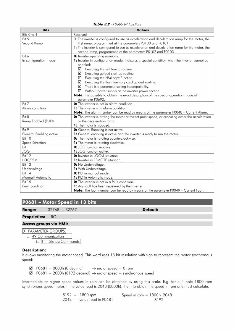
Table 3.2 - P0680 bit functions
Bits Values Bits 0 to 4 Reserved Bit 5 Second Ramp
0: The inverter is configured to use as acceleration and deceleration ramp for the motor, the first ramp, programmed at the parameters P0100 and P0101.
1: The inverter is configured to use as acceleration and deceleration ramp for the motor, the second ramp, programmed at the parameters P0102 and P0103.
Bit 6 In configuration mode
0: Inverter operating normally. 1: Inverter in configuration mode. Indicates a special condition when the inverter cannot be
enabled: Executing the self tuning routine. Executing guided start-up routine. Executing the HMI copy function. Executing the flash memory card guided routine. There is a parameter setting incompatibility. Without power supply at the inverter power section.
Note: It is possible to obtain the exact description of the special operation mode at parameter P0692.
Bit 7 Alarm condition
0: The inverter is not in alarm condition. 1: The inverter is in alarm condition. Note: The alarm number can be read by means of the parameter P0048 – Current Alarm.
Bit 8 Ramp Enabled (RUN)
0: The inverter is driving the motor at the set point speed, or executing either the acceleration or the deceleration ramp.
1: The motor is stopped. Bit 9 General Enabling active
0: General Enabling is not active. 1: General enabling is active and the inverter is ready to run the motor.
Bit 10 Speed Direction
0: The motor is rotating counterclockwise. 1: The motor is rotating clockwise.
Bit 11 JOG
0: JOG function inactive. 1: JOG function active.
Bit 12 LOC/REM
0: Inverter in LOCAL situation. 1: Inverter in REMOTE situation.
Bit 13 Undervoltage
0: No Undervoltage. 1: With Undervoltage.
Bit 14 Manual/ Automatic
0: PID in manual mode. 1: PID in Automatic mode.
Bit 15 Fault condition
0: The inverter is not in a fault condition. 1: Any fault has been registered by the inverter. Note: The fault number can be read by means of the parameter P0049 – Current Fault.
P0681 – Motor Speed in 13 bits
Range: -32768 … 32767 Default: -
Proprieties: RO
Access groups via HMI:
01 PARAMETER GROUPS. ∟ 49 Communication . ∟ 111 Status/Commands. Description: It allows monitoring the motor speed. This word uses 13 bit resolution with sign to represent the motor synchronous speed:
P0681 = 0000h (0 decimal) → motor speed = 0 rpm P0681 = 2000h (8192 decimal) → motor speed = synchronous speed
Intermediate or higher speed values in rpm can be obtained by using this scale. E.g. for a 4 pole 1800 rpm synchronous speed motor, if the value read is 2048 (0800h), then, to obtain the speed in rpm one must calculate:
8192 – 1800 rpm 2048 – value read in P0681
Speed in rpm = 1800 × 2048 8192

Speed in rpm = 450 rpm Negative values in this parameter indicate motor rotating in counterclockwise sense of rotation.
P0684 – CANopen/DeviceNet Control Word
Range: 0000h – FFFFh Default: 0000h
Proprieties: CAN
Access groups via HMI:
01 PARAMETER GROUPS. ∟ 49 Communication . ∟ 111 Status/Commands. Description: It is the inverter CANopen/DeviceNet Control word. This parameter can only be changed via the CAN interface (CANopen or DeviceNet protocols). For the other sources (HMI, USB, Serial, etc.) it behaves like a read-only parameter. In order that the commands written in this parameter be executed, it is necessary that the inverter be programmed to be commanded via CAN. This programming is done by means of parameters P0105 and P0220 to P0228. Each bit of this word represents a command that can be executed in the inverter. Bits 15 to 8 7 6 5 4 3 2 1 0
Function
Rese
rved
Faul
t res
et
Rese
rved
Seco
nd R
amp
Use
LOC
/REM
JOG
Spee
d D
irect
ion
Gen
eral
En
ablin
g
Star
t/St
op
Table 3.3 - P0684 Bit functions
Bits Values Bit 0 Start/Stop
0: It stops the motor with deceleration ramp. 1: The motor runs according to the acceleration ramp until reaching the speed reference
value. Bit 1 General Enabling
0: It disables the inverter, interrupting the supply for the motor. 1: It enables the inverter allowing the motor operation.
Bit 2 Speed Direction
0: To run the motor in a direction opposed to the speed reference. 1: To run the motor in the direction indicated by the speed reference.
Bit 3 JOG
0: It disables the JOG function. 1: It enables the JOG function.
Bit 4 LOC/REM
0: The inverter goes to the LOCAL situation. 1: The inverter goes to the REMOTE situation.
Bit 5 Second Ramp Use
0: The inverter uses as acceleration and deceleration ramp for the motor, the first ramp times, programmed at the parameters P0100 and P0101.
1: The inverter uses as acceleration and deceleration ramp for the motor, the second ramp times, programmed at the parameters P0102 and P0103.
Bits 6 Reserved Bit 7 Fault reset
0: No function. 1: If in a fault condition, then it executes the inverter reset.
Bits 8 to 15 Reserved
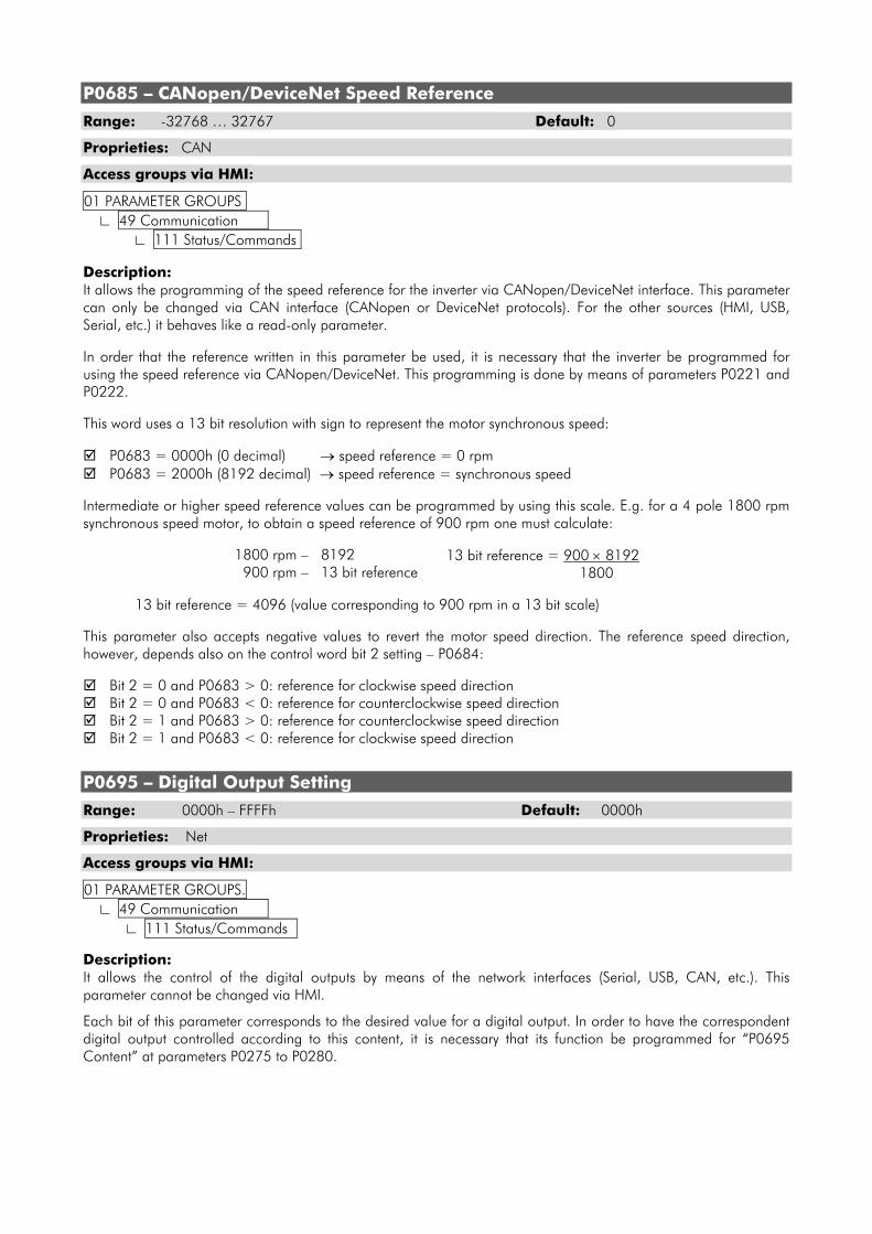
P0685 – CANopen/DeviceNet Speed Reference
Range: -32768 … 32767 Default: 0
Proprieties: CAN
Access groups via HMI:
01 PARAMETER GROUPS. ∟ 49 Communication . ∟ 111 Status/Commands. Description: It allows the programming of the speed reference for the inverter via CANopen/DeviceNet interface. This parameter can only be changed via CAN interface (CANopen or DeviceNet protocols). For the other sources (HMI, USB, Serial, etc.) it behaves like a read-only parameter. In order that the reference written in this parameter be used, it is necessary that the inverter be programmed for using the speed reference via CANopen/DeviceNet. This programming is done by means of parameters P0221 and P0222. This word uses a 13 bit resolution with sign to represent the motor synchronous speed:
P0683 = 0000h (0 decimal) → speed reference = 0 rpm P0683 = 2000h (8192 decimal) → speed reference = synchronous speed
Intermediate or higher speed reference values can be programmed by using this scale. E.g. for a 4 pole 1800 rpm synchronous speed motor, to obtain a speed reference of 900 rpm one must calculate:
1800 rpm – 8192 900 rpm – 13 bit reference
13 bit reference = 900 × 8192 1800
13 bit reference = 4096 (value corresponding to 900 rpm in a 13 bit scale) This parameter also accepts negative values to revert the motor speed direction. The reference speed direction, however, depends also on the control word bit 2 setting – P0684:
Bit 2 = 0 and P0683 > 0: reference for clockwise speed direction Bit 2 = 0 and P0683 < 0: reference for counterclockwise speed direction Bit 2 = 1 and P0683 > 0: reference for counterclockwise speed direction Bit 2 = 1 and P0683 < 0: reference for clockwise speed direction
P0695 – Digital Output Setting
Range: 0000h – FFFFh Default: 0000h
Proprieties: Net
Access groups via HMI:
01 PARAMETER GROUPS. ∟ 49 Communication . ∟ 111 Status/Commands.
Description: It allows the control of the digital outputs by means of the network interfaces (Serial, USB, CAN, etc.). This parameter cannot be changed via HMI.
Each bit of this parameter corresponds to the desired value for a digital output. In order to have the correspondent digital output controlled according to this content, it is necessary that its function be programmed for “P0695 Content” at parameters P0275 to P0280.
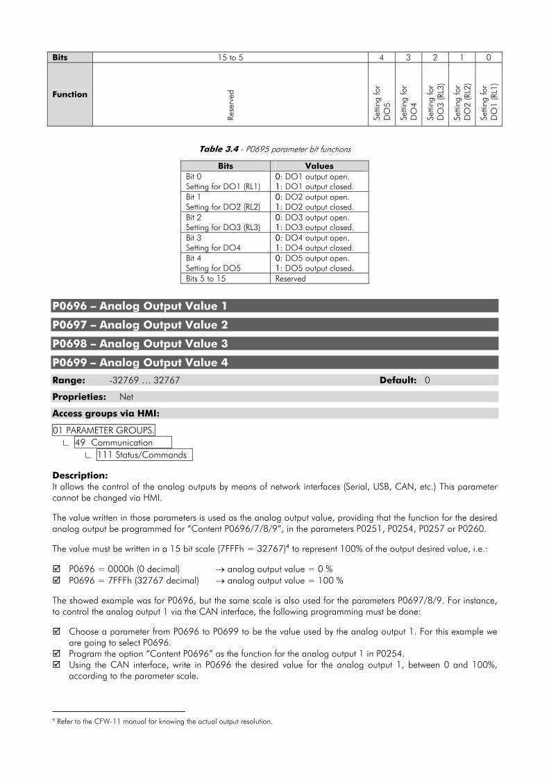
Bits 15 to 5 4 3 2 1 0
Function
Rese
rved
Setti
ng fo
r D
O5
Setti
ng fo
r D
O4
Setti
ng fo
r D
O3
(RL3
)
Setti
ng fo
r D
O2
(RL2
)
Setti
ng fo
r D
O1
(RL1
)
Table 3.4 - P0695 parameter bit functions
P0696 – Analog Output Value 1
P0697 – Analog Output Value 2
P0698 – Analog Output Value 3
P0699 – Analog Output Value 4
Range: -32769 … 32767 Default: 0
Proprieties: Net
Access groups via HMI:
01 PARAMETER GROUPS. ∟ 49 Communication . ∟ 111 Status/Commands. Description: It allows the control of the analog outputs by means of network interfaces (Serial, USB, CAN, etc.) This parameter cannot be changed via HMI. The value written in those parameters is used as the analog output value, providing that the function for the desired analog output be programmed for “Content P0696/7/8/9”, in the parameters P0251, P0254, P0257 or P0260. The value must be written in a 15 bit scale (7FFFh = 32767)4 to represent 100% of the output desired value, i.e.:
P0696 = 0000h (0 decimal) → analog output value = 0 % P0696 = 7FFFh (32767 decimal) → analog output value = 100 %
The showed example was for P0696, but the same scale is also used for the parameters P0697/8/9. For instance, to control the analog output 1 via the CAN interface, the following programming must be done:
Choose a parameter from P0696 to P0699 to be the value used by the analog output 1. For this example we are going to select P0696.
Program the option “Content P0696” as the function for the analog output 1 in P0254. Using the CAN interface, write in P0696 the desired value for the analog output 1, between 0 and 100%,
according to the parameter scale.
4 Refer to the CFW-11 manual for knowing the actual output resolution.
Bits Values Bit 0 Setting for DO1 (RL1)
0: DO1 output open. 1: DO1 output closed.
Bit 1 Setting for DO2 (RL2)
0: DO2 output open. 1: DO2 output closed.
Bit 2 Setting for DO3 (RL3)
0: DO3 output open. 1: DO3 output closed.
Bit 3 Setting for DO4
0: DO4 output open. 1: DO4 output closed.
Bit 4 Setting for DO5
0: DO5 output open. 1: DO5 output closed.
Bits 5 to 15 Reserved

NOTE! If the analog output is programmed for working from -10V to +10V, negative values must be programmed at the specific parameter, so that -32769 to 32767 represent a variation from -10V to +10V at the output.
P0700 – CAN Protocol
Range: 1 = CANopen Default: 2 2 = DeviceNet
Proprieties: CFG, CAN
Access groups via HMI:
01 PARAMETER GROUPS. ∟ 49 Communication . ∟ 112 CANopen/DeviceNet Description: It allows selecting the desired protocol for the CAN interface. In order to enable the CANopen protocol, it is necessary to program this parameter with the option ‘1 = CANopen’. If this parameter is changed, it becomes valid only after cycling power of the inverter.
P0701 – CAN Address
Range: 0 to 127 Default: 63
Proprieties: CFG, CAN
Access groups via HMI:
01 PARAMETER GROUPS. ∟ 49 Communication . ∟ 112 CANopen/DeviceNet Description: It allows programming the inverter address used for the CAN communication. It is necessary that each element of the network has an address different from the others. The valid addresses for this parameter depend on the protocol programmed in P0700:
P0700 = 1 (CANopen) → valid addresses: 1 to 127. P0700 = 2 (DeviceNet) → valid addresses: 0 to 63.
If this parameter is changed, it becomes valid only after cycling power of the inverter.
P0702 – CAN Baud Rate
Range: 0 = 1 Mbit/s Default: 0 1 = 800 Kbit/s 2 = 500 Kbit/s 3 = 250 Kbit/s 4 = 125 Kbit/s 5 = 100 Kbit/s 6 = 50 Kbit/s 7 = 20 Kbit/s 8 = 10 Kbit/s
Proprieties: CFG, CAN
Access groups via HMI:
01 PARAMETER GROUPS. ∟ 49 Communication . ∟ 112 CANopen/DeviceNet
Description: It allows programming the desired baud rate for the CAN interface, in bits per second. This rate must be the same for all the devices connected to the network.
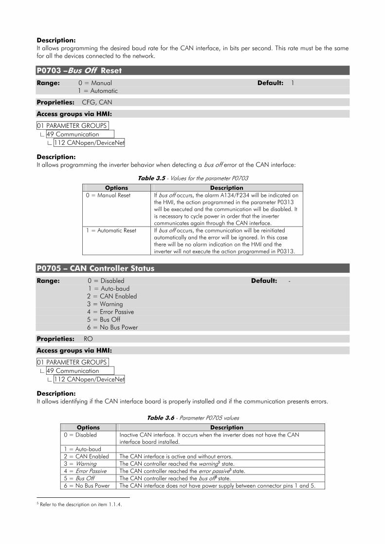
P0703 –Bus Off Reset
Range: 0 = Manual Default: 1 1 = Automatic
Proprieties: CFG, CAN
Access groups via HMI:
01 PARAMETER GROUPS. ∟ 49 Communication . ∟ 112 CANopen/DeviceNet Description: It allows programming the inverter behavior when detecting a bus off error at the CAN interface:
Table 3.5 - Values for the parameter P0703
Options Description 0 = Manual Reset If bus off occurs, the alarm A134/F234 will be indicated on
the HMI, the action programmed in the parameter P0313 will be executed and the communication will be disabled. It is necessary to cycle power in order that the inverter communicates again through the CAN interface.
1 = Automatic Reset If bus off occurs, the communication will be reinitiated automatically and the error will be ignored. In this case there will be no alarm indication on the HMI and the inverter will not execute the action programmed in P0313.
P0705 – CAN Controller Status
Range: 0 = Disabled Default: - 1 = Auto-baud 2 = CAN Enabled 3 = Warning 4 = Error Passive 5 = Bus Off 6 = No Bus Power
Proprieties: RO
Access groups via HMI:
01 PARAMETER GROUPS. ∟ 49 Communication . ∟ 112 CANopen/DeviceNet Description: It allows identifying if the CAN interface board is properly installed and if the communication presents errors.
Table 3.6 - Parameter P0705 values
Options Description 0 = Disabled Inactive CAN interface. It occurs when the inverter does not have the CAN
interface board installed. 1 = Auto-baud 2 = CAN Enabled The CAN interface is active and without errors. 3 = Warning The CAN controller reached the warning5 state. 4 = Error Passive The CAN controller reached the error passive5 state. 5 = Bus Off The CAN controller reached the bus off5 state. 6 = No Bus Power The CAN interface does not have power supply between connector pins 1 and 5.
5 Refer to the description on item 1.1.4.
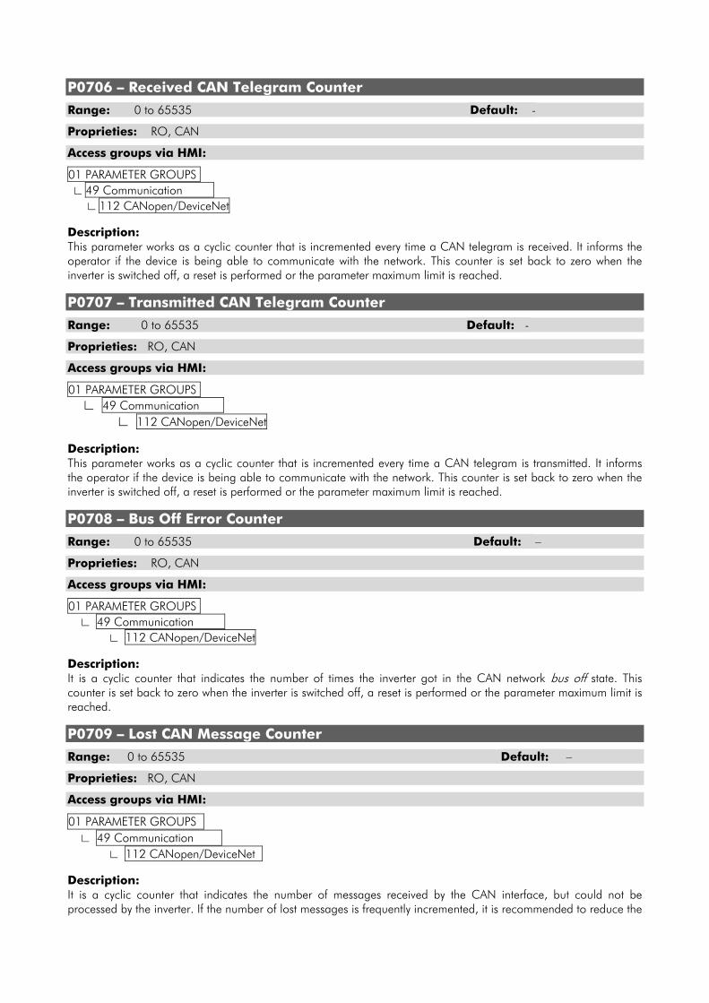
P0706 – Received CAN Telegram Counter
Range: 0 to 65535 Default: -
Proprieties: RO, CAN
Access groups via HMI:
01 PARAMETER GROUPS. ∟ 49 Communication . ∟ 112 CANopen/DeviceNet Description: This parameter works as a cyclic counter that is incremented every time a CAN telegram is received. It informs the operator if the device is being able to communicate with the network. This counter is set back to zero when the inverter is switched off, a reset is performed or the parameter maximum limit is reached.
P0707 – Transmitted CAN Telegram Counter
Range: 0 to 65535 Default: -
Proprieties: RO, CAN
Access groups via HMI:
01 PARAMETER GROUPS. ∟ 49 Communication . ∟ 112 CANopen/DeviceNet Description: This parameter works as a cyclic counter that is incremented every time a CAN telegram is transmitted. It informs the operator if the device is being able to communicate with the network. This counter is set back to zero when the inverter is switched off, a reset is performed or the parameter maximum limit is reached.
P0708 – Bus Off Error Counter
Range: 0 to 65535 Default: –
Proprieties: RO, CAN
Access groups via HMI:
01 PARAMETER GROUPS. ∟ 49 Communication . ∟ 112 CANopen/DeviceNet Description: It is a cyclic counter that indicates the number of times the inverter got in the CAN network bus off state. This counter is set back to zero when the inverter is switched off, a reset is performed or the parameter maximum limit is reached.
P0709 – Lost CAN Message Counter
Range: 0 to 65535 Default: –
Proprieties: RO, CAN
Access groups via HMI:
01 PARAMETER GROUPS. ∟ 49 Communication . ∟ 112 CANopen/DeviceNet . Description: It is a cyclic counter that indicates the number of messages received by the CAN interface, but could not be processed by the inverter. If the number of lost messages is frequently incremented, it is recommended to reduce the
used CAN network baud rate. This counter is set back to zero when the inverter is switched off, a reset is performed or the parameter maximum limit is reached.
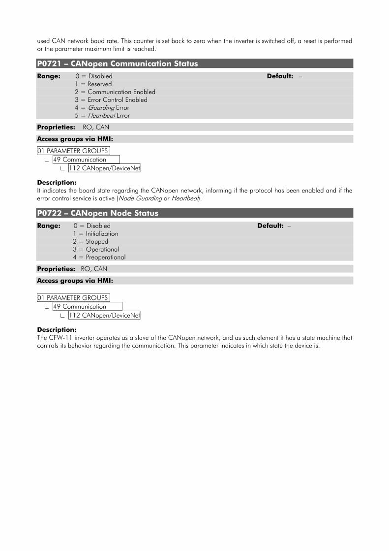
P0721 – CANopen Communication Status
Range: 0 = Disabled Default: – 1 = Reserved 2 = Communication Enabled 3 = Error Control Enabled 4 = Guarding Error 5 = Heartbeat Error
Proprieties: RO, CAN
Access groups via HMI:
01 PARAMETER GROUPS. ∟ 49 Communication . ∟ 112 CANopen/DeviceNet Description: It indicates the board state regarding the CANopen network, informing if the protocol has been enabled and if the error control service is active (Node Guarding or Heartbeat).
P0722 – CANopen Node Status
Range: 0 = Disabled Default: – 1 = Initialization 2 = Stopped 3 = Operational 4 = Preoperational
Proprieties: RO, CAN
Access groups via HMI: 01 PARAMETER GROUPS. ∟ 49 Communication . ∟ 112 CANopen/DeviceNet Description: The CFW-11 inverter operates as a slave of the CANopen network, and as such element it has a state machine that controls its behavior regarding the communication. This parameter indicates in which state the device is.
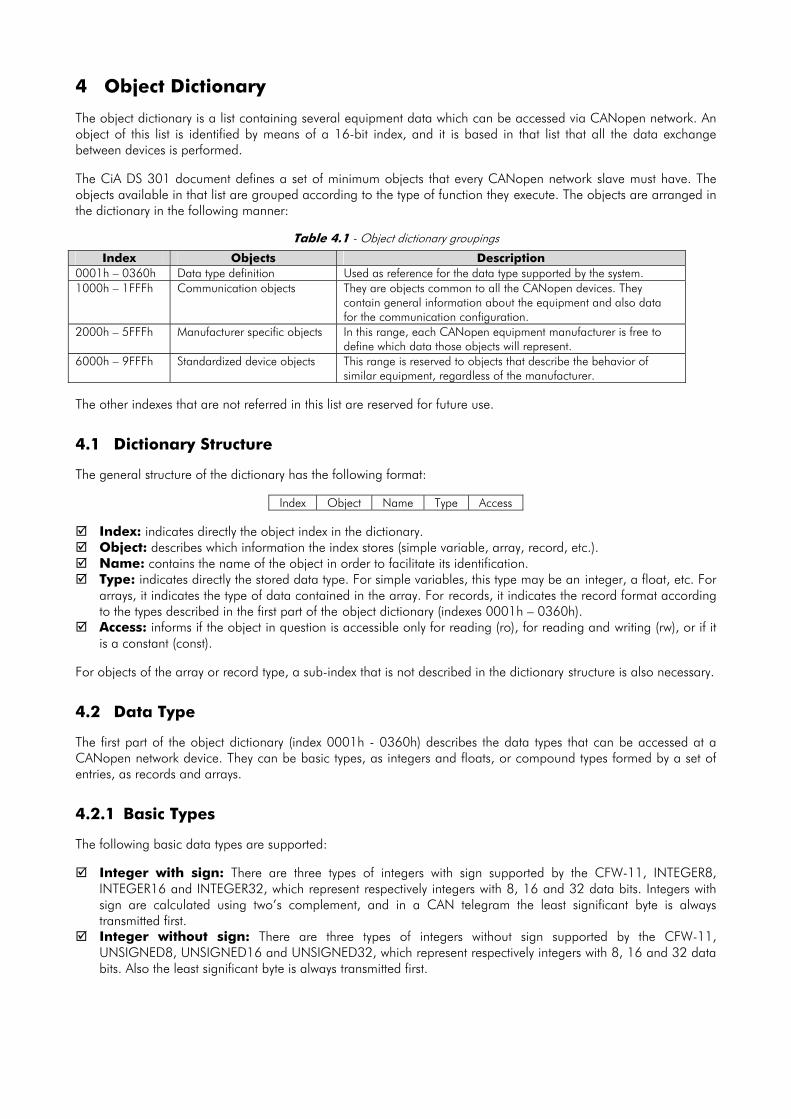
4 Object Dictionary The object dictionary is a list containing several equipment data which can be accessed via CANopen network. An object of this list is identified by means of a 16-bit index, and it is based in that list that all the data exchange between devices is performed. The CiA DS 301 document defines a set of minimum objects that every CANopen network slave must have. The objects available in that list are grouped according to the type of function they execute. The objects are arranged in the dictionary in the following manner:
Table 4.1 - Object dictionary groupings
Index Objects Description 0001h – 0360h Data type definition Used as reference for the data type supported by the system. 1000h – 1FFFh Communication objects
They are objects common to all the CANopen devices. They contain general information about the equipment and also data for the communication configuration.
2000h – 5FFFh Manufacturer specific objects In this range, each CANopen equipment manufacturer is free to define which data those objects will represent.
6000h – 9FFFh Standardized device objects This range is reserved to objects that describe the behavior of similar equipment, regardless of the manufacturer.
The other indexes that are not referred in this list are reserved for future use.
4.1 Dictionary Structure The general structure of the dictionary has the following format:
Index Object Name Type Access
Index: indicates directly the object index in the dictionary. Object: describes which information the index stores (simple variable, array, record, etc.). Name: contains the name of the object in order to facilitate its identification. Type: indicates directly the stored data type. For simple variables, this type may be an integer, a float, etc. For
arrays, it indicates the type of data contained in the array. For records, it indicates the record format according to the types described in the first part of the object dictionary (indexes 0001h – 0360h).
Access: informs if the object in question is accessible only for reading (ro), for reading and writing (rw), or if it is a constant (const).
For objects of the array or record type, a sub-index that is not described in the dictionary structure is also necessary.
4.2 Data Type The first part of the object dictionary (index 0001h - 0360h) describes the data types that can be accessed at a CANopen network device. They can be basic types, as integers and floats, or compound types formed by a set of entries, as records and arrays.
4.2.1 Basic Types The following basic data types are supported:
Integer with sign: There are three types of integers with sign supported by the CFW-11, INTEGER8, INTEGER16 and INTEGER32, which represent respectively integers with 8, 16 and 32 data bits. Integers with sign are calculated using two’s complement, and in a CAN telegram the least significant byte is always transmitted first.
Integer without sign: There are three types of integers without sign supported by the CFW-11, UNSIGNED8, UNSIGNED16 and UNSIGNED32, which represent respectively integers with 8, 16 and 32 data bits. Also the least significant byte is always transmitted first.
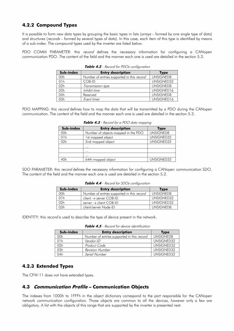
4.2.2 Compound Types It is possible to form new data types by grouping the basic types in lists (arrays – formed by one single type of data) and structures (records – formed by several types of data). In this case, each item of this type is identified by means of a sub-index. The compound types used by the inverter are listed below. PDO COMM PARAMETER: this record defines the necessary information for configuring a CANopen communication PDO. The content of the field and the manner each one is used are detailed in the section 5.3.
Table 4.2 - Record for PDOs configuration
Sub-index Entry description Type 00h Number of entries supported in this record UNSIGNED8 01h COB-ID UNSIGNED32 02h Transmission type UNSIGNED8 03h Inhibit time UNSIGNED16 04h Reserved UNSIGNED8 05h Event timer UNSIGNED16
PDO MAPPING: this record defines how to map the data that will be transmitted by a PDO during the CANopen communication. The content of the field and the manner each one is used are detailed in the section 5.3.
Table 4.3 - Record for a PDO data mapping
Sub-index Entry description Type 00h Number of objects mapped in the PDO UNSIGNED8 01h 1st mapped object UNSIGNED32 02h 2nd mapped object UNSIGNED32 ... ... ... 40h 64th mapped object UNSIGNED32
SDO PARAMETER: this record defines the necessary information for configuring a CANopen communication SDO. The content of the field and the manner each one is used are detailed in the section 5.2.
Table 4.4 - Record for SDOs configuration
Sub-index Entry description Type 00h Number of entries supported in this record UNSIGNED8 01h client → server COB-ID UNSIGNED32 02h server → client COB-ID UNSIGNED32 03h client/server Node-ID UNSIGNED8
IDENTITY: this record is used to describe the type of device present in the network.
Table 4.5 - Record for device identification
Sub-index Entry description Type 00h Number of entries supported in this record UNSIGNED8 01h Vendor-ID UNSIGNED32 02h Product Code UNSIGNED32 03h Revision Number UNSIGNED32 04h Serial Number UNSIGNED32
4.2.3 Extended Types The CFW-11 does not have extended types.
4.3 Communication Profile – Communication Objects The indexes from 1000h to 1FFFh in the object dictionary correspond to the part responsible for the CANopen network communication configuration. Those objects are common to all the devices, however only a few are obligatory. A list with the objects of this range that are supported by the inverter is presented next.
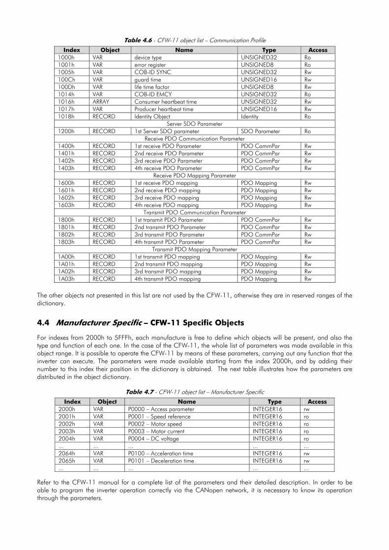
Table 4.6 - CFW-11 object list – Communication Profile
Index Object Name Type Access 1000h VAR device type UNSIGNED32 Ro 1001h VAR error register UNSIGNED8 Ro 1005h VAR COB-ID SYNC UNSIGNED32 Rw 100Ch VAR guard time UNSIGNED16 Rw 100Dh VAR life time factor UNSIGNED8 Rw 1014h VAR COB-ID EMCY UNSIGNED32 Ro 1016h ARRAY Consumer heartbeat time UNSIGNED32 Rw 1017h VAR Producer heartbeat time UNSIGNED16 Rw 1018h RECORD Identity Object Identity Ro
Server SDO Parameter 1200h RECORD 1st Server SDO parameter SDO Parameter Ro
Receive PDO Communication Parameter 1400h RECORD 1st receive PDO Parameter PDO CommPar Rw 1401h RECORD 2nd receive PDO Parameter PDO CommPar Rw 1402h RECORD 3rd receive PDO Parameter PDO CommPar Rw 1403h RECORD 4th receive PDO Parameter PDO CommPar Rw
Receive PDO Mapping Parameter 1600h RECORD 1st receive PDO mapping PDO Mapping Rw 1601h RECORD 2nd receive PDO mapping PDO Mapping Rw 1602h RECORD 3rd receive PDO mapping PDO Mapping Rw 1603h RECORD 4th receive PDO mapping PDO Mapping Rw
Transmit PDO Communication Parameter 1800h RECORD 1st transmit PDO Parameter PDO CommPar Rw 1801h RECORD 2nd transmit PDO Parameter PDO CommPar Rw 1802h RECORD 3rd transmit PDO Parameter PDO CommPar Rw 1803h RECORD 4th transmit PDO Parameter PDO CommPar Rw
Transmit PDO Mapping Parameter 1A00h RECORD 1st transmit PDO mapping PDO Mapping Rw 1A01h RECORD 2nd transmit PDO mapping PDO Mapping Rw 1A02h RECORD 3rd transmit PDO mapping PDO Mapping Rw 1A03h RECORD 4th transmit PDO mapping PDO Mapping Rw
The other objects not presented in this list are not used by the CFW-11, otherwise they are in reserved ranges of the dictionary.
4.4 Manufacturer Specific – CFW-11 Specific Objects For indexes from 2000h to 5FFFh, each manufacture is free to define which objects will be present, and also the type and function of each one. In the case of the CFW-11, the whole list of parameters was made available in this object range. It is possible to operate the CFW-11 by means of these parameters, carrying out any function that the inverter can execute. The parameters were made available starting from the index 2000h, and by adding their number to this index their position in the dictionary is obtained. The next table illustrates how the parameters are distributed in the object dictionary.
Table 4.7 - CFW-11 object list – Manufacturer Specific
Index Object Name Type Access 2000h VAR P0000 – Access parameter INTEGER16 rw 2001h VAR P0001 – Speed reference INTEGER16 ro 2002h VAR P0002 – Motor speed INTEGER16 ro 2003h VAR P0003 – Motor current INTEGER16 ro 2004h VAR P0004 – DC voltage INTEGER16 ro ... ... ... ... ... 2064h VAR P0100 – Acceleration time INTEGER16 rw 2065h VAR P0101 – Deceleration time INTEGER16 rw ... ... ... ... ...
Refer to the CFW-11 manual for a complete list of the parameters and their detailed description. In order to be able to program the inverter operation correctly via the CANopen network, it is necessary to know its operation through the parameters.

4.5 Device Profile – COMMON Objects for Drives The CANopen documentation also includes suggestions for standardization of certain device types. In the case of the CFW-11, it follows the CiA DPS 402 – Device Profile Drives and Motion Control description. This document describes a set of objects that must be common for drives, regardless of the manufacturer. This makes the interaction between devices with the same function easier (as for frequency inverters), because the data, as well as the device behavior, are made available in a standardized manner. For those objects the indexes from 6000h to 9FFFh were reserved. It is possible to operate the inverter through the CANopen network via the parameters (located from the index 2000h on), as well as by means of these standardized objects. Refer to the section 6 for a detailed description of which objects are available for this range of the object dictionary.
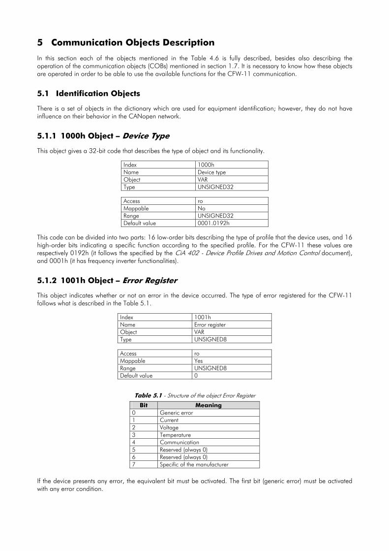
5 Communication Objects Description In this section each of the objects mentioned in the Table 4.6 is fully described, besides also describing the operation of the communication objects (COBs) mentioned in section 1.7. It is necessary to know how these objects are operated in order to be able to use the available functions for the CFW-11 communication.
5.1 Identification Objects There is a set of objects in the dictionary which are used for equipment identification; however, they do not have influence on their behavior in the CANopen network.
5.1.1 1000h Object – Device Type This object gives a 32-bit code that describes the type of object and its functionality.
Index 1000h Name Device type Object VAR Type UNSIGNED32
Access ro Mappable No Range UNSIGNED32 Default value 0001.0192h
This code can be divided into two parts: 16 low-order bits describing the type of profile that the device uses, and 16 high-order bits indicating a specific function according to the specified profile. For the CFW-11 these values are respectively 0192h (it follows the specified by the CiA 402 - Device Profile Drives and Motion Control document), and 0001h (it has frequency inverter functionalities).
5.1.2 1001h Object – Error Register This object indicates whether or not an error in the device occurred. The type of error registered for the CFW-11 follows what is described in the Table 5.1.
Index 1001h Name Error register Object VAR Type UNSIGNED8
Access ro Mappable Yes Range UNSIGNED8 Default value 0
Table 5.1 - Structure of the object Error Register
Bit Meaning 0 Generic error 1 Current 2 Voltage 3 Temperature 4 Communication 5 Reserved (always 0) 6 Reserved (always 0) 7 Specific of the manufacturer
If the device presents any error, the equivalent bit must be activated. The first bit (generic error) must be activated with any error condition.

5.1.3 1018h Object – Identity Object It brings general information about the device.
Index 1018h Name Identity object Object Record Type Identity
Sub-index 0 Description Number of the last sub-index Access ro Mappable No Range UNSIGNED8 Default value 4
Sub-index 1 Description Vendor ID Access ro Mappable No Range UNSIGNED32 Default value 0000.0123h
Sub-index 2 Description Product code Access ro Mappable No Range UNSIGNED32 Default value 0000.0400h
Sub-index 3 Description Revision number Access ro Mappable No Range UNSIGNED32 Default value According to the equipment firmware version
Sub-index 4 Description Serial number Access ro Mappable No Range UNSIGNED32 Default value Different for every CFW-11
The vendor ID is the number that identifies the manufacturer at the CiA. The product code is defined by the manufacturer according to the type of product. The revision number represents the equipment firmware version. The sub-index 4 is a unique serial number for each frequency inverter CFW-11 in CANopen network.
5.2 Service Data Objects – SDOS
The SDOs are responsible for the direct access to the object dictionary of a specific device in the network. They are used for the configuration and therefore have low priority, since they do not have to be used for communicating data necessary for the device operation.
There are two types of SDOs: client and server. Basically, the communication initiates with the client (usually the master of the network) making a read (upload) or write (download) request to a server, and then this server answers the request.

Figure 5.1 - Communication between SDO client and server
5.2.1 1200h Object – SDO Server The CFW-11 has only one SDO of the server type, which makes it possible the access to its entire object dictionary. Through it, an SDO client can configure the communication, the parameters and the inverter operation. Every SDO server has an object, of the SDO_PARAMETER type (refer to section 4.2.2), for its configuration, having the following structure:
Index 1200h Name SDO Server Parameter Object Record Type SDO Parameter
Sub-index 0 Description Number of the last sub-index Access ro Mappable No Range UNSIGNED8 Default value 2
Sub-index 1 Description COB-ID Client - Server (rx) Access ro Mappable No Range UNSIGNED32 Default value 600h + Node-ID
Sub-index 2 Description COB-ID Server - Client (tx) Access ro Mappable No Range UNSIGNED32 Default value 580h + Node-ID
5.2.2 SDOs Operation A telegram sent by an SDO has an 8 byte size, with the following structure:
Identifier 8 data bytes Command Index Sub-index Object data
11 bits byte 0 byte 1 byte 2 byte 3 byte 4 byte 5 byte 6 byte 7 The identifier depends on the transmission direction (rx or tx) and on the address (or Node-ID) of the destination server. For instance, a client that makes a request to a server which Node-ID is 1, must send a message with the identifier 601h. The server will receive this message and answer with a telegram which COB-ID is equal to 581h. The command code depends on the used function type. For the transmissions from a client to a server, the following commands can be used:

Table 5.2 - Command codes for SDO client
Command Function Description Object data 22h Download Write object Not defined 23h Download Write object 4 bytes 2Bh Download Write object 2 bytes 2Fh Download Write object 1 byte 40h Upload Read object Not used 60h or 70h Upload segment Segmented read Not used
When making a request, the client will indicate through its COB-ID, the address of the slave to which this request is destined. Only a slave (using its respective SDO server) will be able to answer the received telegram to the client. The answer telegram will have also the same structure of the request telegram, the commands however are different:
Table 5.3 - Command codes for SDO server
Command Function Description Object data 60h Download Response to write object Not used 43h Upload Response to read object 4 bytes 4Bh Upload Response to read object 2 bytes 4Fh Upload Response to read object 1 byte 41h Upload segment Initiates segmented response for read 4 bytes 01h ... 0Dh Upload segment Last data segment for read 8 ... 2 bytes
For readings of up to four data bytes, a single message can be transmitted by the server; for the reading of a bigger quantity of bytes, it is necessary that the client and the server exchange multiple telegrams. A telegram is only completed after the acknowledgement of the server to the request of the client. If any error is detected during telegram exchanges (for instance, no answer from the server), the client will be able to abort the process by means of a warning message with the command code equal to 80h.
NOTE! When the SDO is used for writing in objects that represent the CFW-11 parameters (objects starting from the index 2000h), this value is saved in the nonvolatile frequency inverter memory. Therefore, the configured values are not lost after the equipment is switched off or reset. For all the other objects these values are not saved automatically, so that it is necessary to rewrite the desired values.
E.g.: A client SDO requests for a CFW-11 at address 1 the reading of the object identified by the index 2000h, sub-index 0 (zero), which represents an 16-bit integer. The master telegram has the following format:
Identifier Command Index Sub-index Data 601h 40h 00h 20h 00h 00h 00h 00h 00h
The CFW-11 responds to the request indicating that the value of the referred object is equal to 9996:
Identifier Command Index Sub-index Data 581h 4Bh 00h 20h 00h E7 03h 00h 00h
5.3 Process Data Objects – PDOS The PDOs are used to send and receive data used during the device operation, which must often be transmitted in a fast and efficient manner. Therefore, they have a higher priority than the SDOs. In the PDOs only data are transmitted in the telegram (index and sub-index are omitted), and in this way it is possible to do a more efficient transmission, with larger volume of data in a single telegram. However it is necessary to configure previously what is being transmitted by the PDO, so that even without the indication of the index and sub-index, it is possible to know the content of the telegram. There are two types of PDOs, the receive PDO and the transmit PDO. The transmit PDOs are responsible for sending data to the network, whereas the receive PDOs remain responsible for receiving and handling these data.
6 Do not forget that for any integer type of data, the byte transfer order is from the least significant to the most significant.

In this way it is possible to have communication among slaves of the CANopen network, it is only necessary to configure one slave to transmit information and one or more slaves to receive this information.
Figure 5.2 - Communication using PDOs
NOTE! PDOs can only be transmitted or received when the device is in the operational state. The Figure 5.5 illustrates the available states for CANopen network node.
5.3.1 Mappable Objects for the PDOs In order to be able to be transmitted by a PDO, it is necessary that an object be mappable for this PDO content. In the description of communication objects (1000h – 1FFFh), the filed “Mappable” informs this possibility. Usually only information necessary for the operation of the device is mappable, such as enabling commands, device status, reference, etc. Information on the device configuration are not accessible through PDOs, and if it is necessary to access them one must use the SDOs. For CFW-11 specific objects (2000h – 5FFFh), the next table presents some objects mappable for the PDOs. Read-only parameters (ro) can be used only by transmit PDOs, whereas the other parameters can be used only by receive PDOs. The CFW-11 EDS file brings the list of all the objects available for the inverter, informing whether the object is mappable or not.
Table 5.4 - Examples of mappable parameters for PDOs
Index Object Name Type Access 2002h VAR P0002 – Motor speed UNSIGNED16 ro 2003h VAR P0003 – Motor current UNSIGNED16 ro 2004h VAR P0004 – DC link voltage (Ud) UNSIGNED16 ro 2005h VAR P0005 – Motor frequency UNSIGNED16 ro 2006h VAR P0006 – Inverter status UNSIGNED16 ro 2007h VAR P0007 – Output voltage UNSIGNED16 ro 2009h VAR P0009 – Motor torque INTEGER16 ro 200Ah VAR P0010 – Output power UNSIGNED16 ro 200Ch VAR P0012 – DI1 to DI8 status UNSIGNED16 ro 200Dh VAR P0013 – DO1 to RL3 status UNSIGNED16 ro 2012h VAR P0018 – AI1 value INTEGER16 ro 2013h VAR P0019 – AI2 value INTEGER16 ro 2014h VAR P0020 – AI3 value INTEGER16 ro 2015h VAR P0021 – AI4 value INTEGER16 ro 2064h VAR P0100 – Acceleration time UNSIGNED16 rw 2065h VAR P0101 – Deceleration time UNSIGNED16 rw 22A8h VAR P0680 – Logical status UNSIGNED16 ro 22A9h VAR P0681 – Motor speed in 13 bits UNSIGNED16 ro 22ACh VAR P0684 – Control CANopen/DeviceNet UNSIGNED16 rw 22ADh VAR P0685 – Speed reference CANopen/DeviceNet UNSIGNED16 rw

5.3.2 Receive PDOs The receive PDOs, or RPDOs, are responsible for receiving data that other devices send to the CANopen network. The CFW-11 has 4 receive PDOs, each one being able to receive up to 8 bytes. Each RPDO has two parameters for its configuration, a PDO_COMM_PARAMETER and a PDO_MAPPING, as described next. PDO_COMM_PARAMETER
Index 1400h Name Receive PDO communication parameter Object Record Type PDO COMM PARAMETER
Sub-index 0 Description Number of the last sub-index Access ro Mappable No Range UNSIGNED8 Default value 2
Sub-index 1 Description COB-ID used by the PDO Access rw Mappable No Range UNSIGNED32 Default value 1400h: 200h + Node-ID
1401h: 300h + Node-ID 1402h: 400h + Node-ID 1403h: 500h + Node-ID
Sub-index 2 Description Type of transmission Access rw Mappable No Range UNSIGNED8 Default value 254
The sub-index 1 contains the receive PDO COB-ID. Every time a message is sent to the network, this object will read the COB-ID of that message and, if it is equal to the value of this field, the message will be received by the device. This field is formed by an UNSIGNED32 with the following structure:
Table 5.5 - COB-ID description
Bit Value Description 0 PDO is enabled 31 (MSB) 1 PDO is disabled
30 0 RTR permitted 29 0 Identifier size = 11 bits 28 – 11 0 Not used, always 0 10 – 0 (LSB) X 11-bit COB-ID
The bit 31 allows enabling or disabling the PDO. The bits 29 and 30 must be kept in 0 (zero), they indicate respectively that the PDO accepts remote frames (RTR frames) and that it uses an 11-bit identifier. Since the CFW-11 frequency inverter does not use 29-bit identifiers, the bits from 28 to 11 must be kept in 0 (zero), whereas the bits from 10 to 0 (zero) are used to configure the COB-ID for the PDO. The sub-index 2 indicates the transmission type of this object, according to the next table.

Table 5.6 - Description of the type of transmission
Type of transmission PDOs transmission Cyclic Acyclic Synchronous Asynchronous RTR 0 • • 1 – 240 • • 241 – 251 Reserved 252 • • 253 • • 254 • 255 •
Values 0 – 240: any RPDO programmed in this range presents the same performance. When detecting a message, it will receive the data; however it won't update the received values until detecting the next SYNC telegram.
Values 252 and 253: not allowed for receive PDOs. Values 254 and 255: they indicated that there is no relationship with the synchronization object. When
receiving a message, its values are updated immediately.
PDO_MAPPING
Index 1600h
Name Receive PDO mapping
Object Record
Type PDO MAPPING
Sub-index 0 Description Number of mapped objects Access ro Mappable No Range 0 = disabled
1 ... 4 = number of mapped objects Default value 1600h: 1
1601h: 2 1602h: 2 1603h: 2
Sub-index 1 Description 1st object mapped in the PDO Access rw Mappable No Range UNSIGNED32 Default value 1600h: 6040.0010h
1601h: 6040.0010h 1602h: 6040.0010h 1603h: 22AC.0010h
Sub-index 2 Description 2nd object mapped in the PDO Access rw Mappable No Range UNSIGNED32 Default value 1600h: 0
1601h: 6060.0008h 1602h: 6042.0010h 1603h: 22AD.0010h
Sub-index 3 Description 3rd object mapped in the PDO Access rw Mappable No Range UNSIGNED32 Default value 1600h: 0
1601h: 0 1602h: 0 1603h: 0
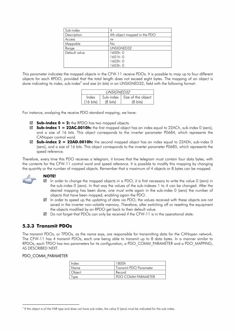
Sub-index 4 Description 4th object mapped in the PDO Access rw Mappable No Range UNSIGNED32 Default value 1600h: 0
1601h: 0 1602h: 0 1603h: 0
This parameter indicates the mapped objects in the CFW-11 receive PDOs. It is possible to map up to four different objects for each RPDO, provided that the total length does not exceed eight bytes. The mapping of an object is done indicating its index, sub-index7 and size (in bits) in an UNSIGNED32, field with the following format:
UNSIGNED32 Index
(16 bits) Sub-index
(8 bits) Size of the object
(8 bits) For instance, analyzing the receive PDO standard mapping, we have:
Sub-index 0 = 2: the RPDO has two mapped objects. Sub-index 1 = 22AC.0010h: the first mapped object has an index equal to 22ACh, sub-index 0 (zero),
and a size of 16 bits. This object corresponds to the inverter parameter P0684, which represents the CANopen control word.
Sub-index 2 = 22AD.0010h: the second mapped object has an index equal to 22ADh, sub-index 0 (zero), and a size of 16 bits. This object corresponds to the inverter parameter P0685, which represents the speed reference.
Therefore, every time this PDO receives a telegram, it knows that the telegram must contain four data bytes, with the contents for the CFW-11 control word and speed reference. It is possible to modify this mapping by changing the quantity or the number of mapped objects. Remember that a maximum of 4 objects or 8 bytes can be mapped.
NOTE!
In order to change the mapped objects in a PDO, it is first necessary to write the value 0 (zero) in the sub-index 0 (zero). In that way the values of the sub-indexes 1 to 4 can be changed. After the desired mapping has been done, one must write again in the sub-index 0 (zero) the number of objects that have been mapped, enabling again the PDO.
In order to speed up the updating of data via PDO, the values received with these objects are not saved in the inverter non-volatile memory. Therefore, after switching off or resetting the equipment the objects modified by an RPDO get back to their default value.
Do not forget that PDOs can only be received if the CFW-11 is in the operational state.
5.3.3 Transmit PDOs
The transmit PDOs, or TPDOs, as the name says, are responsible for transmitting data for the CANopen network. The CFW-11 has 4 transmit PDOs, each one being able to transmit up to 8 data bytes. In a manner similar to RPDOs, each TPDO has two parameters for its configuration, a PDO_COMM_PARAMETER and a PDO_MAPPING, AS DESCRIBED NEXT.
PDO_COMM_PARAMETER
Index 1800h Name Transmit PDO Parameter Object Record Type PDO COMM PARAMETER
7 If the object is of the VAR type and does not have sub-index, the value 0 (zero) must be indicated for the sub-index.
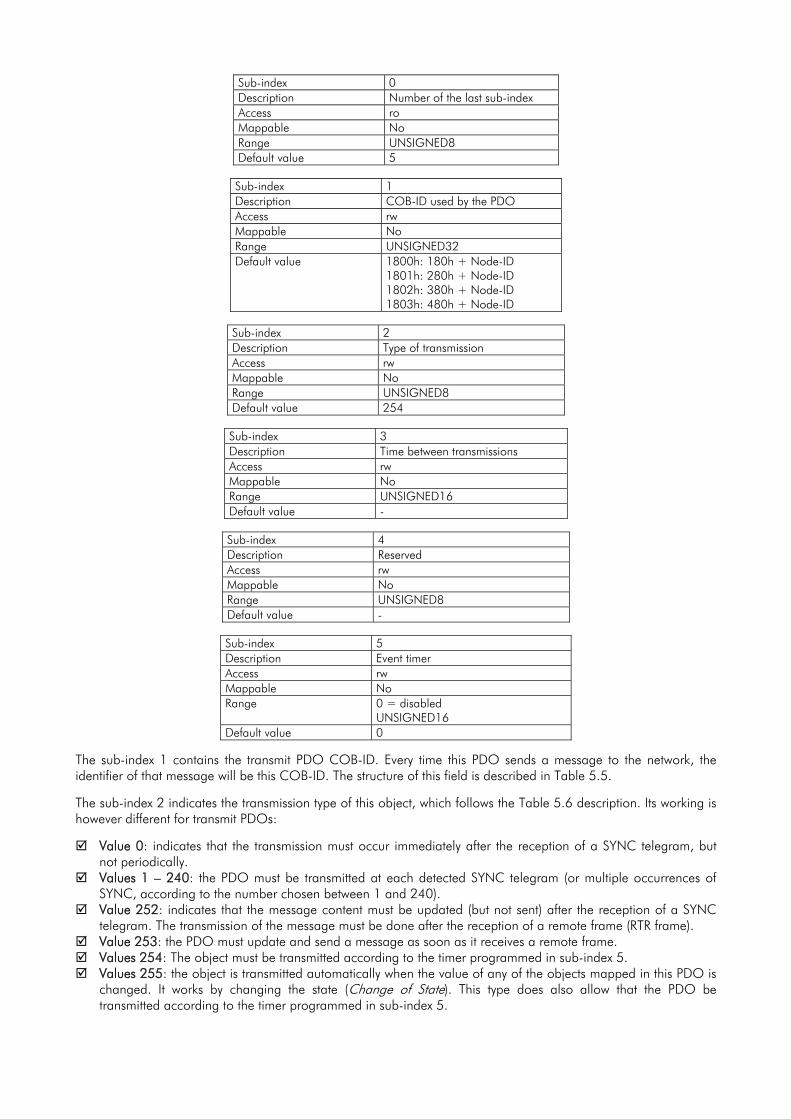
Sub-index 0 Description Number of the last sub-index Access ro Mappable No Range UNSIGNED8 Default value 5
Sub-index 1 Description COB-ID used by the PDO Access rw Mappable No Range UNSIGNED32 Default value 1800h: 180h + Node-ID
1801h: 280h + Node-ID 1802h: 380h + Node-ID 1803h: 480h + Node-ID
Sub-index 2 Description Type of transmission Access rw Mappable No Range UNSIGNED8 Default value 254
Sub-index 3 Description Time between transmissions Access rw Mappable No Range UNSIGNED16 Default value -
Sub-index 4 Description Reserved Access rw Mappable No Range UNSIGNED8 Default value -
Sub-index 5 Description Event timer Access rw Mappable No Range 0 = disabled
UNSIGNED16 Default value 0
The sub-index 1 contains the transmit PDO COB-ID. Every time this PDO sends a message to the network, the identifier of that message will be this COB-ID. The structure of this field is described in Table 5.5.
The sub-index 2 indicates the transmission type of this object, which follows the Table 5.6 description. Its working is however different for transmit PDOs:
Value 0: indicates that the transmission must occur immediately after the reception of a SYNC telegram, but not periodically.
Values 1 – 240: the PDO must be transmitted at each detected SYNC telegram (or multiple occurrences of SYNC, according to the number chosen between 1 and 240).
Value 252: indicates that the message content must be updated (but not sent) after the reception of a SYNC telegram. The transmission of the message must be done after the reception of a remote frame (RTR frame).
Value 253: the PDO must update and send a message as soon as it receives a remote frame. Values 254: The object must be transmitted according to the timer programmed in sub-index 5. Values 255: the object is transmitted automatically when the value of any of the objects mapped in this PDO is
changed. It works by changing the state (Change of State). This type does also allow that the PDO be transmitted according to the timer programmed in sub-index 5.
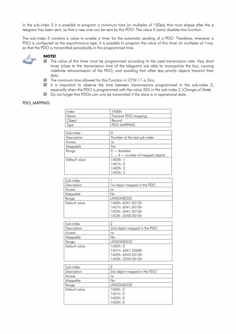
In the sub-index 3 it is possible to program a minimum time (in multiples of 100μs) that must elapse after the a telegram has been sent, so that a new one can be sent by this PDO. The value 0 (zero) disables this function. The sub-index 5 contains a value to enable a timer for the automatic sending of a PDO. Therefore, whenever a PDO is configured as the asynchronous type, it is possible to program the value of this timer (in multiples of 1ms), so that the PDO is transmitted periodically in the programmed time.
NOTE!
The value of this timer must be programmed according to the used transmission rate. Very short times (close to the transmission time of the telegram) are able to monopolize the bus, causing indefinite retransmission of the PDO, and avoiding that other less priority objects transmit their data.
The minimum time allowed for this Function in CFW-11 is 2ms. It is important to observe the time between transmissions programmed in the sub-index 3,
especially when the PDO is programmed with the value 255 in the sub-index 2 (Change of State). Do not forget that PDOs can only be transmitted if the slave is in operational state.
PDO_MAPPING
Index 1A00h Name Transmit PDO mapping Object Record Type PDO MAPPING
Sub-index 0 Description Number of the last sub-index Access ro Mappable No Range 0 = disabled
1 ... 4 = number of mapped objects Default value 1A00h: 1
1A01h: 2 1A02h: 2 1A03h: 2
Sub-index 1 Description 1st object mapped in the PDO Access rw Mappable No Range UNSIGNED32 Default value 1A00h: 6041.0010h
1A01h: 6041.0010h 1A02h: 6041.0010h 1A03h: 22A8.0010h
Sub-index 2 Description 2nd object mapped in the PDO Access rw Mappable No Range UNSIGNED32 Default value 1A00h: 0
1A01h: 6061.0008h 1A02h: 6044.0010h 1A03h: 22A9.0010h
Sub-index 3 Description 3rd object mapped in the PDO Access rw Mappable No Range UNSIGNED32 Default value 1A00h: 0
1A01h: 0 1A02h: 0 1A03h: 0
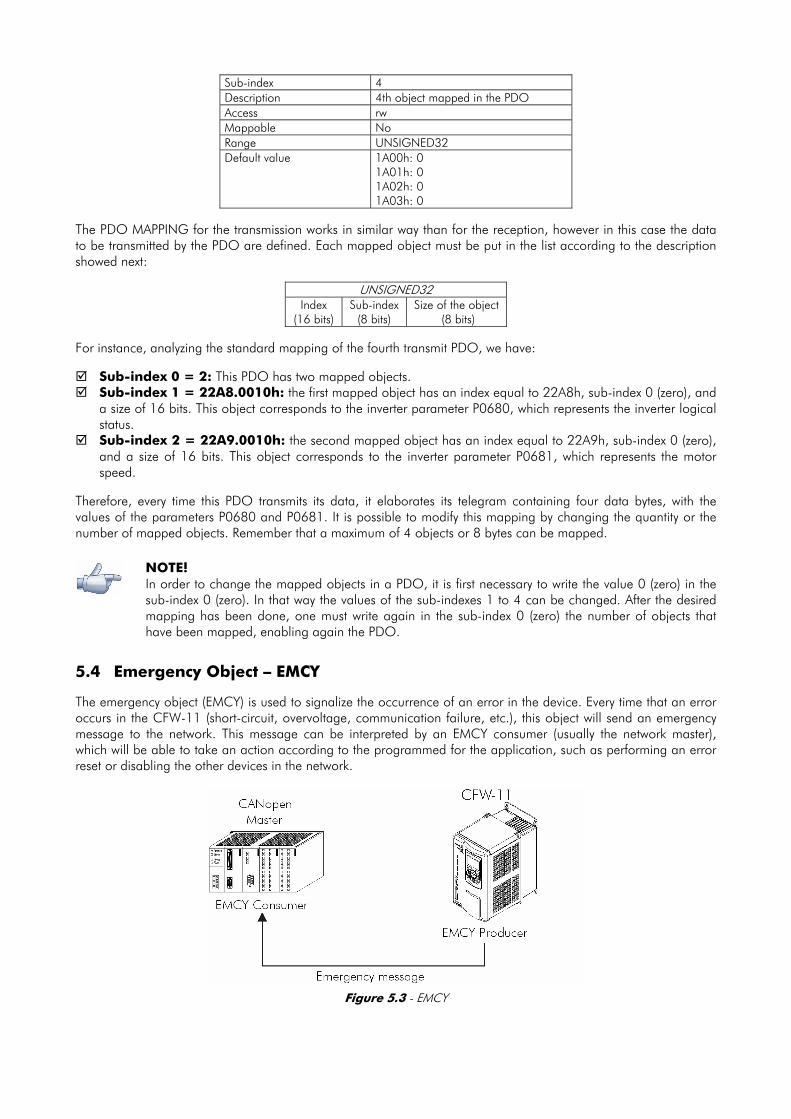
Sub-index 4 Description 4th object mapped in the PDO Access rw Mappable No Range UNSIGNED32 Default value 1A00h: 0
1A01h: 0 1A02h: 0 1A03h: 0
The PDO MAPPING for the transmission works in similar way than for the reception, however in this case the data to be transmitted by the PDO are defined. Each mapped object must be put in the list according to the description showed next:
UNSIGNED32 Index
(16 bits) Sub-index
(8 bits) Size of the object
(8 bits) For instance, analyzing the standard mapping of the fourth transmit PDO, we have:
Sub-index 0 = 2: This PDO has two mapped objects. Sub-index 1 = 22A8.0010h: the first mapped object has an index equal to 22A8h, sub-index 0 (zero), and
a size of 16 bits. This object corresponds to the inverter parameter P0680, which represents the inverter logical status.
Sub-index 2 = 22A9.0010h: the second mapped object has an index equal to 22A9h, sub-index 0 (zero), and a size of 16 bits. This object corresponds to the inverter parameter P0681, which represents the motor speed.
Therefore, every time this PDO transmits its data, it elaborates its telegram containing four data bytes, with the values of the parameters P0680 and P0681. It is possible to modify this mapping by changing the quantity or the number of mapped objects. Remember that a maximum of 4 objects or 8 bytes can be mapped.
NOTE! In order to change the mapped objects in a PDO, it is first necessary to write the value 0 (zero) in the sub-index 0 (zero). In that way the values of the sub-indexes 1 to 4 can be changed. After the desired mapping has been done, one must write again in the sub-index 0 (zero) the number of objects that have been mapped, enabling again the PDO.
5.4 Emergency Object – EMCY The emergency object (EMCY) is used to signalize the occurrence of an error in the device. Every time that an error occurs in the CFW-11 (short-circuit, overvoltage, communication failure, etc.), this object will send an emergency message to the network. This message can be interpreted by an EMCY consumer (usually the network master), which will be able to take an action according to the programmed for the application, such as performing an error reset or disabling the other devices in the network.
Figure 5.3 - EMCY
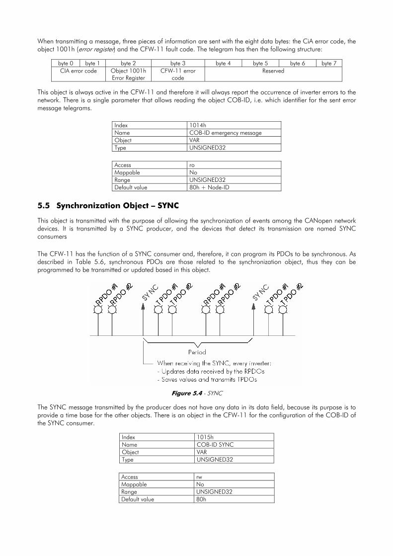
When transmitting a message, three pieces of information are sent with the eight data bytes: the CiA error code, the object 1001h (error register) and the CFW-11 fault code. The telegram has then the following structure:
byte 0 byte 1 byte 2 byte 3 byte 4 byte 5 byte 6 byte 7 CIA error code Object 1001h
Error Register CFW-11 error
code Reserved
This object is always active in the CFW-11 and therefore it will always report the occurrence of inverter errors to the network. There is a single parameter that allows reading the object COB-ID, i.e. which identifier for the sent error message telegrams.
Access ro Mappable No Range UNSIGNED32 Default value 80h + Node-ID
5.5 Synchronization Object – SYNC This object is transmitted with the purpose of allowing the synchronization of events among the CANopen network devices. It is transmitted by a SYNC producer, and the devices that detect its transmission are named SYNC consumers The CFW-11 has the function of a SYNC consumer and, therefore, it can program its PDOs to be synchronous. As described in Table 5.6, synchronous PDOs are those related to the synchronization object, thus they can be programmed to be transmitted or updated based in this object.
Figure 5.4 - SYNC The SYNC message transmitted by the producer does not have any data in its data field, because its purpose is to provide a time base for the other objects. There is an object in the CFW-11 for the configuration of the COB-ID of the SYNC consumer.
Index 1015h Name COB-ID SYNC Object VAR Type UNSIGNED32
Access rw Mappable No Range UNSIGNED32 Default value 80h
Index 1014h Name COB-ID emergency message Object VAR Type UNSIGNED32

NOTE! The period of the SYNC telegrams must be programmed in the producer according to the transmission rate and the number of synchronous PDOs to be transmitted. There must be enough time for the transmission of these objects, and it is also recommended that there is a tolerance to make it possible the transmission of asynchronous messages, such as EMCY, asynchronous PDOs and SDOs.
5.6 Network Management – NMT The network management object is responsible for a series of services that control the communication of the device in a CANopen network. For the CFW-11 the services of node control and error control are available (using Node Guarding or Heartbeat).
5.6.1 Slave State Control With respect to the communication, a CANopen network device can be described by the following state machine:
Figure 5.5 - CANopen node state diagram
Table 5.7 - Transitions Description
Transition Description 1 The device is switched on and initiates the initialization (automatic). 2 Initialization concluded, it goes to the preoperational state (automatic). 3 It receives the Start Node command for entering the operational state. 4 It receives the Enter Pre-Operational command, and goes to the preoperational state. 5 It receives the Stop Node command for entering the stopped state. 6 It receives the Reset Node command, when it executes the device complete reset. 7 It receives the Reset Communication command, when it reinitializes the object values and the CANopen device
communication.
During the initialization the Node-ID is defined, the objects are created and the interface with the CAN network is configured. Communication with the device is not possible during this stage, which is concluded automatically. At the end of this stage the slave sends to the network a telegram of the Boot-up Object, used only to indicate that the initialization has been concluded and that the slave has entered the preoperational state. This telegram has the identifier 700h + Node-ID, and only one data byte with value equal to 0 (zero). In the preoperational state it is already possible to communicate with the slave, but its PDOs are not yet available for operation. In the operational state all the objects are available, whereas in the stopped state only the NMT object can receive or transmit telegrams to the network. The next table shows the objects available for each state.

Table 5.8 - Objects accessible in each state
Initialization Preoperational Operational Stopped PDO • SDO • • SYNC • • EMCY • • Boot-up • NMT • • •
This state machine is controlled by the network master, which sends to each slave the commands so that the desired state change be executed. These telegrams do not have confirmation, what means that the slave does only receive the telegram without returning an answer to the master. The received telegrams have the following structure:
Identifier byte 1 byte 2 00h Command code Destination Node-ID
Table 5.9 - Commands for the state transition
Command code Destination Node-ID 1 = START node (transition 3) 2 = STOP node (transition 4) 128 = Enter pre-operational (transition 5) 129 = Reset node (transition 6) 130 = Reset communication (transition 7)
0 = All the slaves 1 ... 127 = Specific slave
The transitions indicated in the command code correspond to the state transitions executed by the node after receiving the command (according to the Figure 5.5). The Reset node command makes the CFW-11 execute a complete reset of the device, while the Reset communication command causes the device to reinitialize only the objects pertinent to the CANopen communication.
5.6.2 Error Control – Node Guarding This service is used to make it possible the monitoring of the communication with the CANopen network, both by the master and the slave as well. In this type of service the master sends periodical telegrams to the slave, which responds to the received telegram. If some error that interrupts the communication occurs, it will be possible to identify this error, because the master as well as the slave will be notified by the Timeout in the execution of this service. The error events are called Node Guarding for the master and Life Guarding for the slave.
Figure 5.6 - Error control service – Node Guarding There are two objects of the dictionary for the configuration of the error detection times for the Node Guarding service:

Index 100Ch Name Guard Time Object VAR Type UNSIGNED16
Access rw Mappable No Range UNSIGNED16 Default value 0
Index 100Dh Name Life Time Factor Object VAR Type UNSIGNED8
Access rw Mappable No Range UNSIGNED8 Default value 0
The 100Ch object allows programming the time necessary (in milliseconds) for a fault occurrence being detected, in case the CFW-11 does not receive any telegram from the master. The 100Dh object indicates how many faults in sequence are necessary until it be considered that there was really a communication error. Therefore, the multiplication of these two values will result in the total necessary time for the communication error detection using this object. The value 0 (zero) disables this function. Once configured, the CFW-11 starts counting these times starting from the first Node Guarding telegram received from the network master. The master telegram is of the remote type, not having data bytes. The identifier is equal to 700h + Node-ID of the destination slave. However the slave response telegram has 1 data byte with the following structure:
byte 1 Identifier bit 7 bit 6 ... bit 0
700h + Node-ID Toggle Slave state This telegram has one single data byte. This byte contains, in the seven least significant bits, a value to indicate the slave state (4 = stopped, 5 = operational and 127 = preoperational), and in the eighth bit, a value that must be changed at every telegram sent by the slave (toggle bit). If the CFW-11 detects an error using this mechanism, it will turn automatically to the preoperational state and indicate alarm A135 on its HMI. The occurrence of this error can also be observed through the parameter P0721. It is also possible to program the inverter for taking an action when this error occurs, by means of the parameter P0313. Refer to the item 3 of the detailed description of the parameters.
NOTE!
This object is active even in the stopped state (see Table 5.8). The value 0 (zero) in any of these two objects will disable this function. If after the error detection the service is enabled again, then the error indication will be removed
from the HMI. The minimum value accepted by the CFW-11 is 2ms, but considering the transmission rate and
the number of nodes in the network, the times programmed for this function must be consistent, so that there is enough time for the transmission of the telegrams and also that the rest of the communication be able to be processed.
For any every slave only one of the two services - Heartbeat or Node Guarding – can be enabled.
5.6.3 Error Control – Heartbeat The error detection through the Heartbeat mechanism is done using two types of objects: the Heartbeat producer and the Heartbeat consumer. The producer is responsible for sending periodic telegrams to the network, simulating

a heartbeat, indicating that the communication is active and without errors. One or more consumers can monitor these periodic telegrams, and if they cease occurring, it means that any communication problem occurred.
Figure 5.7 - Error control service – Heartbeat One device of the network can be both producer and consumer of heartbeat messages. For example, the network master can consume messages sent by a slave, making it possible to detect communication problems with the master, and simultaneously the slave can consume heartbeat messages sent by the master, also making it possible to the slave detect communication fault with the master.. The CFW-11 has the producer and consumer of heartbeat services. As a consumer, it is possible to program up to 4 different producers to be monitored by the inverter.
Index 1016h Name Consumer Heartbeat Time Object ARRAY Type UNSIGNED32
Sub-index 0 Description Number of the last sub-index Access ro Mappable No Range - Default value 4
Sub-indexs 1 – 4 Description Consumer Heartbeat Time 1 – 4 Access rw Mappable No Range UNSIGNED32 Default value 0
At sub-indexes 1 to 4, it is possible to program the consumer by writing a value with the following format:
UNSIGNED32 Reserved (8 bits)
Node-ID (8 bits)
Heartbeat time (16 bits)
Node-ID: it allows programming the Node_ID for the heartbeat producer to be monitored. Heartbeat time: it allows programming the time, in 1 millisecond multiples, until the error detection if no
message of the producer is received. The value 0 (zero) in this field disables the consumer.

Once configured, the heartbeat consumer initiates the monitoring after the reception of the first telegram sent by the producer. In case that an error is detected because the consumer stopped receiving messages from the heartbeat producer, the inverter will turn automatically to the preoperational state and indicate alarm A135 on its HMI. The occurrence of this error can also be observed through the parameter P0721. As a producer, the CFW-11 has an object for the configuration of that service:
Index 1017h Name Producer Heartbeat Time Object VAR Type UNSIGNED16
Access rw Mappable No Range UNSIGNED8 Default value 0
The 1017h object allows programming the time in milliseconds during which the producer has to send a heartbeat telegram to the network. Once programmed, the inverter initiates the transmission of messages with the following format:
byte 1 Identifier bit 7 bit 6 ... bit 0
700h + Node-ID Always 0 Slave state
NOTE!
This object is active even in the stopped state (see Table 5.8). The value 0 (zero) in the object will disable this function. If after the error detection the service is enabled again, then the error indication will be removed
from the HMI. The time value programmed for the consumer must be higher than the programmed for the
respective producer. Actually, it is recommended to program the consumer with a multiple of the value used for the producer.
For any every slave only one of the two services - Heartbeat or Node Guarding – can be enabled.
5.7 Initialization Procedure Once the operation of the objects available for the frequency inverter CFW-11 is known, then it becomes necessary to program the different objects to operate combined in the network. In a general manner, the procedure for the initialization of the objects in a CANopen network follows the description of the next flowchart:
Figure 5.8 - Initialization process flowchart

It is necessary to observe that the CFW-11 communication objects (1000h to 1FFFh) are not stored in the nonvolatile memory. Therefore, every time the equipment is reset or switched off, it is necessary to redo the communication objects parameter setting. The manufacturer specific objects (starting from 2000h that represents the parameters), they are stored in the nonvolatile memory and, thus, could be set just once.

6 Description of the Objects for Drives The objects that are common for drives, defined by the CANopen specification in the CiA DSP 402 document, are described in this section. Regardless of the drive manufacturer, the objects mentioned here have a similar description and operation. This makes it easier the interaction and the interchangeability between different devices. The Figure 6.1 shows a diagram with the logic architecture and the operation of a drive through the CANopen network, with the different operation modes defined in this specification. Each operation mode has a set of objects that allows the configuration and operation of the drive in the network.
CAN networkCAN node
Application layer and communication profile DS 301
Drive Profile DSP 402
Device Control
Modes of Operation
HomingMode
ProfilePositionMode
Inter-polatedPositionMode
ProfilePositionMode
ProfileTorqueMode
VelocityMode
Motor
Figure 6.1 - Communication architecture for a drive in the CANopen network For the CFW-11, only the Velocity Mode is supported. The Table 6.1 presents the list of the available objects for the CFW-11, divided according to the different operation modes of the inverter.
Table 6.1 - CFW-11 object list – Drive Profile
Index Object Name Type Access Mappable Device Control
6040h VAR Controlword UNSIGNED16 rw Yes 6041h VAR Statusword UNSIGNED16 ro Yes 6060h VAR Modes of Operation INTEGER8 rw Yes 6061h VAR Modes of Operation Display INTEGER8 ro Yes
Velocity Mode 6042h VAR vl target velocity INTEGER16 rw Yes 6043h VAR vl velocity demand INTEGER16 ro Yes 6044h VAR vl control effort INTEGER16 ro Yes 6046h ARRAY vl velocity min max amount UNSIGNED32 rw Yes 6048h RECORD vl velocity acceleration vl vel. accel. decl. record rw Yes 6049h RECORD vl velocity deceleration vl vel. accel. decl. record rw Yes
Position Control Function 6063h VAR Position actual value* INTEGER32 Ro Yes
Every time an object of that list is read or written, the CFW-11 will map its functions in the inverter parameters. Thus, by operating the system through these objects, the value of the parameters can be changed according to the
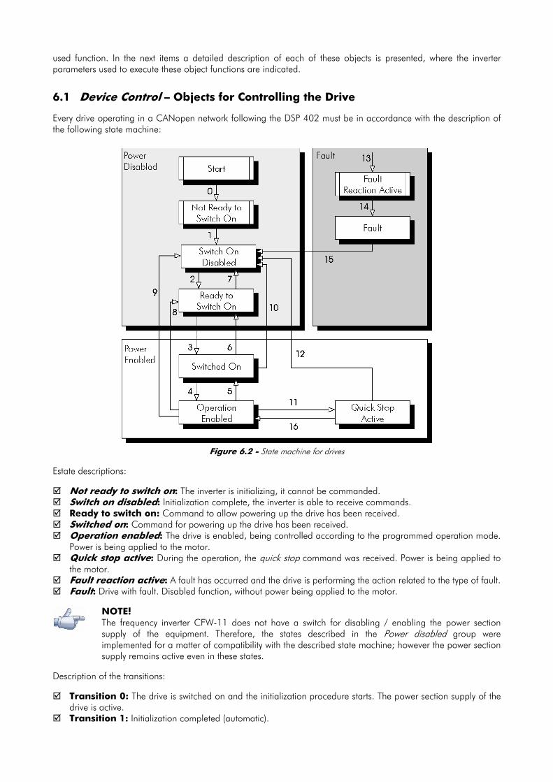
used function. In the next items a detailed description of each of these objects is presented, where the inverter parameters used to execute these object functions are indicated.
6.1 Device Control – Objects for Controlling the Drive Every drive operating in a CANopen network following the DSP 402 must be in accordance with the description of the following state machine:
Figure 6.2 - State machine for drives Estate descriptions:
Not ready to switch on: The inverter is initializing, it cannot be commanded. Switch on disabled: Initialization complete, the inverter is able to receive commands. Ready to switch on: Command to allow powering up the drive has been received. Switched on: Command for powering up the drive has been received. Operation enabled: The drive is enabled, being controlled according to the programmed operation mode.
Power is being applied to the motor. Quick stop active: During the operation, the quick stop command was received. Power is being applied to
the motor. Fault reaction active: A fault has occurred and the drive is performing the action related to the type of fault. Fault: Drive with fault. Disabled function, without power being applied to the motor.
NOTE! The frequency inverter CFW-11 does not have a switch for disabling / enabling the power section supply of the equipment. Therefore, the states described in the Power disabled group were implemented for a matter of compatibility with the described state machine; however the power section supply remains active even in these states.
Description of the transitions:
Transition 0: The drive is switched on and the initialization procedure starts. The power section supply of the drive is active.
Transition 1: Initialization completed (automatic).
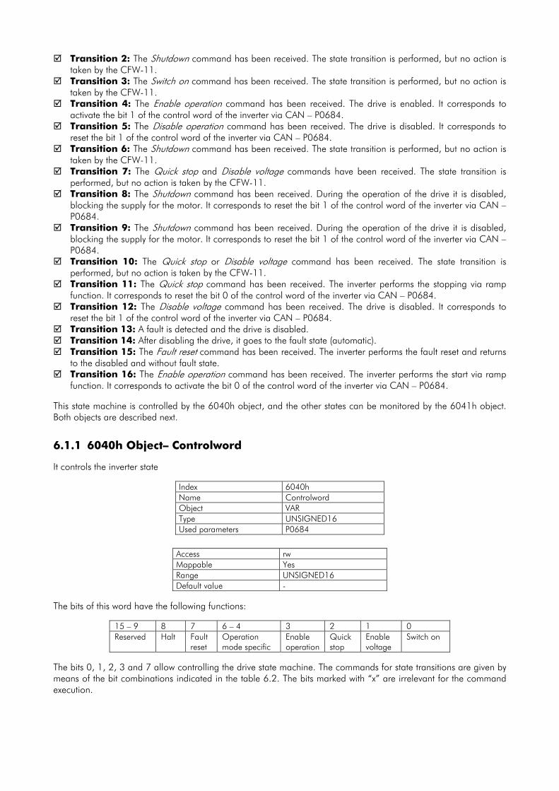
Transition 2: The Shutdown command has been received. The state transition is performed, but no action is taken by the CFW-11.
Transition 3: The Switch on command has been received. The state transition is performed, but no action is taken by the CFW-11.
Transition 4: The Enable operation command has been received. The drive is enabled. It corresponds to activate the bit 1 of the control word of the inverter via CAN – P0684.
Transition 5: The Disable operation command has been received. The drive is disabled. It corresponds to reset the bit 1 of the control word of the inverter via CAN – P0684.
Transition 6: The Shutdown command has been received. The state transition is performed, but no action is taken by the CFW-11.
Transition 7: The Quick stop and Disable voltage commands have been received. The state transition is performed, but no action is taken by the CFW-11.
Transition 8: The Shutdown command has been received. During the operation of the drive it is disabled, blocking the supply for the motor. It corresponds to reset the bit 1 of the control word of the inverter via CAN – P0684.
Transition 9: The Shutdown command has been received. During the operation of the drive it is disabled, blocking the supply for the motor. It corresponds to reset the bit 1 of the control word of the inverter via CAN – P0684.
Transition 10: The Quick stop or Disable voltage command has been received. The state transition is performed, but no action is taken by the CFW-11.
Transition 11: The Quick stop command has been received. The inverter performs the stopping via ramp function. It corresponds to reset the bit 0 of the control word of the inverter via CAN – P0684.
Transition 12: The Disable voltage command has been received. The drive is disabled. It corresponds to reset the bit 1 of the control word of the inverter via CAN – P0684.
Transition 13: A fault is detected and the drive is disabled. Transition 14: After disabling the drive, it goes to the fault state (automatic). Transition 15: The Fault reset command has been received. The inverter performs the fault reset and returns
to the disabled and without fault state. Transition 16: The Enable operation command has been received. The inverter performs the start via ramp
function. It corresponds to activate the bit 0 of the control word of the inverter via CAN – P0684. This state machine is controlled by the 6040h object, and the other states can be monitored by the 6041h object. Both objects are described next.
6.1.1 6040h Object– Controlword It controls the inverter state
Index 6040h Name Controlword Object VAR Type UNSIGNED16 Used parameters P0684
Access rw Mappable Yes Range UNSIGNED16 Default value -
The bits of this word have the following functions:
15 – 9 8 7 6 – 4 3 2 1 0 Reserved Halt Fault
reset Operation mode specific
Enable operation
Quick stop
Enable voltage
Switch on
The bits 0, 1, 2, 3 and 7 allow controlling the drive state machine. The commands for state transitions are given by means of the bit combinations indicated in the table 6.2. The bits marked with “x” are irrelevant for the command execution.

Table 6.2 - Control word Commands
Control word bits Command
Fault reset Enable
operation Quick stop Enable voltage Switch on
Transitions
Shutdown 0 × 1 1 0 2, 6, 8 Switch on 0 0 1 1 1 3 Disable voltage 0 × × 0 × 7, 9, 10, 12 Quick stop 0 × 0 1 × 7, 10, 11 Disable operation 0 0 1 1 1 5 Enable operation 0 1 1 1 1 4, 16 Fault reset 0 → 1 × × × × 15
The bits 4, 5, 6 and 8 have different functions according to the used operation mode. The detailed description of the functions of these bits for the velocity mode is presented on the section 6.2.1.
6.1.2 6041h Object– Statusword
It indicates the CFW-11 present state.
Index 6041h Name Statusword Object VAR Type UNSIGNED16 Used parameters P0680
Access ro Mappable Yes Range UNSIGNED16 Default value -
The bits of this word have the following functions:
Table 6.3 - Statusword bit functions
Bit Description 0 Ready to switch on 1 Switched on 2 Operation enabled 3 Fault 4 Voltage enabled 5 Quick stop 6 Switch on disabled 7 Warning 8 Reserved 9 Remote 10 Target reached 11 Internal limit active
12 – 13 Operation mode specific 14 – 15 Reserved
In this word the bits 0, 1, 2, 3, 5 and 6 indicate the state of the device according to the state machine described in the Figure 6.2. The Table 6.4 describes the combinations of these bits for the state indications. The bits marked with “x” are irrelevant for the state indication.
Table 6.4 - Drive states indicated through the Statusword
Value (binary) State xxxx xxxx x0xx 0000 Not ready to switch on xxxx xxxx x1xx 0000 Switch on disabled xxxx xxxx x01x 0001 Ready to switch on xxxx xxxx x01x 0011 Switched on xxxx xxxx x01x 0111 Operation enabled xxxx xxxx x00x 0111 Quick stop active xxxx xxxx x0xx 1111 Fault reaction active xxxx xxxx x0xx 1000 Fault

The other bits indicate a specific condition for the drive.
Bit 4 – Voltage enabled: indicates that the drive power section is being fed. Bit 7 – Warning: It is not used for the CFW-11. Bit 9 – Remote: indicates when the drive is in the remote mode and accepts commands via the CANopen8
network. It represents the Statusword bit 4 value – P0680. Bit 10 – Target reached: indicates when the drive is operating at the reference value, which depends on
the used operation mode. It is also set to 1 when the functions Quick stop or Halt are activated. Bit 11 – Internal limit active: indicates when the drive is operating at an internal limit value, as current
limit for instance. Bits 12 e 13 – Operation mode specific: they depend on the drive operation mode.
6.1.3 6060h Object– Modes of Operation
It allows programming the CFW-11 operation mode.
Index 6060h Name Modes of operation Object VAR Type INTEGER8 Used parameters -
Access rw Mappable Yes Range INTEGER8 Default value -
The only mode supported by the CFW-11 inverter is the Velocity Mode, represented by the value 2.
6.1.4 6061h Object– Modes of Operation Display
It indicates the CFW-11 operation mode.
Index 6061h Name Modes of operation display Object VAR Type INTEGER8 Used parameters -
Access rw Mappable Yes Range INTEGER8 Default value -
The only mode supported by the CFW-11 inverter is the Velocity Mode, represented by the value 2.
6.2 Velocity Mode – Objects for Controlling the Drive
This operation mode allows the control of the inverter in a simple manner, making available functions of the following type:
Reference value calculation. Capture and monitoring of the speed. Speed limitation. Speed ramps, among other functions.
These functions are executed based on a set of objects for the configuration of that operation mode.
8 It depends on the inverter programming.
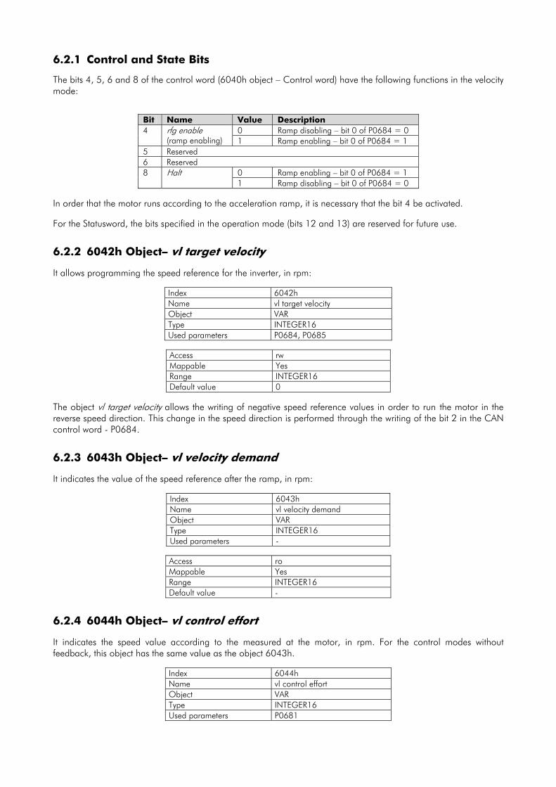
6.2.1 Control and State Bits
The bits 4, 5, 6 and 8 of the control word (6040h object – Control word) have the following functions in the velocity mode:
Bit Name Value Description 0 Ramp disabling – bit 0 of P0684 = 0 4 rfg enable
(ramp enabling) 1 Ramp enabling – bit 0 of P0684 = 1 5 Reserved 6 Reserved
0 Ramp enabling – bit 0 of P0684 = 1 8 Halt 1 Ramp disabling – bit 0 of P0684 = 0
In order that the motor runs according to the acceleration ramp, it is necessary that the bit 4 be activated. For the Statusword, the bits specified in the operation mode (bits 12 and 13) are reserved for future use.
6.2.2 6042h Object– vl target velocity It allows programming the speed reference for the inverter, in rpm:
Index 6042h Name vl target velocity Object VAR Type INTEGER16 Used parameters P0684, P0685
Access rw Mappable Yes Range INTEGER16 Default value 0
The object vl target velocity allows the writing of negative speed reference values in order to run the motor in the reverse speed direction. This change in the speed direction is performed through the writing of the bit 2 in the CAN control word - P0684.
6.2.3 6043h Object– vl velocity demand It indicates the value of the speed reference after the ramp, in rpm:
Index 6043h Name vl velocity demand Object VAR Type INTEGER16 Used parameters -
Access ro Mappable Yes Range INTEGER16 Default value -
6.2.4 6044h Object– vl control effort It indicates the speed value according to the measured at the motor, in rpm. For the control modes without feedback, this object has the same value as the object 6043h.
Index 6044h Name vl control effort Object VAR Type INTEGER16 Used parameters P0681
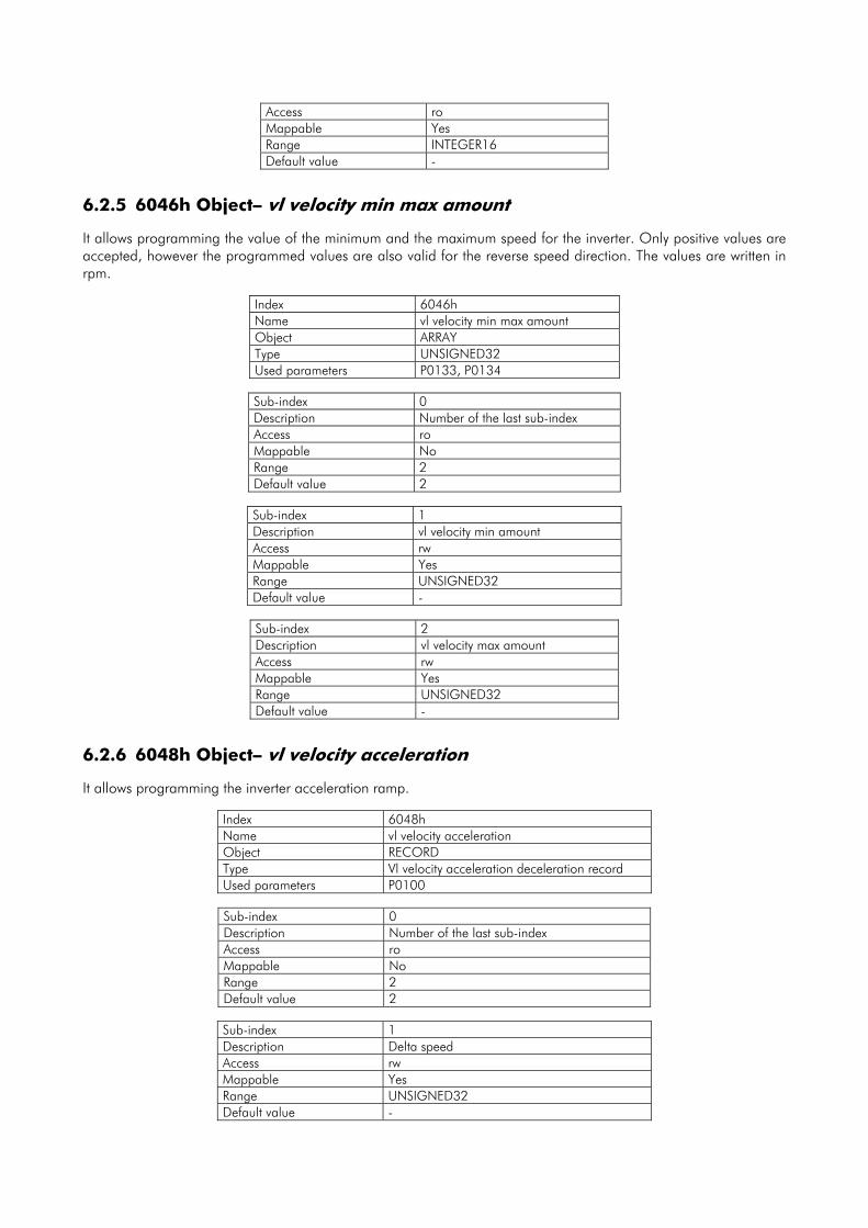
Access ro Mappable Yes Range INTEGER16 Default value -
6.2.5 6046h Object– vl velocity min max amount It allows programming the value of the minimum and the maximum speed for the inverter. Only positive values are accepted, however the programmed values are also valid for the reverse speed direction. The values are written in rpm.
Index 6046h Name vl velocity min max amount Object ARRAY Type UNSIGNED32 Used parameters P0133, P0134
Sub-index 0 Description Number of the last sub-index Access ro Mappable No Range 2 Default value 2
Sub-index 1 Description vl velocity min amount Access rw Mappable Yes Range UNSIGNED32 Default value -
Sub-index 2 Description vl velocity max amount Access rw Mappable Yes Range UNSIGNED32 Default value -
6.2.6 6048h Object– vl velocity acceleration It allows programming the inverter acceleration ramp.
Index 6048h Name vl velocity acceleration Object RECORD Type Vl velocity acceleration deceleration record Used parameters P0100
Sub-index 0 Description Number of the last sub-index Access ro Mappable No Range 2 Default value 2
Sub-index 1 Description Delta speed Access rw Mappable Yes Range UNSIGNED32 Default value -
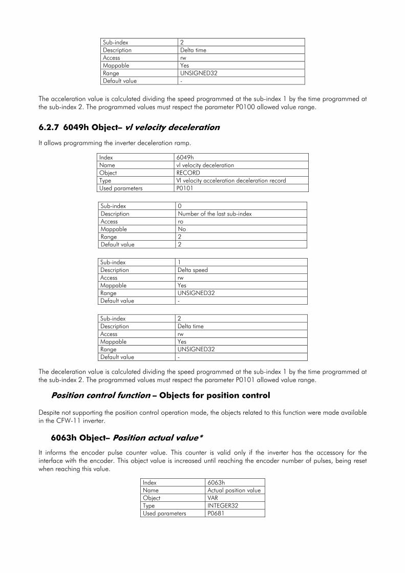
Sub-index 2 Description Delta time Access rw Mappable Yes Range UNSIGNED32 Default value -
The acceleration value is calculated dividing the speed programmed at the sub-index 1 by the time programmed at the sub-index 2. The programmed values must respect the parameter P0100 allowed value range.
6.2.7 6049h Object– vl velocity deceleration It allows programming the inverter deceleration ramp.
Index 6049h Name vl velocity deceleration Object RECORD Type Vl velocity acceleration deceleration record Used parameters P0101
Sub-index 0 Description Number of the last sub-index Access ro Mappable No Range 2 Default value 2
Sub-index 1 Description Delta speed Access rw Mappable Yes Range UNSIGNED32 Default value -
Sub-index 2 Description Delta time Access rw Mappable Yes Range UNSIGNED32 Default value -
The deceleration value is calculated dividing the speed programmed at the sub-index 1 by the time programmed at the sub-index 2. The programmed values must respect the parameter P0101 allowed value range.
Position control function – Objects for position control Despite not supporting the position control operation mode, the objects related to this function were made available in the CFW-11 inverter. 6063h Object– Position actual value*
It informs the encoder pulse counter value. This counter is valid only if the inverter has the accessory for the interface with the encoder. This object value is increased until reaching the encoder number of pulses, being reset when reaching this value.
Index 6063h Name Actual position value Object VAR Type INTEGER32 Used parameters P0681

Access ro Mappable Yes Range 0 up to the encoder
number of pulses minus 1
Default value -
In order to get more information on this function operation, refer to the parameters P0039, P0191 and P0405 in the CFW-11 programming manual.
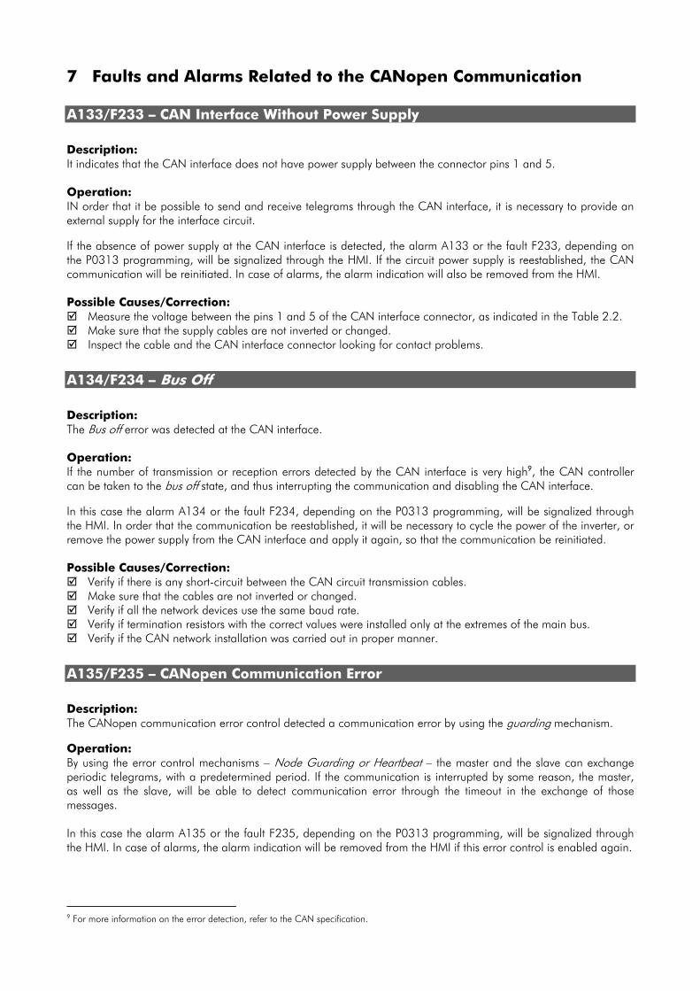
7 Faults and Alarms Related to the CANopen Communication
A133/F233 – CAN Interface Without Power Supply
Description: It indicates that the CAN interface does not have power supply between the connector pins 1 and 5. Operation: IN order that it be possible to send and receive telegrams through the CAN interface, it is necessary to provide an external supply for the interface circuit. If the absence of power supply at the CAN interface is detected, the alarm A133 or the fault F233, depending on the P0313 programming, will be signalized through the HMI. If the circuit power supply is reestablished, the CAN communication will be reinitiated. In case of alarms, the alarm indication will also be removed from the HMI. Possible Causes/Correction:
Measure the voltage between the pins 1 and 5 of the CAN interface connector, as indicated in the Table 2.2. Make sure that the supply cables are not inverted or changed. Inspect the cable and the CAN interface connector looking for contact problems.
A134/F234 – Bus Off
Description: The Bus off error was detected at the CAN interface. Operation: If the number of transmission or reception errors detected by the CAN interface is very high9, the CAN controller can be taken to the bus off state, and thus interrupting the communication and disabling the CAN interface. In this case the alarm A134 or the fault F234, depending on the P0313 programming, will be signalized through the HMI. In order that the communication be reestablished, it will be necessary to cycle the power of the inverter, or remove the power supply from the CAN interface and apply it again, so that the communication be reinitiated. Possible Causes/Correction:
Verify if there is any short-circuit between the CAN circuit transmission cables. Make sure that the cables are not inverted or changed. Verify if all the network devices use the same baud rate. Verify if termination resistors with the correct values were installed only at the extremes of the main bus. Verify if the CAN network installation was carried out in proper manner.
A135/F235 – CANopen Communication Error
Description: The CANopen communication error control detected a communication error by using the guarding mechanism. Operation: By using the error control mechanisms – Node Guarding or Heartbeat – the master and the slave can exchange periodic telegrams, with a predetermined period. If the communication is interrupted by some reason, the master, as well as the slave, will be able to detect communication error through the timeout in the exchange of those messages. In this case the alarm A135 or the fault F235, depending on the P0313 programming, will be signalized through the HMI. In case of alarms, the alarm indication will be removed from the HMI if this error control is enabled again. 9 For more information on the error detection, refer to the CAN specification.

Possible Causes/Correction: Verify the times programmed in both master and slave, for the message exchanging. In order to avoid
problems due to transmission delays and differences in the time counting, it is recommended that the values programmed for message exchanging in the master be a little bit shorter than the times programmed for the error detection by the slave.
Verify if the master is sending the guarding telegrams in the programmed time. Verify communication problems that can cause telegram losses or transmission delays.