campus-wide cooling plant load analysis & thermal energy storage (tes… · 2017-12-15 · bse...
TRANSCRIPT

Campus-Wide Cooling Plant Load Analysis & Thermal Energy Storage (TES) System Concept Engineering Study
Fullerton College
FinalSeptember 8, 2017
North Orange County Community College District

Designing Your Sustainable Future
North Orange County Community College District – Fullerton College Campus-Wide Cooling Plant Load Analysis & TES System Concept Study September 8, 2017 Final Report Page 1
Table of Contents 1 EXECUTIVE SUMMARY ...................................................................................................................... 3
2 EXISTING COOLING PLANT ANALYSIS ............................................................................................. 10
2.1 “Mini Plant” Lot 3 .................................................................................................................... 11
2.1.1 Existing Conditions ........................................................................................................... 12
2.1.2 Existing Distribution Flow Analysis .................................................................................. 12
2.2 1100 / 500 Chiller Plants .......................................................................................................... 13
2.2.1 Existing Conditions ........................................................................................................... 14
2.2.2 Existing Distribution Flow Analysis .................................................................................. 14
2.3 Wilshire Chiller Plant ............................................................................................................... 15
2.3.1 Existing Conditions ........................................................................................................... 15
2.3.2 Existing Distribution Flow Analysis .................................................................................. 16
3 CAMPUS PLANNED GROWTH ......................................................................................................... 18
3.1 Future Block Level Cooling Load Analysis ................................................................................ 18
3.2 Future Distribution Flow Analysis ............................................................................................ 20
3.2.1 Phase I Analysis ................................................................................................................ 21
3.2.2 Phase II Analysis ............................................................................................................... 22
3.3 Future Electrical Load Impact .................................................................................................. 23
4 THERMAL ENERGY STORAGE (TES) STUDY ..................................................................................... 24
4.1 Concept 1 – Full Storage TES Concept (On-Peak & Mid-Peak) ................................................ 25
4.2 Concept 2 – Full Storage TES Concept (On-Peak) .................................................................... 27
4.3 Concept 3 – Partial Storage TES Concept (On-Peak, Mid-Peak, & Off-Peak) .......................... 29
4.4 TES Life Cycle Cost Analysis ..................................................................................................... 31
4.4.1 Energy Analysis Tools ....................................................................................................... 32
4.4.2 Utility Rates and Escalation Rates ................................................................................... 32
4.4.3 Concepts Analyzed ........................................................................................................... 33
4.4.4 Installation and Maintenance Costs, Life Expectancy ..................................................... 33
4.4.5 Summary of Findings ....................................................................................................... 34
4.5 Benefit of a Thermal Energy Storage System .......................................................................... 36
4.6 Energy Incentives Associated with TES System ....................................................................... 37

Designing Your Sustainable Future
North Orange County Community College District – Fullerton College Campus-Wide Cooling Plant Load Analysis & TES System Concept Study September 8, 2017 Final Report Page 2
4.7 Proposed Future Chiller Plant / TES Concepts ......................................................................... 38
4.7.1 Expansion of Central Plant without TES system .............................................................. 38
4.7.2 Concept 1 – Full Storage TES Concept (On-Peak & Mid-Peak) ........................................ 39
4.7.3 Concept 2 – Full Storage TES Concept (On-Peak) ............................................................ 39
4.7.4 Concept 3 – Partial Storage TES Concept (On-Peak, Mid-Peak, & Off-Peak)................... 40
5 ENGINEERING COST ESTIMATES ..................................................................................................... 42
5.1 Engineers Opinion of Cost ....................................................................................................... 42
5.1.1 Base Case – Expansion of Central Plant without TES system .......................................... 42
5.1.2 Concept 1 – Full Storage TES Concept (On-Peak & Mid-Peak) ........................................ 43
5.1.3 Concept 2 – Full Storage TES Concept (On-Peak) ............................................................ 44
5.1.4 Concept 3 – Partial Storage TES Concept (On-Peak, Mid-Peak, & Off-Peak)................... 45
5.1.5 Existing Central Plant Replacement Cost ......................................................................... 46
6 RECOMMENDATIONS...................................................................................................................... 47
Appendix A – CHW Analysis .................................................................................................................... 50
Appendix B - Photos ................................................................................................................................ 51
Appendix C – Utility Rates ...................................................................................................................... 62

Designing Your Sustainable Future
North Orange County Community College District – Fullerton College Campus-Wide Cooling Plant Load Analysis & TES System Concept Study September 8, 2017 Final Report Page 3
1 EXECUTIVE SUMMARY BSE Engineering is pleased to submit the results of this campus-wide cooling plant load analysis & thermal energy storage (TES) system concept engineering study. The purpose of this study is to analyze and validate the adequacy of the existing cooling plants, analyze and determine the future cooling needs of the campus based on the proposed build out as indicated in the “Campus Master Plan”, evaluate TES concepts, sizes, and impact on campus, and provide an engineering cost estimate to assist the campus with project and capital planning.
Based on this engineering study, the existing chiller plants serving the existing campus buildings do not have adequate spare capacity to meet the required cooling needs for the master planned campus facilities. Additionally, in the current chiller plant configurations there is limited spare capacity and there is no redundancy on the chillers to allow for scheduled maintenance and repairs. For example, the central plant in Lot 3 has a total capacity of 1200-tons with a total building connected load of 1,536-tons (78% diversity).
The existing total installed cooling capacity will not be able to support the projected growth, as depicted in the “Fullerton College Facilities Master Plan” as shown below. Additional cooling capacities will be required either in the form of adding new chillers to the existing central plants or a combination of adding new chillers along with some Thermal Energy Storage (TES) capacity.
Figure 1 - Fullerton College Facilities Master Plan

Designing Your Sustainable Future
North Orange County Community College District – Fullerton College Campus-Wide Cooling Plant Load Analysis & TES System Concept Study September 8, 2017 Final Report Page 4
An engineering flow analysis of the existing chilled water piping discovered that some of the existing underground chilled water pipes are undersized and need to be replaced. In order to develop a resilient chilled water infrastructure system, this report recommends the creation of a chilled water loop around the campus and identifies the need to add approximately 3,000 linear feet of trenching for approximately 6,000 linear feet of chilled water piping (3000 feet of supply and 3000 feet of return).
This study recommends the consolidation of all cooling plants into a single location at “Mini Plant” Lot 3 with a TES tank located near the plant. To determine the best possible solution for sizing of the TES tank and for increasing the cooling capacity requirements of the chiller plant at Lot 3, BSE analyzed three TES options and conducted a Life Cycle Cost Analysis (LCCA) comparing these options to a base case of adding chiller capacity to meet the required cooling load. The concept options studies were:
1. Concept 1 – Full Storage TES (On-Peak & Mid-Peak) a. This option would provide cooling for all campus buildings during both On-Peak
(Noon to 6 pm) and Mid-Peak (6 pm to 11 pm & 8 am to Noon) hours.
2. Concept 2 – Full Storage TES (On-Peak) a. This option would provide cooling for all campus buildings only during the On-
Peak (Noon to 6 pm) hours.
3. Concept 3 – Partial Storage TES (On-Peak, Mid-Peak & Off-Peak) a. This option would provide cooling for all campus buildings using a combination
of TES and chiller. Chillers will operate 24/7 to either charge the TES tank or to assist the TES tank in meeting the campus loads.
Concept 2 – Full TES sized to satisfy the On-Peak cooling loads had the best simple pay back at 4.3 years, with savings of $4,694,777 when compared to a non-TES traditional chiller plant.

Designing Your Sustainable Future
North Orange County Community College District – Fullerton College Campus-Wide Cooling Plant Load Analysis & TES System Concept Study September 8, 2017 Final Report Page 5
BSE understands the challenges facing the District as it relates to making major infrastructure changes to the existing chiller plants and the much needed underground piping infrastructure. To assist with the planning and implementation of this work, BSE has developed a preliminary phased implementation plan based on our review of the project schedule showing the proposed buildout to 2023 as follows:
1. Instructional Building/M&O Building – Increase Chiller Capacity to the Mini Plant Lot 3 (To be Completed by 4th Quarter of 2019) – Address the chiller capacity shortage in the Mini Plant Lot 3 by adding a new 600-ton chiller and associated cooling tower. Adding a new 600-ton chiller to the existing 1200-ton plant will provide the capacity needed to add the new Instructional Building and the M&O Building, as well as, providing the needed spare capacity. The chilled water supply and return piping for Instructional Building and M&O will be terminated within a concrete utility vault with isolation valves ready for connection to the proposed buildings.
2. Buildings 300 / 500 – Replace Undersized Chilled Water Piping & Extend Piping (To be Completed by 1st Quarter of 2021) – Remove the existing undersized chilled water supply and return from the Mini Plant Lot 3 to Building 300 with piping provisions to serve Building 500 and the proposed Welcome Center. The chilled water supply and return piping for buildings 500 and Welcome Center will be terminated within a concrete utility vault with isolation valves. Chiller in Building 500 shall be removed and associated underground piping from Building 1100 shall be abandoned in place.
Figure 2 - Buildings 300 / 500 – Replace Undersized Chilled Water Piping & Extend Piping
Provide 10” CHW supply & return
(2,500 LF) as highlighted in red

Designing Your Sustainable Future
North Orange County Community College District – Fullerton College Campus-Wide Cooling Plant Load Analysis & TES System Concept Study September 8, 2017 Final Report Page 6
3. TES & Chilled Water Piping Loop (Upon Approved Funding) – Implement the recommendations of Concept 2 by extending the chilled water piping to the Fine Arts Building, therefore completing the campus chilled water loop, and installing the recommended 932,000 gallon (70’-5” ID x 32’-0” water depth) tank. The chilled water supply and return piping for the proposed Performing Arts Building and existing Wilshire Buildings will be terminated within a concrete utility vault with isolation valves ready for extension.
Figure 3 - TES & Chilled Water Piping Loop
4. Wilshire Buildings (6 Months Prior to Construction of New Buildings) – Extend the chilled water piping from the main campus to the Wilshire Buildings to serve the new Performing Arts Complex, including the second Instructional Building and all other existing buildings. Additional architectural studies will have to be completed in order to determine the best way to route the chilled water piping across Chapman Ave.
Figure 4 - Wilshire Buildings
Install 10” CHW supply & return
completing CHW loop (1,000 LF)
highlighted in red
Install 8” CHW supply & return
(2,500 LF) highlighted in red

Designing Your Sustainable Future
North Orange County Community College District – Fullerton College Campus-Wide Cooling Plant Load Analysis & TES System Concept Study September 8, 2017 Final Report Page 7
As a general recommendation for all upcoming HVAC retrofit or replacement projects, it is critical for the campus to address some of the existing deficiencies associated with the installed cooling coils and the low delta T condition impacting the chiller plant operations. The recommended TES Concept 2 assumes a central plant delta T of 22-degrees. The existing “Mini Plant” Lot 3 central plant is designed at a 12-degree delta T. In order for the new central plant and TES system to operate most efficiently, the existing chilled water coils at each existing building will need to be replaced with new coils that are designed at a minimum 20-degree delta T. Increasing the delta T at the existing buildings will also reduce the chilled water flow, which will help reduce excessive pipe velocities and improve the life expectancy of the chilled water loop.
Fullerton College would be eligible to participate in the Permanent Load Shifting Program (PLS) with Southern California Edison utility company. PLS incentives include eligibility for reimbursements of up to $875 per kilowatt of shifted cooling load or 50% of the total TES system equipment and installation costs (up to $1.5 million), whichever is less.
Based on our current understanding, PLS incentives expire at the end of 2017, however, SCE is still accepting new project reservations provided the installation is completed within 18 months of the approval date. For the purposes of this study, given the uncertainty of the availability of these incentives in the next program cycle, no capital cost reductions are considered in the life cycle cost analysis. The incentives will only make TES installation more attractive and shorten the simple payback periods.

Designing Your Sustainable Future
North Orange County Community College District – Fullerton College Campus-Wide Cooling Plant Load Analysis & TES System Concept Study September 8, 2017 Final Report Page 8
There are a total of twenty (20) existing buildings on campus that are being analyzed in this study as shown in Table 1. Per the Campus Master Plan, it is estimated that five (5) additional new buildings will be added to the campus-wide chilled water system as indicated in Table 2.
Table 1 – Existing Buildings
Building Number Building Name Cooling Load1
[Tons]
Chilled Water Delta T1
[Degrees F]
Chilled Water Flow Rate1
[GPM] 100 Administration 72 10 175
200 College Center / Food Services 155 10 368
300 Business & Computer Info 51 10 121
400 South Science 396 18 529
500 Applied Arts / Humanities 88 10 211
600 North Science 100 12 201
700 Technology & Engineering 191 18 256
800 Library Learning Resource Center 182 DX DX
840 Disability Support Service / Mailroom 30 DX DX
900 Technology & Engineering 85 18 114
1000 Fine Arts / Art Gallery 142 10 312 1100 Music 108 10 259 1200 Physical Education 278 12 612 1300 Theater Arts 135 10 325
1400 Classroom Office Building 188 10 450
2000 Student Services / TV 143 16 214 2100 Wilshire Auditorium 52 16 78
W100 Wilshire Continuing Ed 32 16 48
W200 Wilshire Continuing Ed 54 16 81
W300 Wilshire Continuing Ed 14 12 27
Footnotes: 1. Existing data based on research of available engineering drawings and site investigations.

Designing Your Sustainable Future
North Orange County Community College District – Fullerton College Campus-Wide Cooling Plant Load Analysis & TES System Concept Study September 8, 2017 Final Report Page 9
Table 2 – Planned Future Buildings
Future Building Name Planned Square
Footage [ASF]
Estimated Cooling Load
[Tons]
Estimate Chilled Water Flow Rate
[GPM] Instructional Building 47,900 2061 2744
Maintenance and Operation Building 13,200 462 624
Welcome Center 29,470 1032 1384
Performing Arts Complex 25,658 1353 1804
Instructional Building South of Chapman 35,200 1511 2014
Total: 151,428 641 855 Footnotes:
1. Estimated Cooling Load based on 233 square foot/ton. 2. Estimated Cooling Load based on 285 square foot/ton. 3. Estimated Cooling Load based on 190 square foot/ton. 4. Estimated Flow Rate based on 18 Delta T.
The Child Development Center Complex and Horticulture/Vocational Science Building Complex located at the north end of Fullerton College campus were not considered in the campus-wide cooling plant analysis or TES study. These buildings were excluded based on the distance from the main campus and existing central plants. There is no existing chilled water infrastructure linking the northern part of campus to the main campus chilled water loop.
Designing Your Sustainable Future
North Orange County Community College District – Fullerton College Campus-Wide Cooling Plant Load Analysis & TES System Concept Study September 8, 2017 Final Report Page 10
2 EXISTING COOLING PLANT ANALYSIS Fullerton College campus is currently being supplied chilled water by four chilled water plants, “Mini Plant” Lot 3, 1100 / 500 Chiller Plants, and Wilshire Chiller Plant. “Mini Plant” Lot 3 serves Buildings 200, 400, 600, 700, 900, 1000, 1200, and 1400. The 1100 / 500 Chiller Plants serves Buildings 100, 300, 500, 1100, and 1300. Lastly, the Wilshire Chiller Plant serves Buildings 2000, 2100, W100, W200, and W300. Refer to Table 3 for details on the existing chiller plants.
Table 3 - Existing Chiller Plants
Chiller Plant # of Chillers
# of Towers
Total GPM
Total Tonnage
Delta T [Deg. F]
Total Plant Load [Tons]
Existing Diversity
“Mini Plant” Lot 3
2 3 2400 1200 12 1,536 78%
Bldg 500 1 1 600 300 12 454 66%1
Bldg 1100 2 1 700 350 12 454 77%1
Wilshire 1 1 375 250 16 294 85%
Footnotes: 1. Diversity is based on total load of all buildings associated with building 1100 / 500 Chiller Plants. However, building
1100 chiller plant and building 500 chiller plant can run simultaneously, with building 500 chiller plant supporting building 500 and 1100 chiller plant support the remaining buildings thus increasing the diversity.
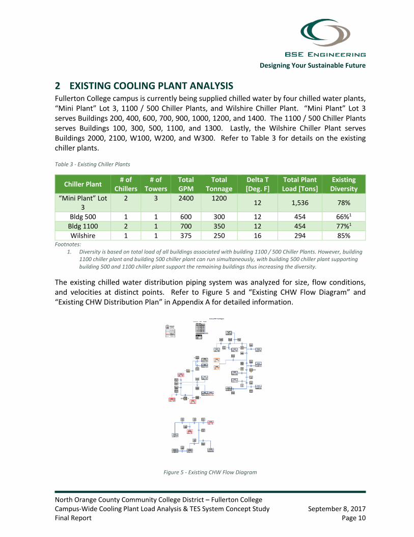
The existing chilled water distribution piping system was analyzed for size, flow conditions, and velocities at distinct points. Refer to Figure 5 and “Existing CHW Flow Diagram” and “Existing CHW Distribution Plan” in Appendix A for detailed information.
Figure 5 - Existing CHW Flow Diagram

Designing Your Sustainable Future
North Orange County Community College District – Fullerton College Campus-Wide Cooling Plant Load Analysis & TES System Concept Study September 8, 2017 Final Report Page 11
It has been assumed that the underground CHW distribution piping is ASTM scheduled 40 PVC pipe. Typically, with schedule 40 PVC piping, it is recommended limiting the pipe flow velocities to maximum 8 feet per second. In our experience, exceeding the recommended velocities will erode the PVC pipes prematurely. Refer to Table 4 for existing flow conditions that exceed the recommended velocity.
Table 4 - Existing Flow Conditions
Location Point (on Flow Diagram)
Nominal Pipe size [in]
Cooling Flow [GPM]
Cooling Velocity [ft/s]
A 10 2097 8.73 B 8 1269 8.33 C 3 201 8.90 D 6 915 10.40 E 6 915 10.40 F 6 704 8.00 G 6 704 8.00
Based on the as-built drawings available and information from campus personnel, all of the existing chillers and cooling towers located on Fullerton College campus were approximately installed around the year 2007, which makes them approximately 10 years old. Per Table 3 - Median Service Life in the 2015 ASHRAE Handbook – HVAC Applications as seen in Figure 6, centrifugal chillers have a median service life of approximately 25 years and metal cooling towers have a median service life of approximately 22 years. Therefore, the chillers and cooling towers are approximately halfway through their expected life usefulness. The chillers installed outdoors are expected to have a slightly shorter service life due to being exposed to weather.
Figure 6 - 2015 ASHRAE Handbook - HVAC Applications Median Service Life
2.1 “Mini Plant” Lot 3 “Mini Plant” Lot 3 chiller plant has a total cooling capacity of 1200-tons and consists of two 600-ton dual centrifugal compressor chillers and three 400-ton induced draft cooling towers.

Designing Your Sustainable Future
North Orange County Community College District – Fullerton College Campus-Wide Cooling Plant Load Analysis & TES System Concept Study September 8, 2017 Final Report Page 12
“Mini Plant” Lot 3 chiller plant provides approximately 57% of the current chilled water cooling capacity for the campus based on building block loads in tons. As seen in Table 3, the existing diversity of “Mini Plant” Lot 3 is 78%, which indicates that the existing plant is at its peak capacity.
2.1.1 Existing Conditions The “Mini Plant” Lot 3 is located on the Northside of campus in parking lot 3. The plant is located in an enclosure with a partial roof. The chillers are located outside underneath a weather cover.
The following was observed (refer to photos in Appendix B):
1. The inside walls of the cooling towers appear to have started to erode. Rust is not yet visible, but will most likely develop in the near future.
2. Condenser water return piping and valve actuator at cooling tower #2 (CT-2) is starting to erode.
3. It appeared that chiller #2 (CH-2) has a leak below the unit.
4. Existing cooling tower capacity is undersized
Recommendations
1. Perform a retro-commissioning on the existing plant
2. Provide cooling towers that are properly sized
2.1.2 Existing Distribution Flow Analysis There are currently eight buildings served by the chilled water distribution piping associated with “Mini Plant” Lot 3, with an estimated total cooling load of 1,536-tons. Refer to Table 5 for information on existing building loads and associated chilled water flow.

Designing Your Sustainable Future
North Orange County Community College District – Fullerton College Campus-Wide Cooling Plant Load Analysis & TES System Concept Study September 8, 2017 Final Report Page 13
Table 5 - “Mini Plant” Lot 3 Existing Building Loads
Building # Building Category
Existing [ASF]
Total Outside
[GSF] Delta T1 Flow1
[GPM]
Cooling Load1
[Tons] SF/Ton1
200 Dining / Offices /
Conference 28,292 41,636 10 368 155 183
400 Labs 39,176 64,924 18 529 396 99
600 Classroom / Offices 16,051 23,694 12 201 100 160
700 Classroom / Offices 53,539 74,154 18 256 191 280
900 Classroom / Offices 22,886 31,688 18 114 85 268
1000 Classroom / Offices 28,656 39,408 10 312 142 202
1200 Office / Mech /
Gym 61,801 98,249 12 612 278 223
1400 Classroom / Offices 24,587 48,949 10 450 188 131
Total: 274,989 422,702 13 2,842 1536 179
Footnotes: 1. Existing data based on research of available engineering drawings and site investigations.
According to our calculations, there are three points on the “Existing CHW Flow Diagram” that exceeds the recommended velocities. These points are A, B, and C as identified on Table 4. Point A occurs at the 10-inch main distribution in between the central plant and building 1400, point B occurs at the 8-inch main distribution in between buildings 1200 and 600, and point C occurs at the 3-inch branch serving building 600.
2.2 1100 / 500 Chiller Plants Building 1100 chiller plant has a total cooling capacity of 350-tons and consists of two 175-ton single centrifugal compressor chillers and one 350-ton induced draft cooling tower. Building 500 chiller plant has a total cooling capacity of 300-tons and consists of one 300-ton dual centrifugal compressor chiller and one 350-ton induced draft cooling tower. 1100 / 500 chiller plants provides approximately 31% of the current chilled water cooling capacity for the campus based on building block loads in tons. As seen in Table 3, the existing diversities of Building 1100 plant Building 500 plant are 77% and 66% respectfully, which indicates that the existing plants are at their peak capacities.

Designing Your Sustainable Future
North Orange County Community College District – Fullerton College Campus-Wide Cooling Plant Load Analysis & TES System Concept Study September 8, 2017 Final Report Page 14
The two chiller plants are connected by a 6-inch chilled water supply/return line that ties the chilled water distribution together. In the existing configuration, the two chiller plants cannot simultaneously serve the same loop. It is our understanding that typically, only one chiller plant operates at a time. However, if both chillers are to operate simultaneously, then the 1100 chiller plant supports buildings 100, 300, 1100, and 1300 and the 500 chiller plant supports the 500 building.
2.2.1 Existing Conditions The building 1100 chiller plant is located in the basement of building 1100 with the cooling tower located on the roof. The building 500 chiller plant is located in the basement of building 500 with the cooling tower located on the roof.
The following was observed (refer to photos in Appendix B):
1. It was observed that chiller #1100-2 (CH-1100-2) evaporator and condenser shells casing is cracking.
2. The BTU meter is not operating correctly for CH-500.
3. During the site visit, CH-500 display panel was not functioning.
Recommendations
3. Fix CH-500 BTU meter.
4. Repair CH-500 display panel.
2.2.2 Existing Distribution Flow Analysis
There are currently five buildings on the chilled water distribution associated with the 1100 / 500 Chiller Plants, with an estimated total cooling load of 454-tons. Refer to Table 6 for information on existing building loads and associated chilled water flow.

Designing Your Sustainable Future
North Orange County Community College District – Fullerton College Campus-Wide Cooling Plant Load Analysis & TES System Concept Study September 8, 2017 Final Report Page 15
Table 6 - 1100 / 500 Chiller Plants Existing Building Loads
Building # Building Category
Existing [ASF]
Total Outside
[GSF] Delta T1 Flow1
[GPM]
Cooling Load1
[Tons] SF/Ton1
Partial 100 General Administrative 1,986 N/A 10 35 14 138
100 Office 16,624 27,925 10 140 58 258
300 Classroom / Offices 14,612 22,705 10 121 51 289
500 Classroom / Offices 22,228 32,746 10 211 88 253
1100 Classroom / Offices 20,278 32,619 10 259 108 188
1300 Theater / Support 25,658 40,300 10 325 135 190
Total: 101,386 156,295 10 1,091 454 223
Footnotes: 1. Existing data based on research of available engineering drawings and site investigations.
According to our calculations, there are four points on the “Existing CHW Flow Diagram” that exceeds the recommended velocities. These points are D, E, F and G as identified on Table 4. Point D occurs at the 6-inch main distribution coming out of building 500 chiller plant, point E occurs at the 6-inch main distribution coming out of building 1100 chiller plant, point F occurs at the 6-inch main line connecting the 500 chiller plant and the 1100 chiller plant, and point G occurs at the 6-inch main distribution in between the 1100 chiller plant and building 1100.
2.3 Wilshire Chiller Plant The Wilshire Chiller Plant has a total cooling capacity of 250-tons and consists of one 250-ton dual centrifugal compressor chiller and one 250-ton induced draft cooling tower. The Wilshire Chiller Plant provides approximately 12% of the current chilled water cooling capacity for the campus based on building block loads in tons. As seen in Table 3, the existing diversity of the Wilshire Chiller Plant is 85%, which indicates that the existing plant has very little spare cooling capacity.
2.3.1 Existing Conditions The Wilshire plant is located on the Southside of campus south of Chapman Ave. The plant is located in an enclosure with no roof. The chiller is located outside underneath a weather cover.

Designing Your Sustainable Future
North Orange County Community College District – Fullerton College Campus-Wide Cooling Plant Load Analysis & TES System Concept Study September 8, 2017 Final Report Page 16
The following was observed (refer to photos in Appendix B):
1. It was observed that chiller #2100 (CH-2100) evaporator and condenser shells casing is cracking.
2. Insulation around shut-off valve for CH-2100 has started to fall off.
3. The primary and secondary pumps (PP 2100-1, PP 2100-2, SP 2100-1, SP 2100-2) are leaking.
4. The inside walls of the cooling tower #2100 (CT-2100) has started to rust.
5. It appeared that chiller #2 (CH-2) has a leak below the unit.
Recommendations
5. Replace insulation around shut-off valve.
6. Replace rusted side panel for CT-2100.
2.3.2 Existing Distribution Flow Analysis There are currently five buildings on the chilled water distribution associated with the Wilshire Chiller Plant, with an estimated total cooling load of 295-tons. Refer to Table 7 for information on existing building loads and associated chilled water flow.

Designing Your Sustainable Future
North Orange County Community College District – Fullerton College Campus-Wide Cooling Plant Load Analysis & TES System Concept Study September 8, 2017 Final Report Page 17
Table 7 - Wilshire Chiller Plant Existing Building Loads
Building # Building Category
Existing [ASF]
Total Outside
[GSF] Delta T1 Flow1
[GPM]
Cooling Load1
[Tons] SF/Ton1
2000 Labs 25,139 39,084 16 214 143 176
2100 Dining / Offices /
Conference 8,804 13,903 16 78 52 169
W100 Classroom 6,000 7,500 16 48 32 189
W200 Classroom 10,960 13,700 16 81 54 203
W300 Classroom 3,680 4,600 12 27 14 271
Total: 54,583 78,787 15.8 448 295 185
Footnotes: 1. Existing data based on research of available engineering drawings and site investigations.
According to our calculations, there are no points on the “Existing CHW Flow Diagram” that exceeds the recommended velocities. Existing piping appears to be sized adequately for existing chilled water flow.

Designing Your Sustainable Future
North Orange County Community College District – Fullerton College Campus-Wide Cooling Plant Load Analysis & TES System Concept Study September 8, 2017 Final Report Page 18
3 CAMPUS PLANNED GROWTH In conjunction with our assessment, the Fullerton College provided the Facility Master Plan outlining anticipated projects, improvements, buildings scheduled for demolition, and the campus future needs. An estimated 151,428 square feet of conditioned floor area is projected to be added to the campus, while an estimated 73,061 square feet of conditioned floor area is to be removed from campus. Additionally, 62,245 square feet of existing conditioned floor area at buildings 800 and 840 is being converted from DX equipment to chilled water, which was not considered in the Facility Master Plan.
This study is broken up into two phases of campus growth. Phase I includes the analysis of the addition of the first three future proposed buildings, which include the Maintenance and Operation (M&O) building, the Instructional building, and Instructional building South of Chapman. Phase II is the analysis of the remaining future proposed campus growth with the addition of the Welcome Center building, the Performing Arts Complex, converting buildings 800 and 840 from direct expansion (DX) equipment to chilled water equipment, as well as the demolition of the existing buildings 1100, 1300, 2000, and partial building 100.
3.1 Future Block Level Cooling Load Analysis A total of 853-tons of new building loads is estimated to be added to the campus chilled water system. An estimated 400-tons of building load is to be removed from the chilled water system. Refer to Table 8 for Phase I estimated building loads being added, Table 9 for Phase II estimated building loads being added, and Table 10 for Phase II estimated building loads being removed.
It is estimated that Phase I will add 403-tons of new building loads with no building load being removed. It is estimated that Phase II will add 450-tons of new building loads and remove 400-tons. A net total of 453-tons of cooling load to be added to the campus.
The estimated building cooling load is determined by multiplying the assignable square feet (ASF) by the average SF/ton of existing buildings per building category.

Designing Your Sustainable Future
North Orange County Community College District – Fullerton College Campus-Wide Cooling Plant Load Analysis & TES System Concept Study September 8, 2017 Final Report Page 19
Table 8 - Phase I Estimated Building Loads added
Building Name
Building Category
Area [ASF]
Total Outside Area
[GSF]
Delta T
Flow [GPM]
Cooling Load
[Tons] SF/Ton
Instructional Building Classroom 47,900 72,400 18 274 2061 233
M&O Building Office 13,200 22,300 18 62 462 285
Instructional Building South
of Chapman Classroom 35,200 54,600 18 201 1511 233
Phase I Total: 96,300 149,300 18 537 403 239 Footnotes:
1. Estimated Cooling Load based on 233 square foot/ton. 2. Estimated Cooling Load based on 285 square foot/ton.
Table 9 - Phase II Estimated Building Loads added
Building Name Building Category
Area [ASF]
Total Outside Area
[GSF]
Delta T
Flow [GPM]
Cooling Load
[Tons] SF/Ton
800 Library 54,6304 67,680 18 242.3 1821 3011
840 Office 7,6154 12,949 18 39.3 301 2581
Welcome Center Office 29,470 44,000 18 139 1032 285
Performing Arts Complex I
Theater / Support 25,658 40,300 18 180 1353 190
Phase II Total: 117,373 164,929 18 601 450 260
Phase I and II Total: 213,673 314,229 18 1,138 853 250 Footnotes:
1. Existing data based on research of available engineering drawings and site investigations. 2. Estimated Cooling Load based on 285 square foot/ton. 3. Estimated Cooling Load based on 190 square foot/ton. 4. Existing DX equipment to chilled water.

Designing Your Sustainable Future
North Orange County Community College District – Fullerton College Campus-Wide Cooling Plant Load Analysis & TES System Concept Study September 8, 2017 Final Report Page 20
Table 10 - Phase II Estimated Building Loads Removed
Building # Building Category
Area [ASF]
Total Outside
[GSF] Delta T Flow
[GPM]
Cooling Load
[Tons] SF/Ton
Partial 100
General Administrative -1,986 - 10 -35 -14 139
1100 Classroom / Office -20,278 -32,619 10 -259 -108 188
1300 Theater / Support -25,658 -40,300 10 -325 -135 190
2000 Labs -25,139 -39,084 16 -214 -143 176
Total: -73,061 -112,003 - - -400 183
Phase I and II Net Total: 140,612 202,226 - - 453 310
Table 11 - Total Estimated Campus Chilled Water Load
Chiller Plant / Phase Area [ASF]
Total Outside [GSF]
Cooling Load [Tons] SF/Ton
Existing “Mini Plant” Lot 3 274,989 422,702 1,536 179
Existing 1100 / 500 Plant 101,386 156,295 454 223 Existing Wilshire Plant 54,583 78,787 295 185 Future Phase I and II 140,612 202,226 453 310
Future Campus Total: 571,570 860,010 2,738 208
3.2 Future Distribution Flow Analysis As done for the existing distribution flow analysis, the future chilled water distribution piping system was analyzed for size, flow conditions, and velocities at distinct points. Refer to Figure 7 and Figure 8 and “CHW Flow Diagram – Phase I”, “Flow Diagram – Phase II”, and “Future CHW Piping Distribution Plan” in Appendix A for detailed information.

Designing Your Sustainable Future
North Orange County Community College District – Fullerton College Campus-Wide Cooling Plant Load Analysis & TES System Concept Study September 8, 2017 Final Report Page 21
Figure 7 - CHW Flow Diagram - Phase I
Figure 8 - CHW Flow Diagram - Phase II
It has been assumed that the underground CHW distribution piping is ASTM scheduled 40 PVC pipe. Typically, with schedule 40 PVC piping, it is recommended limiting the pipe flow velocities to maximum 8 feet per second. In our experience, exceeding the recommended velocities will erode the PVC pipes prematurely.
3.2.1 Phase I Analysis In phase I, the Maintenance & Operating building and the Instructional building are added to the “Mini Plant” Lot 3 chiller plant and chilled water distribution. Per Table 8, an estimated 62 gallons/minute is to be added for the M&O building and an estimated 274 gallons/minute is to be added for the instructional building.
According to our calculations, there are nine points on the “CHW Flow Diagram – Phase I” that exceeds the recommended velocities. These points are A through I as identified on Table 12. Points B through G have no changed from the existing flow analysis. The chilled water velocity at point A has increased form 8.73 ft/s to 9.76 ft/s. Points H and I are two new points that have developed with the addition of the Phase I buildings. Point H occurs at the main 12” distribution piping in between “Mini Plant” Lot 3 and the new M&O building. Point I occurs at the 10” distribution piping in between building 1400 and the new Instructional building.

Designing Your Sustainable Future
North Orange County Community College District – Fullerton College Campus-Wide Cooling Plant Load Analysis & TES System Concept Study September 8, 2017 Final Report Page 22
Table 12 - Phase I Flow Conditions
Location Point (on Flow Diagram)
Nominal Pipe size [in]
Cooling Flow [GPM]
Cooling Velocity [ft/s]
A 10 2097 9.76 B 8 1269 8.33 C 3 201 8.90 D 6 915 10.40 E 6 915 10.40 F 6 704 8.00 G 6 704 8.00 H 12 2276 8.06 I 10 2155 8.97
Instructional building south of Chapman is not in close vicinity to any of the existing chilled water distribution piping, so it is no included in the Phase I flow analysis. However, it is recommended that DX equipment is designed and installed at this building with future provisions to add a chilled water coil. The intent being that this building can be added to the main chilled water distribution piping during Phase II. Per Table 8, an estimated 201 gallons/minute of chilled water would be required to meet the building cooling load.
3.2.2 Phase II Analysis In Phase II, the remaining future proposed buildings are added to the campus, buildings 800 and 840 and the Instructional building South of Chapman are converted from DX equipment to chilled water, and buildings 1100, 1300, 2000, and partial 100 are demolished.
During Phase II of Fullerton College campus growth, it is assumed that the chiller plants are consolidated into a single chiller plant located in Lot 3 and a chilled water distribution loop is developed. Refer to the “CHW Flow Diagram – Phase II” in appendix A.
According to our calculations, there are five points on the “CHW Flow Diagram – Phase II” that exceeds the recommended velocities. These points are A, C, H, J, and K as identified on Table 13. With the chilled water loop, point A velocity has decrease slightly since Phase I from 9.76 ft/s to 9.57 ft/s. Point B and I no longer exceeds the recommended velocity of 8 ft/s. The velocity at point C has not change since the existing flow analysis. Points D through G no longer exits since buildings 1100 and 1300 have been demolished. The chilled water velocity at point H has increased since Phase I from 8.06 ft/s to 12.11 ft/s. Points J and K are two new points that have developed with the addition of the Phase II buildings and chilled water loop. Point J occurs at the main 12” distribution piping right after new M&O building. Point K occurs at the 12” distribution piping coming out of the “Mini Plant” Lot 3 chiller plant.

Designing Your Sustainable Future
North Orange County Community College District – Fullerton College Campus-Wide Cooling Plant Load Analysis & TES System Concept Study September 8, 2017 Final Report Page 23
Table 13 - Phase II Flow Conditions
Location Point (on Flow Diagram)
Nominal Pipe size [in]
Cooling Flow [GPM]
Cooling Velocity [ft/s]
A 10 2097 9.57 B 8 1269 6.152
C 3 201 8.90 D1 0 0 0
E1 0 0 0
F1 0 0 0
G1 0 0 0
H 12 2276 12.11 I 10 2155 6.112
J 12 4110 11.93 K 12 4172 12.11
Footnotes: 1. Piping removed from Flow Diagram during Phase II 2. No longer exceeds recommended velocity of 8 feet per second.
3.3 Future Electrical Load Impact Based on the information received from the District documenting the existing site utilities, as prepared by PSOMAS, there may be an existing spare conduit (SP-5) connecting the main electrical service entry point (labeled Boiler House 1700) and the “Mini Plant” Lot 3. This conduit could be used to extend power to the new chiller plant for the proposed 600-ton chiller. BSE is waiting of further clarification on the size of the conduit prior to finalizing this section of the report. Alternatively, if the spare conduit is not available as shown, then there is an existing 5 inch conduit serving the existing equipment which can be used to supply power to both the existing and the new chiller equipment.
It is recommended that a temporary emergency generator be used during the implementation phase of the chiller plant expansion to allow for the continuous operation of the existing chiller plant during all occupied hours.

Designing Your Sustainable Future
North Orange County Community College District – Fullerton College Campus-Wide Cooling Plant Load Analysis & TES System Concept Study September 8, 2017 Final Report Page 24
4 THERMAL ENERGY STORAGE (TES) STUDY Two full storage TES and one partial storage TES concept was considered in this study. A full storage TES system is one that is sized based on design peak day and allows the central plants chillers and cooling towers to turn completely off for a certain period of time. Typically, the chiller plant associated with a full storage TES system will turn off during the utility company’s on-peak and mid-peak hours. A partial storage TES system is one that is sized based on design peak day and minimizes the chiller plant size by operating 24/7 at a constant rate.
All three concepts are based on thermal stratification thermal storage technology. During the TES charging period, the chiller plant supplies chilled water to the TES tank at low-level and the TES tank returns a portion of the warmer chilled water from the top of the tank. During the TES discharging period, the TES tank supplies chilled water to the campus building load and chilled water return is returned to the top of the tank. Specially designed internal diffusers are used to create a fully stratified system.
The following equation is used to properly size a TES tank:
𝑉𝑉 = 𝑋𝑋12,000 Btu/ton − hours𝐶𝐶𝑃𝑃∆𝑡𝑡 x SG(62.4 lb/ft3)eff
where
V = TES tank volume, ft3
X = amount of thermal capacity required, ton-h
𝐶𝐶𝑃𝑃 = specific heat of water, 1 Btu/𝑙𝑙𝑙𝑙𝑚𝑚 ℉
∆𝑡𝑡 = temperature difference, assumed to be 18℉
SG = specific gravity
eff = storage efficiency, assumed to be 0.9
Equation 1 - TES Tank Sizing
To obtain the estimated future campus hourly chilled water load [tons], a campus model was created using Energy Pro version 7.1 as published by Energy Soft. LLC. The model includes all buildings in Phase II to obtain the future campus load profile. Each building was inputted as a block load in the model. The estimated future hourly chilled water load profile is used to determine the amount of thermal capacity [ton-hours] that is required.

Designing Your Sustainable Future
North Orange County Community College District – Fullerton College Campus-Wide Cooling Plant Load Analysis & TES System Concept Study September 8, 2017 Final Report Page 25
4.1 Concept 1 – Full Storage TES Concept (On-Peak & Mid-Peak) The first proposed TES system concept is to provide a full storage TES tank that is sized to allow the central plant, with the exception of the chilled water distribution pumps, to completely turn off during Southern California Edison’s (SCE) On-Peak and Mid-peak periods. These periods occur from 8:00 a.m. to 11:00 p.m.
According to our calculations, the amount of thermal capacity required is 19,647 ton-hours as highlighted in Table 14 below. Figure 9 below illustrates the campus chilled water load profile as well as the required chiller output to meet the campus load.

Designing Your Sustainable Future
North Orange County Community College District – Fullerton College Campus-Wide Cooling Plant Load Analysis & TES System Concept Study September 8, 2017 Final Report Page 26
Table 14 - TES Concept 1 - Peak Day Full-Storage TES Sizing Calculation
Chiller Output [Tons] TES Charge [Ton-hours]1:00 AM 100 2352 62942:00 AM 76 2352 85703:00 AM 71 2352 108514:00 AM 57 2352 131465:00 AM 61 2352 154366:00 AM 55 2352 177337:00 AM 438 2352 196478:00 AM 1106 0 185419:00 AM 1349 0 17193
10:00 AM 1539 0 1565311:00 AM 1599 0 1405412:00 PM 1658 0 123971:00 PM 1742 0 106542:00 PM 1837 0 88173:00 PM 1614 0 72034:00 PM 1376 0 58275:00 PM 1295 0 45326:00 PM 1161 0 33717:00 PM 1096 0 22768:00 PM 1002 0 12739:00 PM 843 0 430
10:00 PM 430 0 011:00 PM 356 2352 199612:00 AM 306 2352 4042
Total 21169 21169
Time of Day Campus Hourly CHW Load [Tons]Chilled Water TES System

Designing Your Sustainable Future
North Orange County Community College District – Fullerton College Campus-Wide Cooling Plant Load Analysis & TES System Concept Study September 8, 2017 Final Report Page 27
Figure 9 - TES Concept 1
In order to meet the campus future load with TES Concept 1, the central plant would be required to double in capacity from 1,200-tons to 2,400-tons.
Per Equation 1, the TES Concept 1 requires a chilled water thermal energy storage tank with a net total volume of 233,229 ft3 or 1.75 million gallons.
4.2 Concept 2 – Full Storage TES Concept (On-Peak) The second proposed TES system concept is to provide a full storage TES tank that is sized to allow the central plant, with the exception of the chilled water distribution pumps, to completely turn off during SCE’s On-Peak time period only. This time period occur from noon to 6:00 p.m.
According to our calculations, the amount of thermal capacity required is 10,481 ton-hours as highlighted in Table 15 below. Figure 10 below illustrates the campus chilled water load profile as well as the required chiller output to meet the campus load.

Designing Your Sustainable Future
North Orange County Community College District – Fullerton College Campus-Wide Cooling Plant Load Analysis & TES System Concept Study September 8, 2017 Final Report Page 28
Table 15 - TES Concept 2 - Peak Day Full-Storage TES Sizing Calculation
Chiller Output [Tons] TES Charge [Ton-hours]1:00 AM 100 1176 41142:00 AM 76 1176 52143:00 AM 71 1176 63194:00 AM 57 1176 74375:00 AM 61 1176 85526:00 AM 55 1176 96737:00 AM 438 1176 104118:00 AM 1106 1176 104819:00 AM 1349 1176 10308
10:00 AM 1539 1176 994511:00 AM 1599 1176 952212:00 PM 1658 0 78641:00 PM 1742 0 61222:00 PM 1837 0 42853:00 PM 1614 0 26714:00 PM 1376 0 12955:00 PM 1295 0 06:00 PM 1161 1176 157:00 PM 1096 1176 958:00 PM 1002 1176 2699:00 PM 843 1176 602
10:00 PM 430 1176 134811:00 PM 356 1176 216812:00 AM 306 1176 3038
Total 21169 21169
Chilled Water TES SystemCampus Hourly CHW Load [Tons]Time of Day

Designing Your Sustainable Future
North Orange County Community College District – Fullerton College Campus-Wide Cooling Plant Load Analysis & TES System Concept Study September 8, 2017 Final Report Page 29
Figure 10 - TES Concept 2
In order to meet the campus future load with TES Concept 2, the existing 1,200-ton central plant can be re-purposed to operate with a TES system, by increasing the central delta T from 12-deg F. to 18-Deg F.
Per Equation 1, the TES Concept 2 requires a chilled water thermal energy storage tank with a net total volume of 124,420 ft3 or 930,725 gallons.
4.3 Concept 3 – Partial Storage TES Concept (On-Peak, Mid-Peak, & Off-Peak) The third proposed TES system concept is to provide a partial storage TES tank that is sized to allow for the smallest possible chilled water central plant, which is designed to run throughout the entire day. The central plant is intended to operate at a constant rate during SCE’s On-Peak, Mid-Peak, and Off-Peak Hours.
According to our calculations, the amount of thermal capacity required is 6,908 ton-hours as highlighted in Table 16 below. Figure 11 below illustrates the campus chilled water load profile as well as the required chiller output to meet the campus load.

Designing Your Sustainable Future
North Orange County Community College District – Fullerton College Campus-Wide Cooling Plant Load Analysis & TES System Concept Study September 8, 2017 Final Report Page 30
Table 16 - TES Concept 3 - Peak Day Full-Storage TES Sizing Calculation
Chiller Output [Tons] TES Charge [Ton-hours]1:00 AM 100 882 23742:00 AM 76 882 31813:00 AM 71 882 39924:00 AM 57 882 48165:00 AM 61 882 56376:00 AM 55 882 64637:00 AM 438 882 69088:00 AM 1106 882 66849:00 AM 1349 882 6217
10:00 AM 1539 882 556011:00 AM 1599 882 484312:00 PM 1658 882 40671:00 PM 1742 882 32072:00 PM 1837 882 22523:00 PM 1614 882 15204:00 PM 1376 882 10265:00 PM 1295 882 6136:00 PM 1161 882 3347:00 PM 1096 882 1208:00 PM 1002 882 09:00 PM 843 882 39
10:00 PM 430 882 49111:00 PM 356 882 101712:00 AM 306 882 1593
Total 21169 21169
Time of Day Campus Hourly CHW Load [Tons]Chilled Water TES System

Designing Your Sustainable Future
North Orange County Community College District – Fullerton College Campus-Wide Cooling Plant Load Analysis & TES System Concept Study September 8, 2017 Final Report Page 31
Figure 11 - TES Concept 3
In order to meet the campus future load with TES Concept 3, the existing 1,200-ton central plant can be re-purposed to operate with a TES system, by increasing the central delta T from 12-deg F. to 18-Deg F and operating the central plant at part load conditions.
Per Equation 1, the TES Concept 3 requires a chilled water thermal energy storage tank with a net total volume of 82,001 ft3 or 613,407 gallons.
4.4 TES Life Cycle Cost Analysis A quantitative and qualitative study was conducted with the objective of performing a life cycle cost analysis of Phase II campus growth comparing the following proposed concepts:
• Base Case – Expansion of Central Chiller Plant with no TES System
• Concept 1 – Expansion of Central Chiller Plant with a Full Storage TES S(On-Peak & Mid-Peak)
• Concept 2 – Expansion of Central Chiller Plant with a Full Storage TES System (On-Peak)
• Concept 3 – Expansion of Central Chiller Plant with a Partial Storage TES System

Designing Your Sustainable Future
North Orange County Community College District – Fullerton College Campus-Wide Cooling Plant Load Analysis & TES System Concept Study September 8, 2017 Final Report Page 32
4.4.1 Energy Analysis Tools The Fullerton College campus buildings and TES systems were modeled using Energy Pro version 7.1 as published by Energy Soft. LLC. Energy Pro is a comprehensive energy-analysis program used to perform the energy analysis and life cycle cost analysis in this study.
The study period is carried for 20 years starting January of 2018. The study assumed a real discount rate of 3% and DOE/FEMP escalation rates based on the Western United States region.
4.4.2 Utility Rates and Escalation Rates Southern California Edison provided historical electric utility data for Fullerton College. The current rate structure that serves the main campus is a Time of Use (TOU) rate structure, specifically TOU-8 Option B. Since this life cycle cost analysis is comparing TES systems, it is assumed that the campus will update their electric utility service to SCE’s TOU-8 Option A, which is a rate structure available for customers who participates in the Permanent Load Shifting program. The base case was modeled using the existing TOU-8 Option B rate schedule. Refer to Appendix C for SCE’s rate schedules.
Based on SCE’s current TOU-8 Option A rate structure, the following usage charges have been assumed:
• Summer Season (12:00 a.m. on June 1 through 12:00 a.m. on October 1 of each year)
o On-Peak (Noon to 6:00 p.m.) - $0.27462/kWh
o Mid-Peak (8:00 a.m. to noon and 6:00 p.m. to 11:00 p.m.) - $0.07542/kWh
o Off-Peak (All other hours) - $0.03165/kWh
• Winter Season (12:00 a.m. on October 1 through 12:00 a.m. on June 1 of each year)
o On-Peak – N/A
o Mid-Peak (8:00 a.m. to 9:00 p.m.) - $0.04579/kWh
o Off-Peak (All other hours) - $0.03645/kWh
• Facilities Related Demand Charge - $18.34/kW
This analysis should be viewed as a comparative analysis comparting the three alternate TES systems with the goal of selecting the system with the lowest total cost of ownership.

Designing Your Sustainable Future
North Orange County Community College District – Fullerton College Campus-Wide Cooling Plant Load Analysis & TES System Concept Study September 8, 2017 Final Report Page 33
4.4.3 Concepts Analyzed Base Case – Expansion of Central Chiller Plant with no TES System
The base case was modeled without the installation of a TES system. In order to meet the estimated campus future chilled water load, the existing campus plant has to be increased in size.
4.4.4 Installation and Maintenance Costs, Life Expectancy Refer to Engineering Cost Estimates in section 5 for a breakdown of cost.
Base Case
• Installation cost $3,881,914 • Annual recurring maintenance cost $63,208 • Non annual recurring maintenance cost (Every 5 years) $60,000 • Existing central plant replacement cost $1,893,814 • Centrifugal Chiller life expectancy 25 years • Metal Cooling Tower life expectancy 22 years • Pumps life expectancy 20 years
Concept 1
• Installation cost $8,528,366 • Annual recurring maintenance cost $63,208 • Non annual recurring maintenance cost (Every 5 years) $60,000 • Existing central plant replacement cost $1,893,814 • Centrifugal Chiller life expectancy 25 years • Metal Cooling Tower life expectancy 22 years • Pumps life expectancy 20 years
Concept 2
• Installation cost $5,858,138 • Annual recurring maintenance cost $65,000 • Non annual recurring maintenance cost (Every 5 years) $45,000 • Existing central plant replacement cost $1,893,814 • Centrifugal Chiller life expectancy 25 years • Metal Cooling Tower life expectancy 22 years • Pumps life expectancy 20 years
Concept 3

Designing Your Sustainable Future
North Orange County Community College District – Fullerton College Campus-Wide Cooling Plant Load Analysis & TES System Concept Study September 8, 2017 Final Report Page 34
• Installation cost $4,951,597 • Annual recurring maintenance cost $75,000 • Non annual recurring maintenance cost (Every 5 years) $40,000 • Existing central plant replacement cost $1,893,814 • Centrifugal Chiller life expectancy 25 years • Metal Cooling Tower life expectancy 22 years • Pumps life expectancy 20 years
4.4.5 Summary of Findings Base Case
• Electric Annual Consumption 17,402,969 kWh • Life Cycle Cost Total $34,135,536
Concept 1
• Electric Annual Consumption 14,162,387 kWh • Life Cycle Cost Total $31,447,738 • Net saving compared to base case $2,687,798 • Simple payback 9.3 years
Concept 2
• Electric Annual Consumption 14,333,097 kWh • Life Cycle Cost Total $29,440,760 • Net saving compared to base case $4,694,777 • Simple payback 4.3 years
Concept 3
• Electric Annual Consumption 13,804,970 kWh • Life Cycle Cost Total $32,440,760 • Net saving compared to base case $1,764,850 • Simple payback 4.9 years

Designing Your Sustainable Future
North Orange County Community College District – Fullerton College Campus-Wide Cooling Plant Load Analysis & TES System Concept Study September 8, 2017 Final Report Page 35

Designing Your Sustainable Future
North Orange County Community College District – Fullerton College Campus-Wide Cooling Plant Load Analysis & TES System Concept Study September 8, 2017 Final Report Page 36
4.5 Benefit of a Thermal Energy Storage System The purpose of a thermal energy storage system is to produce and store chilled water during the off-peak electrical demand period and then distribute the chilled water from the thermal storage tank to the campus during the peak electrical demand period. The following benefits are to be considered by NOCCCD:
Reduced Costs
A TES system reduces energy and operation costs by reducing the peak electric demand, participating in Southern California Edison Permanent Load Shifting Program, and reduces electric usage by shifting the electric power consumption from daytime to nighttime.
Future Campus Growth
As Fullerton Campus grows, so does the campus cooling loads. A TES system can be designed to meet the future cooling loads, which will avoid capital expenses of adding new chillers, cooling towers, and pumps.
Increased Cooling Plant Efficiency
The energy performance of the chillers can be increased with a TES system because the chillers would be designed at a higher delta T, they would be operating at lower wet bulb-temperatures, and the chillers would be operating nearer to the design point more of the time.
The cooling towers also can benefit from a TES system because of free-cooling cycle applications. With the lower wet bulb nighttime temperatures, the TES system allows the tower free-cooling cycle to produce more cooling capacity.
Lower Pump Horsepower
The high delta T used in TES systems reduces the flow requirements. As a result, smaller pumps are required to distribute the chilled water and saving the district money by reducing pump consumption.
Smaller Chilled Water Pipes
A TES system designed at a higher delta T reduces the flow requirements, which allows for smaller chilled water pipes to be utilized. This is very important for a campus with increasing cooling loads because the existing chilled water piping has the potential to be re-used with a higher designed delta T system. Money saved by re-using the existing chilled water distribution system and by installing smaller piping and insulation were required.

Designing Your Sustainable Future
North Orange County Community College District – Fullerton College Campus-Wide Cooling Plant Load Analysis & TES System Concept Study September 8, 2017 Final Report Page 37
High Reliability
Adding a TES system increases the cooling plant reliability because the campus will no longer depend on instantaneous production of chilled water. If a chiller goes down temporarily and needs to be repaired, chilled water can still be distributed from the tank, while the chiller is being serviced.
Lower Maintenance Cost
TES systems generally use smaller chillers, cooling towers, and pumps than conventional systems, which has the potential to help reduce the maintenance costs associated with a chilled water plant. Any maintenance required on the plant can be done during the day because the chillers will not be operating during the peak electric demand period.
Use as a Fire Suppression Reservoir
A chilled water TES tank can be considered as a reservoir that can be used as a fire suppression source if approved by fire marshal. Special nozzles can be installed on the exterior of the tank for fire hose quick connects. There is potential insurance premium deduction when a TES tank is installed on a college campus.
4.6 Energy Incentives Associated with TES System Fullerton College would be eligible to participate in the Permanent Load Shifting Program (PLS) with Southern California Edison utility company. PLS incentives include eligibility for reimbursements of up to $875 per kilowatt of shifted cooling load or 50% of the total TES system equipment and installation costs (up to $1.5 million), whichever is less.
Based on our current understanding, PLS incentives expire at the end of 2017, however, SCE is still accepting new project reservations provided the installation is completed within 18 months of the approval date. For the purposes of this study, given the uncertainty of the availability of these incentives in the next program cycle, no capital cost reductions are considered in the life cycle cost analysis. The incentives will only make TES installation more attractive and shorten the simple payback periods.
The following are eligibility requirements to participate in the Permanent Load Shifting Program:
• Bundled Service, Direct Access, Community Choice Aggregation customers
• Billed on Time of Use (TOU) rate schedule
• Have an installed interval data recording or Edison SmartConnect® meter, where interval data features have been enabled

Designing Your Sustainable Future
North Orange County Community College District – Fullerton College Campus-Wide Cooling Plant Load Analysis & TES System Concept Study September 8, 2017 Final Report Page 38
• Committed to shift on-peak cooling load to off-peak periods for 60 consecutive months
• Prepared to monitor and record Thermal Energy storage data and submit annual reports to SCE
The TES system must meet the following requirements:
• Commercially available with a proven track record
• Equipped to shift cooling load to off-peak periods
• Fully automated, providing integrated operation of the TES and site normal cooling system
• Installed 18 months of SCE approval of reservation of your incentive
• New, with the exception of refurbished TES tanks
• Installed at the Customer premises
• Installed and functioning for a minimum of five years
• Meet current building codes for existing and new construction
• Have a five-year warranty that covers replacement of equipment for manufacturer defects or breakdown of the equipment with proper usage of the system.
Participation in SCE’s PLS program also makes Fullerton College eligible to participate in TOU-8 Option A rates schedule. Eligible systems of the PLS program must account for a minimum 15 percent of Fullerton College’s annual peak demand. The benefit of TOU-8 Option A rate schedule is that there are no Time-Related Demand Charges.
4.7 Proposed Future Chiller Plant / TES Concepts 4.7.1 Expansion of Central Plant without TES system Based on our calculations, the future total campus block building load is approximately 2,738-tons. The standard industries diversity for a dynamic chilled water system is 80%. Applying this 80% diversity to Fullerton College future campus block building load, the chilled water central plant is recommended to be sized at approximately 2,190-tons.

Designing Your Sustainable Future
North Orange County Community College District – Fullerton College Campus-Wide Cooling Plant Load Analysis & TES System Concept Study September 8, 2017 Final Report Page 39
4.7.2 Concept 1 – Full Storage TES Concept (On-Peak & Mid-Peak) This concepts includes adding a full TES storage system to operate during SCE’s On-Peak and Mid-Peak time periods. Per our calculations, the TES tank will be approximately 1.75 million gallons. That’s makes the tanks dimensions roughly 100-ft in diameter by 32-ft tall.
Based on these dimensions and the available space on Fullerton Campus, it is recommended to shift the Centennial Structure North approximately 100-ft or reduce in length by 100-ft in order to allow space for the TES tank. The tank can be either above ground or fully buried. If fully buried, a parking lot can be constructed on top of the TES. Refer to Figure 12 for conceptual site layout.
Figure 12 - Concept 1 Site Layout
Per our calculations, the central plant will have to be doubled in size, 1200-tons to 2400-tons, in order to charge the TES tank fully. Figure 12 shows the proposed addition to the existing central plant.
4.7.3 Concept 2 – Full Storage TES Concept (On-Peak) This concepts includes adding a full TES storage system to operate during SCE’s On-Peak time period. Per our calculations, the TES tank will be approximately 930,725 gallons. That’s makes the tanks dimensions roughly 70-ft in diameter by 32-ft tall.

Designing Your Sustainable Future
North Orange County Community College District – Fullerton College Campus-Wide Cooling Plant Load Analysis & TES System Concept Study September 8, 2017 Final Report Page 40
Per our calculations, the existing central plant is sized adequately to charge the TES tank fully. It is recommended that a single 600-ton chiller and cooling tower is added to the central plant to provide immediate cooling capacity for the campus as well as providing redundancy for the central plant for when the TES system is installed. Additional real-estate is available adjacent to the existing central plant for a TES tank. Refer to Figure 13 for proposed site layout.
Figure 13 - Concept 2 Site Layout
4.7.4 Concept 3 – Partial Storage TES Concept (On-Peak, Mid-Peak, & Off-Peak) This concepts includes adding a partial TES storage system to operate throughout the entire day. Per our calculations, the TES tank will be approximately 613,407 gallons. That’s makes the tanks dimensions roughly 60-ft in diameter by 30-ft tall.
Per our calculations, the existing central plant is sized adequately to charge the TES tank fully. It is recommended that a single 400-ton chiller and cooling tower is added to the central plant to provide immediate cooling capacity for the campus as well as provide redundancy to the central plant when the TES system is installed. With the smaller dimensions of the TES tank, it is possible to place the tank adjacent to the existing chiller plant or adjacent to building 900. Options 1 and 2 are shown the proposed site layout seen in Figure 14.

Designing Your Sustainable Future
North Orange County Community College District – Fullerton College Campus-Wide Cooling Plant Load Analysis & TES System Concept Study September 8, 2017 Final Report Page 41
Figure 14 - Concept 3 Site Layout

Designing Your Sustainable Future
North Orange County Community College District – Fullerton College Campus-Wide Cooling Plant Load Analysis & TES System Concept Study September 8, 2017 Final Report Page 42
5 ENGINEERING COST ESTIMATES
5.1 Engineers Opinion of Cost 5.1.1 Base Case – Expansion of Central Plant without TES system
PROJECT LOCATION DATE PREPARED
Fullerton College 07/18/17
ESTIMATED BY
BSE ENGINEERING, INC.
NUMBER UNIT UNIT COST TOTAL UNIT COST TOTAL UNIT COST TOTAL
DIVISION 2 THRU 9 712,500$ DIVISION 23 MECHANICAL 1,575,644$ DIVISION 26 ELECTRICAL 43,750$ TAX (7.5%) 96,731$ OVERHEAD & PROFIT (20%) 485,725$ SUBTOTAL (BEFORE DESIGN & CONTINGENCY) 2,914,350$
A/E DESIGN (11%) 320,578$ CONTINGENCY (20%) 646,986$
TOTAL CONSTRUCTION COST 3,881,914$ DIVISION 2 THRU 9
Chiller Plant Enclosure 2,600 SF 200.00$ 520,000.00$ -$ -$ 200.00$ 520,000$
MISC Demolition 1 LS -$ -$ 6,500.00$ 6,500.00$ 6,500.00$ 6,500$
Patching and Clean Up (Mechanical) 1 LS 2,000.00$ 2,000.00$ 4,000.00$ 4,000.00$ 6,000.00$ 6,000$
Trenching & Backfill 3,000 LF 25.00$ 75,000.00$ 35.00$ 105,000.00$ 60.00$ 180,000$
DIVISION 2 THRU 9 TOTAL 712,500$
DIVISION 23 - MECHANICAL600-ton Water Cooled Centrifugal Chiller with VFDs 2 EA 235,395.00$ 470,790.00$ 50,633.00$ 101,266.00$ 286,028.00$ 572,056$
400-ton Cooling Tower with VFDs 3 EA 53,766.00$ 161,298.00$ 22,166.00$ 66,498.00$ 75,932.00$ 227,796$
Condenser Pumps (20 HP) 3 EA 32,650.00$ 97,950.00$ 10,325.00$ 30,975.00$ 42,975.00$ 128,925$
Primary CHW Pumps (15 HP) 2 EA 28,000.00$ 56,000.00$ 9,350.00$ 18,700.00$ 37,350.00$ 74,700$
Secondary CHW Pumps (40 HP) 2 EA 51,250.00$ 102,500.00$ 14,225.00$ 28,450.00$ 65,475.00$ 130,950$
CHW Expansion Tank 1 EA 1,225.00$ 1,225.00$ 128.00$ 128.00$ 1,353.00$ 1,353$
CHW Air Seperator 1 EA 2,225.00$ 2,225.00$ 299.00$ 299.00$ 2,524.00$ 2,524$
CHW piping w/ Insulation 600 LF 8.06$ 4,836.00$ 10.24$ 6,144.00$ 18.30$ 10,980$
Misc Fittings, hangers, v alv es, strainers, etc. 80 EA 150.00$ 12,000.00$ 35.00$ 2,800.00$ 185.00$ 14,800$
Control points 200 EA 200.00$ 40,000.00$ 200.00$ 40,000.00$ 400.00$ 80,000$
CHW piping (Below Grade Campus Loop) 6,000 LF 34.00$ 204,000.00$ 8.92$ 53,520.00$ 42.92$ 257,520$
CHW Piping Insulation (Campus Loop) 6,000 LF 5.32$ 31,920.00$ 7.02$ 42,120.00$ 12.34$ 74,040$
DIVISION 23 TOTAL 1,575,644$
DIVISION 26 - ELECTRICALChiller Electrical 2 EA 6,000.00$ 12,000.00$ 3,000.00$ 6,000.00$ 9,000.00$ 18,000$
Cooling Tower Electrical 3 EA 3,000.00$ 9,000.00$ 1,500.00$ 4,500.00$ 4,500.00$ 13,500$
Pump Electrical 7 EA 1,000.00$ 7,000.00$ 750.00$ 5,250.00$ 1,750.00$ 12,250$
DIVISION 26 TOTAL 43,750$
COST SUMMARY
COST ESTIMATE - Base Case - Expansion of Central Chiller Plant
QUANTITY MATERIAL COST LABOR COST ENGINEERING ESTIMATE
ITEM DESCRIPTION

Designing Your Sustainable Future
North Orange County Community College District – Fullerton College Campus-Wide Cooling Plant Load Analysis & TES System Concept Study September 8, 2017 Final Report Page 43
5.1.2 Concept 1 – Full Storage TES Concept (On-Peak & Mid-Peak)
PROJECT LOCATION DATE PREPARED
Fullerton College 08/01/17
ESTIMATED BY
BSE ENGINEERING, INC.
NUMBER UNIT UNIT COST TOTAL UNIT COST TOTAL UNIT COST TOTAL
DIVISION 2 THRU 9 712,500$ DIVISION 23 MECHANICAL 4,279,967$ DIVISION 26 ELECTRICAL 43,750$ TAX (7.5%) 299,347$ OVERHEAD & PROFIT (20%) 1,067,113$ SUBTOTAL (BEFORE DESIGN & CONTINGENCY) 6,402,677$
A/E DESIGN (11%) 704,294$ CONTINGENCY (20%) 1,421,394$
TOTAL CONSTRUCTION COST 8,528,366$ DIVISION 2 THRU 9
Chiller Plant Enclosure 2,600 SF 200.00$ 520,000.00$ -$ -$ 200.00$ 520,000$
MISC Demolition 1 LS -$ -$ 6,500.00$ 6,500.00$ 6,500.00$ 6,500$
Patching and Clean Up (Mechanical) 1 LS 2,000.00$ 2,000.00$ 4,000.00$ 4,000.00$ 6,000.00$ 6,000$
Trenching & Backfill 3,000 LF 25.00$ 75,000.00$ 35.00$ 105,000.00$ 60.00$ 180,000$
DIVISION 2 THRU 9 TOTAL 712,500$
DIVISION 23 - MECHANICAL1.75 Million gal TES Tank Package 1 EA 2,705,000.00$ 2,705,000.00$ -$ -$ 2,705,000.00$ 2,705,000$
600-ton Water Cooled Centrifugal Chiller with VFDs 2 EA 235,395.00$ 470,790.00$ 50,633.00$ 101,266.00$ 286,028.00$ 572,056$
400-ton Cooling Tower with VFDs 3 EA 53,766.00$ 161,298.00$ 22,166.00$ 66,498.00$ 75,932.00$ 227,796$
Condenser Pumps (20 HP) 3 EA 32,650.00$ 97,950.00$ 10,325.00$ 30,975.00$ 42,975.00$ 128,925$
Primary CHW Pumps (15 HP) 2 EA 28,000.00$ 56,000.00$ 9,350.00$ 18,700.00$ 37,350.00$ 74,700$
Secondary CHW Pumps (40 HP) 2 EA 51,250.00$ 102,500.00$ 14,225.00$ 28,450.00$ 65,475.00$ 130,950$
CHW piping w/ Insulation (Central Plant) 600 LF 8.06$ 4,836.00$ 10.24$ 6,144.00$ 18.30$ 10,980$
Misc Fittings, hangers, v alv es, strainers, etc. 80 EA 150.00$ 12,000.00$ 75.00$ 6,000.00$ 225.00$ 18,000$
Control points 200 EA 200.00$ 40,000.00$ 200.00$ 40,000.00$ 400.00$ 80,000$
CHW piping (Below Grade Campus Loop) 6,000 LF 34.00$ 204,000.00$ 8.92$ 53,520.00$ 42.92$ 257,520$
CHW Piping Insulation (Campus Loop) 6,000 LF 5.32$ 31,920.00$ 7.02$ 42,120.00$ 12.34$ 74,040$
DIVISION 23 TOTAL 4,279,967$
DIVISION 26 - ELECTRICALChiller Electrical 2 EA 6,000.00$ 12,000.00$ 3,000.00$ 6,000.00$ 9,000.00$ 18,000$
Cooling Tower Electrical 3 EA 3,000.00$ 9,000.00$ 1,500.00$ 4,500.00$ 4,500.00$ 13,500$
Pump Electrical 7 EA 1,000.00$ 7,000.00$ 750.00$ 5,250.00$ 1,750.00$ 12,250$
DIVISION 26 TOTAL 43,750$
COST SUMMARY
QUANTITY MATERIAL COST
COST ESTIMATE - Concept 1 - Full Storage (On-Peak & Mid-Peak)
LABOR COST ENGINEERING ESTIMATE
ITEM DESCRIPTION

Designing Your Sustainable Future
North Orange County Community College District – Fullerton College Campus-Wide Cooling Plant Load Analysis & TES System Concept Study September 8, 2017 Final Report Page 44
5.1.3 Concept 2 – Full Storage TES Concept (On-Peak)
PROJECT LOCATION DATE PREPARED
Fullerton College 08/01/17
ESTIMATED BY
BSE ENGINEERING, INC.
NUMBER UNIT UNIT COST TOTAL UNIT COST TOTAL UNIT COST TOTAL
DIVISION 2 THRU 9 592,500$ DIVISION 23 MECHANICAL 2,854,533$ DIVISION 26 ELECTRICAL 15,250$ TAX (7.5%) 202,718$ OVERHEAD & PROFIT (20%) 733,000$ SUBTOTAL (BEFORE DESIGN & CONTINGENCY) 4,398,001$
A/E DESIGN (11%) 483,780$ CONTINGENCY (20%) 976,356$
TOTAL CONSTRUCTION COST 5,858,138$ DIVISION 2 THRU 9
Chiller Plant Enclosure 2,000 SF 200.00$ 400,000.00$ -$ -$ 200.00$ 400,000$
MISC Demolition 1 LS -$ -$ 6,500.00$ 6,500.00$ 6,500.00$ 6,500$
Patching and Clean Up (Mechanical) 1 LS 2,000.00$ 2,000.00$ 4,000.00$ 4,000.00$ 6,000.00$ 6,000$
Trenching & Backfill 3,000 LF 25.00$ 75,000.00$ 35.00$ ####### 60.00$ 180,000$
DIVISION 2 THRU 9 TOTAL 592,500$
DIVISION 23 - MECHANICAL0.932 MG TES Tank w/Appurtenances 1 EA 1,957,000.00$ 1,957,000.00$ -$ -$ 1,957,000.00$ 1,957,000$
600-ton Water Cooled Centrifugal Chiller with VFDs 1 EA 272,000.00$ 272,000.00$ 50,633.00$ 50,633.00$ 322,633.00$ 322,633$
600-ton Cooling Tower with VFDs 1 EA 61,500.00$ 61,500.00$ 28,500.00$ 28,500.00$ 90,000.00$ 90,000$
Condenser Pumps (20 HP) 1 EA 32,650.00$ 32,650.00$ 10,325.00$ 10,325.00$ 42,975.00$ 42,975$
CHW piping w/ Insulation (Central Plant) 600 LF 8.06$ 4,836.00$ 10.24$ 6,144.00$ 18.30$ 10,980$
Misc Fittings, hangers, v alv es, strainers, etc. 80 EA 150.00$ 12,000.00$ 35.00$ 2,800.00$ 185.00$ 14,800$
Control points 200 EA 200.00$ 40,000.00$ 200.00$ 40,000.00$ 400.00$ 80,000$
Test and balance (Existing Chiller) 2 EA -$ -$ 620.00$ 1,240.00$ 620.00$ 1,240$
Test and balance (Existing Cooling Tower) 3 EA -$ -$ 475.00$ 1,425.00$ 475.00$ 1,425$
Test and balance (Existing Pump) 6 EA -$ -$ 320.00$ 1,920.00$ 320.00$ 1,920$
CHW piping (Below Grade Campus Loop) 6,000 LF 34.00$ 204,000.00$ 8.92$ 53,520.00$ 42.92$ 257,520$
CHW Piping Insulation (Campus Loop) 6,000 LF 5.32$ 31,920.00$ 7.02$ 42,120.00$ 12.34$ 74,040$
DIVISION 23 TOTAL 2,854,533$
DIVISION 26 - ELECTRICALChiller Electrical 1 EA 6,000.00$ 6,000.00$ 3,000.00$ 3,000.00$ 9,000.00$ 9,000$
Cooling Tower Electrical 1 EA 3,000.00$ 3,000.00$ 1,500.00$ 1,500.00$ 4,500.00$ 4,500$
Pump Electrical 1 EA 1,000.00$ 1,000.00$ 750.00$ 750.00$ 1,750.00$ 1,750$
DIVISION 26 TOTAL 15,250$
COST SUMMARY
COST ESTIMATE - Concept 2 - Full Storage (On-Peak)
QUANTITY MATERIAL COST LABOR COST ENGINEERING ESTIMATE
ITEM DESCRIPTION

Designing Your Sustainable Future
North Orange County Community College District – Fullerton College Campus-Wide Cooling Plant Load Analysis & TES System Concept Study September 8, 2017 Final Report Page 45
5.1.4 Concept 3 – Partial Storage TES Concept (On-Peak, Mid-Peak, & Off-Peak)
PROJECT LOCATION DATE PREPARED
Fullerton College 08/01/17
ESTIMATED BY
BSE ENGINEERING, INC.
NUMBER UNIT UNIT COST TOTAL UNIT COST TOTAL UNIT COST TOTAL
DIVISION 2 THRU 9 592,500$ DIVISION 23 MECHANICAL 2,323,557$ DIVISION 26 ELECTRICAL 15,250$ TAX (7.5%) 166,539$ OVERHEAD & PROFIT (20%) 619,569$ SUBTOTAL (BEFORE DESIGN & CONTINGENCY) 3,717,415$
A/E DESIGN (11%) 408,916$ CONTINGENCY (20%) 825,266$
TOTAL CONSTRUCTION COST 4,951,597$ DIVISION 2 THRU 9
Chiller Plant Enclosure 2,000 SF 200.00$ 400,000.00$ -$ -$ 200.00$ 400,000$
MISC Demolition 1 LS -$ -$ 6,500.00$ 6,500.00$ 6,500.00$ 6,500$
Patching and Clean Up (Mechanical) 1 LS 2,000.00$ 2,000.00$ 4,000.00$ 4,000.00$ 6,000.00$ 6,000$
Trenching & Backfill 3,000 LF 25.00$ 75,000.00$ 35.00$ 105,000.00$ 60.00$ 180,000$
DIVISION 2 THRU 9 TOTAL 592,500$
DIVISION 23 - MECHANICAL0.615 MG TES Tank w/Appurtenances 1 EA 1,628,000.00$ 1,628,000.00$ -$ -$ 1,628,000.00$ 1,628,000$
400-ton Water Cooled Centrifugal Chiller with VFDs 1 EA 184,000.00$ 184,000.00$ 43,700.00$ 43,700.00$ 227,700.00$ 227,700$
400-ton Cooling Tower with VFDs 1 EA 53,766.00$ 53,766.00$ 22,166.00$ 22,166.00$ 75,932.00$ 75,932$
CHW piping w/ Insulation (Central Plant) 600 LF 8.06$ 4,836.00$ 10.24$ 6,144.00$ 18.30$ 10,980$
Misc Fittings, hangers, v alv es, strainers, etc. 80 EA 150.00$ 12,000.00$ 35.00$ 2,800.00$ 185.00$ 14,800$
Control points 75 EA 200.00$ 15,000.00$ 200.00$ 15,000.00$ 400.00$ 30,000$
Test and balance (Existing Chiller) 2 EA -$ -$ 620.00$ 1,240.00$ 620.00$ 1,240$
Test and balance (Existing Cooling Tower) 3 EA -$ -$ 475.00$ 1,425.00$ 475.00$ 1,425$
Test and balance (Existing Pump) 6 EA -$ -$ 320.00$ 1,920.00$ 320.00$ 1,920$
CHW piping (Below Grade Campus Loop) 6,000 LF 34.00$ 204,000.00$ 8.92$ 53,520.00$ 42.92$ 257,520$
CHW Piping Insulation (Campus Loop) 6,000 LF 5.32$ 31,920.00$ 7.02$ 42,120.00$ 12.34$ 74,040$
DIVISION 23 TOTAL 2,323,557$
DIVISION 26 - ELECTRICALChiller Electrical 1 EA 6,000.00$ 6,000.00$ 3,000.00$ 3,000.00$ 9,000.00$ 9,000$
Cooling Tower Electrical 1 EA 3,000.00$ 3,000.00$ 1,500.00$ 1,500.00$ 4,500.00$ 4,500$
Pump Electrical 1 EA 1,000.00$ 1,000.00$ 750.00$ 750.00$ 1,750.00$ 1,750$
DIVISION 26 TOTAL 15,250$
COST SUMMARY
QUANTITY MATERIAL COST
COST ESTIMATE - Concept 3 - Partial TES System
LABOR COST ENGINEERING ESTIMATE
ITEM DESCRIPTION

Designing Your Sustainable Future
North Orange County Community College District – Fullerton College Campus-Wide Cooling Plant Load Analysis & TES System Concept Study September 8, 2017 Final Report Page 46
5.1.5 Existing Central Plant Replacement Cost
PROJECT LOCATION DATE PREPARED
Fullerton College 08/01/17
ESTIMATED BY
BSE ENGINEERING, INC.
NUMBER UNIT UNIT COST TOTAL UNIT COST TOTAL UNIT COST TOTAL
DIVISION 2 THRU 9 12,500$ DIVISION 23 MECHANICAL 1,091,452$ DIVISION 26 ELECTRICAL 15,700$ TAX (7.5%) 65,167$ OVERHEAD & PROFIT (20%) 236,964$ SUBTOTAL (BEFORE DESIGN & CONTINGENCY) 1,421,782$
A/E DESIGN (11%) 156,396$ CONTINGENCY (20%) 315,636$
TOTAL CONSTRUCTION COST 1,893,814$ DIVISION 2 THRU 9
MISC Demolition 1 LS -$ -$ 6,500.00$ 6,500.00$ 6,500.00$ 6,500$
Patching and Clean Up (Mechanical) 1 LS 2,000.00$ 2,000.00$ 4,000.00$ 4,000.00$ 6,000.00$ 6,000$
DIVISION 2 THRU 9 TOTAL 12,500$
DIVISION 23 - MECHANICAL600-ton Water Cooled Centrifugal Chiller with VFDs 2 EA 235,395.00$ 470,790.00$ 50,633.00$ 101,266.00$ 286,028.00$ 572,056$
400-ton Cooling Tower with VFDs 3 EA 53,766.00$ 161,298.00$ 22,166.00$ 66,498.00$ 75,932.00$ 227,796$
Condenser Pumps (20 HP) 2 EA 32,650.00$ 65,300.00$ 10,325.00$ 20,650.00$ 42,975.00$ 85,950$
Primary CHW Pumps (15 HP) 2 EA 28,000.00$ 56,000.00$ 9,350.00$ 18,700.00$ 37,350.00$ 74,700$
Secondary CHW Pumps (40 HP) 2 EA 51,250.00$ 102,500.00$ 14,225.00$ 28,450.00$ 65,475.00$ 130,950$
DIVISION 23 TOTAL 1,091,452$
DIVISION 26 - ELECTRICALChiller Electrical 2 EA 2,500.00$ 5,000.00$ 1,000.00$ 2,000.00$ 3,500.00$ 7,000$
Cooling Tower Electrical 3 EA 1,000.00$ 3,000.00$ 500.00$ 1,500.00$ 1,500.00$ 4,500$
Pump Electrical 6 EA 500.00$ 3,000.00$ 200.00$ 1,200.00$ 700.00$ 4,200$
DIVISION 26 TOTAL 15,700$
COST SUMMARY
COST ESTIMATE - Existing Central Plant Replacement
QUANTITY MATERIAL COST LABOR COST ENGINEERING ESTIMATE
ITEM DESCRIPTION
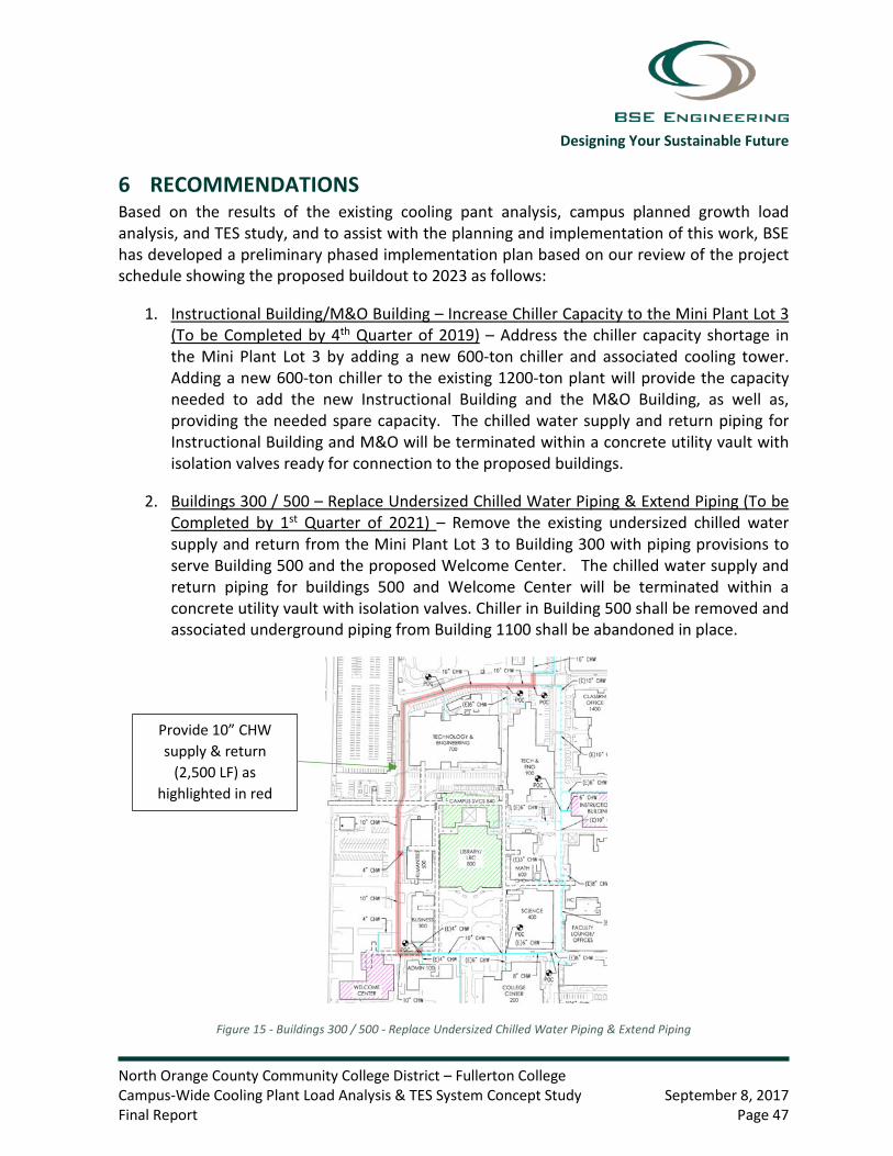
Designing Your Sustainable Future
North Orange County Community College District – Fullerton College Campus-Wide Cooling Plant Load Analysis & TES System Concept Study September 8, 2017 Final Report Page 47
6 RECOMMENDATIONS Based on the results of the existing cooling pant analysis, campus planned growth load analysis, and TES study, and to assist with the planning and implementation of this work, BSE has developed a preliminary phased implementation plan based on our review of the project schedule showing the proposed buildout to 2023 as follows:
1. Instructional Building/M&O Building – Increase Chiller Capacity to the Mini Plant Lot 3 (To be Completed by 4th Quarter of 2019) – Address the chiller capacity shortage in the Mini Plant Lot 3 by adding a new 600-ton chiller and associated cooling tower. Adding a new 600-ton chiller to the existing 1200-ton plant will provide the capacity needed to add the new Instructional Building and the M&O Building, as well as, providing the needed spare capacity. The chilled water supply and return piping for Instructional Building and M&O will be terminated within a concrete utility vault with isolation valves ready for connection to the proposed buildings.
2. Buildings 300 / 500 – Replace Undersized Chilled Water Piping & Extend Piping (To be Completed by 1st Quarter of 2021) – Remove the existing undersized chilled water supply and return from the Mini Plant Lot 3 to Building 300 with piping provisions to serve Building 500 and the proposed Welcome Center. The chilled water supply and return piping for buildings 500 and Welcome Center will be terminated within a concrete utility vault with isolation valves. Chiller in Building 500 shall be removed and associated underground piping from Building 1100 shall be abandoned in place.
Figure 15 - Buildings 300 / 500 - Replace Undersized Chilled Water Piping & Extend Piping
Provide 10” CHW supply & return
(2,500 LF) as highlighted in red

Designing Your Sustainable Future
North Orange County Community College District – Fullerton College Campus-Wide Cooling Plant Load Analysis & TES System Concept Study September 8, 2017 Final Report Page 48
3. TES & Chilled Water Piping Loop (Upon Approved Funding) – Implement the recommendations of Concept 2 by extending the chilled water piping to the Fine Arts Building, therefore completing the campus chilled water loop, and installing the recommended 932,000 gallon (70’-5” ID x 32’-0” water depth) tank. The chilled water supply and return piping for the proposed Performing Arts Building and existing Wilshire Buildings will be terminated within a concrete utility vault with isolation valves ready for extension.
Figure 16 - TES & Chilled Water Piping Loop
4. Wilshire Buildings (6 Months Prior to Construction of New Buildings) – Extend the chilled water piping from the main campus to the Wilshire Buildings to serve the new Performing Arts Complex, including the second Instructional Building and all other existing buildings. Additional architectural studies will have to be completed in order to determine the best way to route the chilled water piping across Chapman Ave.
Figure 17 - Wilshire Buildings
Install 8” CHW supply & return
(2,500 LF) highlighted in red
Install 10” CHW supply & return
completing CHW loop (1,000 LF)
highlighted in red

Designing Your Sustainable Future
North Orange County Community College District – Fullerton College Campus-Wide Cooling Plant Load Analysis & TES System Concept Study September 8, 2017 Final Report Page 49
The recommended TES Concept 2 assumes a central plant delta T of 22-degrees. The existing “Mini Plant” Lot 3 central plant is designed at a 12-degree delta T. In order for the new central plant and TES system to operate most efficiently, the existing chilled water coils at each existing building will need to be replaced with new coils that are designed at a minimum 20-degree delta T. Increasing the delta T at the existing buildings will also reduce the chilled water flow, which will help eliminate choke points in the chilled water loop. For example, the 10” main chilled water pipe identified at point A on Table 12 can be eliminated if the cooling coils at existing buildings 200, 600, 1000, 1200, and 1400 are replaced with coils designed at higher delta T’s. For the purposes of this study and associated pricing scope, we have assumed that the recommended coil replacements to improve the flow rates and therefore maintain the existing 10” chilled water pipes will be adopted. However, if the coil replacements do not take place the existing 10” underground pipes will need to be replaced with 12” pipes.
Figure 18 - Point A Chilled Water Pipe Choke Point
As identified in Figure 18 above, the (E)10” CHW piping from the central plant to building 1400 may need replacement if flow rate improvements are not adopted as recommended in this study. This report recommend replacement of all old existing cooling coils to avoid the need to replace the additional 900 linear feet of chilled water piping (450 LF of trench).
May need to replace coiling coils or replace (E)10” CHW with 12”
CHW (900 LF) as

Designing Your Sustainable Future
North Orange County Community College District – Fullerton College Campus-Wide Cooling Plant Load Analysis & TES System Concept Study September 8, 2017 Final Report Page 50
Appendix A – CHW Analysis

Designing Your Sustainable Future
North Orange County Community College District – Fullerton College Campus-Wide Cooling Plant Load Analysis & TES System Concept Study September 8, 2017 Final Report Page 51
Appendix B - Photos

Designing Your Sustainable Future
North Orange County Community College District – Fullerton College Campus-Wide Cooling Plant Load Analysis & TES System Concept Study September 8, 2017 Final Report Page 52
Photo 1 – Lot 3 Cooling Towers
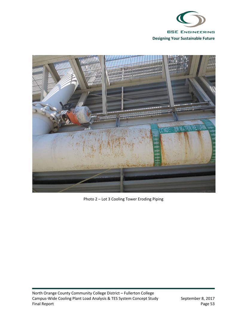
Designing Your Sustainable Future
North Orange County Community College District – Fullerton College Campus-Wide Cooling Plant Load Analysis & TES System Concept Study September 8, 2017 Final Report Page 53
Photo 2 – Lot 3 Cooling Tower Eroding Piping

Designing Your Sustainable Future
North Orange County Community College District – Fullerton College Campus-Wide Cooling Plant Load Analysis & TES System Concept Study September 8, 2017 Final Report Page 54
Photo 3 – Lot 3 Chiller 2 Leak

Designing Your Sustainable Future
North Orange County Community College District – Fullerton College Campus-Wide Cooling Plant Load Analysis & TES System Concept Study September 8, 2017 Final Report Page 55
Photo 4 – Chiller #1100-2 Cracking Casing

Designing Your Sustainable Future
North Orange County Community College District – Fullerton College Campus-Wide Cooling Plant Load Analysis & TES System Concept Study September 8, 2017 Final Report Page 56
Photo 5 – Chiller #500 BTU Meter Not Functioning Properly

Designing Your Sustainable Future
North Orange County Community College District – Fullerton College Campus-Wide Cooling Plant Load Analysis & TES System Concept Study September 8, 2017 Final Report Page 57
Photo 6 – Chiller #2100 Cracking Casing

Designing Your Sustainable Future
North Orange County Community College District – Fullerton College Campus-Wide Cooling Plant Load Analysis & TES System Concept Study September 8, 2017 Final Report Page 58
Photo 7 – Chiller #2100 Insulation

Designing Your Sustainable Future
North Orange County Community College District – Fullerton College Campus-Wide Cooling Plant Load Analysis & TES System Concept Study September 8, 2017 Final Report Page 59
Photo 8 – Pumps PP 2100-1, PP 2100-2, SP 2100-1, and SP 2100-2

Designing Your Sustainable Future
North Orange County Community College District – Fullerton College Campus-Wide Cooling Plant Load Analysis & TES System Concept Study September 8, 2017 Final Report Page 60
Photo 9 – Plant 2100 Cooling Towers

Designing Your Sustainable Future
North Orange County Community College District – Fullerton College Campus-Wide Cooling Plant Load Analysis & TES System Concept Study September 8, 2017 Final Report Page 61
Photo 10 – Chiller #2100 Leak

Designing Your Sustainable Future
North Orange County Community College District – Fullerton College Campus-Wide Cooling Plant Load Analysis & TES System Concept Study September 8, 2017 Final Report Page 62
Appendix C – Utility Rates

Designing Your Sustainable Future
North Orange County Community College District – Fullerton College Campus-Wide Cooling Plant Load Analysis & TES System Concept Study September 8, 2017 Final Report Page 63

Designing Your Sustainable Future
North Orange County Community College District – Fullerton College Campus-Wide Cooling Plant Load Analysis & TES System Concept Study September 8, 2017 Final Report Page 64

July 14, 2017 Mr. Philip Metzger, E.I.T. Design Engineer BSE Engineering, Inc. [email protected] Reference: REVISED Budgetary Proposal – Thermal Energy Storage Tank
Fullerton College – Fullerton, CA Dear Philip: Per your request, we are pleased to provide this REVISED budgetary proposal for the design and construction of concrete Thermal Energy Storage (TES) tank options for Fullerton College in Fullerton, CA. This proposal includes our watertight and maintenance-free prestressed concrete TES tank designed and built in accordance with AWWA-D110 Standard. The TES tank options will be designed based on the following performance criteria and dimensional details:
Option #1 – Full Storage (On-Peak and Mid-Peak) TES Tank: Useable TES Capacity 19,647 ton-hrs Chilled Water ∆T 18.0°F Maximum CHW Flow Rate 5,241 gpm (calculated assuming 5 hr discharge) Maximum Chilled Water Pressure Drop 3 psi total or less thru tank Maximum Allowable Heat Gain 2% in 24 hours Total Volume 1,747,000 gal
Tank Dimensions 96’-5” ID x 32’-0” water depth Freeboard 4’-3” Floor Design 6” thick flat concrete membrane
Roof Design Free span concrete dome Required Soil Bearing Capacity 2,800 psf (approximate) Option #2 – Full Storage (On-Peak) TES Tank: Useable TES Capacity 10,481 ton-hrs Chilled Water ∆T 18.0°F Maximum CHW Flow Rate 2,796 gpm (calculated assuming 5 hr discharge) Maximum Chilled Water Pressure Drop 3 psi total or less thru tank Maximum Allowable Heat Gain 2% in 24 hours Total Volume 932,000 gal
Tank Dimensions 70’-5” ID x 32’-0” water depth Freeboard 4’-3” Floor Design 6” thick flat concrete membrane
Roof Design Free span concrete dome Required Soil Bearing Capacity 2,800 psf (approximate)

Page 2 of 4
Option #3 – Partial Storage TES Tank: Useable TES Capacity 6,908 ton-hrs Chilled Water ∆T 18.0°F Maximum CHW Flow Rate 1,843 gpm (calculated assuming 5 hr discharge) Maximum Chilled Water Pressure Drop 3 psi total or less thru tank Maximum Allowable Heat Gain 2% in 24 hours Total Volume 615,000 gal
Tank Dimensions 59’-1” ID x 30’-0” water depth Freeboard 4’-3” Floor Design 6” thick flat concrete membrane
Roof Design Free span concrete dome Required Soil Bearing Capacity 2,700 psf (approximate)
This proposal includes the design and construction of a prestressed concrete TES tank built above grade, with a minimum 6” thick concrete membrane floor, and a free span concrete dome roof. The integrity of the tank will meet the design load conditions for this project, ambient design conditions, and seismic conditions for this region. The TES tank will be equipped with the following appurtenances:
• One oversized aluminum lockable rain-proof personnel access roof hatch • One interior fiberglass ladder with OSHA fall prevention devices • Two chilled water inlet & outlet wall nozzles • Schedule 40 PVC slotted octagonal diffuser piping, or FRP plate diffuser • Two 6” dia. 304 SS roof nozzles for mounting the temperature and level sensors, by others • One 6” dia. perforated PVC pipe mounted vertically and directly below the temperature sensor
nozzle as listed above. • One DICL overflow wall nozzle and roof vent • EIFS exterior wall insulation system with cementitious coating
This budgetary proposal includes an “allowance” for the site preparation work. At this time, we do not have a geotechnical report for the tank site or tank type. For this proposal, we have made the following assumptions regarding the sitework and foundation:
• Groundwater will be below the bottom of the tank floor • Existing overhead and underground utilities will be relocated by others • The tank will be supported on a shallow foundation • The total settlement and differential settlement of the tank will be within tolerable limits • No hazardous materials in the soils at the tank site
Typical site preparation would include at a minimum the following scope of work for a TES tank with a shallow foundation system:
• Erosion control & barricades • Excavation of the soils to an approved subgrade elevation per the geotechnical engineer • Development and stabilization of a temporary access road and crane positions • Hauling and temporary stockpile of soils on campus for backfill during site restoration • Development & stabilization of a temporary 10’ wide work track around the perimeter of the tank
floor foundation • Temporary dewatering during construction, as required • Structural fill and leveling base material from the top of the excavation to the bottom of the tank
floor per the recommendations of the geotechnical engineer • Woven geotextile fabric, as required • Backfill of soils and site restoration

Page 3 of 4
Exclusions: This proposal does not include: geotechnical report, hazardous waste removal, instrumentation, any yard piping or mechanical equipment outside of the tank, deep pile foundation (if required), water, chemicals, bonds, sales tax, or special permits. Preliminary Design and Construction Schedule: After receipt of the notice to proceed and the geotechnical report, the design for the tank will take 6 weeks. After the design is approved and the site preparation is complete, the tank construction will take approximately 5 and 6 months (depending on the Option selected) from mobilization to ready for filling with water. There are no long lead materials required for this project. Work weeks include 5 days x 8 hours. Construction of the tank is assumed to begin in 2018. Warranty: DN Tanks will warranty the structural integrity, leak-free performance of the tank for two years from the substantial completion date. The expected useful life of this tank is well over 50 years. Budgetary Pricing: Option #1 – Full Storage (On-Peak and Mid-Peak) TES Tank:
Design & Construction of One 1.747 MG TES Tanks w/Appurtenances: $ 2,355,000 Site Preparation Allowance: $ 350,000
Total Budgetary Estimate: $ 2,705,000 Alt-Add – Faux Brick Façade on the Exterior Walls: $ 110,000
Alt-Add – Tri-color Logo of the University: $ 15,000
Option #2 – Full Storage (On-Peak) TES Tank: Design & Construction of One 0.932 MG TES Tanks w/Appurtenances: $ 1,707,000
Site Preparation Allowance: $ 250,000 Total Budgetary Estimate: $ 1,957,000
Alt-Add – Faux Brick Façade on the Exterior Walls: $ 80,000
Alt-Add – Tri-color Logo of the University: $ 15,000 Option #3 – Partial Storage TES Tank: Design & Construction of One 0.615 MG TES Tanks w/Appurtenances: $ 1,428,000
Site Preparation Allowance: $ 200,000 Total Budgetary Estimate: $ 1,628,000 Alt-Add – Faux Brick Façade on the Exterior Walls: $ 65,000
Alt-Add – Tri-color Logo of the University: $ 15,000

Page 4 of 4
This budgetary pricing will remain valid for (90) days. This pricing assumes that we can mobilize for tank construction in 2018 and build the tank without interruption utilizing union labor. Benefits of a Prestressed Concrete TES Tank o Site Flexibility – A concrete tank can be constructed above ground, partially or fully buried without
requiring special retaining walls as necessary with a steel tank. o No Maintenance – Because it is constructed of concrete, the tank will never require re-painting of
the interior surfaces which may be necessary with a steel TES tank.
o Architectural Enhancements – a concrete tank with EIFS insulation allows for many economical architectural enhancement features.
o Superior Construction – The concrete walls and roof of our tank are cast on site and inspected under
strict guidelines to ensure the leak-free integrity. o No Downtime – Our concrete tank does not require maintenance and is built to a watertight (zero
measurable loss) tolerance, the tank will provide 100% reliability for the owner. o Investment in the Local Economy – over 50% of the cost to construct our tank is from local suppliers
and local labor. o Short Construction Cycle – There are no long lead items in the construction of our tank. Please call me if you have any questions regarding this REVISED budgetary proposal. Thank you for the opportunity to work with you and the BSE Engineering team on this project for Fullerton College in Fullerton, CA. Respectfully submitted,
Guy Frankenfield Energy Division Manager DN TANKS | Generations Strong 410 E. Trinity Blvd., Grand Prairie, TX 75050 Main Office 972.823.3300 | Cell 214.755.4610 | Fax 972.823.3333 www.DNTanks.com

Energy EfficiencyOn Demand
ThErmal EnErgy STOragE TankS

Thermal energy STorage (TeS) is a proven component of district energy company strategies. For 30 years, Dn Tanks has designed and built pre-stressed concrete tanks — throughout the world — for storing the chilled water integral to the Thermal energy Storage process. every single one of these tanks is watertight and operational today.
By producing chilled water during off-peak hours, and then utilizing the stored water during peak periods, the peak electrical load is permanently reduced. This lowers energy cost by reducing peak electric demand and energy consumption, saving owners thousands of dollars each year. For expansion projects, owners can avoid the capital cost of adding a chiller by instead utilizing a TeS tank.
A Thermal Energy Storage tank integrates seamlessly into any chilled water district cooling system. Because of the specially designed internal diffuser system, the chilled water remains stratified within the tank throughout the charging and discharging process.
Why and when it’s used
How TES workS
WiThouT TeS WiTh TeS

Flexible, cost-effective and customizable
owners rely on TES to reduce energy costs and increase efficiency
Dn Tanks constructs pre-stressed concrete tanks for Thermal energy Storage. Typical owners include: airports, schools and universities, hospitals, government and military bases, power plants and private industries. TeS is also used as a backup for chilled water systems that require 24/7 cooling — such as mission critical data centers.
loWeST liFe cycle coST (no repainTing The inTerior)
WaTerTighT & mainTenance-Free
parTially or Fully BurieD
SigniFicanT inveSTmenT in The local economy
numerouS archiTecTural enhancemenTS
no long leaD maTerialS
hospitals & airports Danville, pa41.07 mg TeS Tank
government & military lackland aFB40.80 mg TeS Tank
power plantscleburne, TX41.74 mg TeS Tank
DID yOU knOW?
industrial & commercial Brooks, ca41.37 mg TeS Tank
Data centers ashburn, va4(3) 0.50 mg TeS Tanks
Schools & universitiesorlando, Fl43.00 mg TeS Tank
a kilowatt-hour of electricity used to charge a TeS tank at night can be produced at a much lower cost than one produced during the day.
TeS tanks are compatible with any large, chilled water cooling system.
TeS is the most cost-effective method to store energy produced by unpredictable renewable power generation sources like wind and solar.
The electric grid is more reliable due to cost- effective energy storage systems like TeS.

Numerous architectural enhancements
The exterior of a Dn Tanks pre-stressed concrete TeS tank can be customized to blend in with its environment, match the surrounding buildings, or become an iconic landmark.
The right decision for all the right reasons
visit our website to view project profiles of our TeS tanks. if you have any questions, or would like to discuss your TeS system, visit our website at www.DnTanksTeS.com or contact us at 800.837.6133.
Maximum Storage Capacity: Dn Tanks’ specially designed diffuser minimizes turbulence and creates a stable thermocline — ensuring a separation between the incoming warm water and chilled water. This narrow thermocline is key to optimizing the tank’s capacity and efficiency.
Unparalleled Reliability: Dn Tanks’ pre-stressed concrete tanks perform reliably for decades. in fact, every one of the TeS tanks we’ve ever built is still in service today.
Lower Cost of Ownership: a Dn Tanks pre-stressed concrete tank will last for generations — with no scheduled maintenance. This makes it a superior choice for long-term value and cost of ownership.
Construction Flexibility: Because of inherent characteristics of concrete, the TeS tank can be partially or fully buried underground.
Custom Logo
Faux Brick
Partially or Fully Buried
Customized Finish
Matches Buildings
AdvANTAgE: dN TANkS

“Throughout the entire construction and commissioning phases, we were very happy with DN Tanks. They met all of our required schedule dates while upholding very high safety precautions due to the close proximity of the TES tank to plant equipment and personnel.” — JOE STUPARICH, TAS ENERGY
www.DnTankSTES.com

about Dn Tanks Dn Tanks designs and constructs pre-stressed concrete liquid storage tanks. The hallmarks of our work are long-term performance, durability, reliability, no scheduled maintenance requirements, and lowest cost of ownership.
although we have constructed literally thousands of tanks, the ultimate measure of our success is our commitment to quality and safety while providing the absolute best service to our customers.
DnTankS.COm
Wakefield Facility11 Teal road Wakefield, ma 01880p: 781.246.1133
grand prairie Facility410 east Trinity Blvd. grand prairie, TX 75050p: 972.823.3300
el cajon Facility351 cypress lane el cajon, ca 92020p: 619.440.8181
middle east officesumm ghuwaillina, c-ring roadal hitmi Building #7, 1st Floor office #6p.o. Box 15619Doha, Qatarp: +974 5553.0136
operaTionS FaciliTieS
cover photo:
Salt Lake city, Ut3.42 MG teS tank
back cover photo:
bakersfield, ca0.68 MG teS tank
inSide pocket photo:
orlando, FL3.00 MG teS tank
inSide LeFt photo:
raleigh, nc 2.68 MG teS tank


CONSTRUCTION
PROCEDURES
AWWA D110 Type I Prestressed Concrete Tanks

Site Preparation | Floor & Footings
Wall Construction
Roof Options
Vertical Prestressing | Abrasive Blasting
Circumferential Prestressing | Advanced Technology
Automated Shotcrete | Appurtenances
Tank Rendering
Tank Gallery
2 - 3
4 - 5
6 - 7
8 - 9
10 - 11
12 - 13
14 - 15
16 - 17

At DN Tanks, we understand that a liquid storage tank is a critical component of infrastructure that serves a variety
of storage needs, such as a community’s potable water source, fire suppression source, an important step in the
treatment of wastewater, a consistent source of recycled water, as well as many other uses. Each of these tanks
are instrumental to the communities they serve.
DN Tanks’ prestressed concrete storage tanks are individually designed with a full structural analysis to meet
specific project needs. Quality, durability, and efficiency are ensured through specially trained and skilled field
crews, advanced prestressing technology, and professional project management.
Over 50 years of experience are ingrained into each AWWA D110 Type I prestressed concrete tank. Our years
of commitment and focus in the prestressed concrete tank industry have cultivated expertise in engineering,
estimating, project management, and construction. From project development and design assistance to
construction and prestressing, DN Tanks’ dedicated team is ready to provide support services to ensure a
successful tank project. We measure success by our lasting partnerships with clients and communities.
KEY ATTRIBUTES OF DN TANKS’ AWWA D110 TYPE I PRESTRESSED CONCRETE TANKS
• Tank Capacities - from 40,000 gallons to 50 million gallons (MG) and above
• Custom Dimensions - water heights from 8’ to over 100’ and diameters from 25’ to over 400’
• Siting Options - at grade, partially buried, differentially backfilled (hillsides), fully buried (with multi-use capabilities)
• Seismic Resilience - proven performance through Loma Prieta, Nisqually and Northridge earthquakes to name a few
• Enhanced Ductility - anchored flexible base and roof connections
• Bi-axial Wall Compression - provides longevity, durability and liquid tightness
• Best Long-term Value - coatings aren’t required thus eliminating routine maintenance costs and down-time burdens
• Reinvesting in the Local Economy - use of materials, labor and equipment from within the community
• Enhanced Water Quality - concrete inherently insulates, keeping liquids at a more consistent temperature
DURABILITY FOR GENERATIONS TO COME
1

SITE PREPARATION
A properly prepared subgrade is essential to tank construction.
Before the structural tank design begins, a licensed geotechnical
engineer prepares a site specific geotechnical report. The report
provides design parameters that include bearing capacity,
anticipated settlements, seismic criteria, and recommended
subgrade and foundation preparation.
• Subgrade preparation for each tank is completed in
accordance with the civil site plans and the site specific
geotechnical report
• Piping connections that penetrate through the floor
(e.g. inlet, outlet, overflow, etc.) are encased in
underslab concrete pipe blocks
• A waterstop is incorporated between the floor and pipe block
to ensure a liquid tight connection
• Wall and roof pipe penetrations can be easily incorporated
2

• A cast-in-place, highly-reinforced, concrete membrane
floor with a slight upward slope to the center allows
for drainage
• Monolithic or large section pours limit joints to improve
tank performance and achieve construction efficiency
• A thickened perimeter wall footing to transmit the
concentrated wall loads to the subgrade beneath
• A permanent PVC waterstop at all joints for
water tightness
• Seismic base restraint cables are developed into
the perimeter footing to account for site specific
seismic loading
• Structural observation is performed by a Registered
Engineer prior to the concrete pour
• Experienced field crews place the concrete and ensure
it is vibrated, screeded, and finished to meet the
project specifications
FLOOR & FOOTINGS
A typical prestressed concrete tank floor consists of the following features:
3

CAST-IN-PLACE WALL CONSTRUCTION
Prestressed concrete places steel in tension and concrete in compression,
allowing for both materials to resist forces in their ideal states. The corewall
is designed to account for project specific parameters and loadings. A typical
tank corewall consists of a 10” minimum uniform thickness. For larger capacity
tanks, walls may be thicker and tapered on the inside face to accommodate
increased loads.
FEATURES OF AN AWWA D110 TYPE I WALL
Enhanced Operational and Seismic Performance
• “Anchored flexible base” connection between the floor and wall (similar to a
base isolation system) enhances ductility and reduces bending moments from
hydrostatic, thermal, and seismic forces, allowing these structural elements
to act independently
• Seismic base restraint cables anchored into the footing extend into the
corewall, providing load transfer during a seismic event
Quality Control
• Circumferential wall forms curved to the specific tank radius are equipped
with equally spaced pour windows to enhance quality control, reduce overall
drop height, and allow ease of access for concrete placement and vibration
• Walls are poured full height in up to 50’ wide circumferential sections
• Rebar congestion is significantly reduced, promoting more efficient inspection
and concrete placement
Liquid Tightness and Durability
• Vertical prestressing threadbars cast in the wall provide vertical compression
and minimize vertical bending moments caused by differential temperature
and dryness conditions
• Horizontal joints are eliminated and vertical joints are minimized to provide
superior water tightness
• All construction joints incorporate permanent PVC waterstops
4

5

6

ROOF OPTIONS
Prestressed concrete tanks can be designed
with a variety of roof options.
FLAT ROOF FEATURES
• Low profile cast-in-place, two-way flat slab roof
minimizes visibility
• Option to bury or accommodate multi-use
structures such as parks, recreation facilities,
pump stations, etc. on the tank roof
• An anchored flexible wall/roof connection allows
for thermal expansion of the roof slab while also
providing seismic restraint
• Evenly spaced concrete columns, designed with
drop panels and footings, support the roof and
transfer the corresponding loads
• A slight upward slope to the center, matching the
floor, provides drainage
DOME ROOF FEATURES
• A clear-spanning concrete dome with no interior
supports or obstructions can easily accomodate
various equipment needs
• Typical dome height is 10% of the tank diameter
• Continuous reinforcement is incorporated in
both radial and circumferential directions
• Circumferential prestressing applied at the dome
ring places the dome in permanent compression
7

VERTICAL PRESTRESSING
AWWA D110 Type I tanks incorporate vertical
prestressing threadbars within the wall to provide
vertical compression and counteract bending.
Features include:
• High-strength steel threadbars are either
1 ¼” or 1 ¾” diameter depending on
corewall thickness
• Threadbars are equipped with a screwed-on
nut anchor at the top and bottom to eliminate
stress concentrations
• Each threadbar is housed inside of a rigid
PVC pipe to allow for proper installation
• A hydraulic ram is used to tension the
threadbars after the concrete walls are poured
• Threadbars are tensioned to 137 kips or
173 kips for the respective diameter, with a
tight force tolerance of 1.5%
• Force and elongation recordings are
electronically and instantaneously produced
for each vertical threadbar, documenting the
applied stress
• After tensioning, threadbars are pressure
grouted from the bottom up with a two-part
epoxy to achieve a fully bonded system and
corrosion protection
8

ABRASIVE BLASTING
Prior to starting circumferential prestressing and shotcrete operations, DN Tanks’ advanced
abrasive blasting system roughens the exterior corewall surface. System features include:
• Automated hydroblasting applies water at a high pressure of up to 40,000 psi to etch the
wall to a precise roughened finish, providing a superior bonding surface
• An automated system reduces jobsite hazards, optimizes construction schedule and
provides a consistent finish
• Hydroblasting is environmentally friendly as it requires very low water usage and
eliminates dust
9

CIRCUMFERENTIAL PRESTRESSING
Circumferential prestressing is the heart of the
tank structure, counteracting the liquid load and
placing the tank wall in 200 psi residual compression.
DN Tanks’ significant industry advancements includes
the automated machine application of tensioned,
hot-dip galvanized, ” diameter 7-wire strand.
By placing the strand in tension, and thereby the
concrete wall in compression, the prestressed
concrete tank incorporates both materials in
their ideal states.
The mechanical prestressing system allows
application of a consistent prestressing force of
14,950 pounds with a tight tolerance of 1.5%
of MUS. This greatly exceeds the AWWA minimum
standard accuracy of 7% of the applied force.
Strand is tensioned to 70% of MUS, placing the
wall in permanent bi-axial compression to withstand
the varying operational hydrostatic loads, as well as
thermal and seismic dynamic loads.
BENEFITS OF STRAND-WRAPPING:
• Improved accuracy & efficiency
• Tighter force tolerance
• Electronic spacing & recording
• Fewer splices
• Increased shotcrete bond
• Greater safety factor
10

ELECTRONIC MONITORING & CONTINUOUS RECORDING
Continuous electronic recording and
instantaneous self-correcting force application
are essential to ensure the proper stress
is applied to the prestressing steel. The
prestressing steel places the concrete into
permanent compression and resists all
hydrostatic loads. It is imperative that the
stress is applied accurately. The automated
system offers:
• Computerized, continuous electronic force
readings for the highest quality control
• In-line calibration allowing for instantaneous
control of the force applied
• A record of the force readings submitted
to the Owner, providing confidence that
the most critical part of the hydrostatic
resistance has correctly been applied
ADVANCED TECHNOLOGY
DN Tanks’ state-of-the-art circumferential
prestressing equipment is able to perform
multiple sophisticated tasks with one simple,
automated, quality-controlled unit. In-line
calibration and stress monitoring are utilized
to provide complete accuracy in every step
of the process.
11

AUTOMATED SHOTCRETE
The advanced technology of the automated shotcrete process is
proven to preserve the integrity of DN Tanks’ structures by providing
corrosion protection and a permanent bond.
FEATURES OF AUTOMATED SHOTCRETE
• Control of numerous variables such as uniform distance, angle,
and applied thickness on large surface areas ensure complete
encapsulation of the prestressing strand as well as a proper bond
to the corewall
• Wet-mix shotcrete applied from a nozzle mounted on a
mechanized tower travels at a controlled uniform speed and path
• A minimum final shotcrete cover of 1.5 inches, built up
in multiple layers
12

APPURTENANCES
Prestressed concrete tanks can accommodate a variety
of accessories, such as roof and wall access hatches,
interior and exterior ladders, vents, safety railings, level
sensing equipment, or specialized security hardware.
Our experienced team can help recommend and install
appurtenances to meet specific project requirements.
13

10
11
12
7
6
3
2
1
5
8
94
1 PVC Waterstop
2 Elastomeric Wall-Base Bearing Pad
3 Tank Foundation
4 Vertical Prestressing Threadbars Housed in PVC Pipe
5 Cast-in-Place Concrete Corewall
6 Seismic Base Restraint Cables
7 Continuous Circumferential Reinforcing
8 ” Ø 7-Wire Galvanized Circumferential Prestressing Strand
9 Shotcrete Encasement
10 Roof Shear Can
11 Wall Shear Can
12 Elastomeric Wall-Top Bearing Pad
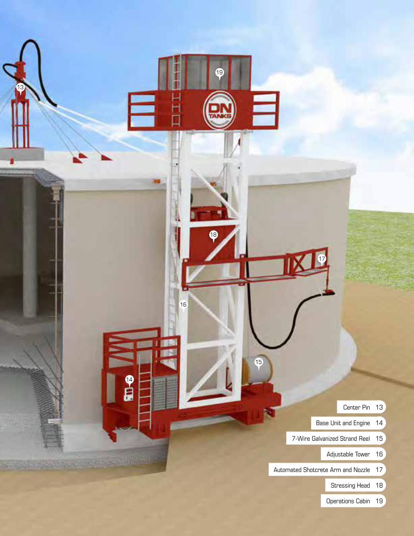
13 Center Pin
14 Base Unit and Engine
15 7-Wire Galvanized Strand Reel
16 Adjustable Tower
17 Automated Shotcrete Arm and Nozzle
18 Stressing Head
19 Operations Cabin
19
18
17
16
15
14
13

DN TANKS SHOWCASE


Generations Strong
351 Cypress Lane • El Cajon, CA 92020 • 800.227.8181 • www.dntanks.com