campus area networking technologies for routing packets from one lan to another
TRANSCRIPT

Campus Area Networking
Technologies for routing packets from one LAN to another

Layer 3 Communication
R
S
R
S
SS

Network - Layer 3
The network layer establishes the route between the sending and receiving stations. The node to node function of the data link layer (layer 2) is extended across the entire internetwork, because a routable protocol contains a network address in addition to a host address.

Application
Presentation
Session
Transport
Network
Data Link
Physical
©”A Guide to Networking Essentials”, 1998, Course Technology.
OSI Reference Model

Routing
BODY
Layer 3Header
Layer 2Trailer
Layer 2Trailer
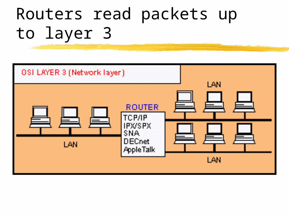
Routers read packets up to layer 3

Network Routing
Protocols for internetworking.

Two major types
Packet switching (or datagram) Usually layers 3 and 4
Circuit switching Usually layers 1 and/or 2

Packet switching or Datagram Protocols
Best effortFrames take individual routesPacket assembly devices neededError ControlTraffic Management
Buffering Discard
Node Functions
Message forwardingError detection and correctionTraffic management

Router Functions
Routers perform layer 1, 2, and 3 functions Packet passing
Error correction
Message routingIncluding circuit definition
Protocol translation Firewall functions(see the tracert function on the TCP/IP stack)
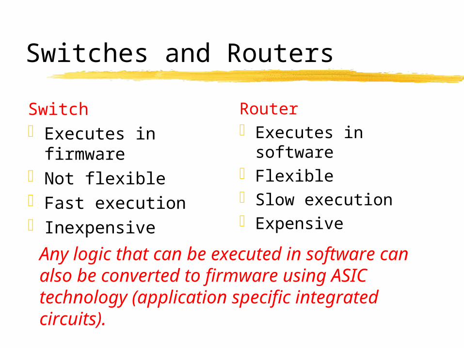
Switches and Routers
SwitchExecutes in
firmwareNot flexibleFast executionInexpensive
RouterExecutes in softwareFlexibleSlow executionExpensive
Any logic that can be executed in software can also be converted to firmware using ASIC technology (application specific integrated circuits).

Routers
Input Buffer
ProcessorOutput Buffer
From A From B
To C To D
Table ofAddresses
Input Buffer
Input BufferOutput Buffer

Packet Routing
Datagram Packets proceed along their own route
and must be reordered at the end.Circuit
Packets all take the same route and arrive in order

Datagram Logic (IP)
Packet n Packet 1Packet 2
32
1
31
2
32
1
PAD

IP
Best EffortAddressingVariable packet lengths (1500 bytes
or less)IPv4 vs IPv6Frame and Header

The Internet:IP Addressing – IP v4
32 bits (4 bytes) Network address + Host address in one
Classes (originally) A: 126 nets, 3 bytes of client
addresses B: 2 bytes of client addresses (e.g. OU) C: 1 byte of client addresses (256)
Next step – IPv6 128 bit address space Why?

IP Header (Layer 3)
Version =4
Header length In bytes
Type of service Characteristic of route
Total length Length of the packet
Source port identifier Port identifier for host process
Fragment offset Position (8 byte units) from message start
Time to live Allowed seconds
Protocol ID of Transport layer protocol (TCP = 6)
Header checksum
Source address 32 bits
Destination address 32 bits
Options + Padding
Data

How IP Routing Works


IPRouting
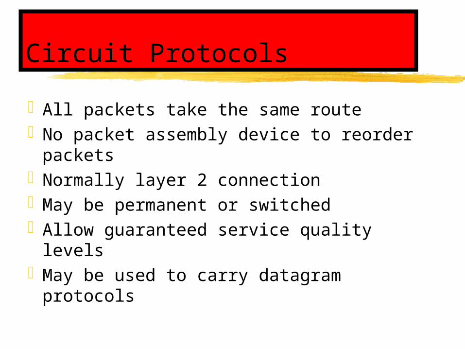
Circuit Protocols
All packets take the same routeNo packet assembly device to reorder
packetsNormally layer 2 connectionMay be permanent or switchedAllow guaranteed service quality levelsMay be used to carry datagram
protocols

Circuit Logic
Source Destination
Setup
Message & ACK’s
Teardown

Frame Relay
Frames relayed without reconstruction
End to end error control using CRC error detection at layer 3 level
Variable packet sizeVirtual circuit (usually permanent)Multiple data ratesMultiple quality levels
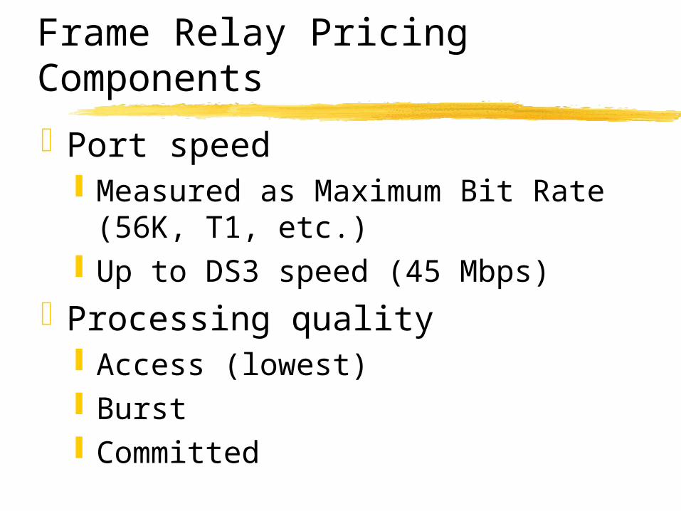
Frame Relay Pricing Components
Port speed Measured as Maximum Bit Rate
(56K, T1, etc.) Up to DS3 speed (45 Mbps)
Processing quality Access (lowest) Burst Committed

Frame Relay Processing Quality

Asynchronous Transfer Mode – layer 2 networking
Cell switchedEqual length cells – 53 bytes
Like machine gun bulletsFast: Speeds up to 9953 MbpsSupports Quality of Service classesUsed primarily as a backbone
technology

ATM Cell Format
Frame segment Size
Generic Flow Control Virtual Circuit (notused)
4 bit
Virtual Path Identifier 1 byte
Virtual Channel Identifier 2 bytesPayload Type Identifier 3 bitCell Loss Priority 1 = discard eligible 1 bitHeader Error CorrectionData 48 bytes

ATM Traffic Classes (QoS)
Constant Bit Rate (CBR) Real time voice & video
Variable Bit Rate – real time (rt-VBR)
Compressed video & LAN
Variable Bit Rate – non real time (nrt-VBR)
LAN internetworking
Available Bit Rate (ABR) Non mission critical bursty Traffic
Unspecified Bit Rate (UBR)
No guarantee, e-mail, bulk file transfers
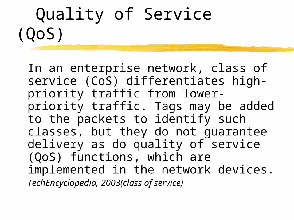
Class of Service CoS) and Quality of Service (QoS)
In an enterprise network, class of service (CoS) differentiates high-priority traffic from lower-priority traffic. Tags may be added to the packets to identify such classes, but they do not guarantee delivery as do quality of service (QoS) functions, which are implemented in the network devices.
TechEncyclopedia, 2003(class of service)
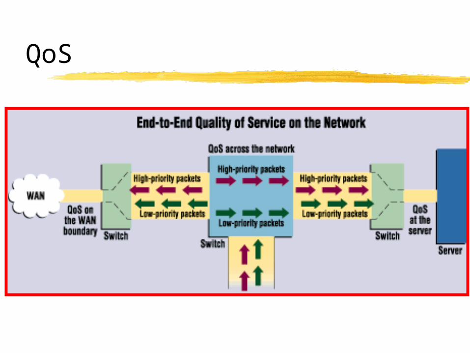
QoS
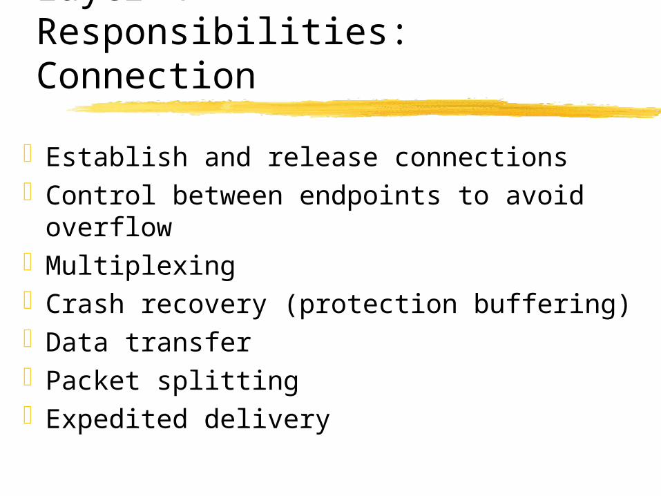
Layer 4 Responsibilities:Connection
Establish and release connectionsControl between endpoints to avoid
overflowMultiplexingCrash recovery (protection buffering)Data transferPacket splittingExpedited delivery

Transport - Layer 4
The transport layer is responsible for overall end to end validity and integrity of the transmission. The lower data link layer (layer 2) is only responsible for delivering packets from one node to another. Thus, if a packet gets lost in a router somewhere in the enterprise internet, the transport layer will detect that. It ensures that if a 12MB file is sent, the full 12MB is received.

TCP and UDP
Transmission Control Protocol
Connection oriented
Assures that packets arrive in order and that they are correct.
User Datagram Protocol
Connectionless
Sends packets out without confirming that they arrive

TCP Header (layer 4)
Source port (16 bits) Ports of communicating processes
Destination port (16 bits) “
Sequence Number (32 bits) Location of current fragment inmessage
Acknowledgement Number (32 bits) Number of frame to beacknowledged next
Offset Number of 32 bit words in header
Reserved Not used
Flags
Window Number of frames sender canaccept without buffer overflow
Checksum (16 bits)
Urgent Pointer

Ethernet/TCP/IP Header Structure

UDP Routing

Layer 5 Responsibilities
Dialog managementSynchronization of checkpoints for
error recoveryActivity management to assure
complete action messages

Session - Layer 5
Coordinates communications. Determines one-way or two-way communications and manages the dialogue between both parties; for example, making sure that the previous request has been fulfilled before the next one is sent. It also marks transmitted data with checkpoints to allow for fast recovery in the event of a connection failure.
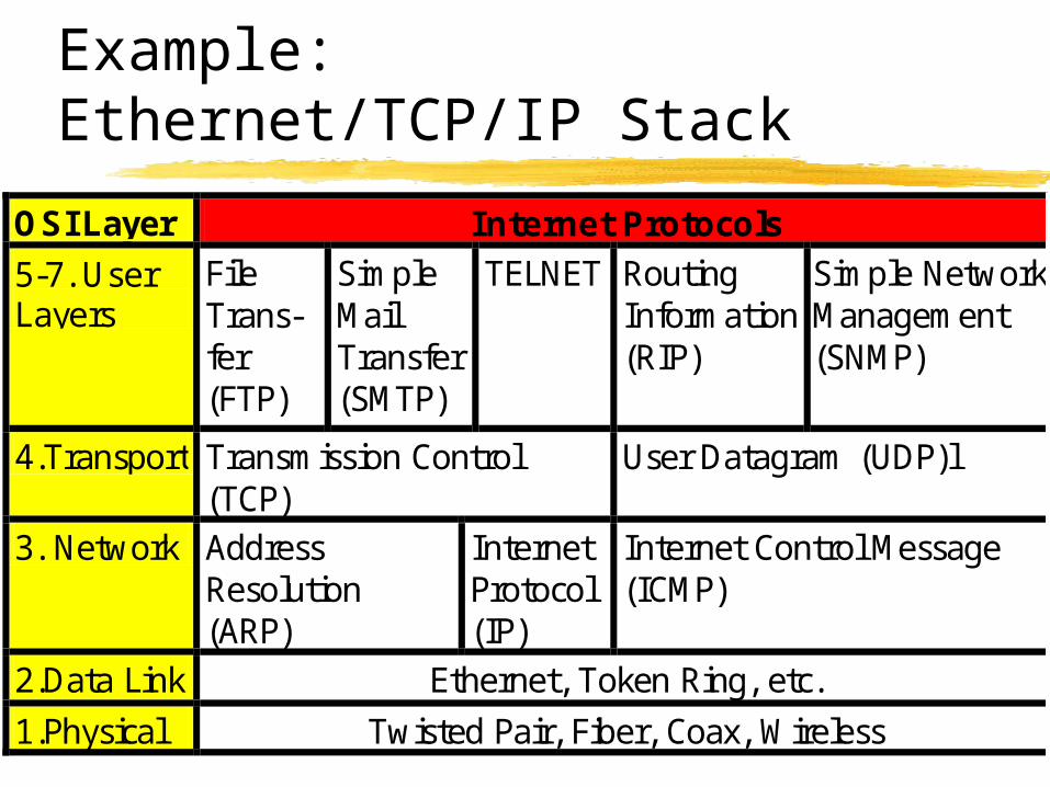
Example: Ethernet/TCP/IP Stack
OSI Layer Internet Protocols 5-7. User Layers
File Trans-fer (FTP)
Simple Mail Transfer (SMTP)
TELNET Routing Information (RIP)
Simple Network Management (SNMP)
4.Transport Transmission Control (TCP)
User Datagram (UDP)l
3. Network Address Resolution (ARP)
Internet Protocol (IP)
Internet Control Message (ICMP)
2.Data Link Ethernet, Token Ring, etc.
1.Physical Twisted Pair, Fiber, Coax, Wireless
Backbone Protocols

Out to the WAN “cloud”
Station
Router/Gateway
Firewall
WAN
CSU/DSU
LAN Backbone

CSU/DSU:Digital Service Unit/Channel Service Unit

CSU/DSU Wide area access
The Channel Service Unit terminates the external line at the customer's premises. It also provides diagnostics and allows for remote testing.
The Digital Service Unit does the actual transmission and receiving of the signal and provides buffering and flow control. The DSU and CSU are often in the same unit.

Dual Ring Topologies(FDDI & SONET)

Dual Ring Operation

Rerouted Ring

FDDIFiber Distributed Data Interface
Common Backbone Technology Two Fiber CablesDual Ring Configuration4500 byte frame limit100 MbpsPriority AccessMultiple Frame Transmission200 km (single mode fiber)

SONETSynchronous Optical NETwork
Backbone technology used by phone company.
Layer “1” Externally synchronized
810 byte frameDual ring topologyTime division multiplexing
Multiple simultaneous data streams

SONET CIRCUITS
Service Speed (Mbps) VT-1.5 1.7OC-1 STS-1 51.84OC-3 STS-3 155.52 (3 STS-1s)OC-12 STS-12 622.08 (4 STS-3)OC-48 STS-48 2488.32 (16 STS-3)OC-192 STS-192 9953.28 (64 STS-3)OC-768 STS-768 39813.12 (256 STS-3)
OC (Optical Carrier) refers to the optical signal, and STS (Synchronous Transport Signal) refers to the electrical signal

ATMAsynchronous Transfer mode
53 byte cell 5 byte header / 48 bytes of data
Single path for all packets in a message Dedicated circuit
Quality of Service Priorities

Typical SONET and ATM use as backbone technologies


32
1
3
12
Inter-networking