camill trueeb, carmelo sferrazza and raffaello d’andrea
TRANSCRIPT
Towards vision-based robotic skins:a data-driven, multi-camera tactile sensor
Camill Trueeb, Carmelo Sferrazza and Raffaello D’Andrea1
c©2020 IEEE. Personal use of this material is permitted. Permission from IEEE must be obtained for all other uses, in any current or future media,including reprinting/republishing this material for advertising or promotional purposes, creating new collective works, for resale or redistribution to serversor lists, or reuse of any copyrighted component of this work in other works.DOI: 10.1109/RoboSoft48309.2020.9116060
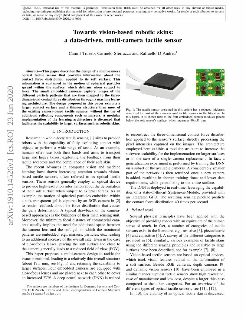
Abstract— This paper describes the design of a multi-cameraoptical tactile sensor that provides information about thecontact force distribution applied to its soft surface. Thisinformation is contained in the motion of spherical particlesspread within the surface, which deforms when subject toforce. The small embedded cameras capture images of thedifferent particle patterns that are then mapped to the three-dimensional contact force distribution through a machine learn-ing architecture. The design proposed in this paper exhibits alarger contact surface and a thinner structure than most ofthe existing camera-based tactile sensors, without the use ofadditional reflecting components such as mirrors. A modularimplementation of the learning architecture is discussed thatfacilitates the scalability to larger surfaces such as robotic skins.
I. INTRODUCTION
Research in whole-body tactile sensing [1] aims to providerobots with the capability of fully exploiting contact withobjects to perform a wide range of tasks. As an example,humans often use both their hands and arms to transportlarge and heavy boxes, exploiting the feedback from theirtactile receptors and the compliance of their soft skin.
The recent advances in computer vision and machinelearning have drawn increasing attention towards vision-based tactile sensors, often referred to as optical tactilesensors. These sensors generally employ an optical deviceto provide high-resolution information about the deformationof their soft surface when subject to external forces. As anexample, the motion of spherical particles embedded withina soft, transparent gel is captured by an RGB camera in [2]to render feedback about the force distribution that causesthe gel’s deformation. A typical drawback of the camera-based approaches is the bulkiness of their main sensing unit.Moreover, the minimum focal distance of commercial cam-eras usually implies the need for additional space betweenthe camera lens and the soft gel, in which the monitoredpatterns are embedded, e.g., markers, particles, etc., leadingto an additional increase of the overall size. Even in the caseof close-focus lenses, placing the soft surface too close tothe camera generally leads to a reduced field of view (FOV).
This paper proposes a multi-camera design to tackle theissues mentioned, leading to a relatively thin overall structure(about 17.5 mm, see Fig. 1) and retaining the scalability tolarger surfaces. Four embedded cameras are equipped withclose-focus lenses and are placed next to each other to coveran increased FOV. A deep neural network (DNN) is trained
1The authors are members of the Institute for Dynamic Systems and Con-trol, ETH Zurich, Switzerland. Email correspondence to Carmelo [email protected]
Fig. 1: The tactile sensor presented in this article has a reduced thicknesscompared to most of the camera-based tactile sensors in the literature. Inthis figure, it is shown next to the four embedded camera modules placedbelow the soft sensor’s surface, which measures 49×51 mm.
to reconstruct the three-dimensional contact force distribu-tion applied to the sensor’s surface, directly processing thepixel intensities captured on the images. The architectureemployed here exhibits a modular structure to increase thesoftware scalability for the implementation on larger surfacesor in the case of a single camera replacement. In fact, ageneralization experiment is performed by training the DNNon a subset of the available cameras. A considerably smallerpart of the network is then retrained once a new camerais added, resulting in shorter training times and lower datarequirements, while generalizing to the entire surface.
The DNN is deployed in real-time, leveraging the capabil-ities of a state-of-the-art System-on-Module, provided withan integrated GPU. The resulting sensing pipeline predictsthe contact force distribution 40 times per second.
A. Related work
Several physical principles have been applied with theobjective of providing robots with an equivalent of the humansense of touch. In fact, a number of categories of tactilesensors exist in the literature, e.g., resistive [3], piezoelectric[4] and capacitive [5]. A survey of the different categories isprovided in [6]. Similarly, various examples of tactile skinsusing the different sensing principles and scalable to largesurfaces have been described, see for example [7], [8].
Vision-based tactile sensors are based on optical devices,which track visual features related to the deformation ofa soft surface. Beside RGB cameras, depth cameras [9]and dynamic vision sensors [10] have been employed in asimilar manner. Optical tactile sensors show high resolution,ease of manufacture and low cost, despite a larger thicknesscompared to the other categories. For an overview of thedifferent types of optical tactile sensors, see [11], [12].
In [13], the viability of an optical tactile skin is discussed.
arX
iv:1
910.
1452
6v3
[cs
.RO
] 2
3 Ju
n 20
20

The availability of inexpensive and low power GPUs isindicated as a possible solution to enable the real-timeprocessing of a large number of tactile images. Two cameraswere mounted on each finger of a soft robotic gripper in [14]to classify the shape and size of an object. The classificationis performed by means of a DNN that takes as input theconcatenation of the two images. A finger-shaped gripper ispresented in [15]. Tactile imprints are redirected via a mirrortowards a camera to increase the sensor compactness. Twocameras are used in [16] to reconstruct the 3D displacementof inner markers in a soft tactile muscularis.
In order to overcome the complexity of interpreting thetactile information, several learning-based approaches havebeen applied to measure various tactile quantities. The loca-tion and depth of an indentation are reconstructed in [17] ona sensor based on an array of light emitters and receivers.In [18] a deep learning architecture estimates the total forceand torque applied to a tactile sensor, which uses photometricstereo and markers painted on its surface. In [19], a neuralnetwork reconstructs the contact force distribution appliedto the soft surface of a vision-based sensor. Ground truthlabels are provided via the use of simulations based onthe finite element method (FEM). In order to share theknowledge acquired from data across different sensors, atransfer learning approach is proposed in [20].
The approach presented here is based on four camerasplaced at a short distance from the observed surface, whichhas a random spread of spherical particles embedded. Thechoice of the components and the data-driven approach makeit possible to obtain a thin structure without the use ofadditional reflecting components, hence simplifying manu-facture. The network architecture employed is tailored tothe use of multiple cameras, introducing modularity featuresand facilitating the scalability of the approach. The resultingpipeline reconstructs with high accuracy the contact forcedistribution applied by a sample indenter to the soft surfaceof the sensor, including the regions where the indentation isnot fully covered by the FOV of a single camera.
B. Outline
The sensing principle and the hardware used for theexperiments are described in Section II. A dimensioninganalysis then discusses the possibility of further reducing thethickness of the sensor. The data collection and the learningarchitecture are detailed in Section III. The results and amodularity evaluation are presented in Section IV. Remarksin Section V conclude the paper.
II. SENSOR DESIGN
A four-camera design is first introduced in this section.Compared to previous work it shows a thinner sensor witha larger sensing surface. The outlook for a further reductionof the thickness of the design is discussed in the second partof the section.
Flat Ribbon Connectors
(a) bottom view
Cameras
(b) top view
Fig. 2: The sensor’s base structure accommodates four Raspberry Pi v2camera interface boards with flat ribbon cable connectors (a) and thecameras mounted on top (b).
A. Hardware
The optical tactile sensor is based on the tracking ofunicolored particles (polyethylene microspheres with a di-ameter of 150 to 180µm) randomly spread within a soft,transparent silicone gel. The motion of the particles iscaptured by four rectangularly arranged cameras (RaspberryPi Camera Module v2), see Fig. 2. These cameras capture40 frames per second at a resolution of 320×240 pixels. Theframes are eventually cropped and downsampled to 128×128pixels. In order to reduce the thickness of the sensor, thedefault Raspberry Pi camera lenses are replaced by fisheyelenses originally mounted on Sincerefirst SF-C7251OV-H133cameras. The lenses are mounted onto the camera framesover distance rings, whose thickness is designed to obtainthe desired focus. Finally, an LED board is placed over thecamera array to provide uniform brightness.
Similarly to [2], three different silicone layers are cast ontothe camera array, as shown in Fig. 3. From the bottom, thefirst layer is relatively stiff and adds the distance betweenthe camera and the particles, which is necessary to improvethe focus. This layer also provides additional protection forthe hardware and ensures light diffusion. The second layer isthe softest and contains the particles tracked by the cameras.Finally, the third layer (stiffer than the second) is cast witha black color and protects the sensor from external lightsources and material damage. The same materials, mixingratios and curing protocol as in [19] were used, for aresulting sensing surface of 49×51 mm. Each embedded
Fig. 3: The cameras and an LED board are fixed to a base structure. Threesilicone layers are directly poured onto the LED board and the cameralenses: A stiff transparent layer, the particle layer and a black protectionlayer.
camera is controlled by a separate, relatively inexpensivesingle-board computer (Raspberry Pi 3 model B+). Theseboards communicate with a System-on-Module (NVIDIA
Jetson Nano Developer Kit), which is equipped with a 64-bit quad-core Arm Cortex-A57 CPU alongside a MaxwellGPU with 128 CUDA cores. The communication is handledby a Gigabit Ethernet switch (ANDDEAR QZ001), whichenables the Jetson Nano to receive the four image streams.The Jetson Nano provides a clock source to the RaspberryPi boards, which are synchronized through the NetworkingTime Protocol (NTP), to ensure contemporaneous imagestreams. Note that the Raspberry Pi boards and the Ethernetswitch may be replaced by compact, commercially availablemulti-camera adapter boards for the Jetson Nano. However,drivers for these adapter boards are still under developmentor not easily accessible because of the relatively recentrelease of the Jetson Nano. This aspect has not been furtherinvestigated for the purpose of this work.
B. Dimensioning analysis
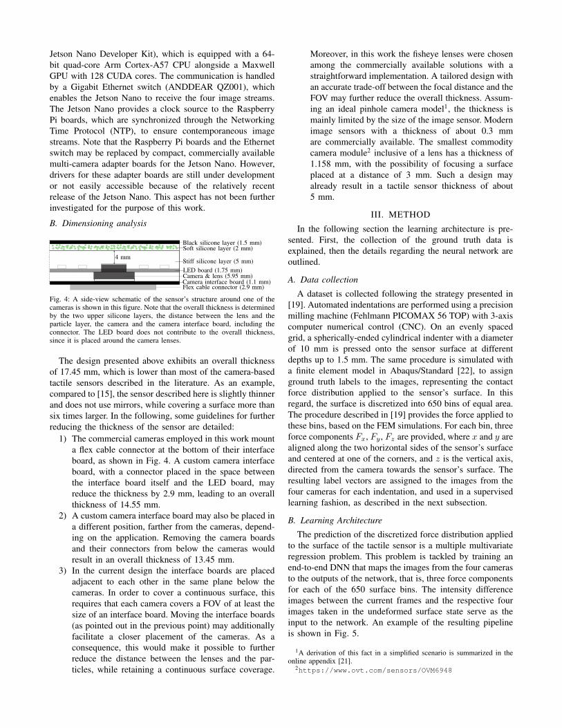
Black silicone layer (1.5 mm)Soft silicone layer (2 mm)
Stiff silicone layer (5 mm)
Camera & lens (5.95 mm)
Flex cable connector (2.9 mm)
LED board (1.75 mm)
4 mm
Camera interface board (1.1 mm)
Fig. 4: A side-view schematic of the sensor’s structure around one of thecameras is shown in this figure. Note that the overall thickness is determinedby the two upper silicone layers, the distance between the lens and theparticle layer, the camera and the camera interface board, including theconnector. The LED board does not contribute to the overall thickness,since it is placed around the camera lenses.
The design presented above exhibits an overall thicknessof 17.45 mm, which is lower than most of the camera-basedtactile sensors described in the literature. As an example,compared to [15], the sensor described here is slightly thinnerand does not use mirrors, while covering a surface more thansix times larger. In the following, some guidelines for furtherreducing the thickness of the sensor are detailed:
1) The commercial cameras employed in this work mounta flex cable connector at the bottom of their interfaceboard, as shown in Fig. 4. A custom camera interfaceboard, with a connector placed in the space betweenthe interface board itself and the LED board, mayreduce the thickness by 2.9 mm, leading to an overallthickness of 14.55 mm.
2) A custom camera interface board may also be placed ina different position, farther from the cameras, depend-ing on the application. Removing the camera boardsand their connectors from below the cameras wouldresult in an overall thickness of 13.45 mm.
3) In the current design the interface boards are placedadjacent to each other in the same plane below thecameras. In order to cover a continuous surface, thisrequires that each camera covers a FOV of at least thesize of an interface board. Moving the interface boards(as pointed out in the previous point) may additionallyfacilitate a closer placement of the cameras. As aconsequence, this would make it possible to furtherreduce the distance between the lenses and the par-ticles, while retaining a continuous surface coverage.
Moreover, in this work the fisheye lenses were chosenamong the commercially available solutions with astraightforward implementation. A tailored design withan accurate trade-off between the focal distance and theFOV may further reduce the overall thickness. Assum-ing an ideal pinhole camera model1, the thickness ismainly limited by the size of the image sensor. Modernimage sensors with a thickness of about 0.3 mmare commercially available. The smallest commoditycamera module2 inclusive of a lens has a thickness of1.158 mm, with the possibility of focusing a surfaceplaced at a distance of 3 mm. Such a design mayalready result in a tactile sensor thickness of about5 mm.
III. METHOD
In the following section the learning architecture is pre-sented. First, the collection of the ground truth data isexplained, then the details regarding the neural network areoutlined.
A. Data collection
A dataset is collected following the strategy presented in[19]. Automated indentations are performed using a precisionmilling machine (Fehlmann PICOMAX 56 TOP) with 3-axiscomputer numerical control (CNC). On an evenly spacedgrid, a spherically-ended cylindrical indenter with a diameterof 10 mm is pressed onto the sensor surface at differentdepths up to 1.5 mm. The same procedure is simulated witha finite element model in Abaqus/Standard [22], to assignground truth labels to the images, representing the contactforce distribution applied to the sensor’s surface. In thisregard, the surface is discretized into 650 bins of equal area.The procedure described in [19] provides the force applied tothese bins, based on the FEM simulations. For each bin, threeforce components Fx, Fy , Fz are provided, where x and y arealigned along the two horizontal sides of the sensor’s surfaceand centered at one of the corners, and z is the vertical axis,directed from the camera towards the sensor’s surface. Theresulting label vectors are assigned to the images from thefour cameras for each indentation, and used in a supervisedlearning fashion, as described in the next subsection.
B. Learning Architecture
The prediction of the discretized force distribution appliedto the surface of the tactile sensor is a multiple multivariateregression problem. This problem is tackled by training anend-to-end DNN that maps the images from the four camerasto the outputs of the network, that is, three force componentsfor each of the 650 surface bins. The intensity differenceimages between the current frames and the respective fourimages taken in the undeformed surface state serve as theinput to the network. An example of the resulting pipelineis shown in Fig. 5.
1A derivation of this fact in a simplified scenario is summarized in theonline appendix [21].
2https://www.ovt.com/sensors/OVM6948

Fig. 5: The sensing pipeline is shown in this figure. An indentation produces a change in the particle pattern that is visible in the difference of the pixelintensities (central image) between the current frame and a frame taken at rest. The DNN predicts the three-dimensional contact force distribution appliedduring the indentation. The last figure on the right shows a color visualization of the resulting Fz for each of the surface bins.
4×4
conv
,4
3×3
conv
,2
3×3
conv
,6
3×3
conv
,8
1/2
pool
ing
1/2
pool
ing
900
FC
600
FC
300
FC
FUSI
ON
1
2
4
3
Fx
Fy
Fz
CNN
Fig. 6: This figure shows the architecture of the network. Each differenceimage is separately fed through the same CNN, and the outputs are thencombined via a fusion layer. For ease of visualization, some abbreviationshave been introduced in the block diagram above. In this regard, the label“3×3 conv, 2” refers to a two-channel convolutional layer with a 3×3kernel, while “1/2 pooling” indicates a max pooling layer, which subsamplesthe input to half of its original size. “900 FC” refers to a fully connectedlayer with 900 units.
To decouple the detection of features that are independentof the cameras’ placement, the difference images from thefour cameras are fed independently through a convolutionalneural network (CNN). Only after this intermediate network,a fusion layer with a linear activation function combinesthe four different output tensors and predicts the three-dimensional discretized force distribution. Both the overallnetwork layout and the dimensions of the different layers areshown in Fig. 6.
The CNN takes a difference image of size 128×128 asan input. Batch normalization showed a large decrease inthe network training times and is used for all convolutionallayers, together with rectified linear unit activation functions.A dropout rate of 0.1 is used on the fully connected (FC)layers to prevent overfitting to the training data, together withsigmoid activation functions. The root mean squared error(RMSE) is used as a loss function for the Adam optimizer[23] to train the model. 30% of the dataset was put aside forevaluation purposes.
The fact that the CNN is shared between the four cameras
leads to a considerable reduction in the memory consump-tion, especially in view of the possible extension to largersurfaces with a higher number of cameras. Moreover, thisgenerally leads to a smaller network size, in contrast tofeeding the concatenation of the four images through alarger architecture. Smaller architectures tend to require lesstraining data and exhibit shorter training times. Finally, thearchitecture presented here shows modularity features. Theseare discussed in Section IV.
IV. RESULTS
In this section, the performance of the multi-camera tactilesensor is evaluated. In the first part of the section, theevaluation of the learning architecture is presented. In thesecond part, an experiment is performed by modifying theneural network and the training procedure in order to testthe modularity of the approach.
A. Sensor Performance
The DNN presented in Section III-B is trained on 70% ofthe full dataset. 10% of the samples are used as a validationset to apply early stopping during training. The remaining20% is left aside for evaluation. The resulting RMSE onthe force distribution is 0.00060 N, 0.00059 N, 0.0019 Nfor Fx, Fy , Fz , respectively, while the resulting RMSE onthe total applied force (sum of the forces of all surfacebins) is 0.0019 N, 0.0016 N, 0.0571 N for Fx, Fy , Fz ,respectively. Note that the dataset is generated from verticalindentations, with the resulting total forces in z-direction upto 3 N, and considerably smaller total forces in the horizontaldirection on most of the sensor surface. Fig. 7 shows anexample prediction of the contact force distribution in z-direction and the corresponding ground truth. The modelinference runs on the Jetson Nano at 86 Hz, which makes theframe capturing (40 frames per second) on the Raspberry Piboards the bottleneck of the sensing speed. As a result, thesensing pipeline runs at a maximal prediction speed of 40Hz. Furthermore, the fact that the four simultaneous imagesare fed independently through the CNN enables the detectionof multiple contact points, when each camera fully capturesup to one of the distinct contact patches, even if the modelhas only been trained with single indentations. This makesit possible to detect up to four distinct contact patches, as

shown in the video attached to this submission.
0 25 49x [mm]
51
25
0
y[m
m]
Reference Force
0 25 49x [mm]
Predicted Force
-0.40
-0.32
-0.24
-0.16
-0.08
0.00
Fz
[N]
Fig. 7: The figure shows the component Fz of each surface bin for anexample indentation in the test set. On the left, the ground truth forcedistribution is shown, and on the right, the distribution predicted by theneural network.
B. Sensor Modularity
To evaluate the modularity of the approach, a first model istrained using only images and labels from three cameras. Ina second step, the sensor is recalibrated with the training datafrom all four cameras. The procedure is schematically shownin Fig. 8. For the calibration step, the majority of the DNNparameters are frozen, and only the last fully connected layerand the fusion layer are retrained. This serves the purposeof reducing the training times and the data requirements.
CNN
FUSI
ON
1
2
3
Fx
Fy
Fz
FUSI
ON
1
2
4
3CNN∗
FC30
0 Fx
Fy
Fz
1) Training with data from 3 cameras:
2) Recalibration with data from 4th camera:
Fig. 8: The model is first trained with the data from three cameras, and thenextended to four cameras and recalibrated with the full dataset. In the firstplot the fusion layer contains 900 units, mapping the outputs correspondingto the surface covering only three cameras. In the second plot, the size ofthe fusion layer is increased to 1200 units, to cover the entire surface.
As shown in Fig. 9, the recalibrated network showscomparable performance to the model trained on thewhole data in Section IV-A. Moreover, the performanceis retained using an even smaller portion of training data.The plots show the different error metrics as a functionof the percentage of data used for training. Retraining
the last two layers takes approximately 1.5 hours on theemployed GPU (Nvidia TITAN X Pascal), as opposed toover 10 hours training for the whole model on the fulldataset. This experiment shows promising results towardsthe possibility of training the most resource (both timeand data) consuming part of the network on a subset ofthe surface, therefore reducing the data collection and thetraining times on the rest of the surface. This also opens theopportunity of replacing a defective camera (although notcurrently possible in the experimental prototype presented)on a large-scale skin, without the need to retrain the entirenetwork.
V. CONCLUSION
In this paper, a multi-camera tactile sensing approachhas been presented, making use of an end-to-end DNN topredict the force distribution on the sensor surface. Thesensor thickness has been reduced, while at the same timethe sensing surface has been extended using multiple camerasarranged in an array. A relatively inexpensive sensor designhas been suggested, using Raspberry Pi cameras to capturesynchronized images and a Jetson Nano Developer Kit forthe model inference.
A neural network has been presented to reconstruct thecontact force distribution. The modular architecture proposedhere is applicable to optical tactile sensors with a larger num-bers of cameras, such as vision-based robotic skins. It hasbeen shown how the network can be efficiently recalibratedwhen the number of cameras is increased, without retrainingany of the convolutional layers. The sensing pipeline pre-sented here runs on an embedded computer provided with aGPU at 40 Hz. On the test dataset employed, the architecturehas shown an RMSE of 0.0571 N on the total forces in thevertical direction that were collected up to 3 N.
The procedure proposed here to attach the lenses to thecamera frames does not yield a very accurate focus of theimages (see Fig. 5) and needs further investigation. Futurework will also include the extension of this approach tovarious directions and shapes of the indentations, as well asa quantitative scalability analysis in the case of an increasingnumber of cameras.
ACKNOWLEDGMENT
The authors would like to thank Michael Egli and MatthiasMuller for their support in the sensor manufacture.
REFERENCES
[1] V. J. Lumelsky, Sensing, Intelligence, Motion: How Robots andHumans Move in an Unstructured World. John Wiley & Sons, 2005.
[2] C. Sferrazza and R. D’Andrea, “Design, Motivation and Evaluationof a Full-Resolution Optical Tactile Sensor,” Sensors, vol. 19, no. 4:928, 2019.
[3] K. Weiß and H. Worn, “The Working Principle of Resistive TactileSensor Cells,” in IEEE International Conference Mechatronics andAutomation, 2005, vol. 1, pp. 471–476.
[4] C. Li, P.-M. Wu, S. Lee, A. Gorton, M. J. Schulz, and C. H. Ahn,“Flexible Dome and Bump Shape Piezoelectric Tactile Sensors UsingPVDF-TrFE Copolymer,” Journal of Microelectromechanical Systems,vol. 17, no. 2, pp. 334–341, 2008.

0 25 50 75 100Training Data [%]
0.0000
0.0002
0.0004
0.0006
0.0008
0.0010
RM
SE
[N]
x
y
(a) RMSE on the force distribution (x and y axes)
0 25 50 75 100Training Data [%]
0.000
0.001
0.002
0.003
0.004
0.005
Tota
lFor
ceR
MS
E[N
]
x
y
(b) RMSE on the total force (x and y axes)
0 25 50 75 100Training Data [%]
0.000
0.001
0.002
0.003
0.004
RM
SE
[N]
(c) RMSE on the force distribution (z axis)
0 25 50 75 100Training Data [%]
0.00
0.02
0.04
0.06
0.08
Tota
lFor
ceR
MS
E[N
](d) RMSE on the total force (z axis)
Fig. 9: After the neural network is trained on the data from three cameras, it is recalibrated for the fourth camera with a portion of the training datafrom all the cameras. The resulting errors are shown above, as a function of the varying percentage of the full dataset used for training, together with aleast-squares trend line.
[5] J. M. Romano, K. Hsiao, G. Niemeyer, S. Chitta, and K. J. Kuchen-becker, “Human-inspired Robotic Grasp Control with Tactile Sensing,”IEEE Transactions on Robotics, vol. 27, no. 6, pp. 1067–1079, 2011.
[6] R. S. Dahiya, G. Metta, M. Valle, and G. Sandini, “Tactile Sensing–From Humans to Humanoids,” IEEE Transactions on Robotics, vol. 26,no. 1, pp. 1–20, 2009.
[7] H. Lee, K. Park, J. Kim, and K. J. Kuchenbecker, “A Large-ScaleFabric-Based Tactile Sensor Using Electrical Resistance Tomography,”in Haptic Interaction, H. Kajimoto, D. Lee, S.-Y. Kim, M. Konyo, andK.-U. Kyung, Eds. Springer Singapore, 2019, pp. 107–109.
[8] G. Cannata, M. Maggiali, G. Metta, and G. Sandini, “An embeddedartificial skin for humanoid robots,” in 2008 IEEE InternationalConference on Multisensor Fusion and Integration for IntelligentSystems, pp. 434–438.
[9] A. Alspach, K. Hashimoto, N. Kuppuswarny, and R. Tedrake, “Soft-bubble: A highly compliant dense geometry tactile sensor for robotmanipulation,” in 2019 2nd IEEE International Conference on SoftRobotics (RoboSoft), pp. 597–604.
[10] F. B. Naeini, A. Alali, R. Al-Husari, A. Rigi, M. K. AlSharman,D. Makris, and Y. Zweiri, “A Novel Dynamic-Vision-Based Approachfor Tactile Sensing Applications,” IEEE Transactions on Instrumenta-tion and Measurement, 2019.
[11] K. Shimonomura, “Tactile Image Sensors Employing Camera: AReview,” Sensors, vol. 19, no. 18, p. 3933, 2019.
[12] A. Yamaguchi and C. G. Atkeson, “Recent progress in tactile sensingand sensors for robotic manipulation: can we turn tactile sensing intovision?” Advanced Robotics, vol. 33, no. 14, pp. 661–673, 2019.
[13] ——, “Optical Skin For Robots: Tactile Sensing And Whole-BodyVision,” in Workshop on Tactile Sensing for Manipulation, Robotics:Science and Systems (RSS), vol. 25, 2017, pp. 133–134.
[14] Y. She, S. Q. Liu, P. Yu, and E. Adelson, “Exoskeleton-covered softfinger with vision-based proprioception and exteroception,” 2019.
[15] E. Donlon, S. Dong, M. Liu, J. Li, E. Adelson, and A. Rodriguez,“GelSlim: A High-Resolution, Compact, Robust, and Calibrated
Tactile-sensing Finger,” in 2018 IEEE/RSJ International Conferenceon Intelligent Robots and Systems (IROS), pp. 1927–1934.
[16] L. Van Duong, R. Asahina, J. Wang et al., “Development of aVision-Based Soft Tactile Muscularis,” in 2019 2nd IEEE InternationalConference on Soft Robotics (RoboSoft), pp. 343–348.
[17] P. Piacenza, E. Hannigan, C. Baumgart, Y. Xiao, S. Park,K. Behrman, W. Dang, J. Espinal, I. Hussain, I. Kymissis,and M. Ciocarlie, “Touch Sensors with Overlapping Signals:Concept Investigation on Planar Sensors with Resistive or OpticalTransduction,” CoRR, vol. abs/1802.08209, 2019. [Online]. Available:http://arxiv.org/abs/1802.08209
[18] W. Yuan, S. Dong, and E. Adelson, “Gelsight: High-Resolution RobotTactile Sensors for Estimating Geometry and Force,” Sensors, vol. 17,no. 12, p. 2762, 2017.
[19] C. Sferrazza, A. Wahlsten, C. Trueeb, and R. DAndrea, “GroundTruth Force Distribution for Learning-Based Tactile Sensing: A FiniteElement Approach,” IEEE Access, vol. 7, pp. 173 438–173 449, 2019.
[20] C. Sferrazza and R. D’Andrea, “Transfer learning for vision-basedtactile sensing,” in 2019 IEEE/RSJ International Conference on Intel-ligent Robots and Systems (IROS), pp. 7961–7967.
[21] C. Trueeb, C. Sferrazza, and R. D’Andrea, “Online appendix - On thethickness of vision-based tactile sensors,” 2019. [Online]. Available:https://arxiv.org/src/1910.14526/anc/OnlineAppendix.pdf
[22] Dassault Systemes, Abaqus/Standard User’s Manual, v. 6.14, 2014.[23] D. P. Kingma and J. L. Ba, “Adam: A Method for Stochastic
Optimization,” in Proceedings of the International Conference onLearning Representations (ICLR), 2015.