camera debrief christopher stubbs dm all-hands meeting 12 february 2015 1
TRANSCRIPT

1
Camera debrief
Christopher StubbsDM All-Hands meeting
12 February 2015

2
1/3 RTM test
O’Connor, Kuczewski, Juramy, Haupt2/6/2015

3
Setup• 3 CCD250 prototype sensors on
CeSiC raft baseplate• One REB2 + DREB1 in vertical slice
(TS7) cryostat– 6X ASPIC3– 6X CABAC0
• REC mockup• read_ccd_480kHz.ssf sequencer
file: – 480kpix/s, no serials during
exposure, fast clear once on startup• Clock and bias settings:
– OD/RD/GD 28/18/28– Clocks +10/0, RG
• Setpoints:– RSA -100C– coldplate -10C

4
Flatfields ~170kADU

5
Image

6
PTC with polyfit(2)
mean of sum image ADU
Var
of
diff
imag
e A
DU
2
Note: ½ of channels have different gain setting resistors populated on REB

7
Gains
0.0 0.5 1.0 1.5 2.0
0.5
00
.55
0.6
00
.65
0.7
00
.75
0.8
0
chip
ga
in, e
-/A
DU
5 10 15
0.5
00
.55
0.6
00
.65
0.7
00
.75
0.8
0
chang
ain
, e-/
AD
U
Black – chipARed – chipBGreen - chipC
Black – topRed – bot
A B C
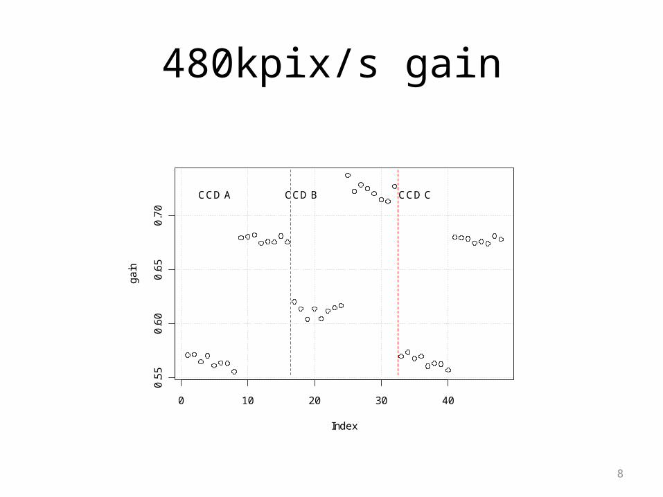
Note: CCD B has lower sensitivity than A or C due to AR coating difference (see slide 8)Note: ½ of channels have different gain setting resistors populated on REB
8
480kpix/s gain
0 10 20 30 40
0.5
50
.60
0.6
50
.70
Index
ga
in
CCD A CCD B CCD C

9
CCD C
CCD B
CCD A

10
480kpix/s noise
0 5 10 15
56
78
9
segment
no
ise
, e-
Black – chipARed – chipBGreen - chipC
channel

11
Mean vs. exptime
Linearity
Note: ½ of channels have different gain setting resistors populated on REBCCD A one ASPIC gain setting is 2X

12
“Sampling scope” diagnostic mode• Using normal video channel
ADCs, can measure repetitive waveforms by delaying the timing of the convert pulse on successive pixel cycles.
• LPNHE-provided firmware performs this automatically
• Can set ASPIC into “transparent “ mode to visualize CCD OS waveform
• Equivalent to an 18-bit, 100MHz sampling oscilloscope
vo
ltag
e
reset feedthru
reset level
video level
ramp down
ramp up
ASPIC reset
13
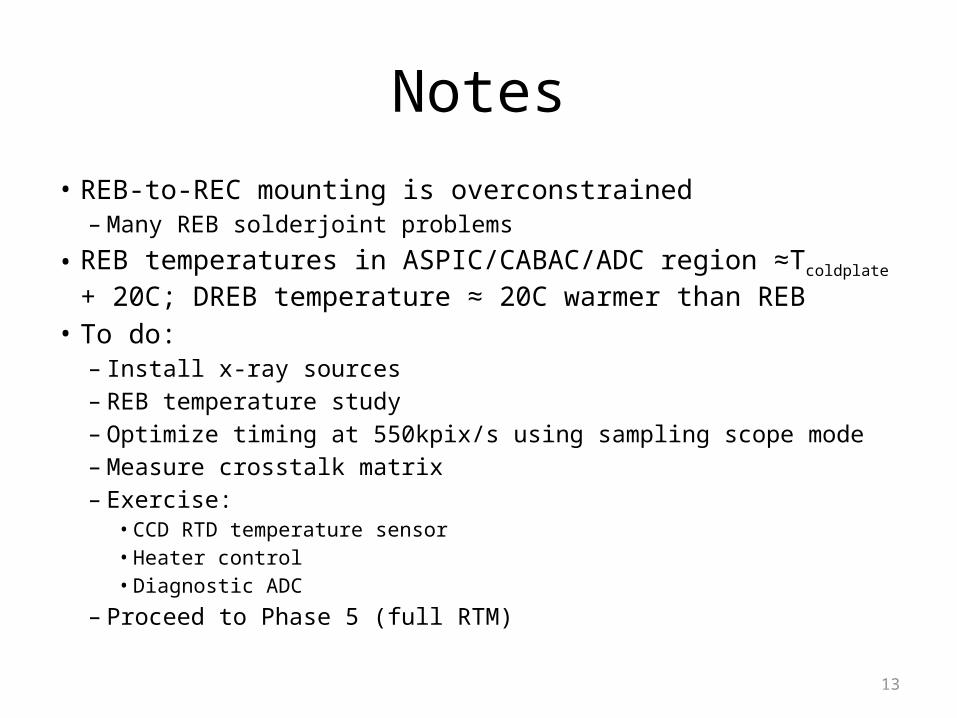
Notes• REB-to-REC mounting is overconstrained
– Many REB solderjoint problems
• REB temperatures in ASPIC/CABAC/ADC region ≈Tcoldplate + 20C; DREB temperature ≈ 20C warmer than REB
• To do:– Install x-ray sources – REB temperature study– Optimize timing at 550kpix/s using sampling scope mode– Measure crosstalk matrix– Exercise:
• CCD RTD temperature sensor• Heater control• Diagnostic ADC
– Proceed to Phase 5 (full RTM)
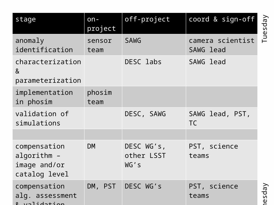
stage on-project off-project coord & sign-off
anomaly identification sensor team
SAWG camera scientistSAWG lead
characterization & parameterization
DESC labs SAWG lead
implementation in phosim
phosim team
validation of simulations
DESC, SAWG SAWG lead, PST, TC
compensation algorithm – image and/or catalog level
DM DESC WG’s, other LSST WG’s
PST, science teams
compensation alg. assessment & validation
DM, PST DESC WG’s PST, science teams
quantify residuals and systematic error
DM, PST DESC WG’s PST, science teams
Wed
nesd
ay
Tue
sday

15
BACKUP
16
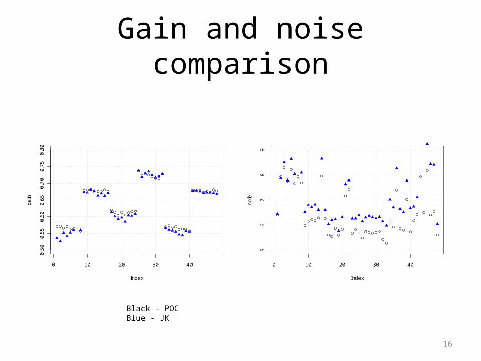
Gain and noise comparison
0 10 20 30 40
0.5
00
.55
0.6
00
.65
0.7
00
.75
0.8
0
Index
ga
in
0 10 20 30 405
67
89
Index
no
ie
Black – POCBlue - JK

17
ratios
0 10 20 30 40
0.9
00
.95
1.0
01
.05
1.1
0
Index
jk[,
3]/g
ain
0 10 20 30 400
.00
.51
.01
.52
.0
Index
jk[,
4]/n
oie
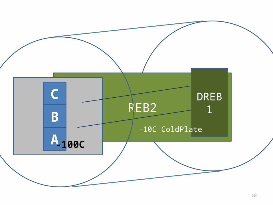
18
REB2
A
B
CDREB1
-100C
-10C ColdPlate