camera
TRANSCRIPT
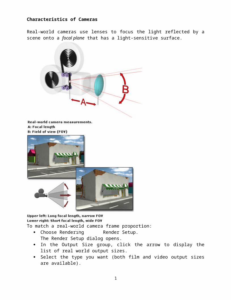
Characteristics of Cameras
Real-world cameras use lenses to focus the light reflected by a scene onto a focal plane that has a light-sensitive surface.
To match a real-world camera frame proportion: Choose Rendering Render Setup.
The Render Setup dialog opens. In the Output Size group, click the arrow to display the list of real world output sizes. Select the type you want (both film and video output sizes are available). Right-click the Camera viewport label, and turn on Show Safe Frame.
The Safe Frame proportions will match those of the selected output size.Exposure Control in Real-World Cameras
1
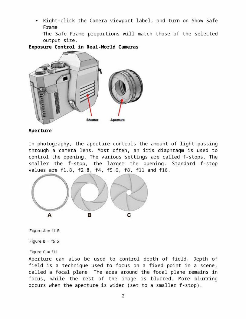
Aperture
In photography, the aperture controls the amount of light passing through a camera lens. Most often, an iris diaphragm is used to control the opening. The various settings are called f-stops. The smaller the f-stop, the larger the opening. Standard f-stop values are f1.8, f2.8, f4, f5.6, f8, f11 and f16.
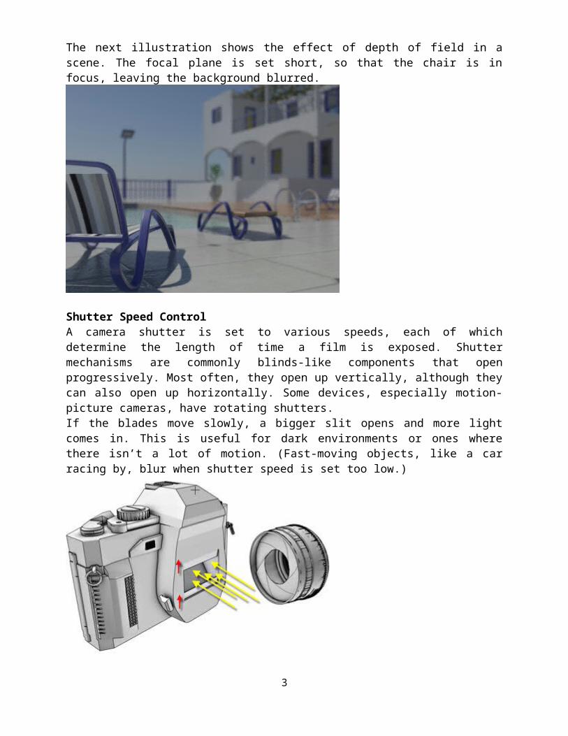
Aperture can also be used to control depth of field. Depth of field is a technique used to focus on a fixed point in a scene, called a focal plane. The area around the focal plane remains in focus, while the rest of the image is blurred. More blurring occurs when the aperture is wider (set to a smaller f-stop).The next illustration shows the effect of depth of field in a scene. The focal plane is set short, so that the chair is in focus, leaving the background blurred.
2
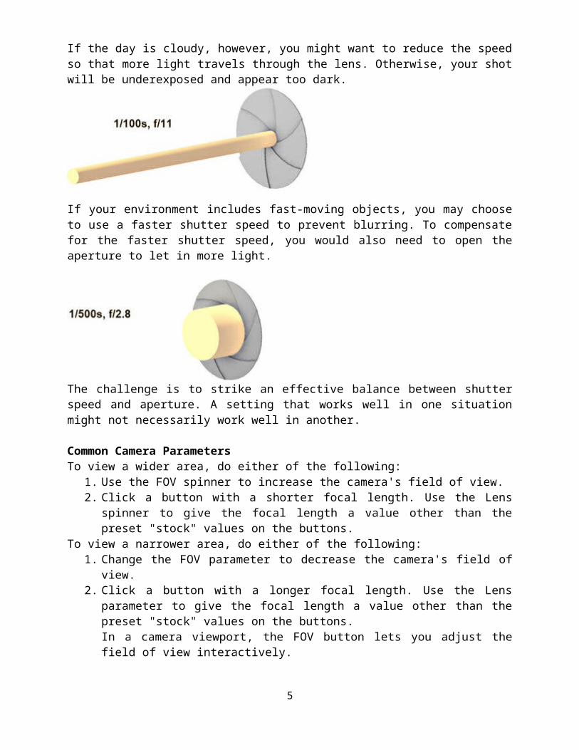
Shutter Speed ControlA camera shutter is set to various speeds, each of which determine the length of time a film is exposed. Shutter mechanisms are commonly blinds-like components that open progressively. Most often, they open up vertically, although they can also open up horizontally. Some devices, especially motion-picture cameras, have rotating shutters.If the blades move slowly, a bigger slit opens and more light comes in. This is useful for dark environments or ones where there isn’t a lot of motion. (Fast-moving objects, like a car racing by, blur when shutter speed is set too low.)
If the blades move fast, the slit is smaller and less light travels through the lens. This is useful for fast-moving action or bright environments with sun, snow, and sand.
3

Aperture and Shutter SpeedThe following graphic illustrates the amount of light going through a lens set to an aperture opening of f11. In Figure A, shutter speed is fast and only a small amount of light travels through. In Figure B, shutter speed is slow and more light travels through.
Usually, you need to adjust both the shutter speed and aperture value to ensure that an optimum amount of light enters the camera.In an exterior setting on a sunny day, for example, you would combine a faster shutter speed with a small aperture to compensate for the bright environment.
If the day is cloudy, however, you might want to reduce the speed so that more light travels through the lens. Otherwise, your shot will be underexposed and appear too dark.
4
If your environment includes fast-moving objects, you may choose to use a faster shutter speed to prevent blurring. To compensate for the faster shutter speed, you would also need to open the aperture to let in more light.
The challenge is to strike an effective balance between shutter speed and aperture. A setting that works well in one situation might not necessarily work well in another.
Common Camera ParametersTo view a wider area, do either of the following:
1. Use the FOV spinner to increase the camera's field of view. 2. Click a button with a shorter focal length. Use the Lens spinner to give the focal length a
value other than the preset "stock" values on the buttons.To view a narrower area, do either of the following:
1. Change the FOV parameter to decrease the camera's field of view. 2. Click a button with a longer focal length. Use the Lens parameter to give the focal length
a value other than the preset "stock" values on the buttons. In a camera viewport, the FOV button lets you adjust the field of view interactively.The camera viewport Perspective button also changes the FOV in conjunction with dollying the camera.
To set the camera lens size:1. In the Stock Lenses group, click a button to choose a stock focal length. 2. Set the Lens spinner to a custom focal length.
To match a camera to a film or video format:1. On the Render Setup dialog, in the Output Size group Output Size group, choose the type
of output you want. Use either of the following methods. o Choose a preset, such as HDTV (video), from the drop-down list. The Aperture
Width is locked to the preset's values.o Choose Custom, and then set the desired Aperture Width value. (You can adjust
the other output values at any later time. They have no affect on the camera lens settings, although they do affect the cropping of the scene.)
2. After setting Aperture Width, set the Lens value for the camera to the type of camera lens you want to emulate (for example, 50mm).
5

To maintain the same lens, avoid using the FOV or Perspective controls among the navigation icon buttons.
To find a lens's focal length: To find the focal length of a lens based on changes in aperture width, open the Render
Setup dialog, choose Custom from the Output Size drop-down list, and specify a value in the Aperture Width spinner. The new value of the camera's Lens parameter is based on the new Aperture Width value.
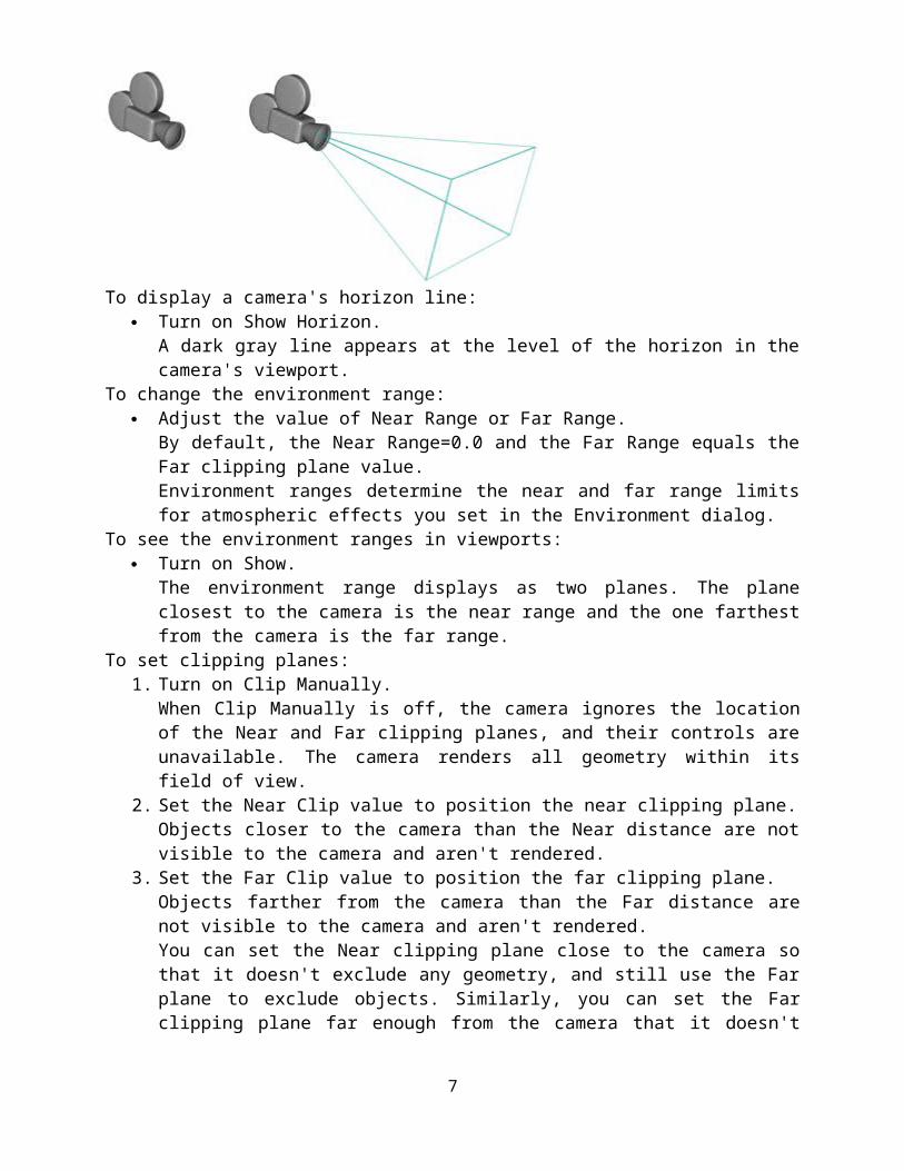
To display a camera's cone: Turn on Show Cone.
The camera's field-of-view cone appears outlined in light blue.
To display a camera's horizon line: Turn on Show Horizon.
A dark gray line appears at the level of the horizon in the camera's viewport.To change the environment range:
Adjust the value of Near Range or Far Range. By default, the Near Range=0.0 and the Far Range equals the Far clipping plane value.Environment ranges determine the near and far range limits for atmospheric effects you set in the Environment dialog.
To see the environment ranges in viewports: Turn on Show.
The environment range displays as two planes. The plane closest to the camera is the near range and the one farthest from the camera is the far range.
To set clipping planes:1. Turn on Clip Manually.
When Clip Manually is off, the camera ignores the location of the Near and Far clipping planes, and their controls are unavailable. The camera renders all geometry within its field of view.
2. Set the Near Clip value to position the near clipping plane. Objects closer to the camera than the Near distance are not visible to the camera and aren't rendered.
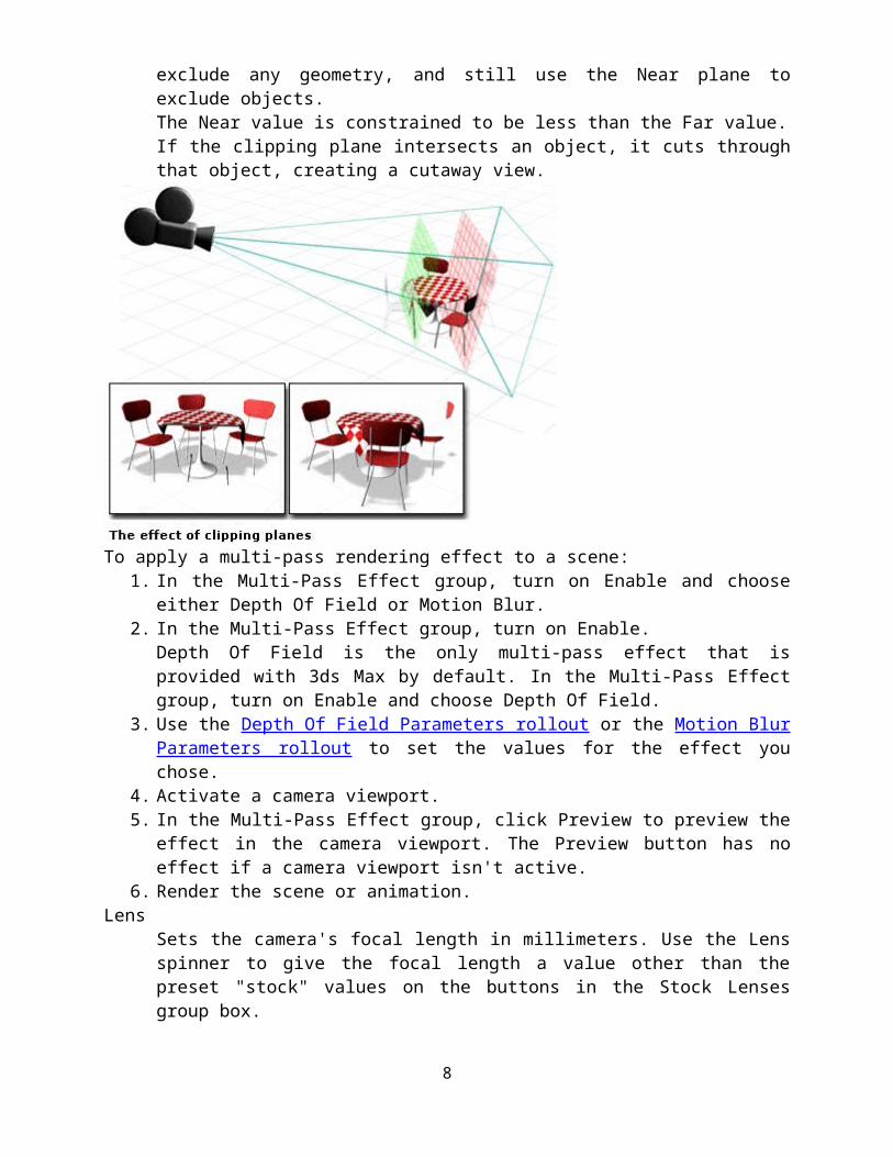
3. Set the Far Clip value to position the far clipping plane. Objects farther from the camera than the Far distance are not visible to the camera and aren't rendered.You can set the Near clipping plane close to the camera so that it doesn't exclude any geometry, and still use the Far plane to exclude objects. Similarly, you can set the Far clipping plane far enough from the camera that it doesn't exclude any geometry, and still use the Near plane to exclude objects.The Near value is constrained to be less than the Far value.
6
If the clipping plane intersects an object, it cuts through that object, creating a cutaway view.
To apply a multi-pass rendering effect to a scene:1. In the Multi-Pass Effect group, turn on Enable and choose either Depth Of Field or
Motion Blur. 2. In the Multi-Pass Effect group, turn on Enable.
Depth Of Field is the only multi-pass effect that is provided with 3ds Max by default. In the Multi-Pass Effect group, turn on Enable and choose Depth Of Field.
3. Use the Depth Of Field Parameters rollout or the Motion Blur Parameters rollout to set the values for the effect you chose.
4. Activate a camera viewport. 5. In the Multi-Pass Effect group, click Preview to preview the effect in the camera
viewport. The Preview button has no effect if a camera viewport isn't active.6. Render the scene or animation.
LensSets the camera's focal length in millimeters. Use the Lens spinner to give the focal length a value other than the preset "stock" values on the buttons in the Stock Lenses group box.Changing the Aperture Width value on the Render Setup dialog also changes the value in the Lens spinner field. This doesn't change the view through the camera, but it does change the relationship between the Lens value and the FOV value, as well as the aspect ratio of the camera's cone.
FOV Direction flyout Lets you choose how to apply the field of view (FOV) value:
Horizontal(The default.) Applies the FOV horizontally. This is the standard way to set and measure the FOV.
VerticalApplies the FOV vertically. DiagonalApplies the FOV diagonally, from one corner of the viewport to the
other.FOV
Determines how wide an area the camera views (field of view). When FOV Direction is horizontal (the default), the FOV parameter directly sets the arc of the camera's horizon,
7
measured in degrees. You can also set the FOV Direction to measure FOV vertically or diagonally.You can also adjust the field of view interactively in a camera viewport by using the FOV button.
Orthographic Projection When on, the camera view looks just like a User view. When off, the camera view is the standard perspective-like view. While Orthographic Projection is in effect, the viewport navigation buttons behave as they ordinarily do, except for Perspective. Perspective function still moves the camera and changes the FOV, but the Orthographic Projection cancels the two out, so you don't see any change until you turn off Orthographic Projection.
Stock Lenses group15mm, 20mm, 24mm, 28mm, 35mm, 50mm, 85mm, 135mm, 200mm These preset values set the camera's focal length in millimeters.Type Changes the camera's type from a Target camera to a Free camera, and vice versa.Show Cone Displays the cone (actually a pyramid) defined by a camera's field of view. The cone appears in the other viewports but does not appear in a camera viewport.Show Horizon Displays the horizon line. A dark gray line appears at the level of the horizon in the camera's viewport.Environment Ranges groupNear Range and Far Range
Determine the near and far range limits for the atmospheric effects set on the Environment panel. Objects between the two limits fade between the Far % and Near % values.
Show Displays rectangles within the camera's cone to show the Near and Far range settings.
8
Clipping Planes groupSets options to define clipping planes. In viewports, clipping planes are displayed as red rectangles (with diagonals) within the camera's cone.Clip Manually
Turn on to define clipping planes.When Clip Manually is off, geometry closer to the camera than 3 units is not displayed. To override this, use Clip Manually.
Near Clip and Far Clip Sets near and far planes. Objects closer than the near clipping plane or farther than the far clipping plane are invisible to the camera. The limit of the Far Clip value is 10 to the power of 32.With manual clipping on, the near clipping plane can be as close to the camera as 0.1 unit.
Multi-Pass Effect group
9

These controls let you assign a depth-of-field or motion blur effect to the camera. When generated by a camera, these effects generate blurring by rendering the scene in multiple passes, with offsets. They increase rendering time.Enable
When on, previewing or rendering uses the effect. When off, the effect is not rendered.Preview
Click to preview the effect in an active camera viewport. This button has no effect if the active viewport is not a camera view.
Effect drop-down list Lets you choose which multi-pass effect to generate, Depth Of Field or Motion Blur. These effects are mutually exclusive. Default=Depth Of Field.This list also lets you choose Depth of Field (mental ray), which lets you use the mental ray renderer's depth of field effect.
Render Effects Per Pass When on, applies rendering effects, if any are assigned, to each pass of the multi-pass effect (depth of field or motion blur). When off, applies rendering effects only after the passes that generate the multi-pass effect. Default=off.Turning off Render Effects Per Pass can improve the render time for multi-pass effects.
Target Distance With a free camera, sets a point to use as an invisible target so that you can orbit a camera around that point. With a target camera, indicates the distance between the camera and its target.
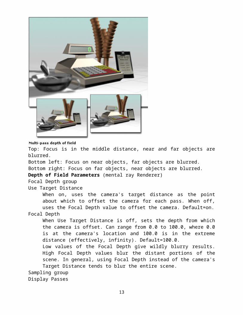
Multi-Pass Depth of Field Parameters for CamerasCameras can generate depth-of-field effects. Depth of field is a multi-pass effect. You turn it on in the Parameters rollout for cameras. Depth of field simulates a camera's depth of field by blurring areas of the frame at a distance from the camera's focal point (that is, its target or target distance).
10

Top: Focus is in the middle distance, near and far objects are blurred.Bottom left: Focus on near objects, far objects are blurred.Bottom right: Focus on far objects, near objects are blurred.Depth of Field Parameters (mental ray Renderer)Focal Depth groupUse Target Distance
When on, uses the camera's target distance as the point about which to offset the camera for each pass. When off, uses the Focal Depth value to offset the camera. Default=on.
Focal Depth When Use Target Distance is off, sets the depth from which the camera is offset. Can range from 0.0 to 100.0, where 0.0 is at the camera's location and 100.0 is in the extreme distance (effectively, infinity). Default=100.0.Low values of the Focal Depth give wildly blurry results. High Focal Depth values blur the distant portions of the scene. In general, using Focal Depth instead of the camera's Target Distance tends to blur the entire scene.
Sampling groupDisplay Passes
When on, the rendered frame window displays the multiple rendering passes. When off, the frame window displays only the final result. This control has no effect on previewing depth of field in camera viewports. Default=on.
Use Original Location When on, the first rendering pass is in the camera's original location. When off, the first rendering pass is offset like all subsequent passes. Default=on.
Total Passes The number of passes used to generate the effect. Increasing this value can increase the effect's accuracy, but at a cost of rendering time. Default=12.
11

Sample Radius The radius by which the scene is shifted to generate blurriness. Increasing this value increases the overall blurriness of the effect. Decreasing it reduces the blurriness. Default=1.0.
Sample Bias Weights the blurring toward or away from the Sample Radius. Increasing this value increases the magnitude of depth-of-field blurring, giving a more even effect. Decreasing it decreases the magnitude, giving a more random effect. Can range from 0.0 to 1.0. Default=0.5.
Pass Blending groupThe multiple depth-of-field passes are blended by dithering, which you can control by the parameters in this group.These controls apply only to renderings of the depth-of-field effect, not to previews in viewports.Normalize Weights
Passes are blended with random weighting to avoid artifacts such as streaking. When Normalize Weights is on, the weights are normalized, giving a smoother result. When off, the effect is a bit sharper but usually grainier. Default=on.
Dither Strength Controls how much dithering is applied to the rendered passes. Increasing this value increases the amount of dithering, and can make the effect grainier, especially at the edges of objects. Default=0.4.
Tile Size Sets the size of the pattern used in dithering. This value is a percentage, where 0 is the smallest tile, and 100 is the largest. Default=32.
Scanline Renderer Params groupThese controls let you disable antialiasing or antialias filtering when you render the multi-pass scene. Disabling these rendering passes can improve render time.These controls apply only to renderings of the depth-of-field effect, not to previews in viewports.Disable Filtering
When on, disables the filtering pass. Default=off.Disable Antialiasing
When on, disables antialiasing. Default=off.Multi-Pass Motion Blur Parameters for Cameras (Default Scanline Renderer rollout)Cameras can generate motion blur effects. Motion blur is a multi-pass effect. You turn it on in the Parameters rollout for cameras. Motion blur simulates the motion blur of a camera by offsetting rendering passes based on movement in the scene.
12
Above: Motion blur applied to wings of the flying dragonBelow: Multiple passes appear in successive refreshes of the rendered frame window.Motion Blur ParametersSampling groupDisplay Passes
When on, the rendered frame window displays the multiple rendering passes. When off, the frame window displays only the final result. This control has no effect on previewing motion blur in camera viewports. Default=on.
Total Passes The number of passes used to generate the effect. Increasing this value can increase the effect's accuracy, but at a cost of rendering time. Default=12.
Duration (frames) The number of frames in the animation to which the motion blur effect will be applied. Default=1.0.
Bias Changes the blurring so that it appears to derive more from frames before or after the current frame. Range=0.01 to 0.99. Default=0.5.By default, the blurring comes equally from frames before and after the current frame; that is, a blurred object appears at the center of the blurred area. This is the closest to what an actual camera would capture. Increasing the Bias value moves the blurring behind the blurred object, in relation to its direction of motion. Decreasing it moves the blurring in front of the blurred object.Extreme values move most of the blurring very close to the blurred object, which makes it difficult to see. For best results, use intermediate Bias values in the range 0.25 to 0.75.
Pass Blending groupThe multiple motion blur passes are blended by dithering, which you can control by the parameters in this group.
13

These controls apply only to renderings of the motion blur effect, not to previews in viewports.Normalize Weights
Passes are blended with random weighting to avoid artifacts such as streaking. When Normalize Weights is on, the weights are normalized, giving a smoother result. When off, the effect is a bit sharper but usually grainier. Default=on.
Dither Strength Controls how much dithering is applied to the rendered passes. Increasing this value increases the amount of dithering, and can make the effect grainier, especially at the edges of objects. Default=0.4.
Tile Size Sets the size of the pattern used in dithering. This value is a percentage, where 0 is the smallest tile, and 100 is the largest. Default=32.
Scanline Renderer Params groupThese controls let you disable antialiasing or antialias filtering when you render the multi-pass scene. Disabling these rendering passes can improve render time.These controls apply only to renderings of the motion blur effect, not to previews in viewports.Disable Filtering
When on, disables the filtering pass. Default=off.Disable Antialiasing
When on, disables antialiasing. Default=off.Walkthrough AssistantThe Walkthrough Assistant lets you easily create a predefined walkthrough animation of your scene by placing a camera on a path and setting the height, turning the camera and viewing a preview. This feature is available from the Animation Menu.To create a Walkthrough camera:
1. On the Animation menu, choose Walkthrough Assistant. The Walkthrough Assistant floater is displayed.
2. On the Main Controls rollout, click the Create New Camera button. 3ds Max creates a free camera named Walkthrough_Cam01, and displays the new camera in the viewports. The camera is also listed by name in the Cameras list.If the camera is not visible in a viewport, you might need to zoom out to see it.
To set the camera path:1. After 3ds Max creates the camera, create a path in the scene using a spline shape or a
NURBS curve.1. In the Path Control group, click Pick Path, then click the path you created. 2. Click (Play Animation) or scrub the time slider to see the camera move along the path. 3. Activate the Perspective viewport, then in the Cameras group, click the Set Viewport to
Camera button. Now you can see what the camera sees.You will probably need to adjust the camera height and tilt at this point.
To adjust the camera height and tilt:1. In the Path Control group, turn on Move Path To Eye Level. 3ds Max sets the path to the
height specified for Eye Level. 2. Use the numerical height spinner to set the desired height. The path moves in the
viewports in real time. You can use (Select And Move) to place the path at the desired height, if you find this more convenient than entering a value.
14

3. Activate the Top viewport. On the View Controls rollout, move the slider in the Turn Head group to turn the camera toward an object in the scene that you want the camera to view.
4. Use the numerical spinner for Head Tilt Angle to change the angle of the camera.1. Play the animation or scrub the time slider to see how the camera presents the scene.
To adjust the camera controls:1. In the Advanced Controls rollout, use the numerical spinner to change the Field Of View.
If you want less of the scene to be seen, decrease the Field Of View setting. Conversely, increase the Field Of View if you want more of the scene to appear.
2. Set the Target Distance to the range at which you want objects to be seen clearly in focus.To animate the camera tilting and turning:
1. Move the time slider to Frame 0. 2. Turn on (Auto Key). 3. Slide the Turn Head control to turn the camera left, center, or right. If desired, adjust the
Head Tilt Angle control up or down. 4. Use the time slider to advance the camera to the next place where you want to turn or tilt
the camera differently. 5. When you've completed setting rotation keys for the camera, play the animation. 6. If you are not pleased with the results, click the Views Control rollout Remove All Head
Animation button to quickly delete all the head-movement keys. To quickly reset the camera head position, click the Reset Eyes Level button.
To render a preview: On the Render Preview rollout, click the Render Preview button to see a preview of what
the camera sees.To create a targeted camera:
1. On the Main Controls rollout, select Targeted. 2. Click the Create New Camera button. A camera and its target are placed in the scene. The
camera is named incrementally and added to the Camera list. The Targeted toggled is also turned on in the Cameras group.
1. Click the Pick Path button and select a spline. 2. In the Look-At-Camera rollout, click Object. 3. Click the Pick Target Object button, and select an object on which you want the camera to
focus. The target is moved to the object. If you had selected a path, the target would move to the path.
4. Click the Set Viewport to Camera button. The viewport label changes to reflect the current camera name and displays what the Targeted camera sees.
5. Click (Play Animation) or scrub the time slider to view the animation.Camera Creation groupCreate New Camera
Automatically creates a free or targeted camera in the scene. Cameras are named Walkthrough_Cam followed by a sequence number.
Free (The default.) When chosen, the new camera is a free camera. Targeted When chosen, the new camera is a target camera.
Cameras groupCameras list
Lists cameras in the scene by name.Targeted
15

Controls whether a selected camera in the Camera list is targeted or free. Turning on Targeted for a free camera will change it to targeted; turning it off for a targeted camera will change it to a free camera. Default=off.
Set Viewport to Camera Changes the active viewport to a camera viewport.
Path Control groupPick Path
Click this button to select a path in the scene. After you select a path, the button label changes to the object's name. Click the Clear Path button to disassociate the camera from the selected path.
Move Path to Eye Level When turned on, moves the path to the height set for Eye Level. When turned off, it moves the path to its original height when created.
Eye Level Allows you to specify a precise height of the path that either raises or lowers the camera view.
Render Preview rolloutClick to Render Preview
Renders a preview. The preview appears in the small window in the Walkthrough Assistant floater.
View Controls rolloutThis rollout only displays if a free camera is created or selected.Turn Head groupTurn Head Slider
Rotates the camera head as it moves along the path. This allows you to create the illusion that you are turning your head as you walk through the scene. Choices are Left, Center, Right. To animate the head turning, use the Auto Key button. This creates Z Rotation keys that can be adjusted in Track View.
Head Tilt Angle Rotates the camera as it moves along the path. This creates the illusion that you are tilting your head up or down as you walk through the scene. To animate, use the Auto Key button. This creates X Rotation keys that can be adjusted in Track View.
Reset Eyes Level Constrains the head tilt to be level with the path.
Remove All Head Animation Deletes all key frames created when the Auto Key was enabled.
Look-At-Camera rolloutThis rollout only displays if a targeted camera is created or selected.Look-At-Camera groupPath
When selected, allows you to select a path the camera's target will use.Object
When selected, allows you to select an object the camera's target will use.Pick Target Path
Press this button to select a path or object in the scene. Click the Clear Path button to disassociate the camera's target from the selected path or object.
Advanced Controls rolloutCamera Controls groupField of View
16

Adjusts the amount of the scene visible in the viewport and the perspective flare. Extreme values will create distortion in the viewport.
Target Distance Sets the distance the target is from the camera. This controls the size of the camera icon in the viewport. In a free camera, the point the camera orbits around is controlled by the target distance.
Path Controls group Constant Speed
Turn this on to maintain a constant speed along a path. When off, the velocity of the object along the path varies depending on the distance between the vertices on the path.
Follow Path When this is turned on, the camera stays perpendicular to the path. When this is turned off, the camera does not turn as it follows along the path.
Camera Match UtilityThe Camera Match utility uses a bitmap background photo and five or more special "CamPoint" objects to create or modify a camera so that its position, orientation, and field-of-view matches that of the camera that originally created the photo.ProceduresThe general process to follow in using Camera Match is described in the following procedures.To use camera matching:
1. Load a bitmap as a background for the renderer. 2. Load a bitmap as a background for the viewport. 3. Identify on the bitmap at least five features that will be used for the match. These should
be objects or corners of objects in the scene that can be identified and tracked. They should remain visually throughout the scene, and should not change their shape too much or they won’t work.
4. Create CameraPoints, which are helper objects found in these locations: Create panel (Helpers) Camera Match Object Type rollout CamPoint, and Create menu Helpers Camera Point. You must have accurate measurements of distances between at least five features in your scene, which can’t be all on a single plane. Try to use points that are distributed throughout the scene rather than features that are all clustered in the front or back. This will give the most accurate results.
5. Position these CameraPoints to correspond to points in your photo. You can use the Transform Type-In to position the points in the correct locations in 3D space.
6. Use the Camera Match utility to assign the CameraPoints to pixel locations on the bitmap. 7. Choose Create Camera and a camera is created to match the one that took the picture. If
there are errors and the camera cannot be created, readjust the point positions in 3D space, and reassign them to the bitmap. It’s easy to make a mistake doing either, but once you get it right the match should work.
To establish the bitmap background for the renderer:1. Reset 3ds Max, and enlarge the Perspective viewport to full screen. 2. From the Rendering menu. choose Environment. 3. In the Common Parameters rollout, under Environment Map, click the gray box marked
None. This launches the Material/Map Browser. 4. Be sure to set Browse From to New; if it isn’t set already, then choose Bitmap from the
list and click OK. The Select Bitmap Image File dialog appears. 5. Navigate and select the appropriate bitmap and then choose Open. Use Map is turned on
automatically.
17
6. Render the viewport to verify that the background appears in the rendering. Press Shift+Q to render.
To establish the bitmap background to display in the viewport:1. Choose Views menu Viewport Background. This opens the Viewport Background dialog2. In the Background Source group, click Files. This launches the Select Background Image
dialog. 3. Navigate and select the appropriate bitmap and then choose Open. 4. Set Aspect Ratio to Match Bitmap. 5. Make sure Display Background is turned on, and then choose OK. The background
appears in the viewport.To create CamPoint objects:
1. Do one of the following: o On the Create panel, turn on (Helpers), choose Camera Match from the drop-down
list, then on the Object Type rollout, turn on CamPoint. o Choose Create menu Helpers CamPoint.
2. Create your CamPoint objects anywhere in the scene, and reselect each of them to enter their absolute coordinates using the Transform Type-In.
3. Open the Keyboard Entry rollout. 4. Enter the coordinates of the first CamPoint object (0,0,0), click the Create button, and
then enter the name in the name field.5. Repeat the above steps for the remaining CamPoint objects.
You now have the CamPoint objects occupying real-world coordinate positions that correspond to the structure in the bitmap image. The last sequence of steps involves using the Camera Match utility to specify the screen coordinate points, one for each CamPoint object, and generating a camera position based on the data.To use the Camera Match utility:
1. On the Utilities panel, click the Camera Match button. The Camera Match utility appears, listing the CamPoint objects.
2. Select the first CamPoint object and click the Assign Position button. 3. Place the cursor over the corresponding feature in the bitmap and click.
A small, red cross appears.4. If the dot is not in the right position, you can either click again with the mouse or adjust
the Input Screen Coordinates to tweak its position. 5. Select the second object in the list, and repeat steps 3 and 4. 6. Repeat for all the points. By setting the red crosses, you’ve indicated the X and Y pixel
position on the bitmap and correlated it with each CamPoint as it exists in 3D space. 7. Once you have all of the points set, click the Create Camera button.
A camera is created in the scene based on the location of the CamPoint objects and the specifications of the screen coordinates points.
8. Press C to switch the Perspective view to that of the new camera.CamPoint Info rolloutList window
Displays a list of the CamPoint helper objects in the scene. You select the CamPoint objects from this list to assign screen coordinate points. Note that if you select a CamPoint object in the viewport, it‘s highlighted in this list as well.
Input Screen Coordinates X/Y
Fine-tunes the position of the screen coordinate points in 2D space.Use This Point
18

Turns off a specific coordinate point without deleting it. Select the corresponding CamPoint in the list, and then turn off Use This Point. This feature is typically used for troubleshooting when the Current Camera Error is too high (greater than five, for example).
Assign Position Click a location on the viewport bitmap to place a screen coordinate point visually against the background image. The point you place corresponds to the currently selected CamPoint object. After activating the Assign Position button, select a CamPoint object from the list, and then click in the viewport at a position on the bitmap background that corresponds with where the associate CamPoint object should be in the 3D scene. After repeating this process with each CamPoint object in the list, you can click the Create Camera button to create a camera that matches the placed coordinates with their associate CamPoint objects.
Camera Match rolloutCreate Camera
Creates a camera in the scene whose position, orientation, and field of view is based on the current location of the CamPoint helpers and the assigned screen coordinate points.
Modify Camera Modifies the position, orientation and FOV of an existing, selected camera based on the CamPoint helpers and assigned screen coordinate points.
Iterations Maximum number of iterations used to calculate the camera position. Default is 500, though a stable solution is usually found in less than 100 iterations.
Freeze FOV Prevents the FOV (field of view) of the camera from being changed when using the Create Camera or Modify Camera buttons. Use if the FOV of the camera that took the photograph is known and you want to preserve it.
Current Camera Error Displays the total error that remains between the placed screen coordinate points, the CamPoint helpers, and the camera position after the final computation. The calculations involved in the camera match are seldom perfect. A good error range is about 0 to 1.5.
Close Exits the Camera Match utility.
19