camcon rk512 data table - digitronic · the different interfaces and the procedure of the...
TRANSCRIPT
The tabular programming interface
of the digital cam control
CamCon DC16/40/50/90/190/300 and 1756-DICAM
Digitronic Automationsanlagen GmbH Auf der Langwies 1 D - 65510 Hünstetten-Wallbach Phone +49 6126 9453-0 Fax -42
Internet: http://www.digitronic.com E-Mail: [email protected]
Digitronic CamCon Data Table for Automationsanlagen GmbH DC16/40/51/90/190/300 and 1756-DICAM
Edition: 24.07.2017 Page: 2/35
Please note
This manual is state of the art of the CamCon dated 3/2016. The company Digitronic Automationsanlagen GmbH reserves the right to make changes which would improve the quality or functionality of the device at any time without prior notice. Even though the operating instructions are issued with extreme care, it is not possible to avoid all errors that might occur. We appreciate any indications regarding possible errors in the operating instructions.
Update You will also find the latest version of this manual on the Internet under http://www.digitronic.com as a PDF file.
Qualified staff Commissioning and operation must only be performed by qualified staff. Qualified staff are employees, who have the right to commission, earth and mark devices, systems and circuits according to the standards of the safety technology.
Liability (1) The seller is liable for any damages for which he or the right holder is responsible amounting to the selling price. A liability for lost profit, default of savings, indirect damages and subsequent damages is excluded. (2) The above limitations of liability do not apply for warranted qualities and damages which are based on intent or gross negligence.
Protection The CamCon and this manual are copyright. All rights reserved. Neither the CamCon nor this document may be copied, photocopied, reproduced, translated or transmitted in parts or as a whole on any electronic media or in machine-readable for, without prior written approval of the company Digitronic Automationsanlagen GmbH.
Note: CamCon is a registered trademark of the company Digitronic Automationsanlagen GmbH.
Note: The device fulfils the standards: DIN EN 61000-6-2:2006-03,61000-4-2:2009-12,61000-4-4:2010-11,61000-4-5:2007-06,61000-4-8:2010-11 and DIN EN 55011:2011-04 and RoHS 2 (2011/65/EU).
(c) Copyright 1992 - 2017 / File: RK512E.DOC
Digitronic Automationsanlagen GmbH Auf der Langwies 1
D-65510 Hünstetten - Wallbach Phone (+49)6126/9453-0 Fax (+49)6126/9453-42
Internet: http://www.digitronic.com / E-Mail: [email protected]

Digitronic CamCon Data Table for Automationsanlagen GmbH DC16/40/51/90/190/300 and 1756-DICAM
Edition: 24.07.2017 Page: 3/35
Table of contents
1. General Information .............................................................................................................................. 5
2. Interfaces .............................................................................................................................................. 5 2.1. Serial interface .................................................................................................................................. 6 2.1.1. RS232 connection .......................................................................................................................... 6 2.1.2. RS485 connection .......................................................................................................................... 6 2.1.2.1. Protocol settings of the interface on the CamCon ...................................................................... 6 2.1.2.2. Procedure of the communication ................................................................................................ 7 2.1.2.2.1. The RK512 procedure .............................................................................................................. 7 2.1.2.2.2. The 3964(R) protocol ............................................................................................................... 8 2.2. Profibus interface via CamCon CP16/P/IO ....................................................................................... 9 2.2.1. Setting of the CamCon on Profibus ................................................................................................ 9 2.2.2. Procedure of the communication ................................................................................................... 9 2.3. S7 300 interface via backplane bus for CamCon DC300 ............................................................... 10 2.3.1. Projecting the S7 CPU for CamCon DC300 ................................................................................. 10 2.3.2. Procedure of the communication ................................................................................................. 10 2.4. ControlLogix interface via backplane bus for CamCon 1756-DICAM ............................................. 11 2.4.1. Projecting the ControlLogix CPU for CamCon 1756-DICAM ....................................................... 11 2.4.2. Procedure of the communication ................................................................................................. 11 2.5. EthernetIP interface for CamCon DC190 ........................................................................................ 12 2.5.1. Projecting the ControlLogix CPU for CamCon DC190 EthernetIP .............................................. 12 2.5.2. Procedure of the communication ................................................................................................. 12 2.6. OP interface or user menu of the Digitronic programming interface ............................................... 13 2.6.1. Projecting the programming interface .......................................................................................... 13 2.6.2. Procedure of the communication ................................................................................................. 13
3. Assignment of the data tables of the CamCon ................................................................................... 14 3.1. Data area 1..200 - cam and dead time programming / reading ...................................................... 14 3.2. Data area 201 - reading the status, setting the actual value and the program number .................. 15 3.3. Data area 202 - Reading status, inputs, outputs and flags ............................................................. 17 3.4. Data area 203 - Setting the system parameter ............................................................................... 21 3.4.1. Data area 203 Data word 0..7 - Setting the position sensor parameters ..................................... 23 3.4.1.1. Data word 0..7 - Special position sensor SSI ............................................................................ 24 3.4.1.2. Data word 0..7 - Special position sensor parallel ...................................................................... 24 3.4.1.3. Data word 0..7 - Special position sensor incremental ............................................................... 24 3.4.1.4. Data word 0..7 - Special position sensor (MULTI)turn .............................................................. 24 3.4.1.5. Data word 0..7 - Special position sensor (P)hase - (L)ock - (L)oop .......................................... 25 3.4.1.6. Data word 0..7 - Special position sensor Timer in milliseconds ................................................ 25 3.4.1.7. Data word 0..7 - Special position sensor AG615 with exploit or turns ...................................... 25 3.4.1.8. Data word 0..7 - special position sensor speed (SIM)ulation .................................................... 25 3.4.1.9. Data word 0..7 - Special position sensor (HIPER)face ............................................................. 26 3.4.1.10. Data word 0..7 - Special position sensor SSI2 for advanced settings .................................... 26 3.5. Data area 204 - Parameterising analogous cam outputs ................................................................ 27 3.6. Data area 205 - Device configuration, Complete deletion, Error acknowledgement, EE-Lock, CP1627 3.7. Data area 206..209 - Target values in the PLC logic module ......................................................... 28 3.7.1. Data area 206 - Target values in the area O of the PLC logic module ........................................ 28 3.7.2. Data area 207 - Target values in the area P of the PLC logic module ........................................ 28 3.7.3. Data area 208 - Target values in the area M of the PLC logic module ........................................ 28 3.7.4. Data area 209 - Target values in the area X of the PLC logic module ........................................ 28 3.8. Data area 210..213 - Actual values in the PLC logic module .......................................................... 29 3.8.1. Data area 210 - Actual values in the area O of the PLC logic module ........................................ 29 3.8.2. Data area 211 - Actual values in the area P of the PLC logic module ......................................... 29 3.8.3. Data area 212 - Actual values in the area M of the PLC logic module ........................................ 29 3.8.4. Data area 213 - Actual values in the area X of the PLC logic module ......................................... 29
Digitronic CamCon Data Table for Automationsanlagen GmbH DC16/40/51/90/190/300 and 1756-DICAM
Edition: 24.07.2017 Page: 4/35
3.9. Data area 214 - Multi or multiple cam programming ....................................................................... 30 3.10. Data area 215 - Reading envelope curve of the analogue monitoring ......................................... 30 3.11. Data area 216 - Programming and reading the link in the PLC logic module ............................... 31 3.12. Data area 217 - Programming the IO Router ................................................................................ 32 3.13. Data area 217 from DW256 on - Extended hardware configuration of the CamCon DC190 ....... 33 3.14. Data area 218 - Direct EE-Prom data memory access ................................................................. 34 3.15. Data area 219 - Adjusting NLT table ............................................................................................. 34 3.16. Data area 221 - WZS - Setting digital monitoring ......................................................................... 34 3.17. Data area 222 - WZS - Setting analogous monitoring .................................................................. 34 3.18. Data area 223 - Trend function ..................................................................................................... 34 3.19. Data area 241..254 - Programming / reading analogous cams 1..14 ........................................... 35
Digitronic CamCon Data Table for Automationsanlagen GmbH DC16/40/51/90/190/300 and 1756-DICAM
Edition: 24.07.2017 Page: 5/35
1. General Information All system, cam, dead time and PLC parameters of the CamCon DC16, 40, 50/51, 90, 190, 300 and 1756-DICAM cam gears are filed in a database and can be read or written. The table is divided into 255 data areas (data block) of 256 words with 32Bit (DINT) each. Several interfaces are available in order to be able to read or write the contents of the table. The different interfaces and the procedure of the communication are described in this manual. In chapter "3. Assignment of the data tables of the CamCon" on page 14 the entries or parameters of the table are being described. They are essentially the same for all CamCon devices. 2. Interfaces The devices of the CamCon series make an abundance of different interfaces available. These are: * Serial interface RS232.
* Serial interface RS485.
* Serial interface TTY 20mA.
* Profibus DP interface.
* System backplane bus interface Siemens S5 - 115U.
* System backplane bus interface Siemens S7 - 300.
* System backplane bus interface Rockwell ControlLogix 1756.
* Ethernet WEB - Server interface.
* EthernetIP.
* OP function or user menu of the Digitronic programming interface.
Digitronic CamCon Data Table for Automationsanlagen GmbH DC16/40/51/90/190/300 and 1756-DICAM
Edition: 24.07.2017 Page: 6/35
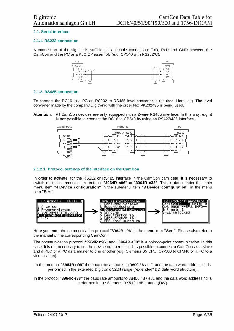
2.1. Serial interface . 2.1.1. RS232 connection A connection of the signals is sufficient as a cable connection: TxD, RxD and GND between the CamCon and the PC or a PLC CP assembly (e.g. CP340 with RS232/C).
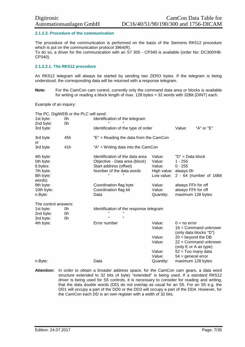
2.1.2. RS485 connection To connect the DC16 to a PC an RS232 to RS485 level converter is required. Here, e.g. The level converter made by the company Digitronic with the order No: PK232485 is being used. Attention: All CamCon devices are only equipped with a 2-wire RS485 interface. In this way, e.g. it
is not possible to connect the DC16 to CP340 by using an RS422/485 interface.
CamCon DC16 PK232485 PC
2.1.2.1. Protocol settings of the interface on the CamCon In order to activate, for the RS232 or RS485 interface in the CamCon cam gear, it is necessary to switch on the communication protocol "3964R n96" or "3964R e38". This is done under the main menu item "4 Device configuration" in the submenu item "3 Device configuration" in the menu item "Ser:".
Here you enter the communication protocol "3964R n96" in the menu item "Ser:". Please also refer to the manual of the corresponding CamCon.
The communication protocol "3964R n96" and "3964R e38" is a point-to-point communication. In this case, it is not necessary to set the device number since it is possible to connect a CamCon as a slave and a PLC or a PC as a master to one another (e.g. Siemens S5 CPU, S7-300 to CP340 or a PC to a visualisation). In the protocol "3964R n96" the baud rate amounts to 9600 / 8 / n /1 and the data word addressing is
performed in the extended Digitronic 32Bit range ("extended" DD data word structure).
In the protocol "3964R e38" the baud rate amounts to 38400 / 8 / e /1 and the data word addressing is performed in the Siemens RK512 16Bit range (DW).
Digitronic CamCon Data Table for Automationsanlagen GmbH DC16/40/51/90/190/300 and 1756-DICAM
Edition: 24.07.2017 Page: 7/35
2.1.2.2. Procedure of the communication The procedure of the communication is performed on the basis of the Siemens RK512 procedure which is put on the communication protocol 3964(R). To do so, a driver for the communication with an S7 300 - CP340 is available (order No: DC300/HB-CP340). 2.1.2.2.1. The RK512 procedure An RK512 telegram will always be started by sending two ZERO bytes. If the telegram is being understood, the corresponding data will be returned with a response telegram. Note: For the CamCon cam control, currently only the command data area or blocks is available
for writing or reading a block length of max. 128 bytes = 32 words with 32Bit (DINT) each. Example of an inquiry: The PC, DigiWEB or the PLC will send: 1st byte: 0h Identification of the telegram 2nd byte: 0h " " 3rd byte: Identification of the type of order Value: "A" or "E" 3rd byte 45h "E" = Reading the data from the CamCon or 3rd byte 41h "A" = Writing data into the CamCon 4th byte: Identification of the data area Value: "D" = Data block 5th byte: Objective - Data area (block) Value: 1 - 255 6.bytes: Start address (offset) Value: 0 - 255 7th byte: Number of the data words High value: always 0h 8th byte: " " Low value: 2 - 64 (number of 16Bit words) 9th byte: Coordination flag byte Value: always FFh for off 10th byte: Coordination flag bit Value: always FFh for off n.Byte: Data Quantity: maximum 128 bytes The control answers: 1st byte: 0h Identification of the response telegram 2nd byte: 0h " " 3rd byte: 0h " " 4th byte: Error number Value: 0 = no error Value: 16 = Command unknown (only data blocks "D") Value: 20 = beyond the DB Value: 22 = Command unknown (only E or A as type) Value: 52 = Too many data Value: 54 = general error n.Byte: Data Quantity: maximum 128 bytes Attention: In order to obtain a broader address space, for the CamCon cam gears, a data word
structure extended to 32 bits (4 byte) "extended" is being used. If a standard RK512 driver is being used for S5 controls, it is necessary to consider for reading and writing, that the data double words (DD) do not overlap as usual for an S5. For an S5 e.g. the DD1 will occupy a part of the DD0 or the DD3 will occupy a part of the DD4. However, for the CamCon each DD is an own register with a width of 32 bits.

Digitronic CamCon Data Table for Automationsanlagen GmbH DC16/40/51/90/190/300 and 1756-DICAM
Edition: 24.07.2017 Page: 8/35
2.1.2.2.2. The 3964(R) protocol The 3964(R) protocol will be used for the point-to-point communication between the PLC controls and the PCs. For most PLC controls and IPC, they will be available as communication processors or Windows DLL drivers. If you need to integrate the 3964(R) protocol into your own control, please follow a short description: General telegram structure in HEX:
PC, PLC or DigiWEB will send CamCon or a foreign system will answer
0x02
0x10
Data (RK512 telegram request) Attention: If the data include the character 0x10 it needs to be sent twice!
0x10, 0x03, BCC
0x10
PC, PLC or DigiWEB will answer: CamCon or foreign system will send:
0x02
0x10
Data (RK512 telegram acknowledgement) Attention: If the data include the character 0x10, it will be sent twice!
0x10, 0x03, BCC
0x10
BCC: The checksum BCC is the Exclusive - Or - Sum of the data and of the characters 0x10
and 0x03. A double 0x10 character in the data will be added to the checksum. Error: If an error is determined in the protocol, the corresponding station will answer with the
character 0x15 for a negative acknowledgement. Timeout: The timeout of the communication amounts to 220ms.

Digitronic CamCon Data Table for Automationsanlagen GmbH DC16/40/51/90/190/300 and 1756-DICAM
Edition: 24.07.2017 Page: 9/35
2.2. Profibus interface via CamCon CP16/P/IO The CamCon communication processor CP16/P/IO is required for the Profibus. Please refer to the manual of the CamCon CP16/P/IO module.
CamCon Highspeed IO Transfer (<1ms)
CamCon Nockenschaltwerk CamCon CP16/P/IOSSI Schnittstelle
CamCon - Hardware
Aus - u. Eingänge
PC-Schnittstelle
und CamCon Parameter Transfer
Profibus DP
zur SPS
durch das externe Interface.
für Wegmeßsystem
2.2.1. Setting of the CamCon on Profibus To do so, open the submenu"6. Hardware configuration" in the menu "4. Device communication” and set the CP type to Profibus.
If the Profibus on the PLC is set and if the DP addresses are correct, the green LED on the CP16/P/IO needs to be permanently lit. 2.2.2. Procedure of the communication The communication will be controlled by the handling blocks (order No: CP16/HB-S7 or -S5) in the PLC. To do so, a data block is available in the PLC program (in the S7 example of the DB40), which is prepared for taking on data records of the data table or which is provided with examples. Currently, it is possible to transfer max. 44 bytes = 11 words for 32 bits (DINT) each. The data records in the S7 DB40 data blocks are saved as a linked list which indicated the following data records with their length specification (refer to 2nd). One data record consists of: 1. The serial data record number. 2. The number of data words (DINT)(max.11) in the data record. 3. Reading a bit for a data record on or off. 4. Writing a bit for a data record on or off. 5. Table or data area of the CamCon which needs to be read or written. 6. Offset in the table from where the data are positioned. 8. up to 11 words for 32 bits (DINT) each are written or have been read with the data (refer to 2.). 9. Here, the number of the following data record or FFFF for the last data record can be found. The data transfer will be started as soon as the bit PARK, LARK, PRK or LRK will be set in the command word (FB41 parameter "IN_COMMANDS"). The corresponding bit will be reset if the reading or programming is terminated.
Digitronic CamCon Data Table for Automationsanlagen GmbH DC16/40/51/90/190/300 and 1756-DICAM
Edition: 24.07.2017 Page: 10/35
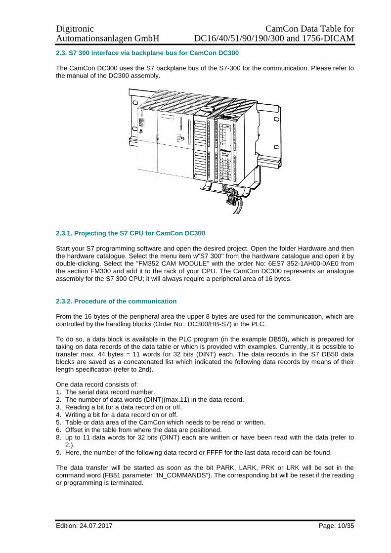
2.3. S7 300 interface via backplane bus for CamCon DC300 The CamCon DC300 uses the S7 backplane bus of the S7-300 for the communication. Please refer to the manual of the DC300 assembly.
2.3.1. Projecting the S7 CPU for CamCon DC300 Start your S7 programming software and open the desired project. Open the folder Hardware and then the hardware catalogue. Select the menu item w"S7 300" from the hardware catalogue and open it by double-clicking. Select the "FM352 CAM MODULE" with the order No: 6ES7 352-1AH00-0AE0 from the section FM300 and add it to the rack of your CPU. The CamCon DC300 represents an analogue assembly for the S7 300 CPU; it will always require a peripheral area of 16 bytes. 2.3.2. Procedure of the communication From the 16 bytes of the peripheral area the upper 8 bytes are used for the communication, which are controlled by the handling blocks (Order No.: DC300/HB-S7) in the PLC. To do so, a data block is available in the PLC program (in the example DB50), which is prepared for taking on data records of the data table or which is provided with examples. Currently, it is possible to transfer max. 44 bytes = 11 words for 32 bits (DINT) each. The data records in the S7 DB50 data blocks are saved as a concatenated list which indicated the following data records by means of their length specification (refer to 2nd). One data record consists of: 1. The serial data record number. 2. The number of data words (DINT)(max.11) in the data record. 3. Reading a bit for a data record on or off. 4. Writing a bit for a data record on or off. 5. Table or data area of the CamCon which needs to be read or written. 6. Offset in the table from where the data are positioned. 8. up to 11 data words for 32 bits (DINT) each are written or have been read with the data (refer to
2.). 9. Here, the number of the following data record or FFFF for the last data record can be found. The data transfer will be started as soon as the bit PARK, LARK, PRK or LRK will be set in the command word (FB51 parameter "IN_COMMANDS"). The corresponding bit will be reset if the reading or programming is terminated.
Digitronic CamCon Data Table for Automationsanlagen GmbH DC16/40/51/90/190/300 and 1756-DICAM
Edition: 24.07.2017 Page: 11/35
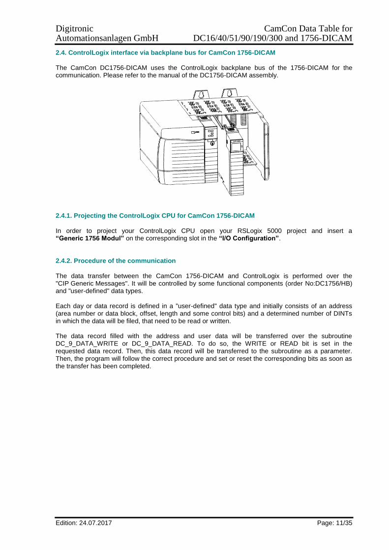
2.4. ControlLogix interface via backplane bus for CamCon 1756-DICAM The CamCon DC1756-DICAM uses the ControlLogix backplane bus of the 1756-DICAM for the communication. Please refer to the manual of the DC1756-DICAM assembly.
2.4.1. Projecting the ControlLogix CPU for CamCon 1756-DICAM In order to project your ControlLogix CPU open your RSLogix 5000 project and insert a “Generic 1756 Modul” on the corresponding slot in the “I/O Configuration”. 2.4.2. Procedure of the communication The data transfer between the CamCon 1756-DICAM and ControlLogix is performed over the "CIP Generic Messages". It will be controlled by some functional components (order No:DC1756/HB) and "user-defined" data types. Each day or data record is defined in a "user-defined" data type and initially consists of an address (area number or data block, offset, length and some control bits) and a determined number of DINTs in which the data will be filed, that need to be read or written. The data record filled with the address and user data will be transferred over the subroutine DC_9_DATA_WRITE or DC_9_DATA_READ. To do so, the WRITE or READ bit is set in the requested data record. Then, this data record will be transferred to the subroutine as a parameter. Then, the program will follow the correct procedure and set or reset the corresponding bits as soon as the transfer has been completed.

Digitronic CamCon Data Table for Automationsanlagen GmbH DC16/40/51/90/190/300 and 1756-DICAM
Edition: 24.07.2017 Page: 12/35
2.5. EthernetIP interface for CamCon DC190
From Software 3/2016 on, the CamCon DC190 can communicate with a ControlLogix 1756 PLC via EthernetIP or LAN.
2.5.1. Projecting the ControlLogix CPU for CamCon DC190 EthernetIP
In order to project your ControlLogix CPU open your RSLogix 5000 project and insert an “ETHERNET-MODULE Generic Ethernet Module” into the "I/O Configuration" and set the IP address as well as the "Connection Parameter".
2.5.2. Procedure of the communication
The data transfer between the CamCon DC190 and ControlLogix is performed over the "CIP Generic Messages". It will be controlled by some functional components (order No. DC190/ETHIP/HB) and "user-defined" data types.
Each day or data record is defined in a "user-defined" data type and initially consists of an address (area number or data block, offset, length and some control bits) and a determined number of DINTs in which the data will be filed, which need to be read or written.
The data record filled with the address and user data will be transferred over the subroutine DC_9_DATA_WRITE or DC_9_DATA_READ.
To do so, the WRITE or READ bit re set in the desired data record.
Then, this data record will be transferred to the subroutine as a parameter. Then, the program will follow the correct procedure and set or reset the corresponding bits as soon as the transfer has been completed.

Digitronic CamCon Data Table for Automationsanlagen GmbH DC16/40/51/90/190/300 and 1756-DICAM
Edition: 24.07.2017 Page: 13/35
2.6. OP interface or user menu of the Digitronic programming interface The OP function uses the standard display and the keyboard of the CamCon DC50/51 for communication. This function facilitates the changing and controlling of system, dead time and variables of the PLC - logic - module to the end customer, without having to interfere in the submenu of the device. By using this function, the risk of an operating error or of a wrong entry will be reduced to a minimum.
2.6.1. Projecting the programming interface For the projecting of the OP function, please refer to the chapter "User menu or OP function” in the manual of the PLC logic module. Here you can read and write the data in the data table by using the variables D-TAB and D-TAB-PRESET. Attention: It is not possible to program any cams by using D-TAB and D-TAB-PRESET. 2.6.2. Procedure of the communication
, , , , , ,
Digitronic CamCon Data Table for Automationsanlagen GmbH DC16/40/51/90/190/300 and 1756-DICAM
Edition: 24.07.2017 Page: 14/35
3. Assignment of the data tables of the CamCon
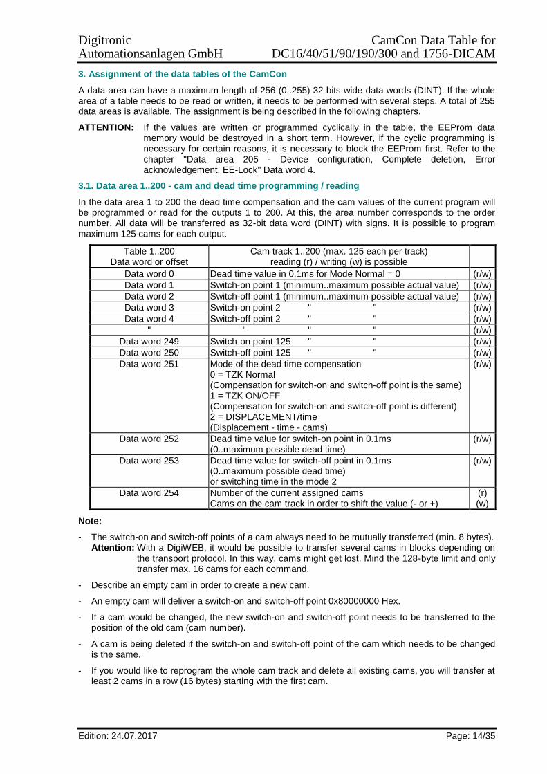
A data area can have a maximum length of 256 (0..255) 32 bits wide data words (DINT). If the whole area of a table needs to be read or written, it needs to be performed with several steps. A total of 255 data areas is available. The assignment is being described in the following chapters.
ATTENTION: If the values are written or programmed cyclically in the table, the EEProm data memory would be destroyed in a short term. However, if the cyclic programming is necessary for certain reasons, it is necessary to block the EEProm first. Refer to the chapter "Data area 205 - Device configuration, Complete deletion, Error acknowledgement, EE-Lock" Data word 4.
3.1. Data area 1..200 - cam and dead time programming / reading
In the data area 1 to 200 the dead time compensation and the cam values of the current program will be programmed or read for the outputs 1 to 200. At this, the area number corresponds to the order number. All data will be transferred as 32-bit data word (DINT) with signs. It is possible to program maximum 125 cams for each output.
Table 1..200 Data word or offset
Cam track 1..200 (max. 125 each per track) reading (r) / writing (w) is possible
Data word 0 Dead time value in 0.1ms for Mode Normal = 0 (r/w)
Data word 1 Switch-on point 1 (minimum..maximum possible actual value) (r/w)
Data word 2 Switch-off point 1 (minimum..maximum possible actual value) (r/w)
Data word 3 Switch-on point 2 " " (r/w)
Data word 4 Switch-off point 2 " " (r/w)
" " " " (r/w)
Data word 249 Switch-on point 125 " " (r/w)
Data word 250 Switch-off point 125 " " (r/w)
Data word 251 Mode of the dead time compensation 0 = TZK Normal (Compensation for switch-on and switch-off point is the same) 1 = TZK ON/OFF (Compensation for switch-on and switch-off point is different) 2 = DISPLACEMENT/time (Displacement - time - cams)
(r/w)
Data word 252 Dead time value for switch-on point in 0.1ms (0..maximum possible dead time)
(r/w)
Data word 253 Dead time value for switch-off point in 0.1ms (0..maximum possible dead time) or switching time in the mode 2
(r/w)
Data word 254 Number of the current assigned cams Cams on the cam track in order to shift the value (- or +)
(r) (w)
Note:
- The switch-on and switch-off points of a cam always need to be mutually transferred (min. 8 bytes). Attention: With a DigiWEB, it would be possible to transfer several cams in blocks depending on
the transport protocol. In this way, cams might get lost. Mind the 128-byte limit and only transfer max. 16 cams for each command.
- Describe an empty cam in order to create a new cam.
- An empty cam will deliver a switch-on and switch-off point 0x80000000 Hex.
- If a cam would be changed, the new switch-on and switch-off point needs to be transferred to the position of the old cam (cam number).
- A cam is being deleted if the switch-on and switch-off point of the cam which needs to be changed is the same.
- If you would like to reprogram the whole cam track and delete all existing cams, you will transfer at least 2 cams in a row (16 bytes) starting with the first cam.

Digitronic CamCon Data Table for Automationsanlagen GmbH DC16/40/51/90/190/300 and 1756-DICAM
Edition: 24.07.2017 Page: 15/35
3.2. Data area 201 - reading the status, setting the actual value and the program number In the data area 201 it is possible to read the status of the device or to set the current program number and the current actual value.
Area 201 Data word or offset
CamCon status reading (r) / writing (w) is possible
Data word 0 Current actual value (r) Set the actual value (w), in doing so, e.g. the message Clear for a Hiperface input will be acknowledged and the actual value with the position of the machine will be synchronised (refer to DB203, DW17).
(r/w)
Data word 1 Speed (r)
Data word 2 Current program number (r) / program change (w) (r/w)
Data word 3 Value of the 1st analogue output (scaled to 16 bits) (r)
Data word 4 Value of the 2nd analogue output (scaled to 16 bits) (r)
Data word 5 Value of the 3rd analogue output (scaled to 16 bits) (r)
Data word 6 Value of the 4th analogue output (scaled to 16 bits) (r)
Data word 7 Value of the 5th analogue output (scaled to 16 bits) (r)
Data word 8 Value of the 6th analogue output (scaled to 16 bits) (r)
Data word 9 Value of the 7th analogue output (scaled to 16 bits) (r)
Data word 10 Value of the 8th analogue output (scaled to 16 bits) (r)
Data word 11 Value of the 9th analogue output (scaled to 16 bits) (r)
Data word 12 Value of the 10th analogue output (scaled to 16 bits) (r)
Data word 13 Value of the 11th analogue output (scaled to 16 bits) (r)
Data word 14 Value of the 12th analogue output (scaled to 16 bits) (r)
Data word 15 Value of the 13th analogue output (scaled to 16 bits) (r)
Data word 16 Value of the 14th analogue output (scaled to 16 bits) (r)
Data word 17 PLC-BOOST (0=n. existing; 1=existing) (r)
Data word 18 CPU frequency (0=16,7 / 1=25,2MHz) (only for CPU type = 0) (r)
Data word 19 Temp in °C (0xff=no probe) (r)
Data word 20 Number of free cams (r)
Data word 21 Number of programmed cams (r)
Data word 22 max. possible dead time compensation in 100µs (r)
Data word 23 Whole ram size (r)
Data word 24 Size of the free ram memory (r)
Data word 25 Size of the serial EEPROMs (r)
Data word 26 Size of the parallel EEPROM (r)
Data word 27 Minimum possible actual value (r)
Data word 28 Maximum possible actual value (r)
Data word 29 Maximum possible program number (r)
Data word 30 Number of programmed dead times (r)
Data word 31 EPROM date (1st-4th ASCII character) (r)
Data word 32 EPROM date (5th-8th ASCII character) (r)
Data word 33 EPROM date (9th-11th ASCII character) (r)
Data word 34 Status of the CamCon 0 = OK, 1-3 = Actual error 1-3 4 = Off error 5 = Actual error 5 6 = EEPROM overload by writing 8 = RAM memory too small, device stopped. 0xFF = EEProm - Error if bits are set: Bit 8 = Data transfer is running or not yet completed. Bit 9 = Device cannot be started.
(r)

Digitronic CamCon Data Table for Automationsanlagen GmbH DC16/40/51/90/190/300 and 1756-DICAM
Edition: 24.07.2017 Page: 16/35
Area 201 Data word or offset
CamCon status reading (r) / writing (w) is possible
Data word 35 EEProm write counter Attention: If a value higher than 1 million has been attained, there is a possibility of losing the data.
(r)
Data word 36 CPU typ (0 = 68332 / 1 = Coldfire / 2 = XScale) (r)
Data word 37 Current cycle time of the CamCon in µs (r)
Data word 38 Number of used NLT tables (no linear dead times) (r)
Data word 39 Status 2 of the CamCons for extended error display e.g. Ethercat error on DC190
(r)
Data word 40 Value of the 1st Analogue input (scaled to 16 bits) (r)
Data word 41 Value of the 2nd Analogue input (scaled to 16 bits) (r)
Data word 42 Value of the 3rd Analogue input (scaled to 16 bits) (r)
Data word 43 Value of the 4th Analogue input (scaled to 16 bits) (r)
Data word 44 Value of the 5th Analogue input (scaled to 16 bits) (r)
Data word 45 Value of the 6th Analogue input (scaled to 16 bits) (r)
Data word 46 Value of the 7th Analogue input (scaled to 16 bits) (r)
Data word 47 Value of the 8th Analogue input (scaled to 16 bits) (r)
Data word 48 Value of the 9th Analogue input (scaled to 16 bits) (r)
Data word 49 Value of the 10th Analogue input (scaled to 16 bits) (r)
Data word 50 Value of the 11th Analogue input (scaled to 16 bits) (r)
Data word 51 Value of the 12th Analogue input (scaled to 16 bits) (r)
Data word 52 Value of the 13th Analogue input (scaled to 16 bits) (r)
Data word 53 Value of the 14th Analogue input (scaled to 16 bits) (r)
Data word 54..65 free -
Data word 66 CamCon DC type: e.g. 190 = CamCon DC190
(r)
Data word 67 Simulation of the actual value (only on the PC Digisoft) -
Data word 68 Number of used timers or counters on the PLC logic module (r)
Data word 69 Number of used shift registers on the PLC logic module (r)
Data word 70 Program number for the programming of cams 0-32767 (r/w) = Program number which is currently being programmed. -1 (w) = current automatic program will be selected for programming.
(r/w)
Data word 71 Copying cam program 0 - 32767 (r) = Current programming program. 0 - 32767 (w) = Objective- Program number on which the
programming program is being copied, additionally Bit31 will be set when writing and the transferred program number will be deleted.
(r/w)
Data word 72 Program selection mode for the programming program 0 = slow 1 = direct 2 = to the actual value
(r/w)
Data word 73 The actual value for the switch-over point if the program selection mode is set to 2.
(r/w)
Data word 74..255 free -

Digitronic CamCon Data Table for Automationsanlagen GmbH DC16/40/51/90/190/300 and 1756-DICAM
Edition: 24.07.2017 Page: 17/35
3.3. Data area 202 - Reading status, inputs, outputs and flags In the data area 202, the status of the inputs, outputs, flags, etc. is being read. The virtual inputs can also be set (32 bits for each word = input 1 - 32) (DINT). Note: For the data words from 16 on, the PLC logic module needs to be switched on.
Area 202 Data word or offset
Input / output status reading (r) / writing (w) is possible
Data word 0 Status of the hardware outputs (O) 1 - 32 (r)
Data word 1 Status of the hardware outputs (O) 33 - 64 (r)
Data word 2 Status of the hardware outputs (O) 65 - 96 (r)
Data word 3 Status of the hardware outputs (O) 97 - 128 (r)
Data word 4 Status of the hardware outputs (O) 129 - 160 (r)
Data word 5 Status of the hardware outputs (O) 161 - 192 (r)
Data word 6 Status of the hardware outputs (O) 193 - 200 (r)
Data word 7 Reserve (r)
Data word 8 Status of the hardware inputs (I) 1 - 32 (r)
Data word 9 Status of the hardware inputs (I) 33 - 64 (r)
Data word 10 Status of the hardware inputs (I) 65 - 96 (r)
Data word 11 Status of the hardware inputs (I) 97 - 128 (r)
Data word 12 Status of the hardware inputs (I) 129 - 160 (r)
Data word 13 Status of the hardware inputs (I) 161 - 192 (r)
Data word 14 Status of the hardware inputs (I) 193 - 200 (r)
Data word 15 Reserve (r)
Data word 16 Status of the NSW outputs (N) 1 - 32 (r)
Data word 17 Status of the NSW outputs (N) 33 - 64 (r)
Data word 18 Status of the NSW outputs (N) 65 - 96 (r)
Data word 19 Status of the NSW outputs (N) 97 - 128 (r)
Data word 20 Status of the NSW outputs (N) 129 - 160 (r)
Data word 21 Status of the NSW outputs (N) 161 - 192 (r)
Data word 22 Status of the NSW outputs (N) 193 - 200 (r)
Data word 23 Reserve (r)
Data word 24 Status of the NSW inputs (P) 1 - 32 (r)
Data word 25 Status of the NSW inputs (P) 33 - 64 (r)
Data word 26 Status of the NSW inputs (P) 65 - 96 (r)
Data word 27 Status of the NSW inputs (P) 97 - 128 (r)
Data word 28 Status of the NSW inputs (P) 129 - 160 (r)
Data word 29 Status of the NSW inputs (P) 161 - 192 (r)
Data word 30 Status of the NSW inputs (P) 193 - 224 (r)
Data word 31 Status of the NSW inputs (P) 225 - 256 (r)
Data word 32 Status of the flags (M) 1 - 32 (r)
Data word 33 Status of the flags (M) 33 - 64 (r)
Data word 34 Status of the flags (M) 65 - 96 (r)
Data word 35 Status of the flags (M) 97 - 128 (r)
Data word 36 Status of the flags (M) 129 - 160 (r)
Data word 37 Status of the flags (M) 161 - 192 (r)
Data word 38 Status of the flags (M) 193 - 224 (r)
Data word 39 Status of the flags (M) 225 - 256 (r)
Data word 40 Status of the X flags (X) 1 - 32 (r)
Data word 41 Status of the X flags (X) 33 - 64 (r)
Data word 42 Status of the X flags (X) 65 - 96 (r)
Data word 43 Status of the X flags (X) 97 - 128 (r)
Data word 44 Status of the X flags (X) 129 - 160 (r)
Data word 45 Status of the X flags (X) 161 - 192 (r)
Data word 46 Status of the X flags (X) 193 - 224 (r)

Digitronic CamCon Data Table for Automationsanlagen GmbH DC16/40/51/90/190/300 and 1756-DICAM
Edition: 24.07.2017 Page: 18/35
Area 202 Data word or offset
Input / Output status reading (r) / writing (w) is possible
Data word 47 Status of the X flag (X) 225-256 (r)
Data word 48 Status of the virtual inputs (V) 1 - 32 (r/w)
Data word 49 Status of the virtual inputs (V) 33 - 64 (r/w)
Data word 50 Status of the virtual inputs (V) 65 - 96 (r/w)
Data word 51 Status of the virtual inputs (V) 97 - 128 (r/w)
Data word 52 Status of the virtual inputs (V) 129 - 160 (r/w)
Data word 53 Status of the virtual inputs (V) 161 - 192 (r/w)
Data word 54 Status of the virtual inputs (V) 193 - 224 (r/w)
Data word 55 Status of the virtual inputs (V) 225 - 256 (r/w)
Data word 56 Status of the special inputs (S) 1 - 32 (r)
Data word 57 Status of the special inputs (S) 33 - 64 (r)
Data word 58 Status of the special inputs (S) 65 - 96 (r)
Data word 59 Status of the special inputs (S) 97 - 128 (r)
Data word 60 Status of the special inputs (S) 129 - 160 (r)
Data word 61 Status of the special inputs (S) 161 - 192 (r)
Data word 62 Status of the special inputs (S) 193 - 224 (r)
Data word 63 Status of the special inputs (S) 225 - 256 (r)
Data word 64 - 135 Reserve
Data word 136 Status of the (P) 257 - 288 (r)
Data word 137 Status of the (P) 289 - 320 (r)
Data word 138 Status of the (P) 321 - 352 (r)
Data word 139 Status of the (P) 353 - 384 (r)
Data word 140 Status of the (P) 385 - 416 (r)
Data word 141 Status of the (P) 417 - 448 (r)
Data word 142 Status of the (P) 449 - 480 (r)
Data word 143 Status of the (P) 481 - 512 (r)
Data word 144 Status of the (P) 513 - 544 (r)
Data word 145 Status of the (P) 545 - 576 (r)
Data word 146 Status of the (P) 577 - 608 (r)
Data word 147 Status of the (P) 609 - 640 (r)
Data word 148 Status of the (P) 641 - 672 (r)
Data word 149 Status of the (P) 673 - 704 (r)
Data word 150 Status of the (P) 705 - 736 (r)
Data word 151 Status of the (P) 737 - 768 (r)
Data word 152 Status of the (P) 769 - 800 (r)
Data word 153 Status of the (P) 801 - 832 (r)
Data word 154 Status of the (P) 833 - 864 (r)
Data word 155 Status of the (P) 865 - 896 (r)
Data word 156 Status of the (P) 897 - 928 (r)
Data word 157 Status of the (P) 929 - 960 (r)
Data word 158 Status of the (P) 961 - 992 (r)
Data word 159 Reserve
Data word 160 Status of the (M) 257 - 288 (r)
Data word 161 Status of the (M) 289 - 320 (r)
Data word 162 Status of the (M) 321 - 352 (r)
Data word 163 Status of the (M) 353 - 384 (r)
Data word 164 Status of the (M) 385 - 416 (r)
Data word 165 Status of the (M) 417 - 448 (r)
Data word 166 Status of the (M) 449 - 480 (r)
Data word 167 Status of the (M) 481 - 512 (r)
Data word 168 Status of the (M) 513 - 544 (r)
Data word 169 Status of the (M) 545 - 576 (r)
Data word 170 Status of the (M) 577 - 608 (r)
Data word 171 Status of the (M) 609 - 640 (r)

Digitronic CamCon Data Table for Automationsanlagen GmbH DC16/40/51/90/190/300 and 1756-DICAM
Edition: 24.07.2017 Page: 19/35
Area 202 Data word or offset
Input / Output status reading (r) / writing (w) is possible
Data word 172 Status of the (M) 641 - 672 (r)
Data word 173 Status of the (M) 673 - 704 (r)
Data word 174 Status of the (M) 705 - 736 (r)
Data word 175 Status of the (M) 737 - 768 (r)
Data word 176 Status of the (M) 769 - 800 (r)
Data word 177 Status of the (M) 801 - 832 (r)
Data word 178 Status of the (M) 833 - 864 (r)
Data word 179 Status of the (M) 865 - 896 (r)
Data word 180 Status of the (M) 897 - 928 (r)
Data word 181 Status of the (M) 929 - 960 (r)
Data word 182 Status of the (M) 961 - 992 (r)
Data word 183 Reserve
Data word 184 Status of the (X) 257 - 288 (r)
Data word 185 Status of the (X) 289 - 320 (r)
Data word 186 Status of the (X) 321 - 352 (r)
Data word 187 Status of the (X) 353 - 384 (r)
Data word 188 Status of the (X) 385 - 416 (r)
Data word 189 Status of the (X) 417 - 448 (r)
Data word 190 Status of the (X) 449 - 480 (r)
Data word 191 Status of the (X) 481 - 512 (r)
Data word 192 Status of the (X) 513 - 544 (r)
Data word 193 Status of the (X) 545 - 576 (r)
Data word 194 Status of the (X) 577 - 608 (r)
Data word 195 Status of the (X) 609 - 640 (r)
Data word 196 Status of the (X) 641 - 672 (r)
Data word 197 Status of the (X) 673 - 704 (r)
Data word 198 Status of the (X) 705 - 736 (r)
Data word 199 Status of the (X) 737 - 768 (r)
Data word 200 Status of the (X) 769 - 800 (r)
Data word 201 Status of the (X) 801 - 832 (r)
Data word 202 Status of the (X) 833 - 864 (r)
Data word 203 Status of the (X) 865 - 896 (r)
Data word 204 Status of the (X) 897 - 928 (r)
Data word 205 Status of the (X) 929 - 960 (r)
Data word 206 Status of the (X) 961 - 992 (r)
Data word 207 Reserve
Data word 208 Status of the (V) 257 - 288 (r/w)
Data word 209 Status of the (V) 289 - 320 (r/w)
Data word 210 Status of the (V) 321 - 352 (r/w)
Data word 211 Status of the (V) 353 - 384 (r/w)
Data word 212 Status of the (V) 385 - 416 (r/w)
Data word 213 Status of the (V) 417 - 448 (r/w)
Data word 214 Status of the (V) 449 - 480 (r/w)
Data word 215 Status of the (V) 481 - 512 (r/w)
Data word 216 Status of the (V) 513 - 544 (r/w)
Data word 217 Status of the (V) 545 - 576 (r/w)
Data word 218 Status of the (V) 577 - 608 (r/w)
Data word 219 Status of the (V) 609 - 640 (r/w)
Data word 220 Status of the (V) 641 - 672 (r/w)
Data word 221 Status of the (V) 673 - 704 (r/w)
Data word 222 Status of the (V) 705 - 736 (r/w)
Data word 223 Status of the (V) 737 - 768 (r/w)
Data word 224 Status of the (V) 769 - 800 (r/w)
Data word 225 Status of the (V) 801 - 832 (r/w)

Digitronic CamCon Data Table for Automationsanlagen GmbH DC16/40/51/90/190/300 and 1756-DICAM
Edition: 24.07.2017 Page: 20/35
Area 202 Data word or offset
Input / Output status reading (r) / writing (w) is possible
Data word 226 Status of the (V) 833 - 864 (r/w)
Data word 227 Status of the (V) 865 - 896 (r/w)
Data word 228 Status of the (V) 897 - 928 (r/w)
Data word 229 Status of the (V) 929 - 960 (r/w)
Data word 230 Status of the (V) 961 - 992 (r/w)
Data word 231 Reserve
Data word 232 Status of the (S) 257 - 288 (r)
Data word 233 Status of the (S) 289 - 320 (r)
Data word 234 Status of the (S) 321 - 352 (r)
Data word 235 Status of the (S) 353 - 384 (r)
Data word 236 Status of the (S) 385 - 416 (r)
Data word 237 Status of the (S) 417 - 448 (r)
Data word 238 Status of the (S) 449 - 480 (r)
Data word 239 Status of the (S) 481 - 512 (r)
Data word 240 Status of the (S) 513 - 544 (r)
Data word 241 Status of the (S) 545 - 576 (r)
Data word 242 Status of the (S) 577 - 608 (r)
Data word 243 Status of the (S) 609 - 640 (r)
Data word 244 Status of the (S) 641 - 672 (r)
Data word 245 Status of the (S) 673 - 704 (r)
Data word 246 Status of the (S) 705 - 736 (r)
Data word 247 Status of the (S) 737 - 768 (r)
Data word 248 Status of the (S) 769 - 800 (r)
Data word 249 Status of the (S) 801 - 832 (r)
Data word 250 Status of the (S) 833 - 864 (r)
Data word 251 Status of the (S) 865 - 896 (r)
Data word 252 Status of the (S) 897 - 928 (r)
Data word 253 Status of the (S) 929 - 960 (r)
Data word 254 Status of the (S) 961 - 992 (r)
Data word 255 Reserve
Note: The virtual inputs can be written. However, for a CamCon DC300 (V1 - 64) or CamCon
1756-DICAM (V1 - n depending on the backplane setting) they will be filled with the data of the backplane bus (for S7 = PA or for ControlLogix local:O:0..n) and overwritten therewith.

Digitronic CamCon Data Table for Automationsanlagen GmbH DC16/40/51/90/190/300 and 1756-DICAM
Edition: 24.07.2017 Page: 21/35
3.4. Data area 203 - Setting the system parameter
The system parameters are set in the data area 203.
Attention: If a parameter is written in this area, then the CamCon would be restarted. Due to safety reasons, they should only be changed, if the machine is at standstill.
Note: If the zero point of the position sensor is set by the data area 201 data word 0, it is necessary to reset the zero point after having written this area.
Area 203 Data word or offset
System parameter reading (r) / writing (w) is possible
Data word 0 Transmitter number (Refer to chapter "3.4.1. Data area 203 Data word 0..7 - Setting the position sensor parameters" for selecting)
(r/w)
Data word 1 Special measuring system type (r/w)
Data word 2 Special measuring system parameter 1 (r/w)
Data word 3 Special measuring system parameter 2 (r/w)
Data word 4 Special measuring system parameter 3 (r/w)
Data word 5 Special measuring system parameter 4 (r/w)
Data word 6 Special measuring system parameter 5 (r/w)
Data word 7 Special measuring system parameter 6 (r/w)
Data word 8 Hysteresis of the actual value (0-125, 0=switched off) (r/w)
Data word 9 V-Max (0..9999) max. increments in each cycle for the transmitter monitoring
(r/w)
Data word 10 Gear multiplier (-99999..+99999) (r/w)
Data word 11 Gear divisor (1..99999) (r/w)
Data word 12 Position sensor type (0=red; 1=left) (r/w)
Data word 13 Initial value for left position sensor (r/w)
Data word 14 Offset for position sensor (r/w)
Data word 15 Preset value for position sensor (r/w)
Data word 16 Presetinput for position sensor (0..200) (r/w)
Data word 17 Zero proof voltage of the preset ATTENTION (0 = not zero voltage proof; 1=zero voltage proof)
(r/w)
Data word 18 Speed factor (1..9999999) (r/w)
Data word 19 100% velocity value (1..10000) (r/w)
Data word 20 Speed accuracy (1..999) (r/w)
Data word 21 Switch-over mode of the display (0=auto;1=Speed;2=Pos.) (r/w)
Data word 22 Input to switch over the display (0..200) (r/w)
Data word 23 Cable length in meters (0..1000) (r/w)
Data word 24 Target cycle time of the CamCon in µs (r/w)
Data word 25 Safety output (0..200) (r/w)
Data word 26 Actual value send status (0=Off, 1=Gray, 2=Bin, 3=Ext.) (r/w)
Data word 27 Rotation direction output (0..200) (r/w)
Data word 28 Standstill output (0..200) (r/w)
Data word 29 Speed hysteresis (1..10000) (r/w)
Data word 30 Number of the cam gear inputs (P)(0..200) (r/w)
Data word 31 Number of the cam gear outputs (N)(0..200) (r/w)
Data word 32 Number of the outputs of the dead time compensation (0..200) (r/w)
Data word 33 Input for keypad lock (0..200) (r/w)
Data word 34 Number of inputs for external program selection (0..16) (r/w)
Data word 35 1. Input for external program selection (0..200) (r/w)
Data word 36 Program selection mode (0=slow, 1=direct, 2=to actual value) (r/w)
Data word 37 Actual value of the program selection for mode 2 (r/w)
Data word 38 Number of analogue outputs (0..14) (r/w)
Data word 39 Analogue speed output (0=No, 1=Yes) (r/w)

Digitronic CamCon Data Table for Automationsanlagen GmbH DC16/40/51/90/190/300 and 1756-DICAM
Edition: 24.07.2017 Page: 22/35
Area 203 Data word or offset
System parameter reading (r) / writing (w) is possible
Data word 40 Number of internal analogue outputs (0,1 or 2) (only DC40 and 51)
(r/w)
Data word 41 Offset for internal analogue output 1 (only DC40 and 51) (r/w)
Data word 42 Offset for internal analogue output 2 (only DC40 and 51) (r/w)
Data word 43 Factor for internal analogue output 1 (only DC40 and 51) (r/w)
Data word 44 Factor for internal analogue output 2 (only DC40 and 51) (r/w)
Data word 45 PLC logic module (0=off, 1=on, 2=on / remanent) (r/w)
Data word 46 Number of hardware inputs (I)(0..200) Note: For CP16 this is the sum of the hardware inputs + number of the CP16 inputs (refer DB205, DW5).
(r/w)
Data word 47 Number of hardware outputs (O)(8..200) Note: For CP16 this is the sum of the hardware outputs + number of the CP16 outputs (refer DB205, DW6).
(r/w)
Data word 48 Number of PLC flags (M)(0..248) (r/w)
Data word 49 Number of PLC X flags (X)(0..248) (r/w)
Data word 50 Number of PLC timer counter (0..200) (r/w)
Data word 51 Number of PLC V imputs (V)(0..200) (r/w)
Data word 52 Number of PLC S inputs (S)(0..96) (r/w)
Data word 53 Master program status (0=off; 1=on) (r/w)
Data word 54 Master program No: (0..32767) (r/w)
Data word 55 Master program output 1-32 (as bit pattern) (r/w)
Data word 56 Master program output 33-64 (bit = 1 = master output) (r/w)
Data word 57 Master program output 65-96 (r/w)
Data word 58 Master program output 97-128 (r/w)
Data word 59 Master program output 129-160 (r/w)
Data word 60 Master program output 161-192 (r/w)
Data word 61 Master program output 193-224 (r/w)
Data word 62 Master program output 225-256 (r/w)
Data word 63 DC300_Mode (0/1 = process alarm off/on) (r/w)
Data word 64 Number of the shift registers on the PLC logic module (0..200) (r/w)
Data word 65 Maximum length of a shift register in the PLC logic module (0..999999)
(r/w)
Data word 66 Input to release the cam outputs (0..200) This function should only be used for devices without PLC connection (DC16 + DC51) and without PLC logic module.
(r/w)
Data word 67 Input number for the error acknowledgement (r/w)
Data word 68 Number of the possible NLT tables (non-linear dead times) (r/w)
Data word 69 Hysteresis of the V<>0 output in % the V/R hysteresis (DD29) (r/w)

Digitronic CamCon Data Table for Automationsanlagen GmbH DC16/40/51/90/190/300 and 1756-DICAM
Edition: 24.07.2017 Page: 23/35
3.4.1. Data area 203 Data word 0..7 - Setting the position sensor parameters
Area 203 Data word or offset
System parameter position sensor reading (r) / writing (w) is possible
Data word 0 Position sensor type 0 = 256 SSI Singelturn Gray 1 = 360 SSI Singelturn Gray 2 = 512 SSI Singelturn Gray 3 = 1000 SSI Singelturn Gray 4 = 1024 SSI Singelturn Gray 5 = 2048 SSI Singelturn Gray 6 = 4096 SSI Singelturn Gray 7 = 8192 SSI Singelturn Gray 8 = AWA/SSI 8 Bit 9 = AWA/SSI 12Bit 10 = 4096x4096 SSI Multiturn 4096Imp.= 1 Turn 11 = 4096x4096 SSI Multiturn 4096Imp.= 2 Turn 12 = 4096x4096 SSI Multiturn 4096Imp.= 4 Turn 13 = 4096x4096 SSI Multiturn 4096Imp.= 8 Turn 14 = 4096x4096 SSI Multiturn 4096Imp.= 16 Turn 15 = 4096x4096 SSI Multiturn 8192Imp.= 2 Turn 16 = 4096x4096 SSI Multiturn 8192Imp.= 4 Turn 17 = 4096x4096 SSI Multiturn 8192Imp.= 8 Turn 18 = 4096x4096 SSI Multiturn 8192Imp.= 16 Turn 19 = 4096x4096 SSI Multiturn 8192Imp.= 32 Turn 20 = 4096x4096 SSI Multiturn 8192Imp.= 64 Turn 0xFFFFFFFF (-1) = Special position sensor
Note: For CamCon DC190 with Firmware version from 3/2016 on, the SSI interface of the DC190 cam gear can be switched over from the "Encoder 1 SSI" to the "Encoder 2 SSI" or to the interface B. This will be controlled by the bit 30 of this data word. For instance:
0x40000001 = 360 SSI Singelturn Gray to Interface B 0x40000007 = 8192 SSI Singelturn Gray 0x40000014 = 4096x4096 SSI Multiturn 8192Imp.= 64 Turn
For a special position sensor system to Interface B (Encoder 2 SSI) the bit needs to be low.
0xFFFFFFFF (-1) = special position sensor 1. SSI interface 0xBFFFFFFF (-1.073.741.825) = Special position sensor 2. SSI interface
The selection of the 2nd SSI interface as a position sensor input will not be saved to the remanent storage and will get lost during a restart.
(r/w)
Data word 1 Special position sensor type 0 = SSI 1 = Parallel 2 = Incremental 3 = Multi 4 = PLL 5 = Timer 6 = RS232 7 = AG615 8 = SIM 9 = HIPER 10 = SSI2 (extended settings for the SSI position sensor) Attention: This data word must only be written as a block together with the words 2 - 7.
(r/w)
Digitronic CamCon Data Table for Automationsanlagen GmbH DC16/40/51/90/190/300 and 1756-DICAM
Edition: 24.07.2017 Page: 24/35
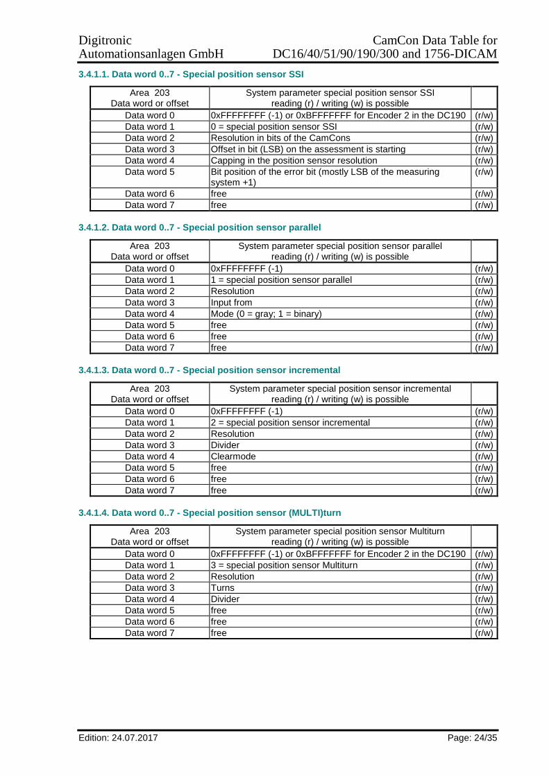
3.4.1.1. Data word 0..7 - Special position sensor SSI
Area 203 Data word or offset
System parameter special position sensor SSI reading (r) / writing (w) is possible
Data word 0 0xFFFFFFFF (-1) or 0xBFFFFFFF for Encoder 2 in the DC190 (r/w)
Data word 1 0 = special position sensor SSI (r/w)
Data word 2 Resolution in bits of the CamCons (r/w)
Data word 3 Offset in bit (LSB) on the assessment is starting (r/w)
Data word 4 Capping in the position sensor resolution (r/w)
Data word 5 Bit position of the error bit (mostly LSB of the measuring system +1)
(r/w)
Data word 6 free (r/w)
Data word 7 free (r/w)
3.4.1.2. Data word 0..7 - Special position sensor parallel
Area 203 Data word or offset
System parameter special position sensor parallel reading (r) / writing (w) is possible
Data word 0 0xFFFFFFFF (-1) (r/w)
Data word 1 1 = special position sensor parallel (r/w)
Data word 2 Resolution (r/w)
Data word 3 Input from (r/w)
Data word 4 Mode (0 = gray; 1 = binary) (r/w)
Data word 5 free (r/w)
Data word 6 free (r/w)
Data word 7 free (r/w)
3.4.1.3. Data word 0..7 - Special position sensor incremental
Area 203 Data word or offset
System parameter special position sensor incremental reading (r) / writing (w) is possible
Data word 0 0xFFFFFFFF (-1) (r/w)
Data word 1 2 = special position sensor incremental (r/w)
Data word 2 Resolution (r/w)
Data word 3 Divider (r/w)
Data word 4 Clearmode (r/w)
Data word 5 free (r/w)
Data word 6 free (r/w)
Data word 7 free (r/w)
3.4.1.4. Data word 0..7 - Special position sensor (MULTI)turn
Area 203 Data word or offset
System parameter special position sensor Multiturn reading (r) / writing (w) is possible
Data word 0 0xFFFFFFFF (-1) or 0xBFFFFFFF for Encoder 2 in the DC190 (r/w)
Data word 1 3 = special position sensor Multiturn (r/w)
Data word 2 Resolution (r/w)
Data word 3 Turns (r/w)
Data word 4 Divider (r/w)
Data word 5 free (r/w)
Data word 6 free (r/w)
Data word 7 free (r/w)

Digitronic CamCon Data Table for Automationsanlagen GmbH DC16/40/51/90/190/300 and 1756-DICAM
Edition: 24.07.2017 Page: 25/35
3.4.1.5. Data word 0..7 - Special position sensor (P)hase - (L)ock - (L)oop
Area 203 Data word or offset
System parameter special position sensor Phase - Lock - Loop reading (r) / writing (w) is possible
Data word 0 0xFFFFFFFF (-1) (r/w)
Data word 1 4 = special position sensor PLL (r/w)
Data word 2 Impulses for each input impulse (r/w)
Data word 3 Number of the impulses for each turn (r/w)
Data word 4 Error window (r/w)
Data word 5 Impulse input number (r/w)
Data word 6 Clear input number (r/w)
Data word 7 Synchronous output number (r/w)
3.4.1.6. Data word 0..7 - Special position sensor Timer in milliseconds
Area 203 Data word or offset
System parameter special position sensor Timer reading (r) / writing (w) is possible
Data word 0 0xFFFFFFFF (-1) (r/w)
Data word 1 5 = special position sensor Timer (r/w)
Data word 2 Resolution (total time) (r/w)
Data word 3 Time per step in ms (r/w)
Data word 4 Stop input (r/w)
Data word 5 Clear input (r/w)
Data word 6 free (r/w)
Data word 7 free (r/w)
3.4.1.7. Data word 0..7 - Special position sensor AG615 with exploit or turns
Area 203 Data word or offset
System parameter special position sensor AG615 reading (r) / writing (w) is possible
Data word 0 0xFFFFFFFF (-1) or 0xBFFFFFFF for Encoder 2 in the DC190 (r/w)
Data word 1 7 = special position sensor AG615 (r/w)
Data word 2 Resolution (r/w)
Data word 3 Exploit or Turns (r/w)
Data word 4 free (r/w)
Data word 5 free (r/w)
Data word 6 free (r/w)
Data word 7 free (r/w)
3.4.1.8. Data word 0..7 - special position sensor speed (SIM)ulation
Area 203 Data word or offset
System parameter special position sensor Speed Simulation reading (r) / writing (w) is possible
Data word 0 0xFFFFFFFF (-1) (r/w)
Data word 1 8 = special position sensor Simulation (r/w)
Data word 2 Resolution (r/w)
Data word 3 Impulses per second Example: Resolution 8192 impulses with 300 turns per minute. Impulses per second = 300 min-1 / 60 sec. * 8192 impulses
(r/w)
Data word 4 Stop input (r/w)
Data word 5 Clear input (r/w)
Data word 6 free (r/w)
Data word 7 free (r/w)

Digitronic CamCon Data Table for Automationsanlagen GmbH DC16/40/51/90/190/300 and 1756-DICAM
Edition: 24.07.2017 Page: 26/35
3.4.1.9. Data word 0..7 - Special position sensor (HIPER)face
Area 203 Data word or offset
System parameter special position sensor Hiperface reading (r) / writing (w) is possible
Data word 0 0xFFFFFFFF (-1) (r/w)
Data word 1 9 = Special position sensor Hiperface - Incremental with Roll-Over function.
(r/w)
Data word 2 Pre-multiplier (r/w)
Data word 3 Pre-divisor (r/w)
Data word 4 Resolution (r/w)
Data word 5 Clearmode (r/w)
Data word 6 free (r/w)
Data word 7 free (r/w)
3.4.1.10. Data word 0..7 - Special position sensor SSI2 for advanced settings
Area 203 Data word or offset
System parameter special position sensor SSI2 reading (r) / writing (w) is possible
Data word 0 0xFFFFFFFF (-1) or 0xBFFFFFFF for Encoder 2 in the DC190 (r/w)
Data word 1 10 = special position sensor SSI2 (r/w)
Data word 2 Resolution in bits of the CamCons (r/w)
Data word 3 Offset in bit (LSB) on the assessment is starting (r/w)
Data word 4 Bit position of the position sensor for a more accurate speed assessment (mostly LSB of the measuring system)
(r/w)
Data word 5 Bit position of the error bit (mostly LSB of the measuring system +1)
(r/w)
Data word 6 Bit position of the actual error: 3 bits (e.g. Out of Range Bit for Balluf BTL5 = Bit 3 solenoid error)
(r/w)
Data word 7 Mode (gray = 0 / binary= 1) (r/w)

Digitronic CamCon Data Table for Automationsanlagen GmbH DC16/40/51/90/190/300 and 1756-DICAM
Edition: 24.07.2017 Page: 27/35
3.5. Data area 204 - Parameterising analogous cam outputs
Area 204 Data word or offset
Parameterising analogous cam outputs reading (r) / writing (w) is possible
Data word 0 Minimum analogue value 1 (r/w)
Data word 1 Maximum analogue value 1 (r/w)
Data word 2 Interpolation analogous 1 (0=off / 1=on) (r/w)
Data word 3 Disable input analogous cams 1 (0..200) (r/w)
Data word 4 Disable value analogous cams 1 (r/w)
Data word 5 Strengthening (Gain) analogous1 (r/w)
Data word 6 Offset (16Bit)+- analogous 1 (r/w)
Data word 7..90 " " 2..13 (r/w)
Data word 91 Minimum analogous 14 (r/w)
Data word 92 Maximum analogous 14 (r/w)
Data word 93 Interpolation analogous 14 (0=off / 1=on) (r/w)
Data word 94 Disable input analogous cams 14 (0..200) (r/w)
Data word 95 Disable value analogous cams 14 (r/w)
Data word 96 Strengthening (Gain) analogous14 (r/w)
Data word 97 Offset (16Bit)+- analogous 14 (r/w)
3.6. Data area 205 - Device configuration, Complete deletion, Error acknowledgement, EE-Lock, CP16
Area 205 Data word or offset
Device configuration reading (r) / writing (w) is possible
Data word 0 Device number of the CamCon for the serial interface (0..63) (r/w)
Data word 1 Complete deletion If an 0xFFFFFFFF (-1) is written here, the whole memory of the CamCon will be deleted.
(w)
Data word 2 Hardware reset If an 0xFFFFFFFF (-1) is written here, the CamCon will be restarted. Note: This command will not be acknowledged.
(w)
Data word 3 Acknowledge actual or off error If an 0xFFFFFFFF (-1) is written, an acknowledgement of an error message present on the CamCon is being tried.
(w)
Data word 4 EEProm Lock (0 = unlock / 1 = lock) It the EEProm is locked = 1 all subsequently programmed data will only be written into the RAM. If the voltage will be switched off, then they would be deleted. Attention: After a complete deletion, this value will also be deleted.
(r/w)
Data word 5 Number of hardware inputs (0..200) without CP16 (r/w)
Data word 6 Number of hardware outputs (8..200) without CP16 (r/w)
Data word 7 CP type or bus type 0 = no CP 1 = CP16/P/IO
(r/w)
Data word 8 Profibus DP address if CP type = 1 Note: The new DP address will only be used after Power UP.
(r/w)
Data word 9 Number of the inputs simulated by the CP16 if CP type = 1 (r/w)
Data word 10 Number of the outputs simulated by the CP16 if CP type = 1 (r/w)
Data word 11 Communication mode 0 = CamBUS 1 = Standard 9600 bauds 2 = Multiuser 3 = S5-L1 4 = 3964(R) (4Byte) 5 = 3964(r) (2Byte) 38400 bauds
(r/w)
Data word 12 CamCon option (0=none/1=SPS/2=PLC+Text No/...) (r)

Digitronic CamCon Data Table for Automationsanlagen GmbH DC16/40/51/90/190/300 and 1756-DICAM
Edition: 24.07.2017 Page: 28/35
3.7. Data area 206..209 - Target values in the PLC logic module If a timer counter or a shift register function has been used in a network of the PLC logic module, the corresponding target values can be modified by the data areas 206 through 209. To do so, it is necessary to know the position of the network in the PLC logic module. If the timer is located e.g. In the area O005 = hardware output number 5, the data word 4 needs to be used in the data area 206 for writing or reading the target value.
3.7.1. Data area 206 - Target values in the area O of the PLC logic module
Area 206 Data word or offset
Target values in the area O of the PLC logic module reading (r) / writing (w) is possible
Data word 0 Target value output O001 For timer: Specification time in 0.1ms For counter: Specification count value For shift register Length of the shift register in steps Note: When writing from the timer and counter, the values will be reset in the corresponding timer or counter! In case of changes of the length of the shift register, signals may occur several times or not at all!
(r/w)
Data word 1 Taget value output O002 (r/w)
" " " (r/w)
Data word 198 Taget value output O199 (r/w)
Data word 199 Taget value output O200 (r/w)
3.7.2. Data area 207 - Target values in the area P of the PLC logic module
Area 207 Data word or offset
Target values in the area P of the PLC logic module reading (r) / writing (w) is possible
Data word 0 Taget value output P001 (r/w)
Data word 1 Target value output P002 (r/w)
" " " (r/w)
Data word 990 Target value output P991 (r/w)
Data word 991 Target value output P992 (r/w)
3.7.3. Data area 208 - Target values in the area M of the PLC logic module
Area 208 Data word or offset
Target values in the area M of the PLC logic module reading (r) / writing (w) is possible
Data word 0 Target value output M001 (r/w)
Data word 1 Taget value output M002 (r/w)
" " " (r/w)
Data word 990 Target value output M991 (r/w)
Data word 991 Target value output M992 (r/w)
3.7.4. Data area 209 - Target values in the area X of the PLC logic module
Area 209 Data word or offset
Target values in the area X of the PLC logic module reading (r) / writing (w) is possible
Data word 0 Target value output X001 (r/w)
Data word 1 Target value output X002 (r/w)
" " " (r/w)
Data word 990 Target value output X991 (r/w)
Data word 991 Target value output X992 (r/w)

Digitronic CamCon Data Table for Automationsanlagen GmbH DC16/40/51/90/190/300 and 1756-DICAM
Edition: 24.07.2017 Page: 29/35
3.8. Data area 210..213 - Actual values in the PLC logic module If a timer counter or a shift register function is used in a network of the PLC logic module, the current actual value can be read or also modified by the data areas 210 through 213. To do so, it is necessary to know the position of the network in the PLC logic module. If the counter is located e.g. In the area M001 = flag number 1, the data word 0 needs to be used in the data area 212 for writing or reading the actual value. 3.8.1. Data area 210 - Actual values in the area O of the PLC logic module
Area 210 Data word or offset
Actual values in the area O of the PLC logic module reading (r) / writing (w) is possible
Data word 0 Actual value output O001 For timer: Current time of the timer in 0.1ms For counter: Current count value For shift register It is only possible to write a 0,
in doing so, all bits in the shift register will be deleted.
Note: When writing actual values for timer and counter, the corresponding target value must not be exceeded or undercut.
(r/w)
Data word 1 Actual value output O002 (r/w)
" " " (r/w)
Data word 198 Actual value output O199 (r/w)
Data word 199 Actual value output O200 (r/w)
3.8.2. Data area 211 - Actual values in the area P of the PLC logic module
Area 211 Data word or offset
Actual values in the area P of the PLC logic module reading (r) / writing (w) is possible
Data word 0 Actual value output P001 (r/w)
Data word 1 Actual value output P002 (r/w)
" " " (r/w)
Data word 990 Actual value output P991 (r/w)
Data word 991 Actual value output P992 (r/w)
3.8.3. Data area 212 - Actual values in the area M of the PLC logic module
Area 212 Data word or offset
Actual values in the area M of the PLC logic module reading (r) / writing (w) is possible
Data word 0 Actual value output M001 (r/w)
Data word 1 Actual value output M002 (r/w)
" " " (r/w)
Data word 990 Actual value output M991 (r/w)
Data word 991 Actual value output M992 (r/w)
3.8.4. Data area 213 - Actual values in the area X of the PLC logic module
Area 213 Data word or offset
Actual values in the area X of the PLC logic module reading (r) / writing (w) is possible
Data word 0 Actual value output X001 (r/w)
Data word 1 Actual value output X002 (r/w)
" " " (r/w)
Data word 990 Actual value output X991 (r/w)
Data word 991 Actual value output X992 (r/w)
Digitronic CamCon Data Table for Automationsanlagen GmbH DC16/40/51/90/190/300 and 1756-DICAM
Edition: 24.07.2017 Page: 30/35
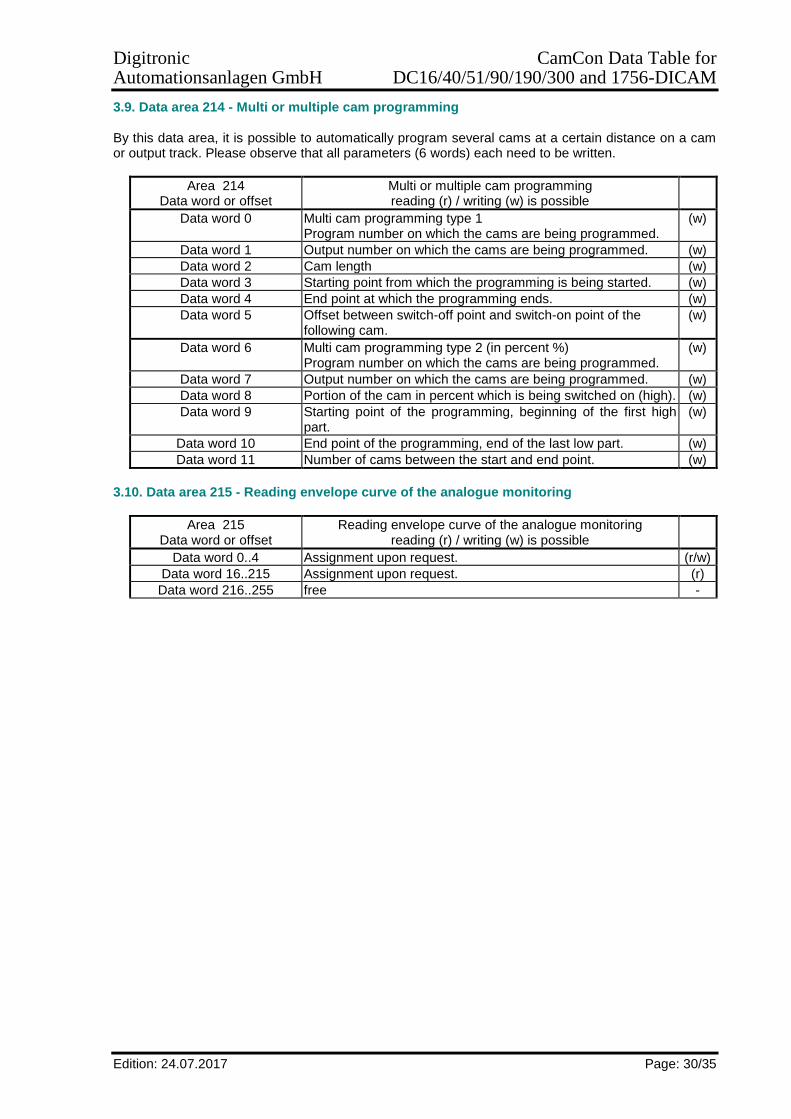
3.9. Data area 214 - Multi or multiple cam programming By this data area, it is possible to automatically program several cams at a certain distance on a cam or output track. Please observe that all parameters (6 words) each need to be written.
Area 214 Data word or offset
Multi or multiple cam programming reading (r) / writing (w) is possible
Data word 0 Multi cam programming type 1 Program number on which the cams are being programmed.
(w)
Data word 1 Output number on which the cams are being programmed. (w)
Data word 2 Cam length (w)
Data word 3 Starting point from which the programming is being started. (w)
Data word 4 End point at which the programming ends. (w)
Data word 5 Offset between switch-off point and switch-on point of the following cam.
(w)
Data word 6 Multi cam programming type 2 (in percent %) Program number on which the cams are being programmed.
(w)
Data word 7 Output number on which the cams are being programmed. (w)
Data word 8 Portion of the cam in percent which is being switched on (high). (w)
Data word 9 Starting point of the programming, beginning of the first high part.
(w)
Data word 10 End point of the programming, end of the last low part. (w)
Data word 11 Number of cams between the start and end point. (w)
3.10. Data area 215 - Reading envelope curve of the analogue monitoring
Area 215 Data word or offset
Reading envelope curve of the analogue monitoring reading (r) / writing (w) is possible
Data word 0..4 Assignment upon request. (r/w)
Data word 16..215 Assignment upon request. (r)
Data word 216..255 free -
Digitronic CamCon Data Table for Automationsanlagen GmbH DC16/40/51/90/190/300 and 1756-DICAM
Edition: 24.07.2017 Page: 31/35
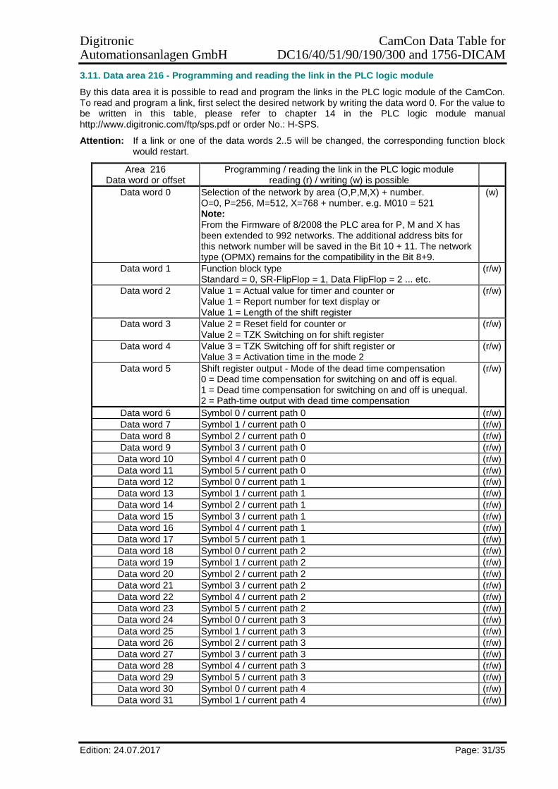
3.11. Data area 216 - Programming and reading the link in the PLC logic module
By this data area it is possible to read and program the links in the PLC logic module of the CamCon. To read and program a link, first select the desired network by writing the data word 0. For the value to be written in this table, please refer to chapter 14 in the PLC logic module manual http://www.digitronic.com/ftp/sps.pdf or order No.: H-SPS.
Attention: If a link or one of the data words 2..5 will be changed, the corresponding function block would restart.
Area 216 Data word or offset
Programming / reading the link in the PLC logic module reading (r) / writing (w) is possible
Data word 0 Selection of the network by area (O,P,M,X) + number. O=0, P=256, M=512, X=768 + number. e.g. M010 = 521 Note: From the Firmware of 8/2008 the PLC area for P, M and X has been extended to 992 networks. The additional address bits for this network number will be saved in the Bit 10 + 11. The network type (OPMX) remains for the compatibility in the Bit 8+9.
(w)
Data word 1 Function block type Standard = 0, SR-FlipFlop = 1, Data FlipFlop = 2 ... etc.
(r/w)
Data word 2 Value 1 = Actual value for timer and counter or Value 1 = Report number for text display or Value 1 = Length of the shift register
(r/w)
Data word 3 Value 2 = Reset field for counter or Value 2 = TZK Switching on for shift register
(r/w)
Data word 4 Value 3 = TZK Switching off for shift register or Value 3 = Activation time in the mode 2
(r/w)
Data word 5 Shift register output - Mode of the dead time compensation 0 = Dead time compensation for switching on and off is equal. 1 = Dead time compensation for switching on and off is unequal. 2 = Path-time output with dead time compensation
(r/w)
Data word 6 Symbol 0 / current path 0 (r/w)
Data word 7 Symbol 1 / current path 0 (r/w)
Data word 8 Symbol 2 / current path 0 (r/w)
Data word 9 Symbol 3 / current path 0 (r/w)
Data word 10 Symbol 4 / current path 0 (r/w)
Data word 11 Symbol 5 / current path 0 (r/w)
Data word 12 Symbol 0 / current path 1 (r/w)
Data word 13 Symbol 1 / current path 1 (r/w)
Data word 14 Symbol 2 / current path 1 (r/w)
Data word 15 Symbol 3 / current path 1 (r/w)
Data word 16 Symbol 4 / current path 1 (r/w)
Data word 17 Symbol 5 / current path 1 (r/w)
Data word 18 Symbol 0 / current path 2 (r/w)
Data word 19 Symbol 1 / current path 2 (r/w)
Data word 20 Symbol 2 / current path 2 (r/w)
Data word 21 Symbol 3 / current path 2 (r/w)
Data word 22 Symbol 4 / current path 2 (r/w)
Data word 23 Symbol 5 / current path 2 (r/w)
Data word 24 Symbol 0 / current path 3 (r/w)
Data word 25 Symbol 1 / current path 3 (r/w)
Data word 26 Symbol 2 / current path 3 (r/w)
Data word 27 Symbol 3 / current path 3 (r/w)
Data word 28 Symbol 4 / current path 3 (r/w)
Data word 29 Symbol 5 / current path 3 (r/w)
Data word 30 Symbol 0 / current path 4 (r/w)
Data word 31 Symbol 1 / current path 4 (r/w)

Digitronic CamCon Data Table for Automationsanlagen GmbH DC16/40/51/90/190/300 and 1756-DICAM
Edition: 24.07.2017 Page: 32/35
Area 216 Data word or offset
Programming / reading the link in the PLC logic module reading (r) / writing (w) is possible
Data word 32 Symbol 2 / current path 4 (r/w)
Data word 33 Symbol 3 / current path 4 (r/w)
Data word 34 Symbol 4 / current path 4 (r/w)
Data word 35 Symbol 5 / current path 4 (r/w)
3.12. Data area 217 - Programming the IO Router
By this special data area, it would be possible to set the hardware of the CamCon to special configurations.
Area 217 Data word or offset
Setting / reading the IO hardware router reading (r) / writing (w) is possible
Data word 0 Positon of the module in the chain of the external interface (r/w)
Data word 1 Status Bit:0 = 0 module deleted (r) / delete (w) Bit:0 = 1 module existing (r) / creating (w) Bit:1 = 1 executing CamCon restart (w)
(r/w)
Data word 2 Hardware-ID of the assembly e.g. DC16 IO = 0x650 hex (r/w)
Data word 3 I/O Byte assignment of the assembly to the CamCon E/As (r/w)
Data word 4 I/O Byte assignment of the assembly to the CamCon E/As (r/w)
Data word 5 I/O Byte assignment of the assembly to the CamCon E/As (r/w)
Data word 6 I/O Byte assignment of the assembly to the CamCon E/As (r/w)
Data word 7 I/O Byte assignment of the assembly to the CamCon E/As (r/w)
Data word 8 I/O Byte assignment of the assembly to the CamCon E/As (r/w)
Data word 9 I/O Byte assignment of the assembly to the CamCon E/As (r/w)
Data word 10 I/O Byte assignment of the assembly to the CamCon E/As (r/w)
Data word 11 I/O Byte assignment of the assembly to the CamCon E/As (r/w)
Data word 12 I/O Byte assignment of the assembly to the CamCon E/As (r/w)
Data word 13 I/O Byte assignment of the assembly to the CamCon E/As (r/w)
Data word 14 I/O Byte assignment of the assembly to the CamCon E/As (r/w)
Data word 15 I/O Byte assignment of the assembly to the CamCon E/As (r/w)
Data word 16 I/O Byte assignment of the assembly to the CamCon E/As (r/w)
Data word 17..19 free -
Data word 20..36 DC300 + 1756-DICAM Backplan Router or CamCon CP16/P/IO I/O assignment. Occupation upon request
(r/w)
Digitronic CamCon Data Table for Automationsanlagen GmbH DC16/40/51/90/190/300 and 1756-DICAM
Edition: 24.07.2017 Page: 33/35
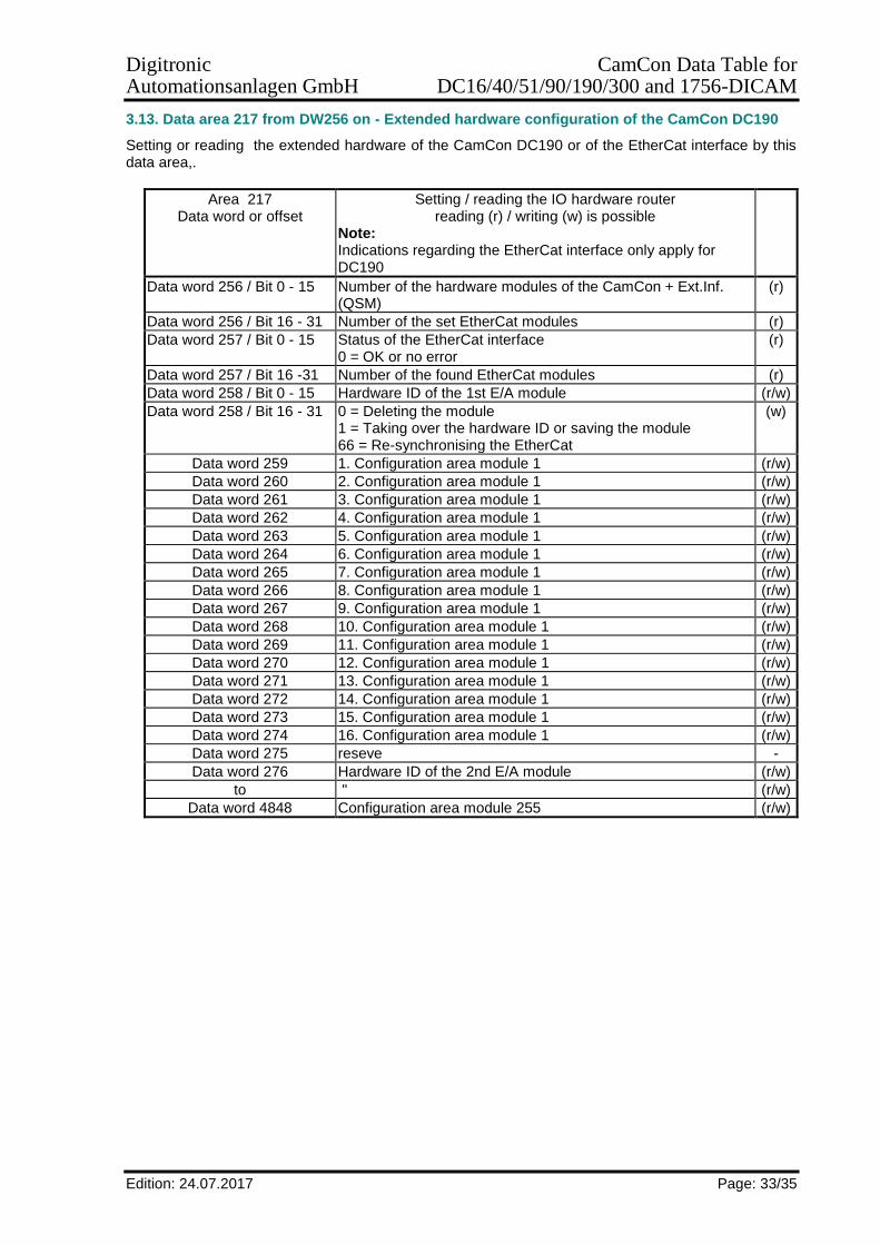
3.13. Data area 217 from DW256 on - Extended hardware configuration of the CamCon DC190
Setting or reading the extended hardware of the CamCon DC190 or of the EtherCat interface by this data area,.
Area 217 Data word or offset
Setting / reading the IO hardware router reading (r) / writing (w) is possible
Note: Indications regarding the EtherCat interface only apply for DC190
Data word 256 / Bit 0 - 15 Number of the hardware modules of the CamCon + Ext.Inf. (QSM)
(r)
Data word 256 / Bit 16 - 31 Number of the set EtherCat modules (r)
Data word 257 / Bit 0 - 15 Status of the EtherCat interface 0 = OK or no error
(r)
Data word 257 / Bit 16 -31 Number of the found EtherCat modules (r)
Data word 258 / Bit 0 - 15 Hardware ID of the 1st E/A module (r/w)
Data word 258 / Bit 16 - 31 0 = Deleting the module 1 = Taking over the hardware ID or saving the module 66 = Re-synchronising the EtherCat
(w)
Data word 259 1. Configuration area module 1 (r/w)
Data word 260 2. Configuration area module 1 (r/w)
Data word 261 3. Configuration area module 1 (r/w)
Data word 262 4. Configuration area module 1 (r/w)
Data word 263 5. Configuration area module 1 (r/w)
Data word 264 6. Configuration area module 1 (r/w)
Data word 265 7. Configuration area module 1 (r/w)
Data word 266 8. Configuration area module 1 (r/w)
Data word 267 9. Configuration area module 1 (r/w)
Data word 268 10. Configuration area module 1 (r/w)
Data word 269 11. Configuration area module 1 (r/w)
Data word 270 12. Configuration area module 1 (r/w)
Data word 271 13. Configuration area module 1 (r/w)
Data word 272 14. Configuration area module 1 (r/w)
Data word 273 15. Configuration area module 1 (r/w)
Data word 274 16. Configuration area module 1 (r/w)
Data word 275 reseve -
Data word 276 Hardware ID of the 2nd E/A module (r/w)
to " (r/w)
Data word 4848 Configuration area module 255 (r/w)
Digitronic CamCon Data Table for Automationsanlagen GmbH DC16/40/51/90/190/300 and 1756-DICAM
Edition: 24.07.2017 Page: 34/35
3.14. Data area 218 - Direct EE-Prom data memory access
Because of this data area, it would be possible to read and write the EE Prom or the cam and program memory of the CamCon. It is only intended for internal use by Digitronic.
! Attention: If this data area has been described, data losses would be possible.
3.15. Data area 219 - Adjusting NLT table
By this data area it is possible to read and write the NLT table (non-linear dead time).
3.16. Data area 221 - WZS - Setting digital monitoring
By this data area it is possible to set the digital WZS (tool protection).
3.17. Data area 222 - WZS - Setting analogous monitoring
By this data area it is possible to set the analogous WZS tool protection).
3.18. Data area 223 - Trend function
By this data area it is possible to set the trend function (logics - analyser) of the CamCon and read the recorded signals.

Digitronic CamCon Data Table for Automationsanlagen GmbH DC16/40/51/90/190/300 and 1756-DICAM
Edition: 24.07.2017 Page: 35/35
3.19. Data area 241..254 - Programming / reading analogous cams 1..14
In the data area 241 to 254 the analogous cams 1 through 14 are programmed and read in the current program. At this, the area number minus 240 corresponds to the analogous output number.
Area 241..254 Data word or offset
Programming / reading analogous cams 1..14 reading (r) / writing (w) is possible
Data word 0 free -
Data word 1 Base 1 (r/w)
Data word 2 Analogue value 1 (r/w)
Data word 3 Base 2 (r/w)
Data word 4 Analogue value 2 (r/w)
Data word 5 Base 3 (r/w)
Data word 6 Analogue value 3 (r/w)
Data word 7..250 " 4..125 (r/w)
Data word 251 free -
Data word 252 free -
Data word 253 free -
Data word 254 Number of currently occupied bases (r)
Data word 255 free -
Note:
- The base and the analogue value always need to be mutually transmitted (min. 8 bytes) Attention: For DigiWEB it is possible to transfer several cams in blocks depending on the transport
protocol. In this way, bases might get lost. Mind the 128-byte limit and only transfer max. 16 cams for each command.
- Describe an empty cam in order to create a new, analogue cam.
- An empty, analogous cam will deliver a base of 0x80000000 Hex.
- If a cam would be changed, the new base and analogue value needs to be transferred to the position of the old cam (cam number).
- An analogous cam will be deleted if the base and the analogous value will be set to 0x80000000 Hex.
- If you would like to reprogram the whole, analogous cam track and delete all existing cams, you will transfer at least 2 cams in a row (16 bytes) starting with the first cam.