caltrans seismic design criteria seismic design
TRANSCRIPT

CALTRANSCALTRANSCALTRANSCALTRANSCALTRANS
SEISMIC DESIGN CRITERIASEISMIC DESIGN CRITERIASEISMIC DESIGN CRITERIASEISMIC DESIGN CRITERIASEISMIC DESIGN CRITERIA VERSION 13VERSION 13VERSION 13VERSION 13VERSION 13
FEBRUARY 2004FEBRUARY 2004FEBRUARY 2004FEBRUARY 2004FEBRUARY 2004
11
SEISMIC DESIGN CRITERIA bull FEBRUARY 2004 bull VERSION 13
1 INTRODUCTION
The Caltrans Seismic Design Criteria (SDC) specify the minimum seismic design requirements that are necessary to meet the performance goals established for Ordinary bridges in Memo to Designers (MTD) 20-1
The SDC is a compilation of new seismic design criteria and existing seismic design criteria previously documented in various locations The goal is to update all the Offices of Structures Design (OSD) design manuals1 on a periodic basis to reflect the current state of practice for seismic bridge design As information is incorporated into the design manuals the SDC will serve as a forum to document Caltransrsquo latest changes to the seismic design methodology Proposed revisions to the SDC will be reviewed by OSD management according to the process outlined in MTD 20-11
The SDC applies to Ordinary Standard bridges as defined in Section 11 Ordinary Nonstandard bridges require project specific criteria to address their non-standard features Designers should refer to the OSD design manuals for seismic design criteria not explicitly addressed by the SDC
The following criteria identify the minimum requirements for seismic design Each bridge presents a unique set of design challenges The designer must determine the appropriate methods and level of refinement necessary to design and analyze each bridge on a case-by-case basis The designer must exercise judgment in the application of these criteria Situations may arise that warrant detailed attention beyond what is provided in the SDC The designer should refer to other resources to establish the correct course of action The OSD Senior Seismic Specialists the OSD Earthquake Committee and the Earthquake Engineering Office of Structure Design Services and Earthquake Engineering (SDSEE) should be consulted for recommendations
Deviations to these criteria shall be reviewed and approved by the Section Design Senior or the Senior Seismic Specialist and documented in the project file Significant departures shall be presented to the Type Selection Panel andor the Design Branch Chief for approval as outlined in MTD 20-11
This document is intended for use on bridges designed by and for the California Department of Transportation It reflects the current state of practice at Caltrans This document contains references specific and unique to Caltrans and may not be applicable to other parties either institutional or private
Definition of an Ordinary Standard Bridge
A structure must meet all of the following requirements to be classified as an Ordinary Standard bridge
bull Span lengths less than 300 feet (90 m)
bull Constructed with normal weight concrete girder and column or pier elements
bull Horizontal members either rigidly connected pin connected or supported on conventional bearings by the substructure isolation bearings and dampers are considered nonstandard components
1 Caltrans Design ManualsBridge Design Specifications Memo To Designers Bridge Design Details Bridge Design Aids Bridge Design Practice
SEISMIC DESIGN CRITERIA 1-1
12
13
SECTION 1 - INTRODUCTION
bull Dropped bent caps or integral bent caps terminating inside the exterior girder C-bents outrigger bents and offset columns are nonstandard components
bull Foundations supported on spread footing pile cap wpiles or pile shafts
bull Soil that is not susceptible to liquefaction lateral spreading or scour
Types of Components Addressed in the SDC
The SDC is focused on concrete bridges Seismic criteria for structural steel bridges are being developed independently and will be incorporated into the future releases of the SDC In the interim inquiries regarding the seismic performance of structural steel components shall be directed to the Structural Steel Technical Specialist and the Structural Steel Committee
The SDC includes seismic design criteria for Ordinary Standard bridges constructed with the types of components listed in Table 1
Table 1
Superstructure Substructure Foundation Abutment Cast-in-place Reinforced concrete Footings or pile caps End diaphragms
nforced concretei-- Re umn bentsle colngi-- S Shafts Short seat oned concretei-- Post-tens umn bentsl-coitl-- Mu nedi-- M High cantilever
Precast sller wai-- P -- CIDH
nforced concretei-- Re onsie extensli-- P Piles
oned concretei-- Pre-tens -- CISS
oned concretei-- Post-tens -- Precast PS concrete
peipl-- Stee
onsi-- H Sect -- CIDH
etaryi-- Propr
Bridge Systems
A bridge system consists of superstructure and substructure components The bridge system can be further characterized as an assembly of subsystems Examples of bridge subsystems include
bull Longitudinal frames separated by expansion joints
bull Multi-column or single column transverse bents supported on footings piles or shafts
bull Abutments
SEISMIC DESIGN CRITERIA 1-2
14
SEISMIC DESIGN CRITERIA bull FEBRUARY 2004 bull VERSION 13
Traditionally the entire bridge system has been referred to as the global system whereas an individual bent or column has been referred to as a local system It is preferable to define these terms as relative and not absolute measures For example the analysis of a bridge frame is global relative to the analysis of a column subsystem but is local relative to the analysis of the entire bridge system
Local and Global Behavior
The term ldquolocalrdquo when pertaining to the behavior of an individual component or subsystem constitutes its response independent of the effects of adjacent components subsystems or boundary conditions The term ldquoglobalrdquo describes the overall behavior of the component subsystem or bridge system including the effects of adjacent components subsystems or boundary conditions See Section 222 for the distinction between local and global displacements
SEISMIC DESIGN CRITERIA 1-3
21
SEISMIC DESIGN CRITERIA bull FEBRUARY 2004 bull VERSION 13
2 DEMANDS ON STRUCTURE COMPONENTS
Ground Motion Representation
Caltrans Materials Engineering and Testing Service (METS) and Geotechnical Services (GS) will provide the following data defining the ground motion in the Preliminary Geology Recommendations (PGR)
bull Soil Profile Type bull Peak rock acceleration for the Maximum Credible Earthquake (MCE) bull Moment magnitude for the MCE bull Acceleration Response Spectrum (ARS) curve recommendation bull Fault distance
Refer to Memo to Designers 1-35 for the procedure to request foundation data
211 Spectral Acceleration
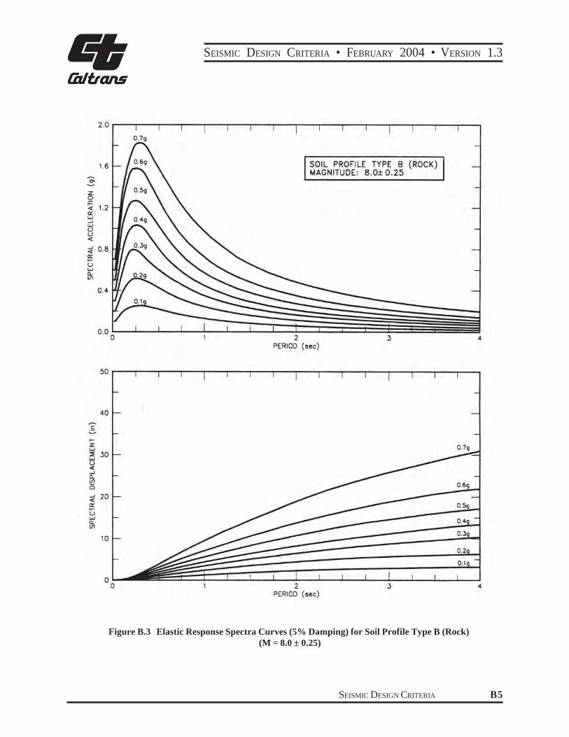
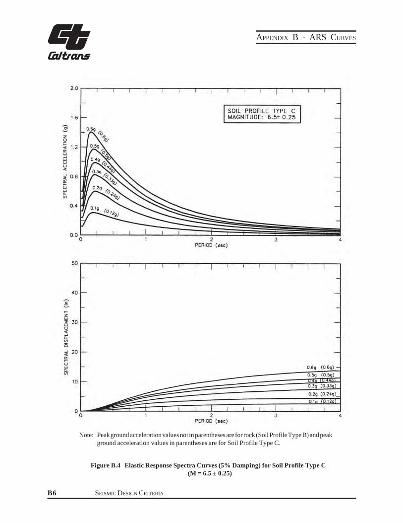
The horizontal mean spectral acceleration can be selected from an ARS curve GEE will recommend a standard ARS curve a modified standard ARS curve or a site-specific ARS curve Standard ARS curves for California are included in Appendix B See Section 612 for information regarding modified ARS curves and site specific ARS curves
212 Horizontal Ground Motion
Earthquake effects shall be determined from horizontal ground motion applied by either of the following methods
Method 1 The application of the ground motion in two orthogonal directions along a set of global axes where the longitudinal axis is typically represented by a chord connecting the two abutments see Figure 21
Case I Combine the response resulting from 100 of the transverse loading with the corresponding response from 30 of the longitudinal loading
Case II Combine the response resulting from 100 of the longitudinal loading with the corresponding response from 30 of the transverse loading
Method 2 The application of the ground motion along the principal axes of individual components The ground motion must be applied at a sufficient number of angles to capture the maximum deformation of all critical components
SEISMIC DESIGN CRITERIA 2-1
SECTION 2 - DEMANDS ON STRUCTURE COMPONENTS
Figure 21 LocalndashGlobal Axis Definition
213 Vertical Ground Motion
For Ordinary Standard bridges where the site peak rock acceleration is 06g or greater an equivalent static vertical load shall be applied to the superstructure to estimate the effects of vertical acceleration2 The superstructure shall be designed to resist the applied vertical force as specified in Section 722 A case-by-case determination on the effect of vertical load is required for Non-standard and Important bridges
214 VerticalHorizontal Load Combination
A combined verticalhorizontal load analysis is not required for Ordinary Standard bridges
215 Damping
A 5 damped elastic ARS curve shall be used for determining the accelerations for Ordinary Standard concrete bridges Damping ratios on the order of 10 can be justified for bridges that are heavily influenced by energy dissipation at the abutments and are expected to respond like single-degree-of-freedom systems A reduction factor RD can be applied to the 5 damped ARS coefficient used to calculate the displacement demand
This is an interim method of approximating the effects of vertical acceleration on superstructure capacity The intent is to ensure all superstructure types especially lightly reinforced sections such as PS box girders have a nominal amount of mild reinforcement available to resist the combined effects of dead load earthquake and prestressing in the upward or downward direction This is a subject of continued study
SEISMIC DESIGN CRITERIA 2-2
2
22
SEISMIC DESIGN CRITERIA bull FEBRUARY 2004 bull VERSION 13
The following characteristics are typically good indicators that higher damping may be anticipated [3]
bull Total length less than 300 feet (90 m)
bull Three spans or less
bull Abutments designed for sustained soil mobilization
bull Normal or slight skew (less than 20 degrees)
bull Continuous superstructure without hinges or expansion joints
15RD = + 05 (21)[40c +1]
ARSrsquo=( RD)(ARS)
c = damping ratio (005 lt c lt 01)
ARS = 5 damped ARS curve
ARSrsquo = modified ARS curve
However abutments that are designed to fuse (seat type abutment with backwalls) or respond in a flexible manner may not develop enough sustained soil-structure interaction to rely on the higher damping ratio
Displacement Demand
221 Estimated Displacement
The global displacement demand estimate ∆D for Ordinary Standard bridges can be determined by linear elastic analysis utilizing effective section properties as defined in Section 56
Equivalent Static Analysis (ESA) as defined in Section 521 can be used to determine ∆D if a dynamic analysis will not add significantly more insight into behavior ESA is best suited for bridges or individual frames with the following characteristics
bull Response primarily captured by the fundamental mode of vibration with uniform translation
bull Simply defined lateral force distribution (eg balanced spans approximately equal bent stiffness)
bull Low skew
Elastic Dynamic Analysis (EDA) as defined in Section 522 shall be used to determine ∆D for all other Ordinary Standard bridges
The global displacement demand estimate shall include the effects of soilfoundation flexibility if they are significant
SEISMIC DESIGN CRITERIA 2-3
SECTION 2 - DEMANDS ON STRUCTURE COMPONENTS
222 Global Structure Displacement and Local Member Displacement
Global structure displacement ∆D is the total displacement at a particular location within the structure or subsystem The global displacement will include components attributed to foundation flexibility ∆ f (ie foundation rotation or translation) flexibility of capacity protected components such as bent caps ∆b and the flexibility attributed to elastic and inelastic response of ductile members ∆y and ∆p respectively The analytical model for determining the displacement demands shall include as many of the structural characteristics and boundary conditions affecting the structurersquos global displacements as possible The effects of these characteristics on the global displacement of the structural system are illustrated in Figures 22 amp 23
Local member displacements such as column displacements ∆col are defined as the portion of global displacement attributed to the elastic displacement ∆y and plastic displacement ∆p of an individual member from the point of maximum moment to the point of contra-flexure as shown in Figure 22
223 Displacement Ductility Demand
Displacement ductility demand is a measure of the imposed post-elastic deformation on a member Displacement ductility is mathematically defined by equation 22
∆Dmicro = D ∆Y (i) (22)
Where ∆D = The estimated global frame displacement demand defined in Section 222
∆Y(i) = The yield displacement of the subsystem from its initial position to the formation of plastic hinge (i) See Figure 23
224 Target Displacement Ductility Demand
The target displacement ductility demand values for various components are identified below These target values have been calibrated to laboratory test results of fix-based cantilever columns where the global displacement equals the columnrsquos displacement The designer should recognize as the framing system becomes more complex and boundary conditions are included in the demand model a greater percentage of the global displacement will be attributed to the flexibility of components other than the ductile members within the frame These effects are further magnified when elastic displacements are used in the ductility definition specified in equation 22 and shown in Figure 23 For such systems including but not limited to Type I or Type II shafts the global ductility demand values listed below may not be achieved The target values may range between 15 and 35 where specific values cannot be defined
Single Column Bents supported on fixed foundation microD le 4
Multi-Column Bents supported on fixed or pinned footings microD le 5
Pier Walls (weak direction) supported on fixed or pinned footings microD le 5
Pier Walls (strong direction) supported on fixed or pinned footings microD le 1
SEISMIC DESIGN CRITERIA 2-4
SEISMIC DESIGN CRITERIA bull FEBRUARY 2004 bull VERSION 13
Minimum ductility values are not prescribed The intent is to utilize the advantages of flexible systems specifically to reduce the required strength of ductile members and minimize the demand imparted to adjacent capacity protected components Columns or piers with flexible foundations will naturally have low displacement ductility demands because of the foundationrsquos contribution to ∆Y The minimum lateral strength requirement in Section 35 or the P-∆ requirements in Section 42 may govern the design of frames where foundation flexibility lengthens the period of the structure into the range where the ARS demand is typically reduced
∆D ∆D∆D
∆Y ∆Y ∆Y
∆ col ∆col ∆col
∆ col
∆Ycol
∆p ∆f ∆Ycol
∆p ∆f ∆pY
CASE A CASE B
Fixed Footing Foundation Flexibility
Note For a cantilever column wfixed base ∆colY = ∆Y
ARS
Demand
Capacity
A
B
Foundation Flexibility
Effect
BA A B ∆∆ ∆ ∆Y Y D D
Displacement
Figure 22 The Effects of Foundation Flexibility on Force-Deflection Curve of a Single Column Bent
SEISMIC DESIGN CRITERIA 2-5
SECTION 2 - DEMANDS ON STRUCTURE COMPONENTS
∆ col ∆b
∆D
f∆col ∆b
∆D
∆col
3 1
∆D
4 2
3 1
4 2
3 1
4 2
∆
Rigid Bent Cap CASE A
Flexible Bent Cap amp Flexible Foundation CASE C
Flexible Bent Cap
CASE B
Assumed Plastic Hinge Sequence
Lateral Force
ARS Demand
∆ ∆
Capacity
A B
A
B
C
C
∆ ∆Y4Y1 Y2 Y3 ∆
D Displacement
Figure 23 The Effects of Bent Cap and Foundation Flexibility on Force-Deflection Curve of a Bent Frame
SEISMIC DESIGN CRITERIA 2-6
SEISMIC DESIGN CRITERIA bull FEBRUARY 2004 bull VERSION 13
A A A A
B B C C
D D
Constant concrete cover
Increased concrete cover below ground
Concentric column and shaft cages Enlarged
Shaft
ReinforcingCage
Section A-A Section B-B Section C-C Section D-D
TYPE I SHAFTS TYPE II SHAFTS
Type I Pile Shafts
Type I pile shafts are designed so the plastic hinge will form below ground in the pile shaft The concrete cover and area of transverse and longitudinal reinforcement may change between the column and Type I pile shaft but the cross section of the confined core is the same for both the column and the pile shaft The global displacement ductility demand microD for a Type I pile shaft shall be less than or equal to the microD for the column supported by the shaft
Type II Pile Shafts
Type II pile shafts are designed so the plastic hinge will form at or above the shaftcolumn interface thereby containing the majority of inelastic action to the ductile column element Type II shafts are usually enlarged pile shafts characterized by a reinforcing cage in the shaft that has a diameter larger than the column it supports Type II pile shafts shall be designed to remain elastic microD le 1 See Section 7732 for design requirements for Type II pile shafts
Figure 24 Pile Shaft Definitions
NOTE Generally the use of Type II Pile Shafts should be discussed and approved at the Type Selection Meeting Type II Pile Shafts will increase the foundation costs compared to Type I Pile Shafts however there is an advantage of improved post-earthquake inspection and repair Typically Type I shaft is appropriate for short columns while Type II shaft is used in conjunction with taller columns The end result shall be a structure with an appropriate fundamental period as discussed elsewhere
SEISMIC DESIGN CRITERIA 2-7
SECTION 2 - DEMANDS ON STRUCTURE COMPONENTS
23 Force Demand
The structure shall be designed to resist the internal forces generated when the structure reaches its Collapse Limit State The Collapse Limit State is defined as the condition when a sufficient number of plastic hinges have formed within the structure to create a local or global collapse mechanism
231 Moment Demand
The column design moments shall be determined by the idealized plastic capacity of the columnrsquos cross section col col colM defined in Section 33 The overstrength moment M defined in Section 431 the associated shear V defined p o o
in Section 232 and the moment distribution characteristics of the structural system shall determine the design moments for the capacity protected components adjacent to the column
232 Shear Demand
2321 Column Shear Demand
The column shear demand and the shear demand transferred to adjacent components shall be the shear force col colassociated with the overstrength column moment The designer shall consider all potential plastic hingeVo M o
locations to insure the maximum possible shear demand has been determined
2322 Pier Wall Shear Demand
The shear demand for pier walls in the weak direction shall be calculated as described in Section 2321 The shear demand for pier walls in the strong direction is dependent upon the boundary conditions of the pier wall Pier walls with fixed-fixed end conditions shall be designed to resist the shear generated by the lesser of the unreduced elastic ARS demand or 130 of the ultimate shear capacity of the foundation (based on most probable geotechnical properties) Pier walls with fixed-pinned end conditions shall be designed for the least value of the unreduced elastic ARS demand or 130 of either the shear capacity of the pinned connection or the ultimate capacity of the foundation
233 Shear Demand for Capacity Protected Members
The shear demand for essentially elastic capacity protected members shall be determined by the distribution of overstrength moments and associated shear when the frame or structure reaches its Collapse Limit State
SEISMIC DESIGN CRITERIA 2-8
31
SEISMIC DESIGN CRITERIA bull FEBRUARY 2004 bull VERSION 13
3 CAPACITIES OF STRUCTURE COMPONENTS
Displacement Capacity of Ductile Concrete Members
311 Ductile Member Definition
A ductile member is defined as any member that is intentionally designed to deform inelastically for several cycles without significant degradation of strength or stiffness under the demands generated by the MCE
312 Distinction Between Local Member Capacity and Global Structure System Capacity
Local member displacement capacity Dc is defined as a memberrsquos displacement capacity attributed to its elastic and plastic flexibility as defined in Section 313 The structural systemrsquos displacement capacity DC is the reliable lateral capacity of the bridge or subsystem as it approaches its Collapse Limit State Ductile members must meet the local displacement capacity requirements specified in Section 3141 and the global displacement criteria specified in Section 411
313 Local Member Displacement Capacity
The local displacement capacity of a member is based on its rotation capacity which in turn is based on its curvature capacity The curvature capacity shall be determined by M-f analysis see Section 331 The local displacement capacity Dc of any column may be idealized as one or two cantilever segments presented in equations 31-35 and 31a-35a respectively See Figures 31 and 32 for details
D = D col + D (31)c Y p
L2 colD = middot f (32)Y 3 Y
L D p = q p middot L - p
2Ł ł (33)
q = L middot fp p p (34)
f = f -f (35)p u Y
col colD = D + D D = D + D (31a)c1 Y1 p1 c2 Y 2 p2
SEISMIC DESIGN CRITERIA 3-1
SECTION 3 - CAPACITIES OF STRUCTURE COMPONENTS
L2 L2 col 1 col 2middotD Y 1 = 3
f Y1 DY 2 = 3 middot f Y 2 (32a)
L Lp1 p 2Dp1 = q p1 middot L1 - Dp2 = q p2 middot L2 - (33a)2 2Ł ł Ł ł
q = L middot f q = L middot f (34a)p1 p1 p1 p 2 p2 p2
f = f -f f = f -f (35a)p1 u1 Y1 p 2 u 2 Y 2
Where L = Distance from the point of maximum moment to the point of contra-flexure
LP = Equivalent analytical plastic hinge length as defined in Section 762
Dp = Idealized plastic displacement capacity due to rotation of the plastic hinge
DYcol = The idealized yield displacement of the column at the formation of the plastic hinge
f = Idealized yield curvature defined by an elastic-perfectly-plastic representation of Y
the cross sectionrsquos M-f curve see Figure 37
f = Idealized plastic curvature capacity (assumed constant over Lp)p
fu = Curvature capacity at the Failure Limit State defined as the concrete strain reaching ecu or the confinement reinforcing steel reaching the reduced ultimate strain esuR
= Plastic rotation capacityq p
∆c CL Column
col ∆p∆ Y
Idealized Yield Curvature
Force
Capacity
Actual Curvature
∆ p
∆Y
∆c
φ φφ p Y Displacement
CG
L
Lp θP
Equivalent Curvature
u
Figure 31 Local Displacement Capacity - Cantilever Column w Fixed Base
SEISMIC DESIGN CRITERIA 3-2
SEISMIC DESIGN CRITERIA bull FEBRUARY 2004 bull VERSION 13
CL Column
θ P2
θ P1
Lp2
Lp1
L1
L2
∆col Y2
∆col Y1
∆ c1
∆ c2
φ p2 φ
Y2φ u2
φ p1
φ Y1 φ
u1
Idealized
Yield Curvature
Equivalent Curvature
Actual Curvature
∆ P2
∆ P1
Idealized
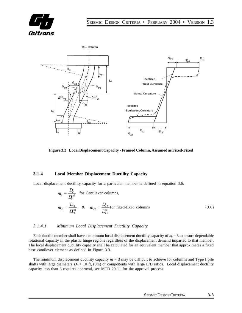
Figure 32 Local Displacement Capacity - Framed Column Assumed as Fixed-Fixed
314 Local Member Displacement Ductility Capacity
Local displacement ductility capacity for a particular member is defined in equation 36
Dc for Cantilever columnsm c = colDY
D Dc1 c2m = amp m = for fixed-fixed columns (36)c1 c2col colD DY 1 Y 2
3141 Minimum Local Displacement Ductility Capacity
Each ductile member shall have a minimum local displacement ductility capacity of mc = 3 to ensure dependable rotational capacity in the plastic hinge regions regardless of the displacement demand imparted to that member The local displacement ductility capacity shall be calculated for an equivalent member that approximates a fixed base cantilever element as defined in Figure 33
The minimum displacement ductility capacity mc = 3 may be difficult to achieve for columns and Type I pile shafts with large diameters Dc gt 10 ft (3m) or components with large LD ratios Local displacement ductility capacity less than 3 requires approval see MTD 20-11 for the approval process
SEISMIC DESIGN CRITERIA 3-3
SECTION 3 - CAPACITIES OF STRUCTURE COMPONENTS
Figure 33 Local Ductility Assessment
SEISMIC DESIGN CRITERIA 3-4
32
SEISMIC DESIGN CRITERIA bull FEBRUARY 2004 bull VERSION 13
Material Properties for Concrete Components
321 Expected Material Properties
The capacity of concrete components to resist all seismic demands except shear shall be based on most probable (expected) material properties to provide a more realistic estimate for design strength An expected concrete compressive strength f cent recognizes the typically conservative nature of concrete batch design and
cethe expected strength gain with age The yield stress f for ASTM A706 steel can range between 60 ksi to 78y ksi An expected reinforcement yield stress f ye is a ldquocharacteristicrdquo strength and better represents the actual strength than the specified minimum of 60 ksi The possibility that the yield stress may be less than in ductilef yecomponents will result in a reduced ratio of actual plastic moment strength to design strength thus conservatively impacting capacity protected components The possibility that the yield stress may be less than in essentiallyf yeelastic components is accounted for in the overstrength magnifier specified in Section 431 Expected material properties shall only be used to assess capacity for earthquake loads The material properties for all other load cases shall comply with the Caltrans Bridge Design Specifications (BDS) Seismic shear capacity shall be conservatively based on the nominal material strengths defined in Section 361 not the expected material strengths
322 Nonlinear Reinforcing Steel Models for Ductile Reinforced Concrete Members
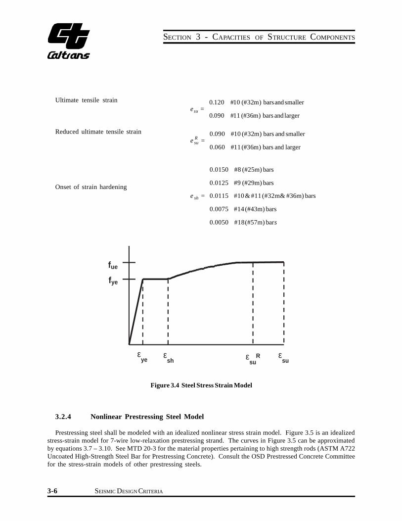
Reinforcing steel shall be modeled with a stress-strain relationship that exhibits an initial linear elastic portion a yield plateau and a strain hardening range in which the stress increases with strain
The yield point should be defined by the expected yield stress of the steel f ye The length of the yield plateau
shall be a function of the steel strength and bar size The strain-hardening curve can be modeled as a parabola or other non-linear relationship and should terminate at the ultimate tensile strain e The ultimate strain should su be set at the point where the stress begins to drop with increased strain as the bar approaches fracture It is Caltransrsquo practice to reduce the ultimate strain by up to thirty-three percent to decrease the probability of fracture of the reinforcement The commonly used steel model is shown in Figure 34 [4]
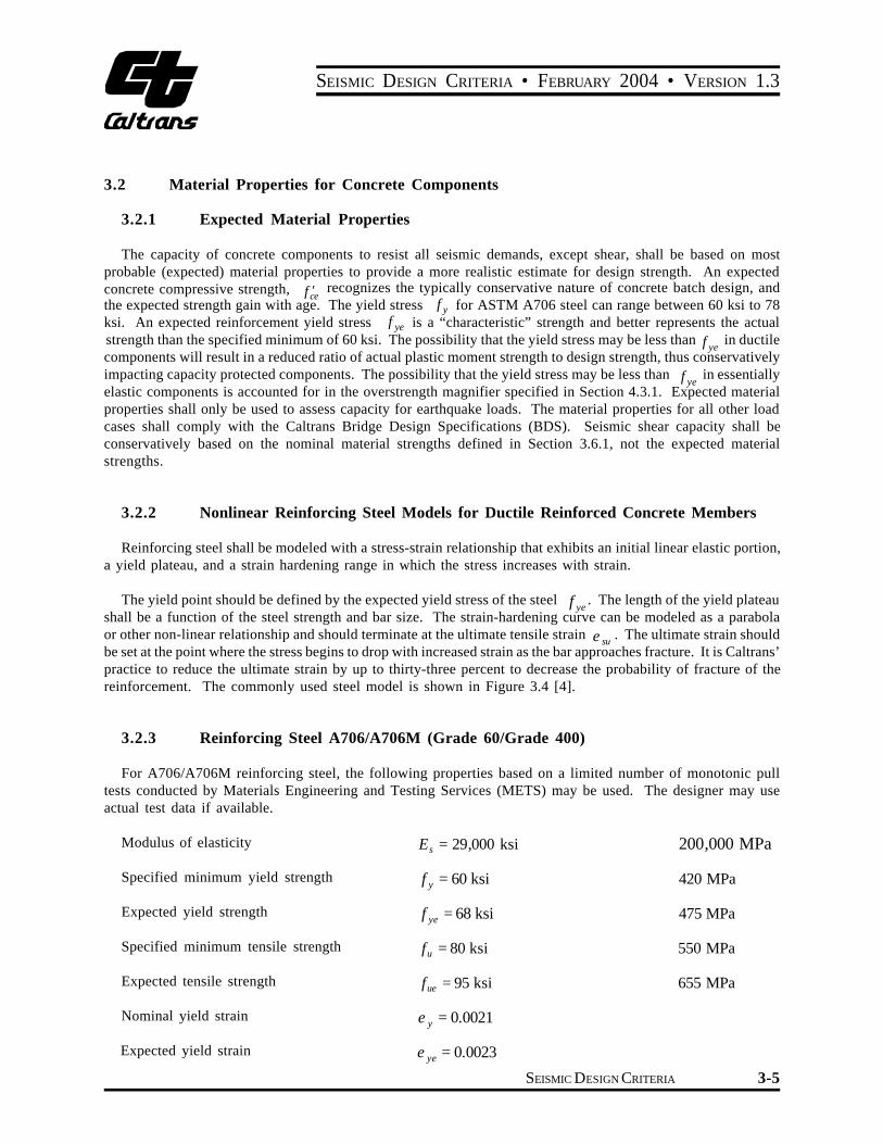
323 Reinforcing Steel A706A706M (Grade 60Grade 400)
For A706A706M reinforcing steel the following properties based on a limited number of monotonic pull tests conducted by Materials Engineering and Testing Services (METS) may be used The designer may use actual test data if available
Modulus of elasticity = sE 29000 ksi 200000 MPa
Specified minimum yield strength = yf 60 ksi 420 MPa
Expected yield strength 68 ksi= yef 475 MPa
Specified minimum tensile strength 80 ksi= uf 550 MPa
Expected tensile strength 95 ksi= uef 655 MPa
Nominal yield strain 00021= ye
Expected yield strain 00023= yee
SEISMIC DESIGN CRITERIA 3-5
SECTION 3 - CAPACITIES OF STRUCTURE COMPONENTS
Ultimate tensile strain =
0120 10 (32m) barsand smaller
0090 11 (36m) bars and larger e su
Reduced ultimate tensile strain
Onset of strain hardening
=
=
0090 10 (32m) bars and smaller
0060 11 (36m) bars and larger
00150 8 (25m) bars
00125 9 (29m) bars
00115 10amp 11(32mamp 36m) bars
00075 14 (43m) bars
00050 18(57m) bars
Re su
e sh
fue
fye
ε ε ε R ε ye sh su su
Figure 34 Steel Stress Strain Model
324 Nonlinear Prestressing Steel Model
Prestressing steel shall be modeled with an idealized nonlinear stress strain model Figure 35 is an idealized stress-strain model for 7-wire low-relaxation prestressing strand The curves in Figure 35 can be approximated by equations 37 ndash 310 See MTD 20-3 for the material properties pertaining to high strength rods (ASTM A722 Uncoated High-Strength Steel Bar for Prestressing Concrete) Consult the OSD Prestressed Concrete Committee for the stress-strain models of other prestressing steels
SEISMIC DESIGN CRITERIA 3-6
SEISMIC DESIGN CRITERIA bull FEBRUARY 2004 bull VERSION 13
Essentially elastic prestress steel strain ps EEe
1 1
11
=
00086
00076
for
for
u
u
f
f
=
=
270 ksi
250 ksi
(1860 MPa)
(1725 MPa )
Reduced ultimate prestress steel strain R psue = 003
250 ksi (1725 MPa) Strand
pspsps f ee middot=pound 2850000076
ps psps f
e e
02525000076 -=Dagger
(ksi)
(ksi)
psf
psf
psemiddot= 196500
pse 1721725 -=
(MPa)
(MPa)
(37)
(38)
270 ksi (1860 MPa) Strand
pspsps f ee middot=pound 2850000086
0007 00427000086 -
-=Dagger ps
psps f e
e
(ksi)
(ksi)
psf
psf
psemiddot= 196500
0007 02761860 -
-= pse
(MPa)
(MPa)
(39)
(310)
270 ksi (1860 MPa)
250 ksi (1725 MPa)
Es = 285000 ksi (1965000 MPa)
270 (1860)
250 (1725)
230 (1585)
210 (1450)
190 (1310)
170 (1170)
150
Stre
ss f p
s ks
i (M
Pa)
(1035) 0 0005 0010 0015 0020 0025 0030
Strain εps
Figure Prestressing Strand Stress Strain35 Model
SEISMIC DESIGN CRITERIA 3-7
SECTION 3 - CAPACITIES OF STRUCTURE COMPONENTS
325 Nonlinear Concrete Models for Ductile Reinforced Concrete Members
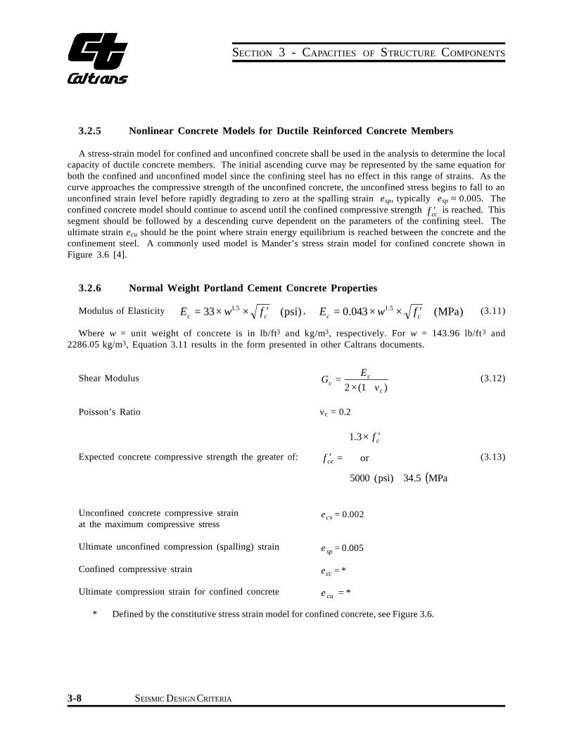
A stress-strain model for confined and unconfined concrete shall be used in the analysis to determine the local capacity of ductile concrete members The initial ascending curve may be represented by the same equation for both the confined and unconfined model since the confining steel has no effect in this range of strains As the curve approaches the compressive strength of the unconfined concrete the unconfined stress begins to fall to an unconfined strain level before rapidly degrading to zero at the spalling strain esp typically esp raquo 0005 The confined concrete model should continue to ascend until the confined compressive strength f cent is reached This cc segment should be followed by a descending curve dependent on the parameters of the confining steel The ultimate strain ecu should be the point where strain energy equilibrium is reached between the concrete and the confinement steel A commonly used model is Manderrsquos stress strain model for confined concrete shown in Figure 36 [4]
326 Normal Weight Portland Cement Concrete Properties
15 15Modulus of Elasticity E = 33middot w middot f cent (psi) E = 0043 middot w middot f cent (MPa) (311)c c c c
Where w = unit weight of concrete is in lbft3 and kgm3 respectively For w = 14396 lbft3 and 228605 kgm3 Equation 311 results in the form presented in other Caltrans documents
EShear Modulus cG =
2 middot (1 c
+ )cv (312)
Poissonrsquos Ratio nc = 02
Expected concrete compressive strength the greater of cent= cef
centmiddot
or
13 cf
(313) 5000 (psi) 345 ( )MPa
Unconfined concrete compressive strain at the maximum compressive stress
0 = ce 0002
Ultimate unconfined compression (spalling) strain = spe 0005
Confined compressive strain cc =e
Ultimate compression strain for confined concrete cue =
Defined by the constitutive stress strain model for confined concrete see Figure 36
SEISMIC DESIGN CRITERIA 3-8
33
SEISMIC DESIGN CRITERIA bull FEBRUARY 2004 bull VERSION 13
f cc
f ce
Unconfined
Confined
ε 2ε ε ε εcuco co sp cc
Figure 36 Concrete Stress Strain Model
327 Other Material Properties
Inelastic behavior shall be limited to pre-determined locations If non-standard components are explicitly designed for ductile behavior the bridge is classified as non-standard The material properties and stress-strain relationships for non-standard components shall be included in the project specific design criteria
Plastic Moment Capacity for Ductile Concrete Members
331 Moment Curvature ( M f-shy ) Analysis
The plastic moment capacity of all ductile concrete members shall be calculated by M -f analysis based on expected material properties Moment curvature analysis derives the curvatures associated with a range of moments for a cross section based on the principles of strain compatibility and equilibrium of forces The M -f curve can be idealized with an elastic perfectly plastic response to estimate the plastic moment capacity of a memberrsquos cross section The elastic portion of the idealized curve should pass through the point marking the first reinforcing bar yield The idealized plastic moment capacity is obtained by balancing the areas between the actual and the idealized M -f curves beyond the first reinforcing bar yield point see Figure 37 [4]
SEISMIC DESIGN CRITERIA 3-9
SECTION 3 - CAPACITIES OF STRUCTURE COMPONENTS
Moment
col Mp
Mne
My
y Y u
Curvature
Figure 37 Moment Curvature Curve
34 Requirements for Capacity Protected Components
Capacity protected concrete components such as footings Type II pile shafts bent cap beams joints and superstructure shall be designed flexurally to remain essentially elastic when the column reaches its overstrength capacity The expected nominal moment capacity M for capacity protected concrete components determinedne by either M -f or strength design is the minimum requirement for essentially elastic behavior Due to cost considerations a factor of safety is not required Expected material properties shall only be used to assess flexural component capacity for resisting earthquake loads The material properties used for assessing all other load cases shall comply with the Caltrans design manuals
Expected nominal moment capacity for capacity protected concrete components shall be based on the expected concrete and steel strengths when either the concrete strain reaches 0003 or the reinforcing steel strain reaches esuR as derived from the steel stress strain model
35 Minimum Lateral Strength
Each column shall have a minimum lateral flexural capacity (based on expected material properties) to resist a lateral force of 01middot Where is the tributary dead load applied at the center of gravity of thePdl Pdlsuperstructure
SEISMIC DESIGN CRITERIA 3-10
)MPa(
)psi(
36
SEISMIC DESIGN CRITERIA bull FEBRUARY 2004 bull VERSION 13
Seismic Shear Design for Ductile Concrete Members
361 Nominal Shear Capacity
The seismic shear demand shall be based on the overstrength shear associated with the overstrength momentVo
M defined in Section 43 The shear capacity for ductile concrete members shall be conservatively based ono the nominal material strengths
fVn Dagger Vo f = 085 (314)
Vn = Vc + Vs (315)
362 Concrete Shear Capacity
The concrete shear capacity of members designed for ductility shall consider the effects of flexure and axial load as specified in equation 316 through 321
Vc = vc middot Ae (316)
Ae = 08middot Ag (317)
bull Inside the plastic hinge zone
Factor1middot Factor 2 middot f ccentpound 4 fccent (psi) (318)vc =
Factor1middot Factor 2 middot f centpound 033 f cent (MPa) c c
bull Outside the plastic hinge zone
3 middot Factor 2 middot fccentpound 4 fccent (psi) v = (319)
c 025 middot Factor 2 middot f c centpound 033 fc cent (MPa)
r f 03 pound s yh + 367- md lt3 (English Units) 0150Factor 1 =
r f (320) s yh0025 pound + 0305- 0083md lt 025 (Metric Units) 125
Pc1 + lt 15 (English Units)2000 middot AgFactor 2 = (321)
Pc 1 + lt 15 (Metric Units)138 middot A g
For members whose net axial load is in tension vc = 0
SEISMIC DESIGN CRITERIA 3-11
SECTION 3 - CAPACITIES OF STRUCTURE COMPONENTS
15
1
0 1000 psi (69 MPa)
30
1
(025)
03 (0025) 2 3 4 5 6
Interpolate
ρsfyh = 0050 Ksi (034 MPa)
ρsfyh = 0350 Ksi (238 MPa)
~
Fa
cto
r 1
Fa
cto
r 2
37 57
Ductility Demand Ratio microd Compressive Axial Stress
Figure 38 Concrete Shear Factors
The global displacement ductility demand mD shall be used in the determination of Factor 1 provided a significant portion of the global displacement is attributed to the deformation of the column or pier In all other cases a local displacement ductility demand md shall be used in Factor 1 of the shear equation
363 Shear Reinforcement Capacity
For confined circular or interlocking core sections
A f D v yh pV = where Av = n Ab (322)
s s Ł 2 łŁ ł
n = number of individual interlocking spiral or hoop core sections
For pier walls (in the weak direction)
A f D v yhV = (323)s sŁ ł
Av = Total area of the shear reinforcement
Alternative methods for assessing the shear capacity of members designed for ductility must be approved through the process outlined in MTD 20-11
364 Deleted
SEISMIC DESIGN CRITERIA 3-12
SEISMIC DESIGN CRITERIA bull FEBRUARY 2004 bull VERSION 13
365 Maximum and Minimum Shear Reinforcement Requirements for Columns
3651 Maximum Shear Reinforcement
The shear strength Vs provided by the reinforcing steel shall not be taken greater than
N8 middot f centA (psi) 067 middot f centA ( ) (324)c e c e 2mm
3652 Minimum Shear Reinforcement
The area of shear reinforcement provided in columns shall be greater than the area required by equation 325 The area of shear reinforcement for each individual core of columns confined by interlocking spirals or hoops shall be greater than the area required by equation 325
Dcent s 2 Dcent s 2Av Dagger 0025 middot (in ) Av Dagger 017 middot (mm ) (325)f fyh yh
3653 Minimum Vertical Reinforcement in Interlocking Portion
The longitudinal rebars in the interlocking portion of the column shall have a maximum spacing of 8 inches and need not be anchored in the footing or the bent cap unless deemed necessary for the flexural capacity of the column The longitudinal rebar size in the interlocking portion of the column shall be chosen correspondingly to the rebars outside the interlocking portion as follows
Size of rebars required inside Size of rebars used outside the interlocking portion the interlocking portion
6 10
8 11
9 14
11 18
366 Shear Capacity of Pier Walls
3661 Shear Capacity in the Weak Direction
The shear capacity for pier walls in the weak direction shall be designed according to Section 362 amp 363
3662 Shear Capacity in the Strong Direction
The shear capacity of pier walls in the strong direction shall resist the maximum shear demand specified in Section 2322
pw pwgt VfVn u (326)
f = 085
SEISMIC DESIGN CRITERIA 3-13
SECTION 3 - CAPACITIES OF STRUCTURE COMPONENTS
Studies of squat shear walls have demonstrated that the large shear stresses associated with the moment capacity of the wall may lead to a sliding failure brought about by crushing of the concrete at the base of the wall The thickness of pier walls shall be selected so the shear stress satisfies equation 327 [6]
pw pwVn Vnlt 8 middot fccent (psi) lt 067 middot fccent (MPa) (327)08 middot Ag 08 middot Ag
367 Shear Capacity of Capacity Protected Members
The shear capacity of essentially elastic members shall be designed in accordance with BDS Section 8166 using nominal material properties
37 Maximum and Minimum Longitudinal Reinforcement
371 Maximum Longitudinal Reinforcement
The area of longitudinal reinforcement for compression members shall not exceed the value specified in equation 328
004 middot Ag(328)
372 Minimum Longitudinal Reinforcement
The minimum area of longitudinal reinforcement for compression members shall not be less than the value specified in equation 329 and 330
001middot AgColumns (329)
0005 middot A Pier Walls (330)g
373 Maximum Reinforcement Ratio
The designer must ensure that members sized to remain essentially elastic (ie superstructure bent caps footings enlarged pile shafts) retain a ductile failure mode The reinforcement ratio r shall meet the requirements in BDS Section 8163 for reinforced concrete members and BDS Section 919 for prestressed concrete members
38 Lateral Reinforcement of Ductile Members
381 Lateral Reinforcement Inside the Analytical Plastic Hinge Length
The volume of lateral reinforcement typically defined by the volumetric ratio provided inside the plasticrshinge length shall be sufficient to ensure the column or pier wall meets the performance requirements in Section 41 for columns with circular or interlocking core sections is defined by equation 331rs
SEISMIC DESIGN CRITERIA 3-14
SEISMIC DESIGN CRITERIA bull FEBRUARY 2004 bull VERSION 13
4Abrs = (331)Dcents
382 Lateral Column Reinforcement Inside the Plastic Hinge Region
The lateral reinforcement required inside the plastic hinge region shall meet the volumetric requirements specified in Section 381 the shear requirements specified in Section 363 and the spacing requirements in Section 825 The lateral reinforcement shall be either butt-welded hoops or continuous spiral3
383 Lateral Column Reinforcement Outside the Plastic Hinge Region
The volume of lateral reinforcement required outside of the plastic hinge region shall not be less than 50 of the amount specified in Section 382 and meet the shear requirements specified in Section 363
384 Lateral Reinforcement of Pier Walls
The lateral confinement of pier walls shall be provided by cross ties The total cross sectional tie area Ash required inside the plastic end regions of pier walls shall be the larger of the volume of steel required in Section 382 or BDS Sections 818232 through 818234 The lateral pier wall reinforcement outside the plastic hinge region shall satisfy BDS Section 81823
385 Lateral Reinforcement Requirements for Columns Supported on Type II Pile Shafts
The volumetric ratio of lateral reinforcement for columns supported on Type II pile shafts shall meet the requirements specified in Section 381 and 382 If the Type II pile shaft is enlarged at least 50 of the confinement reinforcement required at the base of the column shall extend over the entire embedded length of the column cage The required length of embedment for the column cage into the shaft is specified in
Section 824
386 Lateral Confinement for Type II Pile Shafts
The minimum volumetric ratio of lateral confinement in the enlarged Type II shaft shall be 50 of the volumetric ratio required at the base of the column and shall extend along the shaft cage to the point of termination of the column cage
If this results in lateral confinement spacing which violates minimum spacing requirements in the pile shaft the bar size and spacing shall be increased proportionally Beyond the termination of the column cage the volumetric ratio of the Type II pile shaft lateral confinement shall not be less than half that of the upper pile shaft
3 The SDC development team has examined the longitudinal reinforcement buckling issue The maximum spacing requirements in Section 825 should prevent the buckling of longitudinal reinforcement between adjacent layers of transverse reinforcement
SEISMIC DESIGN CRITERIA 3-15
SECTION 3 - CAPACITIES OF STRUCTURE COMPONENTS
Under certain exceptions a Type II shaft may be designed by adding longitudinal reinforcement to a prismatic columnshaft cage below ground Under such conditions the volumetric ratio of lateral confinement in the top segment 4Dcmax of the shaft shall be at least 75 of the confinement reinforcement required at the base of the column
If this results in lateral confinement spacing which violates minimum spacing requirements in the pile shaft the bar size and spacing shall be increased proportionally The confinement of the remainder of the shaft cage shall not be less than half that of the upper pile shaft
SEISMIC DESIGN CRITERIA 3-16
41
SEISMIC DESIGN CRITERIA bull FEBRUARY 2004 bull VERSION 13
4 DEMAND VS CAPACITY
Performance Criteria
411 Global Displacement Criteria
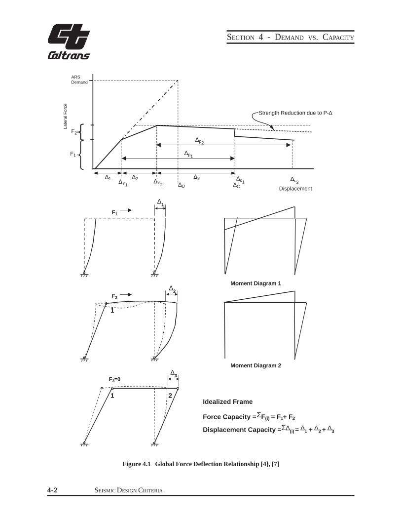
Each bridge or frame shall satisfy equation 41 Where ∆D is the displacement along the local principal axes of a ductile member generated by seismic deformations applied to the structural system as defined in Section 2124
∆D lt ∆C (41)
Where ∆D Is the displacement generated from the global analysis the stand-alone analysis or the larger
of the two if both types of analyses are necessary
∆C The frame displacement when any plastic hinge reaches its ultimate capacity see Figure 41
412 Demand Ductility Criteria
The entire structural system as well as its individual subsystems shall meet the displacement ductility demand requirements in Section 224
413 Capacity Ductility Criteria
All ductile members in a bridge shall satisfy the displacement ductility capacity requirements specified in Section 3141
The SDC development team elected not to include an interaction relationship for the displacement demandcapacity ratios along the principal axes of ductile members This decision was based on the inherent factor of safety provided elsewhere in our practice This factor of safety is provided primarily by the limits placed on permissible column displacement ductility and ultimate material strains as well as the reserve capacity observed in many of the Caltrans sponsored column tests Currently test data is not available to conclusively assess the impact of bi-axial displacement demands and their effects on member capacity especially for columns with large cross sectional aspect ratios
SEISMIC DESIGN CRITERIA 4-1
4
∆c1
SECTION 4 - DEMAND VS CAPACITY
∆p2
∆p1
Strength Reduction due to P-∆
ARS
Demand
La
tera
l F
orc
e
F2
F1
∆3∆1 ∆2
∆C∆D
∆c2∆Y1 ∆Y2
Displacement
∆1
Moment Diagram 1
F1
∆2
F2
1
Moment Diagram 2
∆3
F3=0
1 2 Idealized Frame
Force Capacity =ΣF(i) = F1+ F2
Displacement Capacity =Σ∆ (i) = ∆
1 + ∆ 2 + ∆
3
Figure 41 Global Force Deflection Relationship [4] [7]
SEISMIC DESIGN CRITERIA 4-2
42
43
SEISMIC DESIGN CRITERIA bull FEBRUARY 2004 bull VERSION 13
∆∆ Pshy∆∆∆ Effects
The dynamic effects of gravity loads acting through lateral displacements shall be included in the design The magnitude of displacements associated with P-∆ effects can only be accurately captured with non-linear time history analysis In lieu of such analysis equation 43 can be used to establish a conservative limit for lateral displacements induced by axial load for columns meeting the ductility demand limits specified in Section 224 If equation 43 is satisfied P-∆ effects can typically be ignored5 See Figure 42 [4]
colPdl x ∆r lt 020 x M p (43)
Where ∆r = The relative lateral offset between the point of contra-flexure and the base of the plastic
hinge For Type I pile shafts ∆r = ∆D - ∆s
∆s = The pile shaft displacement at the point of maximum moment
P
L
∆r
V
Plastic Hinge
φ
∆r
V
Plastic Hinge
∆s
Ground Line
∆
My
Mn
Mu
Mp
Mn
Mu
My
Moment at
02Mp
dl Pdl
Co
lum
n H
eig
ht
D Pdl
Figure 42 P-∆∆∆∆∆ Effects on Bridge Columns [4]
Component Overstrength Factors
431 Column Overstrength Factor
In order to determine force demands on essentially elastic members a 20 overstrength magnifier shall be applied to the plastic moment capacity of a column to account for
bull Material strength variations between the column and adjacent members (eg superstructure bent cap footings oversized pile shafts)
bull Column moment capacities greater than the idealized plastic moment capacity
col colM o = 12 x M p (44)
The moment demand at point of maximum moment in the shaft is shown in Figure 42 As the displacement of top of column is increased moment demand values at the base pass through My Mn Mp and Mu (key values defining the moment-curvature curve see Figure 42) The idealized plastic moment Mp is always less than Mu in a well-confined column and 02Mp allowance for the P-Δ effects is justifiable given the reserve moment capacities shown above
SEISMIC DESIGN CRITERIA 4-3
5
SECTION 4 - DEMAND VS CAPACITY
432 SuperstructureBent Cap Demand amp Capacity
The nominal capacity of the superstructure longitudinally and of the bent cap transversely must be sufficient to ensure the columns have moved well beyond their elastic limit prior to the superstructure or bent cap reaching its expected nominal strength M Longitudinally the superstructure capacity shall be greater than the demandne distributed to the superstructure on each side of the column by the largest combination of dead load moment secondary prestress moment and column earthquake moment The strength of the superstructure shall not be considered effective on the side of the column adjacent to a hinge seat Transversely similar requirements are required in the bent cap
Any moment demand caused by dead load or secondary prestress effects shall be distributed to the entire frame The distribution factors shall be based on cracked sectional properties The column earthquake moment represents the amount of moment induced by an earthquake when coupled with the existing column dead load moment and column secondary prestress moment will equal the columnrsquos overstrength capacity see Figure 43 Consequently the column earthquake moment is distributed to the adjacent superstructure spans
sup( R) R R RM ne gesumM dl + M p s + M eq (45)
sup( L) L L LM ne gesumM dl + M p s + M eq (46)
col col col colM = M + M + M (47)o dl p s eq
R L col colM + M + M + (V times D )= 0 (48)eq eq eq o cg
Where
sup R LM = Expected nominal moment capacity of the adjacent left or right superstructure spanne
= Dead load plus added dead load moment (unfactored)M dl
M = Secondary effective prestress moment (after losses have occurred)p s
colM eq = The column moment when coupled with any existing dead load andor secondary prestress
moment will equal the columnrsquos overstrength moment capacity
RL col colM eq = The portion of M and Vo times D (moment induced by the overstrength shear)eq cg
distributed to the left or right adjacent superstructure span
SEISMIC DESIGN CRITERIA 4-4
SEISMIC DESIGN CRITERIA bull FEBRUARY 2004 bull VERSION 13
C ColumnL
Mdl MR
ps
VL
MdlM L
ps
Dcg
Vo col
Mo col
M L
eq M R
eqVR
Note
1 Axial forces not shown
2 Forces shown in positive
counter clockwise sign
convention
Figure 43 Superstructure Demand Generated by Column Overstrength Moment
4321 Longitudinal Superstructure Capacity
Reinforcement can be added to the deck A andor soffit Aprime to increase the moment capacity of the superstructures ssee Figure 44 The effective width of the superstructure increases and the moment demand decreases with distance from the bent cap see Section 7211 The reinforcement should be terminated after it has been developed beyond the point where the capacity of the superstructure M sup exceeds the moment demand without the additionalne reinforcement
4322 Bent Cap Capacity
The effective width for calculating bent cap capacity is defined in section 7311 Bent cap reinforcement required for overstrength must be developed beyond the column cap joint Cutting off bent cap reinforcement is discouraged because small changes in the plastic hinge capacity may translate into large changes in the moment distribution along the cap due to steep moment gradients
C ColumnL
Aps
ε s
εAs cε
φ
CssTs ε εs ps Ccε CpspsTps
Cc TsεsCs
φ
ε c
Stress Strain Strain Stress A s col
Mo col
Vo
Figure 44 Capacity Provided by Superstructure Internal Resultant Force Couple
SEISMIC DESIGN CRITERIA 4-5
SECTION 4 - DEMAND VS CAPACITY
433 Foundation Capacity
The foundation must have sufficient strength to ensure the column has moved well beyond its elastic capacity prior to the foundation reaching its expected nominal capacity refer to Section 62 for additional information on foundation performance
SEISMIC DESIGN CRITERIA 4-6
SEISMIC DESIGN CRITERIA bull FEBRUARY 2004 bull VERSION 13
5 ANALYSIS
51 Analysis Requirements
511 Analysis Objective
The objective of seismic analysis is to assess the force and deformation demands and capacities on the structural system and its individual components Equivalent static analysis and linear elastic dynamic analysis are the appropriate analytical tools for estimating the displacement demands for Ordinary Standard bridges Inelastic static analysis is the appropriate analytical tool to establishing the displacement capacities for Ordinary Standard bridges
52 Analytical Methods
521 Equivalent Static Analysis (ESA)
ESA can be used to estimate displacement demands for structures where a more sophisticated dynamic analysis will not provide additional insight into behavior ESA is best suited for structures or individual frames with well balanced spans and uniformly distributed stiffness where the response can be captured by a predominant translational mode of vibration
The seismic load shall be assumed as an equivalent static horizontal force applied to individual frames The total applied force shall be equal to the product of the ARS and the tributary weight The horizontal force shall be applied at the vertical center of mass of the superstructure and distributed horizontally in proportion to the mass distribution
522 Elastic Dynamic Analysis (EDA)
EDA shall be used to estimate the displacement demands for structures where ESA does not provide an adequate level of sophistication to estimate the dynamic behavior A linear elastic multi-modal spectral analysis utilizing the appropriate response spectrum shall be performed The number of degrees of freedom and the number of modes considered in the analysis shall be sufficient to capture at least 90 mass participation in the longitudinal and transverse directions A minimum of three elements per column and four elements per span shall be used in the linear elastic model
EDA based on design spectral accelerations will likely produce stresses in some elements that exceed their elastic limit The presence of such stresses indicates nonlinear behavior The engineer should recognize that forces generated by linear elastic analysis could vary considerable from the actual force demands on the structure
Sources of nonlinear response that are not captured by EDA include the effects of the surrounding soil yielding of structural components opening and closing of expansion joints and nonlinear restrainer and abutment behavior EDA modal results shall be combined using the complete quadratic combination (CQC) method
Multi-frame analysis shall include a minimum of two boundary frames or one frame and an abutment beyond the frame under consideration See Figure 51
SEISMIC DESIGN CRITERIA 5-1
SECTION 5 - ANALYSIS
523 Inelastic Static Analysis (ISA)
ISA commonly referred to as ldquopush overrdquo analysis shall be used to determine the reliable displacement capacities of a structure or frame as it reaches its limit of structural stability ISA shall be performed using expected material properties of modeled members ISA is an incremental linear analysis which captures the overall nonlinear behavior of the elements including soil effects by pushing them laterally to initiate plastic action Each increment pushes the frame laterally through all possible stages until the potential collapse mechanism is achieved Because the analytical model accounts for the redistribution of internal actions as components respond inelastically ISA is expected to provide a more realistic measure of behavior than can be obtained from elastic analysis procedures
53 Structural System ldquoGlobalrdquo Analysis
Structural system or global analysis is required when it is necessary to capture the response of the entire bridge system Bridge systems with irregular geometry in particular curved bridges and skew bridges multiple transverse expansion joints massive substructures components and foundations supported by soft soil can exhibit dynamic response characteristics that are not necessarily obvious and may not be captured in a separate subsystem analysis [7]
Two global dynamic analyses are normally required to capture the assumed nonlinear response of a bridge because it possesses different characteristics in tension versus compression [3]
In the tension model the superstructure joints including the abutments are released longitudinally with truss elements connecting the joints to capture the effects of the restrainers In the compression model all of the truss (restrainer) elements are inactivated and the superstructure elements are locked longitudinally to capture structural response modes where the joints close up mobilizing the abutments when applicable
The structurersquos geometry will dictate if both a tension model and a compression model are required Structures with appreciable superstructure curvature may require additional models which combine the characteristics identified for the tension and compression models
Long multi-frame bridges shall be analyzed with multiple elastic models A single multi-frame model may not be realistic since it cannot account for out-of-phase movement among the frames and may not have enough nodes to capture all of the significant dynamic modes
Each multi-frame model should be limited to five frames plus a boundary frame or abutment on each end of the model Adjacent models shall overlap each other by at least one useable frame see Figure 51
The boundary frames provide some continuity between adjacent models but are considered redundant and their analytical results are ignored A massless spring should be attached to the dead end of the boundary frames to represent the stiffness of the remaining structure Engineering judgement should be exercised when interpreting the deformation results among various sets of frames since the boundary frame method does not fully account for the continuity of the structure [3]
SEISMIC DESIGN CRITERIA 5-2
SEISMIC DESIGN CRITERIA bull FEBRUARY 2004 bull VERSION 13
Tran 1
Long 2
Long 1
Tran 2
Boundary Frame 3
Boundary Frame 2
Tran 3
Long 3
Boundary Frame 2
Boundary Frame 1
Legend
Long Longitudinal Axis
Abut
Abut
Model 1
Model 2
Model 3
Tran Transverse Axis
Bridge Expansion Joint
Figure 51 EDA Modeling Techniques
54 Stand-Alone ldquoLocalrdquo Analysis
Stand-alone analysis quantifies the strength and ductility capacity of an individual frame bent or column Standshyalone analysis shall be performed in both the transverse and longitudinal directions Each frame shall meet all SDC requirements in the stand-alone condition
541 Transverse Stand-Alone Analysis
Transverse stand-alone frame models shall assume lumped mass at the columns Hinge spans shall be modeled as rigid elements with half of their mass lumped at the adjacent column see Figure 52 The transverse analysis of end frames shall include a realistic estimate of the abutment stiffness consistent with the abutmentrsquos expected performance The transverse displacement demand at each bent in a frame shall include the effects of rigid body rotation around the framersquos center of rigidity
SEISMIC DESIGN CRITERIA 5-3
55
SECTION 5 - ANALYSIS
542 Longitudinal Stand-Alone Analysis
Longitudinal stand-alone frame models shall include the short side of hinges with a concentrated dead load and the entire long side of hinges supported by rollers at their ends see Figure 52 Typically the abutment stiffness is ignored in the stand-alone longitudinal model for structures with more than two frames an overall length greater than 300 feet (90 m) or significant in plane curvature since the controlling displacement occurs when the frame is moving away from the abutment A realistic estimate of the abutment stiffness may be incorporated into the stand-alone analysis for single frame tangent bridges and two frame tangent bridges less than 300 feet (90 m) in length
Simplified Analysis
The two-dimensional plane frame ldquopush overrdquo analysis of a bent or frame can be simplified to a column model (fixedshyfixed or fixed-pinned) if it does not cause a significant loss in accuracy in estimating the displacement demands or the displacement capacities The effect of overturning on the column axial load and associated member capacities must be considered in the simplified model Simplifying the demand and capacity models is not permitted if the structure does not meet the stiffness and period requirements in Sections 711 and 712
Figure 52 Stand-Alone Analysis
SEISMIC DESIGN CRITERIA 5-4
56
SEISMIC DESIGN CRITERIA bull FEBRUARY 2004 bull VERSION 13
Effective Section Properties
561 Effective Section Properties for Seismic Analysis
Elastic analysis assumes a linear relationship between stiffness and strength Concrete members display nonlinear response before reaching their idealized Yield Limit State
Section properties flexural rigidity Ec I and torsional rigidity Gc J shall reflect the cracking that occurs before the yield limit state is reached The effective moments of inertia and shall be used to obtain realistic valuesI eff J efffor the structurersquos period and the seismic demands generated from ESA and EDA analyses
5611 Ieff for Ductile Members
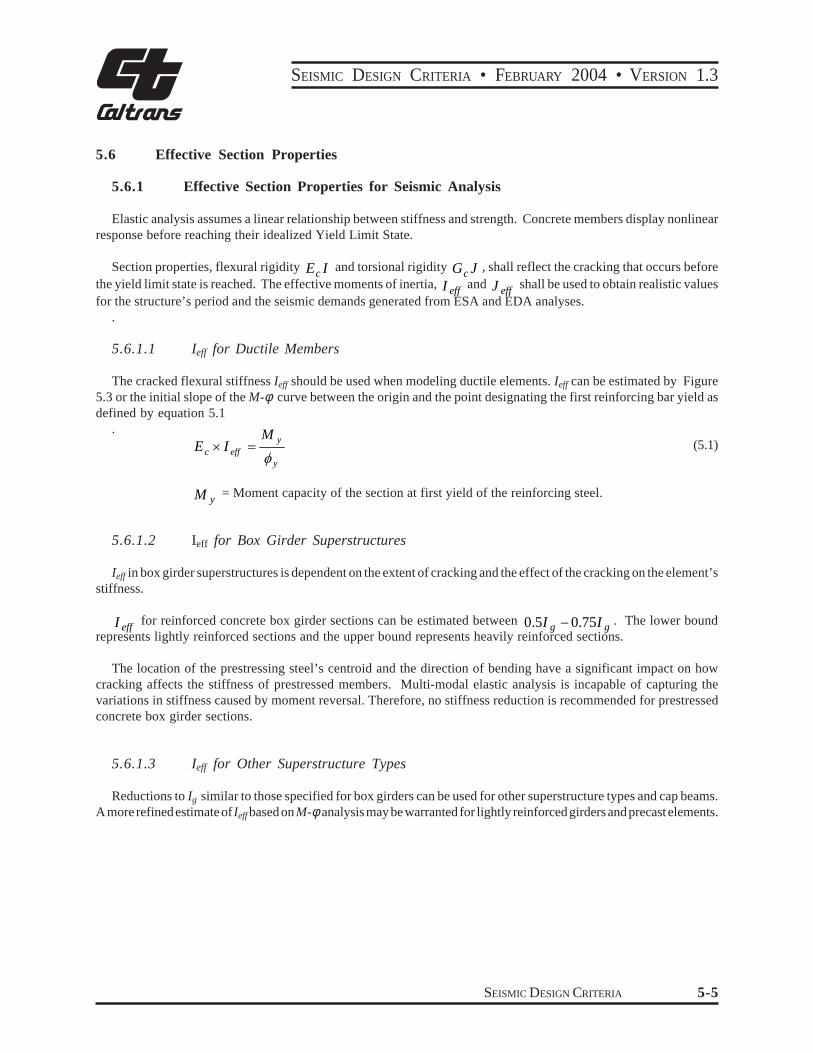
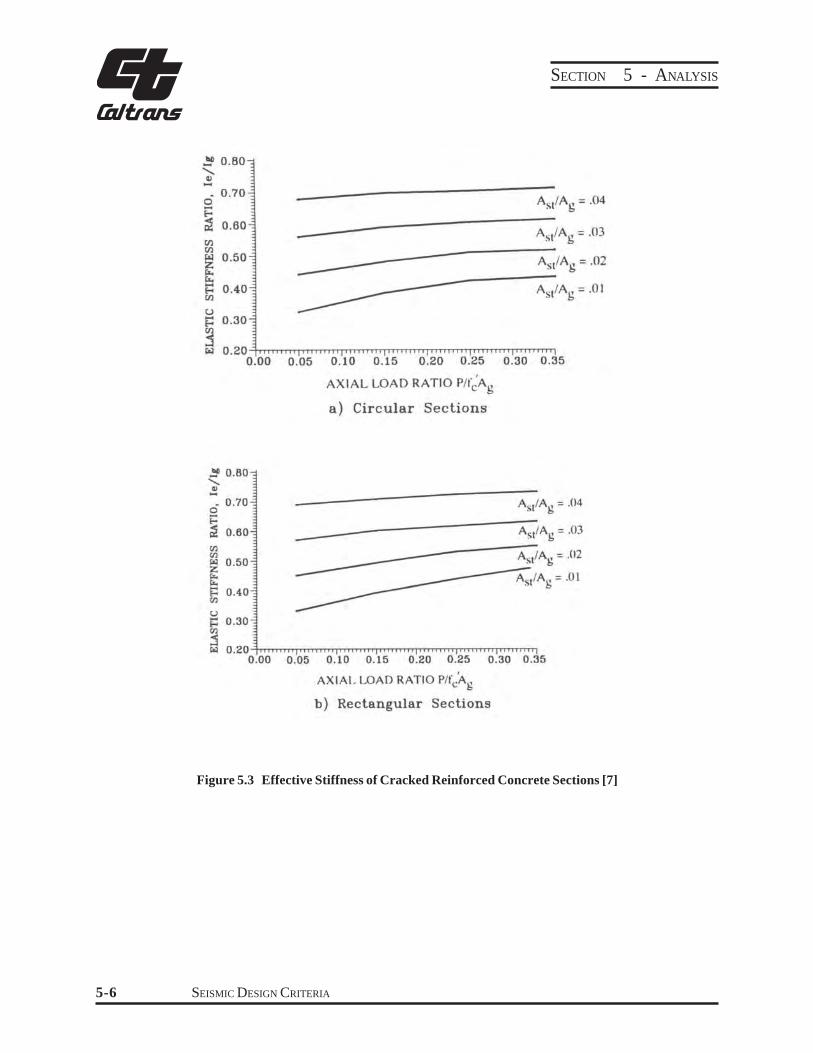
The cracked flexural stiffness Ieff should be used when modeling ductile elements Ieff can be estimated by Figure 53 or the initial slope of the M-φ curve between the origin and the point designating the first reinforcing bar yield as defined by equation 51
M E times I =
y (51)c eff φ y
M = Moment capacity of the section at first yield of the reinforcing steely
5612 Ieff for Box Girder Superstructures
Ieff in box girder superstructures is dependent on the extent of cracking and the effect of the cracking on the elementrsquos stiffness
I eff for reinforced concrete box girder sections can be estimated between 05I g minus 075I g The lower bound represents lightly reinforced sections and the upper bound represents heavily reinforced sections
The location of the prestressing steelrsquos centroid and the direction of bending have a significant impact on how cracking affects the stiffness of prestressed members Multi-modal elastic analysis is incapable of capturing the variations in stiffness caused by moment reversal Therefore no stiffness reduction is recommended for prestressed concrete box girder sections
5613 Ieff for Other Superstructure Types
Reductions to Ig similar to those specified for box girders can be used for other superstructure types and cap beams A more refined estimate of Ieff based on M-φanalysis may be warranted for lightly reinforced girders and precast elements
SEISMIC DESIGN CRITERIA 5-5
SECTION 5 - ANALYSIS
Figure 53 Effective Stiffness of Cracked Reinforced Concrete Sections [7]
SEISMIC DESIGN CRITERIA 5-6
SEISMIC DESIGN CRITERIA bull FEBRUARY 2004 bull VERSION 13
562 Effective Torsional Moment of Inertia
A reduction of the torsional moment of inertia is not required for bridge superstructures that meet the Ordinary Bridge requirements in Section 11 and do not have a high degree of in-plane curvature [7]
The torsional stiffness of concrete members can be greatly reduced after the onset of cracking The torsional moment of inertia for columns shall be reduced according to equation 52
(52)J = 02 times Jeff g
57 Effective Member Properties for Non-Seismic Loading
Temperature and shortening loads calculated with gross section properties may control the column size and strength capacity often penalizing seismic performance If this is the case the temperature or shortening forces should be recalculated based on the effective moment of inertia for the columns
SEISMIC DESIGN CRITERIA 5-7
61
SEISMIC DESIGN CRITERIA bull FEBRUARY 2004 bull VERSION 13
6 SEISMICITY AND FOUNDATION PERFORMANCE
Site Assessment
611 Seismicity and Foundation Data
The geotechnical engineer shall provide the following geotechnical data See MTD 1-35 for information on requesting foundation data
bull Seismicity
minus Fault distance
minus Earthquake magnitude
minus Peak rock acceleration
minus Soil profile type
bull Liquefaction potential
bull Foundation stiffness or the soil parameters necessary for determining the force deformation characteristics of the foundation (when required)
612 ARS Curves
The geotechnical engineer will assess each bridge site and will recommend one of the following a standard 5 damped SDC ARS curve a modified SDC ARS curve or a site-specific ARS curve The final seismic design recommendations shall be included in the Final Foundation Report
6121 Standard ARS Curves
For preliminary design prior to receiving the geotechnical engineerrsquos recommendation a standard SDC ARS curve may be used in conjunction with the peak rock acceleration from the 1996 Caltrans Seismic Hazard Map The standard SDC ARS curves are contained in Appendix B If standard SDC ARS curves are used during preliminary design they should be adjusted for long period bridges and bridges in close proximity to a fault as described below
For preliminary design of structures within 10 miles (15 km) of an active fault the spectral acceleration on the SDC ARS curves shall be magnified as follows
bull Spectral acceleration magnification is not required for T le 05 seconds
bull Increase the spectral accelerations for T ge 10 seconds by 20
bull Spectral accelerations for 05 le T le 10 shall be determined by linear interpolation
SEISMIC DESIGN CRITERIA 6-1
62
SECTION 6 - SEISMICITY AND FOUNDATION PERFORMANCE
For preliminary design of structures with a fundamental period of vibration T ge15 seconds on deep soil sites (depth of alluvium ge 250 feet 75 m) the spectral ordinates of the standard ARS curve should be magnified as follows
bull Spectral acceleration magnification is not required for T le 05 seconds
bull Increase the spectral accelerations for T ge 15 seconds by 20
bull Spectral accelerations for 05 le T le 15 shall be determined by linear interpolation
6122 Site Specific ARS Curves
Geotechnical Services (GS) will determine if a site-specific ARS curve is required A site specific response spectrum is typically required when a bridge is located in the vicinity of a major fault or located on soft or liquefiable soil and the estimated earthquake moment magnitude M m gt 65
The rock motion and soil profile can vary significantly along the length of long bridges Consult with GS on bridges exceeding 1000 feet (300 m) in length to assess the probability of non-synchronous ground motion and the impact of different subsurface profiles along the length of the bridge
The use of free field ground surface response spectra may not be appropriate for structures with stiff pile foundations in soft soil or deep pileshafts in soft soil extending into bedrock Special analysis is required because of soil-pile kinematic interaction and shall be addressed by the geotechnical engineer on a job specific basis
Foundation Design
621 Foundation Performance
bull Bridge foundations shall be designed to respond to seismic loading in accordance with the seismic performance objectives outlined in MTD 20-1
bull The capacity of the foundations and their individual components to resist MCE seismic demands shall be based on ultimate structural and soil capacities
622 Soil Classification6
The soil surrounding and supporting a foundation combined with the structural components (ie piles footings pile caps amp drilled shafts) and the seismic input loading determines the dynamic response of the foundation subsystem Typically the soil response has a significant effect on the overall foundation response Therefore we can characterize
Section 62 contains interim recommendations The Caltransrsquo foundation design policy is currently under review Previous practice essentially divided soil into two classifications based on standard penetration Lateral foundation design was required in soft soil defined by N le 10 The SDC includes three soil classifications competent marginal and poor The marginal classification recognizes that it is more difficult to assess intermediate soils and their impact on dynamic response compared to the soils on the extreme ends of the soil spectrum (ie very soft or very firm)
The SDC development team recognizes that predicting the soil and foundation response with a few selected geotechnical parameters is simplistic and may not adequately capture soil-structure interaction (SSI) in all situations The designer must exercise engineering judgement when assessing the impact of marginal soils on the overall dynamic response of a bridge and should consult with Geotechnical Services and Structure Design senior staff if they do not have the experience andor the information required to make the determination themselves
SEISMIC DESIGN CRITERIA 6-2
6
SEISMIC DESIGN CRITERIA bull FEBRUARY 2004 bull VERSION 13
the foundation subsystem response based on the quality of the surrounding soil Soil can be classified as competent poor or marginal as described in Section 623 (A) (B) amp (C) Contact the Project GeologistGeotechnical Engineer if it is uncertain which soil classification pertains to a particular bridge site
622(A) Competent Soil
Foundations surrounded by competent soil are capable of resisting MCE level forces while experiencing small deformations This type of performance characterizes a stiff foundation subsystem that usually has an insignificant impact on the overall dynamic response of the bridge and is typically ignored in the demand and capacity assessment Foundations in competent soil can be analyzed and designed using a simple model that is based on assumptions consistent with observed response of similar foundations during past earthquakes Good indicators that a soil is capable of producing competent foundation performance include the following
bull Standard penetration upper layer (0-10 ft 0-3 m) N = 20 (Granular soils)
bull Standard penetration lower layer (10-30 ft 3-9 m) N = 30 (Granular soils)
bull Undrained shear strength su gt 1500 psf (72 KPa) (Cohesive soils)
bull Shear wave velocity ν gt 600 ft (180 m )s sec sec bull Low potential for liquefaction lateral spreading or scour
N = The uncorrected blow count from the Standard Test Method for Penetration Test and Split- Barrel Sampling of Soil
622(B) Poor Soil
Poor soil has traditionally been characterized as having a standard penetration Nlt10 The presence of poor soil classifies a bridge as non-standard thereby requiring project-specific design criteria that address soil structure interaction (SSI) related phenomena SSI mechanisms that should be addressed in the project criteria include earth pressure generated by lateral ground displacement dynamic settlement and the effect of foundation flexibility on the response of the entire bridge The assumptions that simplify the assessment of foundation performance in competent soil cannot be applied to poor soil because the lateral and vertical force-deformation response of the soil has a significant effect on the foundation response and subsequently on the overall response of the bridge
622(C) Marginal Soil
Marginal defines the range on soil that cannot readily be classified as either competent or poor The course of action for bridges in marginal soil will be determined on a project-by-project basis If a soil is classified as marginal the bridge engineer and foundation designer shall jointly select the appropriate foundation type determine the impact of SSI and determine the analytical sophistication required to reasonably capture the dynamic response of the foundation as well as the overall dynamic response of the bridge
SEISMIC DESIGN CRITERIA 6-3
SECTION 6 - SEISMICITY AND FOUNDATION PERFORMANCE
623 Foundation Design Criteria
6231 Foundation Strength
All foundations shall be designed to resist the plastic hinging overstrength capacity of the column or pier wall M o defined in Section 431 and the associated plastic shear V 7 See Section 77 for additional foundation designo guidelines
6232 Foundation Flexibility
The demand and capacity analyses shall incorporate the expected foundation stiffness if the bridge is sensitive to variations in rotational vertical or lateral stiffness
7 An exception is permitted for pile cap and spread footing foundations in competent soil where the foundation may be designed for M p
in lieu of M Designing for a smaller column capacity is justified because of additional capacity inherent to these typesoof foundation systems that is not typically included in the foundation capacity assessment
6-4 SEISMIC DESIGN CRITERIA
71
SEISMIC DESIGN CRITERIA bull FEBRUARY 2004 bull VERSION 13
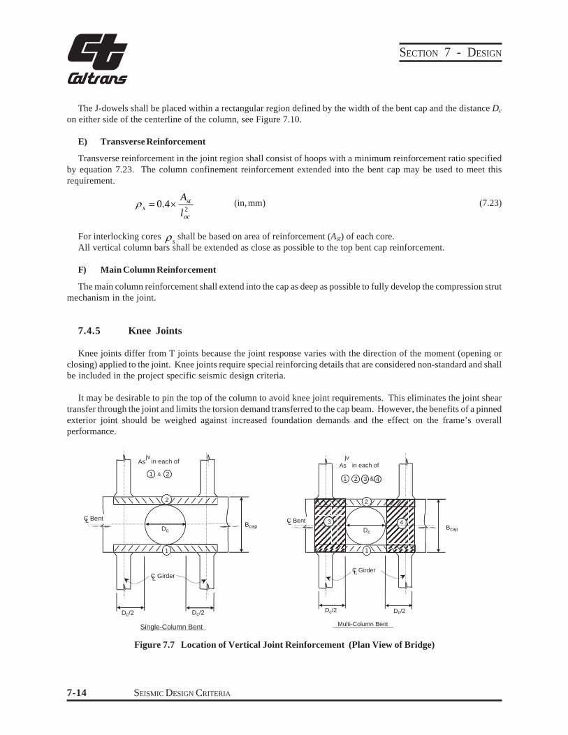
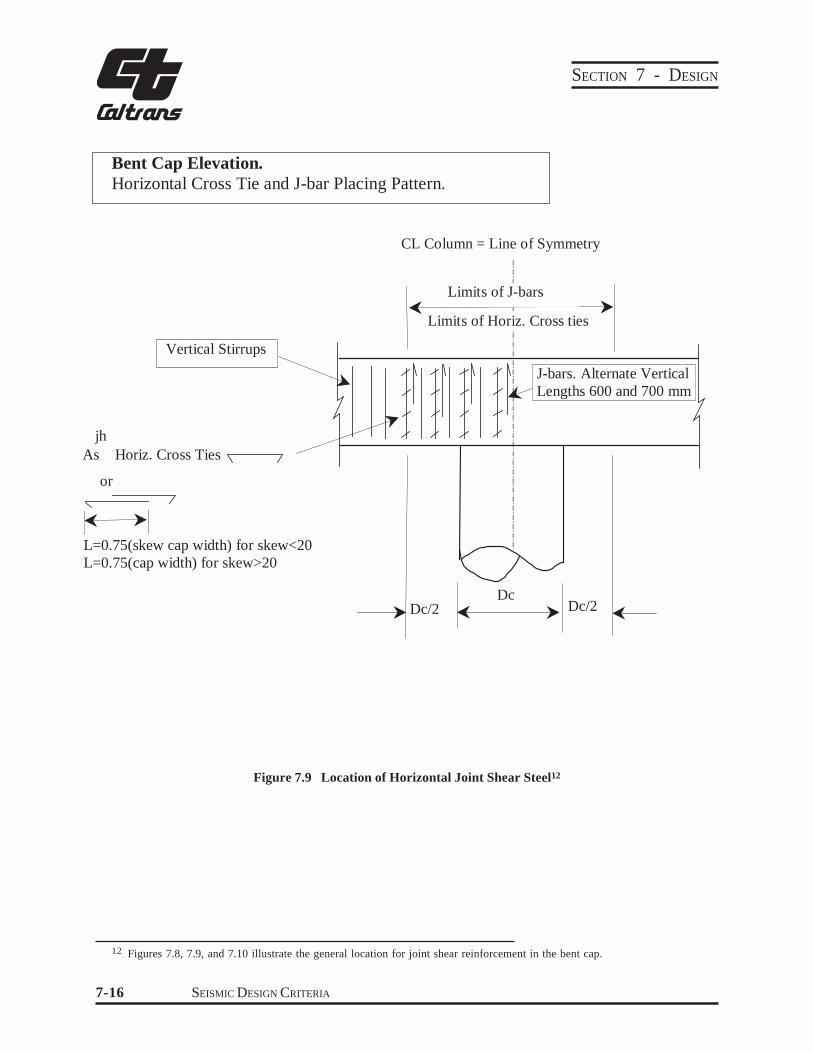
7 DESIGN
Frame Design
The best way to increase a structurersquos likelihood of responding to seismic attack in its fundamental mode of vibration is to balance its stiffness and mass distribution Irregularities in geometry increase the likelihood of complex nonlinear response that cannot be accurately predicted by elastic modeling or plane frame inelastic static modeling
711 Balanced Stiffness
It is strongly recommended that the ratio of effective stiffness between any two bents within a frame or between any two columns within a bent satisfy equation 71 It is strongly recommended that the ratio of effective stiffness between adjacent bents within a frame or between adjacent columns within a bent satisfy equation 72 An increase in superstructure mass along the length of the frame should be accompanied by a reasonable increase in column stiffness For variable width frames the tributary mass supported by each bent or column shall be included in the stiffness comparisons as specified by equation 71(b) and 72(b) The simplified analytical technique for calculating frame capacity described in Section 55 is only permitted if either 71(a) amp 72(a) or 71(b) amp 71(b) are satisfied
Constant Width Frames Variable Width Frames
50gee j
e i
k k (71a)
j
e j
i
e i
m
k m
k
750gee j
e i
k k (72a)
j
e j
i
e i
m
k m
k
ge 05 (71b)
ge 075 (72b)
eki = The smaller effective bent or mi = Tributary mass of column or bent i
column stiffness
ek j = The larger effective bent or mj = Tributary mass of column or bent j column stiffness
The following considerations shall be taken into account when calculating effective stiffness framing effects end conditions column height percentage of longitudinal and transverse column steel column diameter and foundation flexibility Some of the consequences of not meeting the relative stiffness recommendations defined by equations 71 and 72 include
SEISMIC DESIGN CRITERIA 7-1
SECTION 7 - DESIGN
j
i T
T
bull Increased damage in the stiffer elements
bull An unbalanced distribution of inelastic response throughout the structure
bull Increased column torsion generated by rigid body rotation of the superstructure
712 Balanced Frame Geometry
It is strongly recommend that the ratio of fundamental periods of vibration for adjacent frames in the longitudinal and transverse direction satisfy equation 73
ge 07 (73)
Ti = Natural period of the less flexible frame
Tj = Natural period of the more flexible frame
The consequences of not meeting the fundamental period requirements of equation 73 include a greater likelihood of out-of-phase response between adjacent frames leading to large relative displacements that increase the probability of longitudinal unseating and collision between frames at the expansion joints The colliding and relative transverse translation of adjacent frames will transfer the seismic demand from one frame to the next which can be detrimental to the stand-alone capacity of the frame receiving the additional seismic demand
713 Adjusting Dynamic Characteristics
The following list of techniques should be considered for adjusting the fundamental period of vibration andor stiffness to satisfy equations 71 72 and 73 Refer to Memo to Designer 6-1 for additional information on optimizing performance of bridge frames
bull Oversized pile shafts
bull Adjust effective column lengths (ie lower footings isolation casing)
bull Modified end fixities
bull Reduceredistribute superstructure mass
bull Vary the column cross section and longitudinal reinforcement ratios
bull Add or relocate columns
bull Modify the hingeexpansion joint layout
bull Incorporate isolation bearings or dampers
A careful evaluation of the local ductility demands and capacities is required if project constraints make it impractical to satisfy the stiffness and structure period requirements in equations 71 72 and 73
714 End Span Considerations
The influence of the superstructure on the transverse stiffness of columns near the abutment particularly when calculating shear demand shall be considered
SEISMIC DESIGN CRITERIA 7-2
SEISMIC DESIGN CRITERIA bull FEBRUARY 2004 bull VERSION 13
FRAME 1 FRAME 2
BENT 2
BENT 3
BENT 4
BENT 6
BENT 5
T1 T2
m2 m5m3 m4 m6
k2
k3 k4 k5
k6
BENT 3
k2 k1
Figure 71 Balanced Stiffness
SEISMIC DESIGN CRITERIA 7-3
SECTION 7 - DESIGN
72 Superstructure
721 Girders
7211 Effective Superstructure Width
The effective width of superstructure resisting longitudinal seismic moments is defined by equation 74 The effective width for open soffit structures (eg T-Beams amp I- Girders) is reduced because they offer less resistance to the torsional rotation of the bent cap The effective superstructure width can be increased at a 45ο angle as you move away from the bent cap until the full section becomes effective On skewed bridges the effective width shall be projected normal to the girders where the centerline of girder intersects the face of the bent cap See Figure 72
Dc + 2 times Ds Box girders amp solid superstructuresB = (74)eff D + Ds c Open soffit superstructures
Additional superstructure width can be considered effective if the designer verifies the torsional capacity of the cap can distribute the rotational demands beyond the effective width stated in equation 74
If the effective width cannot accommodate enough steel to satisfy the overstrength requirements of Section 431 the following actions may be taken
bull Thicken the soffit andor deck slabs
bull Increase the resisting section by widening the column
bull Haunch the superstructure
bull Add additional columns
The benefit of using wider columns must be carefully weighed against the increased joint shear demands and larger plastic hinging capacity
Isolated or lightly reinforced flares shall be ignored when calculating the effective superstructure width See Section 765 for additional information on flare design
722 Vertical Acceleration
If vertical acceleration is considered per Section 21 a separate analysis of the superstructurersquos nominal capacity shall be performed based on a uniformly applied vertical force equal to 25 of the dead load applied upward and downward see Figure 73 The superstructure at seat type abutment is assumed to be pinned in the vertical direction up or down The superstructure flexural capacity shall be based only on continuous mild reinforcement distributed evenly between the top and bottom slabs The effects of dead load primary and secondary prestressing shall be ignored The continuous steel shall be spliced with ldquoservice levelrdquo couplers as defined in Section 813 and is considered effective in offsetting the mild reinforcement required for other load cases Lap splices equal to two times the standard lap may be substituted for the ldquoservice splicesrdquo provided the laps are placed away from the critical zones (mid-spans and near supports)
SEISMIC DESIGN CRITERIA 7-4
L
SEISMIC DESIGN CRITERIA bull FEBRUARY 2004 bull VERSION 13
C of BentL
Beff
45 Typ
Beff =Dc + 2xDs
C of Girder Ds
Tangent Bridges Dc
Beff
45 Typ
Beff =Dc + Ds
Ds
C of GirderL
Dc
C of BentL
Skewed Bridges
Figure 72 Effective Superstructure Width
Equivalent Static Positive Vertical Load = (025 x DL)
Equivalent Positive Vertical Moment
Equivalent Static Negative Vertical Load = (025 x DL)
Equivalent Negative Vertical Moment
Figure 73 Equivalent Static Vertical Loads amp Moments
SEISMIC DESIGN CRITERIA 7-5
SECTION 7 - DESIGN
The longitudinal side reinforcement in the girders if vertical acceleration is considered per Section 21 shall be capable of resisting 125 of the dead load shear at the bent face by means of shear friction The enhanced side reinforcement shall extend continuously for a minimum of 25 Ds beyond the face of the bent cap
723 Pre-cast Girders
Historically precast girders lacked a direct positive moment connection between the girders and the cap beam which could potentially degrade to a pinned connection in the longitudinal direction under seismic demands Therefore to provide stability under longitudinal seismic demands columns shall be fixed at the base unless an integral girdercap beam connection is provided that is capable of resisting the column overstrength demands as outlined in Sections 431 432 amp 722 Recent research has confirmed the viability of pre-cast spliced girders with integral column superstructure details that effectively resist longitudinal seismic loads This type of system is considered non-standard until design details and procedures are formally adopted In the interim project specific design criteria shall be developed per MTD 20-11
724 Slab Bridges
Slab bridges shall be designed to meet all the strength and ductility requirements as specified in the SDC
725 Hinges
7251 Longitudinal Hinge Performance
Intermediate hinges are necessary for accommodating longitudinal expansion and contraction resulting from prestress shortening creep shrinkage and temperature variations The hinge allows each frame to vibrate indepenshydently during an earthquake Large relative displacements can develop if the vibrations of the frames are out-of-phase Sufficient seat width must be provided to prevent unseating
7252 Transverse Hinge Performance
Typically hinges are expected to transmit the lateral shear forces generated by small earthquakes and service loads Determining the earthquake force demand on shear keys is difficult since the magnitude is dependent on how much relative displacement occurs between the frames Forces generated with EDA should not be used to size shear keys EDA overestimates the resistance provided by the bents and may predict force demands on the shear keys that differ significantly from the actual forces
7253 Frames Meeting the Requirements of Section 712
All frames including balanced frames or frames with small differences in mass andor stiffness will exhibit some outshyof-phase response The objective of meeting the fundamental period recommendations between adjacent frames presented in Section 712 is to reduce the relative displacements and associated force demands attributed to out-ofshyphase response
Longitudinal Requirements
For frames adhering to Section 712 and expected to be exposed to synchronous ground motion the minimum longitudinal hinge seat width between adjacent frames shall be determined by Section 7254
SEISMIC DESIGN CRITERIA 7-6
SEISMIC DESIGN CRITERIA bull FEBRUARY 2004 bull VERSION 13
Transverse Requirements
The shear key shall be capable of transferring the shear between adjacent frames if the shear transfer mechanism is included in the demand assessment The upper bound for the transverse shear demand at the hinge can be estimated by the sum of the overstrength shear capacity of all the columns in the weaker frame The shear keys must have adequate capacity to meet the demands imposed by service loads
An adequate gap shall be provided around the shear keys to eliminate binding of the hinge under service operation and to ensure lateral rotation will occur thereby minimizing moment transfer across the expansion joint
Although large relative displacements are not anticipated for frames with similar periods exposed to synchronous ground motion certain structural configurations may be susceptible to lateral instability if the transverse shear keys completely fail Particularly skewed bridges bridges with three or less girders and narrow bridges with significant super elevation Additional restraint such as XX strong pipe keys should be considered if stability is questionable after the keys are severely damaged
7254 Hinge Seat Width for Frames Meeting the Requirements of Section 712
Enough hinge seat width shall be available to accommodate the anticipated thermal movement prestress shortening creep shrinkage and the relative longitudinal earthquake displacement demand between the two frames calculated by equation 76 The seat width normal to the centerline of bearing shall be calculated by equation 75 but not less than 24 inches (600 mm)
(∆ p s + ∆cr +sh + ∆ + ∆ + 4) (in) temp eqN ge (75)(∆ p s + ∆cr +sh + ∆temp + ∆eq +100) (mm)
N = Minimum seat width normal to the centerline of bearing
∆p = Displacement attributed to pre-stress shortenings
∆ = Displacement attributed to creep and shrinkagecr+sh
∆ = Displacement attributed to thermal expansion and contractiontemp
∆ eq = Relative earthquake displacement demand
21 2∆ = (∆ ) + (∆ )2 (76)eq D D
∆(Di) = The larger earthquake displacement demand for each frame calculated by the global
or stand-alone analysis
4rdquo (100mm) ∆eq∆ps+ ∆ cr+sh+∆temp
N
Seat ge 24 in (600 mm)
Figure 74 Seat Width Requirements
SEISMIC DESIGN CRITERIA 7-7
SECTION 7 - DESIGN
7255 Frames Not Meeting the Requirements of Section 712
Frames that are unbalanced relative to each other have a greater likelihood of responding out-of-phase during earthquakes Large relative displacements and forces should be anticipated for frames not meeting equation 73
Elastic Analysis in general cannot be used to determine the displacement or force demands at the intermediate expansion joints in multi-frame structures A more sophisticated analysis such as nonlinear dynamic analysis is required that can capture the directivity and time dependency associated with the relative frame displacements In lieu of nonlinear analysis the hinge seat can be sized longitudinally and the shear keys isolated transversely to accommodate the absolute sum of the individual frame displacements determined by ESA EDA or the initial slope of a ldquopush overrdquo analysis
Care must be taken to isolate unbalanced frames to insure the seismic demands are not transferred between frames The following guidelines should be followed when designing and detailing hinges when equation 73 is not met
bull Isolate adjacent frames longitudinally by providing a large expansion gap to reduce the likelihood of pounding Permanent gapping created by prestress shortening creep and shrinkage can be considered as part of the isolation between frames
bull Provide enough seat width to reduce the likelihood of unseating If seat extenders are used they should be isolated transversely to avoid transmitting large lateral shear forces between frames
bull Limit the transverse shear capacity to prevent large lateral forces from being transferred to the stiffer frame The analytical boundary conditions at the hinge should be either released transversely or able to capture the nonlinear shear friction mechanism expected at the shear key If the hinges are expected to fail the column shall be designed to accommodate the displacement demand associated with having the hinge released transversely
One method for isolating unbalanced frames is to support intermediate expansion joints on closely spaced adjacent bents that can support the superstructure by cantilever beam action A longitudinal gap is still required to prevent the frames from colliding Bent supported expansion joints need to be approved on a project-by-project basis see MTD 20-11
726 Hinge Restrainers
A satisfactory method for designing the size and number of restrainers required at expansion joints is not currently available Adequate seat shall be provided to prevent unseating as a primary requirement Hinge restrainers are considered secondary members to prevent unseating The following guidelines shall be followed when designing and detailing hinge restrainers
bull Restrainers design should not be based on the force demands predicted by EDA analysis
bull A restrainer unit shall be placed in each alternating cell at all hinges (minimum of two restrainer units at each hinge)
bull Restrainers shall be detailed to allow for easy inspection and replacement
bull Restrainer layout shall be symmetrical about the centerline of the superstructure
bull Restrainer systems shall incorporate an adequate gap for expansion
SEISMIC DESIGN CRITERIA 7-8
SEISMIC DESIGN CRITERIA bull FEBRUARY 2004 bull VERSION 13
Yield indicators are required on all cable restrainers see Standard Detail Sheet XS 12-571 for details See MTD 20-3 for material properties pertaining to high strength rods (ASTM A722 Uncoated High-Strength Steel Bar for Prestressing Concrete) and restrainer cables (ASTM A633 Zinc Coated Steel Structural Wire Rope)
727 Pipe Seat Extenders
Pipes seat extenders shall be designed for the induced moments under single or double curvature depending on how the pipe is anchored If the additional support width provided by the pipe seat extender is required to meet equation 75 then hinge restrainers are still required If the pipe seat extenders are provided as a secondary vertical support system above and beyond what is required to satisfy equation 75 hinge restrainers are not required Pipe seat extenders will substantially increase the shear transfer capacity across expansion joints if significant out-of-phase displacements are anticipated If this is the case care must be taken to insure stand-alone frame capacity is not adversely affected by the additional demand transmitted between frames through the pipe seat extenders
728 Equalizing Bolts
Equalizing bolts are designed for service loads and are considered sacrificial during an earthquake Equalizing bolts shall be designed so they will not transfer seismic demand between frames or inhibit the performance of the hinge restrainers Equalizing bolts shall be detailed so they can be easily inspected for damage andor replaced after an earthquake
73 Bent Caps
731 Integral Bent Caps
Bent caps are considered integral if they terminate at the outside of the exterior girder and respond monolithically with the girder system during dynamic excitation
7311 Effective Bent Cap Width
The integral cap width considered effective for resisting flexural demands from plastic hinging in the columns shall be determined by equation 77 See Figure 75
Beff =Bcap +(12 times t) (77)
t = Thickness of the top or bottom slabBeff
6 x t top
6 x t bot
Ds
t top
t bot
Bcap
Figure 75 Effective Bent Cap Width
SEISMIC DESIGN CRITERIA 7-9
74
SECTION 7 - DESIGN
732 Non-Integral Bent Caps
Superstructure members supported on non-integral bent caps shall be simply supported at the bent cap or span continuously with a separation detail such as an elastomeric pad or isolation bearing between the bent cap and the superstructure Non-integral caps must satisfy all the SDC requirements for frames in the transverse direction
7321 Minimum Bent Cap Seat Width
Drop caps supporting superstructures with expansion joints at the cap shall have sufficient width to prevent unseating The minimum seat width for non-integral bent caps shall be determined by equation 75 Continuity devices such as rigid restrainers or web plates may be used to ensure unseating does not occur but shall not be used in lieu of adequate bent cap width
733 Deleted
734 Bent Cap Depth
Every effort should be made to provide enough cap depth to develop the column longitudinal reinforcement without hooks See Section 82 regarding anchoring column reinforcement into the bent cap
Superstructure Joint Design
741 Joint Performance
Moment resisting connections between the superstructure and the column shall be designed to transmit the colmaximum forces produced when the column has reached its overstrength capacity M including the effects ofocoloverstrength shear V o
742 Joint Proportioning
All superstructurecolumn moment resisting joints shall be proportioned so the principal stresses satisfy equations 78 and 79 See Section 7441 for the numerical definition of principal stress
Principal compression p le 025 times f prime (78)c c
Principal tension p le 12 times f prime (psi) p le 10 times f prime (MPa) (79)t c t c
SEISMIC DESIGN CRITERIA 7-10
SEISMIC DESIGN CRITERIA bull FEBRUARY 2004 bull VERSION 13
7421 Minimum Bent Cap Width
The minimum bent cap width required for adequate joint shear transfer is specified in equation 710 Larger cap widths may be required to develop the compression strut outside the joint for large diameter columns
B = D + 2 (ft) B = D + 600 (mm) (710)cap c cap c
743 Joint Description
The following types of joints are considered T joints for joint shear analysis
bull Integral interior joints of multi-column bents in the transverse direction
bull All columnsuperstructure joints in the longitudinal direction
bull Exterior column joints for box girder superstructures if the cap beam extends beyond the joint far enough to develop the longitudinal cap reinforcement8
744 T Joint Shear Design
7441 Principal Stress Definition
The principal tension and compression stresses in a joint are defined as follows
( f h + f v ) f h minus f v 2
2pt = minus + v jv (711) 9
2 2
( f h + f v ) f h minus f v 2
2pc = + + v jv (712)
2 2
Tc (713)v = jv Ajv
A = l times B (714) 10 jv ac cap
Pcf = (715)v Ajh
Ajh = (D + Ds )times B (716)c cap
Pbf = (717)h B times Dcap s
8 All other exterior joints are considered knee joints in the transverse direction Knee joints are nonstandard elements design criteria shall be developed on a project specific basis
9 A negative result from equation 711 signifies the joint has nominal principal tensile stresses
10 Equation 714 defines the effective joint area in terms of the bent cap width regardless of the direction of bending This lone simplified definition of Ajv may conservatively underestimate the effective joint area for columns with large cross section aspect ratios in longitudinal bending
SEISMIC DESIGN CRITERIA 7-11
SECTION 7 - DESIGN
Where Ajh = The effective horizontal joint area
jvA = The effective vertical joint area
capB = Bent cap width
Dc = Crossndashsectional dimension of column in the direction of bending
Ds = Depth of superstructure at the bent cap
acl = Length of column reinforcement embedded into the bent cap
Pc = The column axial force including the effects of overturning
Pb = The beam axial force at the center of the joint including prestressing
cT = The column tensile force defined as col oM h where h is the distance from cg of tensile force
to cg of compressive force on the section or alternatively Tc may be obtained from the momentshycurvature analysis of the cross section
Cc Tc
Tbr
Cbr
Cbl
Tbl
Mbrght
Mb lft
V Vb
lft
fh
fv
fh
vjv
vjh
pc
pc
pt
pt
fv
Principal Stresses
vjh
vjv
brght
Pc
col Vo
colMo
Figure 76 Joint Shear Stresses in T Joints
Note Unless the prestressing is specifically designed to provide horizontal joint compression fh can typically be ignored without significantly effecting the principal stress calculation
7442 Minimum Joint Shear Reinforcement
If the principal tension stress pt does not exceed 35 times f prime psi ( 029 times f prime MPa) the minimum joint shearc c reinforcement as specified in equation 718 shall be provided This joint shear reinforcement may be provided in the form of column transverse steel continued into the bent cap No additional joint reinforcement is required The volumetric ratio of transverse column reinforcement ρ continued into the capshall not be less than the value specified s by equation 718
35 times f prime 029 times f prime c c (MPa) (718)ρ s min = (psi)f fyh yh
SEISMIC DESIGN CRITERIA 7-12
SEISMIC DESIGN CRITERIA bull FEBRUARY 2004 bull VERSION 13
The reinforcement shall be in the form of spirals hoops or intersecting spirals or hoops
If the principal tension stress pt exceeds 35 times f prime psi ( 029 times f prime MPa) the joint shear reinforcement specifiedc c in Section 7443 is required
7443 Joint Shear Reinforcement
A) Vertical Stirrups
jvAs = 02times Ast (719)
A = Total area of column reinforcement anchored in the jointst
Vertical stirrups or ties shall be placed transversely within a distance Dc extending from either side of the column centerline The vertical stirrup area is required on each side of the column or pier wall see Figures 77 78 andA jv710 The stirrups provided in the overlapping areas shown in Figure 77 shall count towards meeting the requirements of both areas creating the overlap These stirrups can be used to meet other requirements documented elsewhere including the shear in the bent cap
B) Horizontal Stirrups
Horizontal stirrups or ties shall be placed transversely around the vertical stirrups or ties in two or more intermediate layers spaced vertically at not more than 18 inches (450mm) This horizontal reinforcement As
jh shall be placed within a distance Dc extending from either side of the column centerline see Figure 79
jhAs = 01times Ast (720)
C) Horizontal Side Reinforcement
The total longitudinal side face reinforcement in the bent cap shall be at least equal to the greater of the areas specified in equation 721 and shall be placed near the side faces of the bent cap with a maximum spacing of 12 inches (300mm) see Figure 78 Any side reinforcement placed to meet other requirements shall count towards meeting the requirement in this section
top01times A
cap
sf A ge or A = Area of bent cap top or bottom flexural steel (721)s cap
01times Abot cap
D) J-Dowels
For bents skewed greater than 20deg J-dowels hooked around the longitudinal top deck steel extending alternatively 24 inches (600 mm) and 30 inches (750 mm) into the bent cap are required The J-dowel reinforcement shall be equal or greater than the area specified in equation 722
jminusbarAs = 008times Ast (722)
SEISMIC DESIGN CRITERIA 7-13
SECTION 7 - DESIGN
The J-dowels shall be placed within a rectangular region defined by the width of the bent cap and the distance Dc
on either side of the centerline of the column see Figure 710
E) Transverse Reinforcement
Transverse reinforcement in the joint region shall consist of hoops with a minimum reinforcement ratio specified by equation 723 The column confinement reinforcement extended into the bent cap may be used to meet this requirement
Astρ = 04 times (in mm) (723)s 2lac
For interlocking cores ρ shall be based on area of reinforcement (Ast) of each coresAll vertical column bars shall be extended as close as possible to the top bent cap reinforcement
F) Main Column Reinforcement
The main column reinforcement shall extend into the cap as deep as possible to fully develop the compression strut mechanism in the joint
745 Knee Joints
Knee joints differ from T joints because the joint response varies with the direction of the moment (opening or closing) applied to the joint Knee joints require special reinforcing details that are considered non-standard and shall be included in the project specific seismic design criteria
It may be desirable to pin the top of the column to avoid knee joint requirements This eliminates the joint shear transfer through the joint and limits the torsion demand transferred to the cap beam However the benefits of a pinned exterior joint should be weighed against increased foundation demands and the effect on the framersquos overall performance
1
2
1 2amp
Bcap
As jv
in each of
Dc
C Girder
C BentL
L
1
2
Dc
3 4
Dc2
As
jv
in each of
1 2 3 amp 4
C Bent
C GirderL
L Bcap
Dc2Dc2 Dc2
Multi-Column Bent Single-Column Bent
Figure 77 Location of Vertical Joint Reinforcement (Plan View of Bridge)
SEISMIC DESIGN CRITERIA 7-14
SEISMIC DESIGN CRITERIA bull FEBRUARY 2004 bull VERSION 13
Bent Cap Details Section at Column for Bridges with 0 to 20-Degree Skew (Detail Applies to Sections Within 2 x Diameter of Column Centered About CL of Column)
(Detail Applies to T-Beam and Box Girder Bridges Where Deck Reinforcement is Placed Parallel to Cap)
300 mm
Typ
75 min
As Joint Shear Reinforcement
jv
300 through column area
__ Beyond column area
Dc
Transverse Column Reinforcement
As Horiz Cross Ties jh
L=075(skew cap width) As sf
Construction Joint
or
Figure 78 Joint Shear Reinforcement Details11
11 Figures 78 79 and 710 illustrate the general location for joint shear reinforcement in the bent cap
SEISMIC DESIGN CRITERIA 7-15
SECTION 7 - DESIGN
Bent Cap Elevation
Horizontal Cross Tie and J-bar Placing Pattern
CL Column = Line of Symmetry
Limits of Horiz Cross ties
Limits of J-bars
J-bars Alternate Vertical
Lengths 600 and 700 mm
Vertical Stirrups
Horiz Cross Ties
L=075(skew cap width) for skewlt20
L=075(cap width) for skewgt20
or
As
jh
Dc Dc2Dc2
Figure 79 Location of Horizontal Joint Shear Steel12
12 Figures 78 79 and 710 illustrate the general location for joint shear reinforcement in the bent cap
7-16 SEISMIC DESIGN CRITERIA
SEISMIC DESIGN CRITERIA bull FEBRUARY 2004 bull VERSION 13
Bent Cap Details Section at Column for Bridges with Skew Larger than 20 Degrees (Detail Applies to Sections Within 2 x Diameter of Column Centered About CL of Column) (Detail Applies to T-Beam and Box Girder Bridges Where Deck Reinforcement is Placed Normal or Radial to
CL Bridge)
300 mm
Typ
75 min
Dc
Transverse Column Reinforcement
As Horiz Cross Ties jh
L=075(cap width)
As sf
Construction Joint
As Joint Shear Reinforcement
jv
300 through column area
__ Beyond column area
J-bars Alternate Vertical
Lengths 600 and 700 mm
or
Figure 710 Additional Joint Shear Steel for Skewed Bridges13
13 Figures 78 79 and 710 illustrate the general location for joint shear reinforcement in the bent cap
SEISMIC DESIGN CRITERIA 7-17
SECTION 7 - DESIGN
75 Bearings
For Ordinary Standard bridges bearings are considered sacrificial elements Typically bearings are designed and detailed for service loads However bearings shall be checked to insure their capacity and mode of failure are consistent with the assumptions made in the seismic analysis The designer should consider detailing bearings so they can be easily inspected for damage and replaced or repaired after an earthquake
751 Elastomeric Bearings
The lateral shear capacity of elastomeric bearing pads is controlled by either the dynamic friction capacity between the pad and the bearing seat or the shear strain capacity of the pad Test results have demonstrated the dynamic coefficient of friction between concrete and neoprene is 040 and between neoprene and steel is 035 The maximum shear strain resisted by elastomeric pads prior to failure is estimated at plusmn150
752 Sliding Bearings
PTFE spherical bearings and PTFE elastomeric bearings utilize low friction PTFE sheet resin Typical friction coefficients for these bearings vary between 004 to 008 The friction coefficient is dependent on contact pressure temperature sliding speed and the number of sliding cycles Friction values may be as much as 5 to 10 times higher at sliding speeds anticipated under seismic loads compared to the coefficients under thermal expansion
A common mode of failure for sliding bearings under moderate earthquakes occurs when the PTFE surface slides beyond the limits of the sole plate often damaging the PTFE surface The sole plate should be extended a reasonable amount to eliminate this mode of failure whenever possible
76 Columns amp Pier Walls
761 Column Dimensions
Every effort shall be made to limit the column cross sectional dimensions to the depth of the superstructure This requirement may be difficult to meet on columns with high LD ratios If the column dimensions exceed the depth of the bent cap it may be difficult to meet the joint shear requirements in Section 742 the superstructure capacity requirements in Section 4321 and the ductility requirements in Section 3141
The relationship between column cross section and bent cap depth specified in equation 724 is a guideline based on observation Maintaining this ratio should produce reasonably well proportioned structures
Dc07 lt lt 10 (724)Ds
762 Analytical Plastic Hinge Length
The analytical plastic hinge length is the equivalent length of column over which the plastic curvature is assumed constant for estimating plastic rotation
SEISMIC DESIGN CRITERIA 7-18
SEISMIC DESIGN CRITERIA bull FEBRUARY 2004 bull VERSION 13
762 (a) Columns amp Type II Shafts
008L + 015 f yedbl ge 03 f yedbl (in ksi)L = (725)p 008L + 0022 f yedbl ge 0044 f ye dbl (mm MPa)
762 (b) Horizontally Isolated Flared Columns
G + 03 f d (in ksi) ye bl Lp = (726)
G + 0044 f d (mm MPa) ye bl
G = The gap between the isolated flare and the soffit of the bent cap
762 (c) Non-cased Type I Pile Shafts
Lp = Dlowast + 008H prime (727)
Dlowast = Diameter for circular shafts or the least cross section dimension for oblong shafts
H prime = Length of pile shaftcolumn from point of maximum moment to point of contra-flexure above ground considering the base of plastic hinge at the point of maximum moment
763 Plastic Hinge Region
The plastic hinge region Lpr defines the portion of the column pier or shaft that requires enhanced lateral confinement Lpr is defined by the larger of
bull 15 times the cross sectional dimension in the direction of bending colbull The region of column where the moment exceeds 75 of the maximum plastic moment M p
bull 025(Length of column from the point of maximum moment to the point of contra-flexure)
764 Multi-Column Bents
The effects of axial load redistribution due to overturning forces shall be considered when calculating the plastic moment capacity for multi-column bents in the transverse direction
765 Column Flares
7651 Horizontally Isolated Column Flares
The preferred method for detailing flares is to horizontally isolate the top of flared sections from the soffit of the cap beam Isolating the flare allows the flexural hinge to form at the top of the column minimizing the seismic shear demand on the column The added mass and stiffness of the isolated flare typically can be ignored in the dynamic analysis
SEISMIC DESIGN CRITERIA 7-19
SECTION 7 - DESIGN
A horizontal gap isolating the flare from the cap beam shall extend over the entire cross section of the flare excluding a core region equivalent to the prismatic column cross section The gap shall be large enough so that it will not close during a seismic event The gap thickness G shall be based on the estimated ductility demand and corresponding plastic hinge rotation capacity The minimum gap thickness shall be 2 inches (50 mm) See Section 762 for the appropriate plastic hinge length of horizontally isolated flares
If the plastic hinge rotation based on the plastic hinge length specified Section 762 (b) provides insufficient column displacement capacity the designer may elect to add vertical flare isolation When vertical flare isolation is used the analytical plastic hinge length shall be taken as the lesser of Lp calculated using Equations 725 and 726 where G is the length from the bent cap soffit to the bottom of the vertical flare isolation region14
7652 Lightly Reinforced Column Flares
Column flares that are integrally connected to the bent cap soffit should be avoided whenever possible Lightly reinforced integral flares shall only be used when required for service load design or aesthetic considerations and the peak rock acceleration is less than 05g The flare geometry shall be kept as slender as possible Test results have shown that slender lightly reinforced flares perform adequately after cracking has developed in the flare concrete essentially separating the flare from the confined column core However integral flares require higher shear forces and moments to form the plastic hinge at the top of column compared to isolated flares The column section at the base of the flare must have adequate capacity to insure the plastic hinge will form at the top of column The higher plastic hinging forces must be considered in the design of the column superstructure and footing
7653 Flare Reinforcement
Column flares shall be nominally reinforced outside the confined column core to prevent the flare concrete from completely separating from the column at high ductility levels
766 Pier Walls
Pier walls shall be designed to perform in a ductile manner longitudinally (about the weak axis) and to remain essentially elastic in the transverse direction (about the strong axis) The large difference in stiffness between the strong and weak axis of pier walls leads to complex foundation behavior see Section 77
767 Column Key Design
Column shear keys shall be designed for the axial and shear forces associated with the columnrsquos overstrength moment Mo
col including the effects of overturning The key reinforcement shall be located as close to the center of the column as possible to minimize developing a force couple within the key reinforcement Steel pipe sections may be used in lieu of reinforcing steel to relieve congestion and reduce the moment generated within the key Any appreciable moment generated by the key steel should be considered in the footing design
14 The horizontal flare isolation detail is easier to construct than a combined horizontal and vertical isolation detail and is preferred wherever possible Laboratory testing is scheduled to validate the plastic hinge length specified in equation 726
7-20 SEISMIC DESIGN CRITERIA
77
SEISMIC DESIGN CRITERIA bull FEBRUARY 2004 bull VERSION 13
Foundations
771 Footing Design
7711 Pile Foundations in Competent Soil
The lateral vertical and rotational capacity of the foundation shall exceed the respective demands The size and number of piles and the pile group layout shall be designed to resist service level moments shears and axial loads and the moment demand induced by the column plastic hinging mechanism Equations 728 and 729 define lateral shear and moment equilibrium in the foundation when the column reaches its overstrength capacity see Figure 711
col pileVo minussumV(i) minus Rs = 0 (728)
col col pile pile pileM o +Vo times D ftg +sumM (i) minus Rs times (D ftg minus DRs ) minussum (C(i) times c(i) ) minussum (T(i) times c(i) ) = 0 (729)
c(i) = Distance from pile (i) to the center of gravity of the pile group in the X or Y direction pileC(i) = Axial compression demand on pile (i)
D ftg = Depth of footing
DRs = Depth of resultant soil resistance measured from the top of footing
pile pile= The moment demand generated in pile (i) if the piles are pinned to the footingM (i) M (i) = 0
= Estimated resultant soil resistance on the end of the footingRs
pile = Axial tension demand on pile (i)T(i) pile = Lateral shear resistance provided by pile (i)V(i)
Vo col
Pcol
L Column
Mo col
Dftg
DRs
Rs
V(1) pile
V(2) pile
V pile
C
(i)
pile pile pileM(1) M(2) M(i)
c(1)
T T(2)pile pile pile pilepile pile C(1) C(2) C(i)
c(2) (i) T(1)
cg pile group c(i)
Pile shears and moments shown on right side only left side similar
Effects of footing weight and soil overburden not shown
Figure 711 Footing Force Equilibrium
SEISMIC DESIGN CRITERIA 7-21
SECTION 7 - DESIGN
The design of pile foundations in competent soil can be greatly simplified if we rely on inherent capacity that is not directly incorporated in the foundation assessment For example typically pile axial resistance exceeds the designed nominal resistance and axial load redistributes to adjacent piles when an individual pilersquos geotechnical capacity is exceeded
The simplified foundation model illustrated in Figure 712 is based on the following assumptions A more sophisticated analysis may be warranted if project specific parameters invalidate any of these assumptions
bull The passive resistance of the soil along the leading edge of the footing and upper 4 to 8 pile diameters combined with the friction along the sides and bottom of the pile cap is sufficient to resist the column overstrength shear V col o
bull The pile cap is infinitely rigid its width is entirely effective and the pile loads can be calculated from the static equations of equilibrium
bull The pile grouprsquos nominal moment resistance is limited to the capacity available when any individual pile reaches its nominal axial resistance
bull Group effects for pile footings surrounded by competent soil and a minimum of three diameters center-toshycenter pile spacing are relatively small and can be ignored
bull Piles designed with a pinned connection to the pile cap will not transfer significant moment to the pile cap
bull Pile groups designed with the simplified foundation model can be sized to resist the plastic moment of the column Mp in lieu of Mo
Equation 730 defines the axial demand on an individual pile when the column reaches its plastic hinging capacity based on force equilibrium in conjunction with the previously stated assumptions A similar model can be used to analyze and design spread footing foundations that are surrounded by competent soil
pile col colC(i) M times c M times c P p( y ) x (i) p( x ) y (i) = c plusmn plusmn (730)
pile N I pg I p gT(i) ( y ) ( x)
I = n times c 2 I = n times c 2 (731)pg( y ) y i pg x (i)sum ( ) ( x ) sum
Where
Ipg = Moment of inertia of the pile group defined by equation 731
colM p = The component of the column plastic moment capacity about the X or Y axis
( y )( x)
Np = Total number of piles in the pile group
n = The total number of piles at distance c(i) from the centroid of the pile group
Pc = The total axial load on the pile group including column axial load (dead load+EQ load) footing weight and overburden soil weight
SEISMIC DESIGN CRITERIA 7-22
SEISMIC DESIGN CRITERIA bull FEBRUARY 2004 bull VERSION 13
Pcol
T pile T(2)
pile T(1)
pile
Dftg
C pile
C(2)
pileC(1)
pile
Mp col
c(1)
c(2)
L Column C
(i)(i)
c(i) CL Column
Mp(y)
Mp(x)
cy
cx
Pile
Bent (X axis) LC
(i)
(i)
(i)
CL Column (Y axis)
Figure 712 Simplified Pile Model for Foundations in Competent Soil
7712 Pile Foundations in Marginal Soil
77121 Lateral Design
In marginal soils the pile cap may not dominate the lateral stiffness of the foundation as is expected in competent soil possibly leading to significant lateral displacements The designer shall verify that the lateral capacity of the foundation exceeds the lateral demand transmitted by the column including the pilersquos capability of maintaining axial load capacity at the expected lateral displacement
The designer should select the most cost effective strategy for increasing the lateral resistance of the foundation when required The following methods are commonly used to increase lateral foundation capacity
bull Deepen the footingpile cap to increase passive resistance
bull Increase the amount of fixity at the pilefooting connection and strengthen the upper portion of the pile
bull Use a more ductile pile type that can develop soil resistance at larger pile deflections
bull Add additional piles
SEISMIC DESIGN CRITERIA 7-23
SECTION 7 - DESIGN
77122 Lateral Capacity of Fixed Head Piles
The lateral capacity assessment of fixed head piles requires a project specific design which considers the effects of shear moment axial load stiffness soil capacity and stability
77123 Passive Earth Resistance for Pile Caps in Marginal Soil
Assessing the passive resistance of the soil surrounding pile caps under dynamic loading is complex The designer may conservatively elect to ignore the soilrsquos contribution in resisting lateral loads In this situation the piles must be capable of resisting the entire lateral demand without exceeding the force or deformation capacity of the piles
Alternatively contact the Project GeologistGeotechnical Engineer to obtain force deformation relationships for the soil that will be mobilized against the footing The designer should bear in mind that significant displacement may be associated with the soilrsquos ultimate passive resistance
7713 Rigid Footing Response
The length to thickness ratio along the principal axes of the footing must satisfy equation 732 if rigid footing behavior and the associated linear distribution of pile forces and deflections is assumed
L ftg le 25 (732)D ftg
Lftg = The cantilever length of the pile cap measured from the face of the column to the edge of the footing
7714 Footing Joint Shear
All footingcolumn moment resisting joints shall be proportioned so the principal stresses meet the following criteria
Principal compression pc le 025 times fc prime (733)
12 times fc prime (psi)Principal tension pt le (734) 10 times fc prime (MPa)
Where
f v f v 2
2pt = minus + v jv (735)
2 2
f v f 2
pc = + v + v 2 jv
(736)2 2
SEISMIC DESIGN CRITERIA 7-24
SEISMIC DESIGN CRITERIA bull FEBRUARY 2004 bull VERSION 13
Tjvv = (737)jv ftgBeff times Dftg
pileT jv = Tc minussumT(i ) (738)
colTc = Column tensile force associated with M o
pilesumT(i) = Summation of the hold down force in the tension piles
2 times Dc Circular Column Beff
ftg = B + Dc
(739) c Rectangular Column
Pcol (740)f v = ftgAjh
( Dc + Dftg )2
Circular Columnftg A = jh D D ftg ftg (741) Dc +
2 times Bc + 2 Rectangular Column
Where
Ajhftg is the effective horizontal area at mid-depth of the footing assuming a 45deg spread away from the boundary
of the column in all directions see Figure 713
7715 Effective Footing Width for Flexure
If the footing is proportioned according to Sections 7713 and 7714 the entire width of the footing can be considered effective in resisting the column overstrength flexure and the associated shear
7716 Effects of Large Capacity Piles on Footing Design
The designer shall insure the footing has sufficient strength to resist localized pile punching failure for piles exceeding nominal resistance of 400 kips (1800kN) In addition a sufficient amount of the flexure reinforcement in the top and bottom mat must be developed beyond the exterior piles to insure tensile capacity is available to resist the horizontal component of the shear-resisting mechanism for the exterior piles
SEISMIC DESIGN CRITERIA 7-25
SECTION 7 - DESIGN
beff
Dc beff
Pcol
M o
45 Bc D ftg
45
beffDc
f v
beff
Figure 713 Effective Joint Width for Footing Joint Stress Calculation
772 Pier Wall Pile Foundations
Typically it is not economical to design pier wall pile foundations to resist the transverse seismic shear Essentially elastic response of the wall in the strong direction will induce large foundation demands that may cause inelastic response in the foundation If this occurs piles will incur some damage from transverse demands most likely near the pile headpile cap connection Methods for reducing the inelastic damage in pier wall pile foundations include
bull Utilizing ductile pile head details
bull Pinning the pier wall-footing connection in the weak direction to reduce the weak axis demand on the piles that may be damaged by transverse demands
bull Pinning the pier wall-soffit connection thereby limiting the demands imparted to the substructure
bull Use a ductile system in lieu of the traditional pier wall For example columns or pile extensions with isolated shear walls
The method selected to account for or mitigate inelastic behavior in the pier wall foundations shall be discussed at the Type Selection Meeting
7721 Pier Wall Spread Footing Foundations
If sliding of the pier wall foundation is anticipated the capacity of the pier wall and foundation must be designed for 130 of a realistic estimate of the sliding resistance at the bottom of the footing
773 Pile Shafts
7731 Shear Demand on Type I Pile Shafts
Overestimating the equivalent cantilever length of pile shafts will under estimate the shear load corresponding to the plastic capacity of the shaft The seismic shear force for Type I pile shafts shall be taken as the larger of either the shear reported from the soilpile interaction analysis when the in-ground plastic hinges forms or the shear calculated
SEISMIC DESIGN CRITERIA 7-26
SEISMIC DESIGN CRITERIA bull FEBRUARY 2004 bull VERSION 13
by dividing the overstrength moment capacity of the pile shaft by Hs Where Hs is defined as the smaller length specified by equation 742
H +(2timesDc )
leH Length of the columnshaft from the point of maximum moment (742)
in the shaft to the point contraflexure in the column
s
7732 Flexure DemandCapacity Requirements for Type II Pile Shafts
The distribution of moment along a pile shaft is dependent upon the geotechnical properties of the surrounding soil and the stiffness of the shaft To ensure the formation of plastic hinges in columns and to minimize the damage to type II shafts a factor of safety of 125 shall be used in the design of Type II shafts This factor also accommodates the
typeIIuncertainty associated with estimates on soil properties and stiffness The expected nominal moment capacity M ne at any location along the shaft must be at least 125 times the moment demand generated by the overstrength moment applied at the base of the column Increasing the pile shaftrsquos capacity to meet the overstrength requirement will affect the moment demand in the shaft This needs to be considered and may require iteration to achieve the specified overstrength
7733 Pile Shaft Diameter
Pile shaft construction practice often requires the use of temporary casing (straight or telescoping) especially in the upper 20 feet (6 m) Pile shafts diameters are commonly 6 inches (150 mm) larger than specified when straight casing is used and 1 foot (300 mm) larger for each piece of telescoping casing The effect of oversized shafts on the foundationrsquos performance should be considered
7734 Minimum Pile Shaft Length
Pile shafts must have sufficient length to ensure stable load-deflection characteristics
7735 Enlarged Pile Shafts
Type II shafts typically are enlarged relative to the column diameter to contain the inelastic action to the column Enlarged shafts shall be at least 18 inches (450 mm) larger than the column diameter and the reinforcement shall satisfy the clearance requirements for CIP piling specified in Bridge Design Details 13-22
774 Pile Extensions
Pile extensions must perform in a ductile manner and meet the ductility requirements of column elements specified in Section 41
SEISMIC DESIGN CRITERIA 7-27
SECTION 7 - DESIGN
78 Abutments
781 Longitudinal Abutment Response
The linear elastic demand model shall include an effective abutment stiffness Keff that accounts for expansion gaps and incorporates a realistic value for the embankment fill response The abutment embankment fill stiffness is nonlinear and is dependent upon on the material properties of the abutment backfill Based on passive earth pressure tests and the force deflection results from large-scale abutment testing at UC Davis the initial embankment fill stiffness is
kip in kN mm(115 ) The initial stiffness15 shall be adjusted proportional to the backwalldiaphragm heightKi asymp20 ft m
as documented in Equation 743
h
K US unitstimes timesw
=
i 55 Kabut (743)
h
K SI unitstimes timeswi 17
Where w is the width of the backwall or the diaphragm for seat and diaphragm abutments respectively
The passive pressure resisting the movement at the abutment increases linearly with the displacement as shown in Figure 714A The maximum passive pressure of 50 ksf (239 kPa) presented in Equation 744 is based on the ultimate static force developed in the full scale abutment testing conducted at UC Davis [Maroney 1995] The height
h 17 m
h 55 ft
proportionality factor is based on the height of the UC Davis abutment specimen 55 ft (17 m)
h or hbw dia
55 ) ( ft kip)Ae ksf times50 (times
=P or Pbw dia h or h (744)bw diaAe kPa m kN239 ( ) ( )times times 17
Pbw
∆gap
Keff
Deflection
Force
Kabut
∆eff
Pdia
Kabut =Keff
Deflection
Force
∆ eff
Seat Abutments Diaphragm Abutments
Figure 714A Effective Abutment Stiffness
The effective abutment area for calculating the ultimate longitudinal force capacity of an abutment is presented in Equation 745
15 This proportionality may be revised in future as more data becomes available
SEISMIC DESIGN CRITERIA 7-28
SEISMIC DESIGN CRITERIA bull FEBRUARY 2004 bull VERSION 13
For seat abutments the backwall is typically designed to break off in order to protect the foundation from inelastic action The area considered effective for mobilizing the backfill longitudinally is equal to the area of the backwall
For diaphragm abutments the entire diaphragm above and below the soffit is typically designed to engage the backfill immediately when the bridge is displaced longitudinally Therefore the effective abutment area is equal to the entire area of the diaphragm If the diaphragm has not been designed to resist the passive earth pressure exerted by the abutment backfill the effective abutment area is limited to the portion of the diaphragm above the soffit of the girders
hbw wbw Seat Abutmentstimes
Ae = (745) h wdia Diaphragm Abutmentstimesdia
hdia= hdia = Effective height if the diaphragm is not designed for full soil pressure (see Figure 714B)
hdia = hdia = Effective height if the diaphragm is designed for full soil pressure (see Figure 714B)
wdia
hdia
w bw
hbw
hdia
Seat Abutment Diaphragm Abutment
Figure 714B Effective Abutment Area
wabut
Figure 714C Effective Abutment Width for Skewed Bridges
SEISMIC DESIGN CRITERIA 7-29
SECTION 7 - DESIGN
eff D ∆
The abutment displacement coefficient RA shall be used in the assessment of the effectiveness of the abutment
∆RA =
where ∆D = The longitudinal displacement demand at the abutment from elastic analysis
∆eff = The effective longitudinal abutment displacement at idealized yield
If RA le 2 The elastic response is dominated by the abutments The abutment stiffness is large relative to the stiffness of the bents or piers The column displacement demands generated by the linear elastic model can be used directly to determine the displacement demand and capacity assessment of the bents or piers
If RA ge 4 The elastic model is insensitive to the abutment stiffness The abutment contribution to the overall bridge response is small and the abutments are insignificant to the longitudinal seismic performance The bents and piers will sustain significant deformation The effective abutment stiffness Keff in the elastic model shall be reduced to a minimum residual stiffness Kres and the elastic analysis shall be repeated for revised column displacements The residual spring has no relevance to the actual stiffness provided by the failed backwall or diaphragm but should suppress unrealistic response modes associated with a completely released end condition
Kres asymp 01 Keff
If 2 lt RA lt 4 The abutment stiffness in the elastic model shall be adjusted by interpolating effective abutment stiffness between Keff and the residual stiffness Kres based on the RA value The elastic analysis shall be repeated to obtain revised column displacements
782 Transverse Abutment Response
Seat type abutments are designed to resist transverse service load and moderate earthquake demands elastically Typically seat abutments cannot be elastically designed to resist MCE demands because linear analysis cannot capture the inelastic response of the shear keys wingwalls or piles The lateral capacity of seat abutments should not be considered effective for the MCE unless the designer can demonstrate the force-deflection characteristics and stiffness for each element that contributes to the transverse resistance
The magnitude of the transverse abutment stiffness and the resulting displacement is most critical in the design of the adjacent bent not the abutment itself Reasonable transverse displacement of superstructure relative to the abutment seat can easily be accommodated without catastrophic consequences A nominal transverse spring Knom
equal to 50 of the transverse stiffness of the adjacent bent shall be used in the elastic demand assessment models The nominal spring has no relevance to the actual residual stiffness provided by the failed shear key but should suppress unrealistic response modes associated with a completely released end condition This approach is consistent with the stand-alone push analysis design of the adjacent bent and it is conservative since larger amounts of lateral resistance at the abutments that are not captured by the nominal spring will only reduce the transverse displacement demands at the bents Any additional element such as pile shafts (used for transverse ductility) shall be included in the transverse analysis with a characteristic force-deflection curve The initial slope of the force-deflection curve shall be included in the elastic demand assessment model
Diaphragm type abutments supported on standard piles surrounded by dense material can conservatively be estimated ignoring the wingwalls as 40 kipsin ( 70 kN ) per pile
mm
SEISMIC DESIGN CRITERIA 7-30
SEISMIC DESIGN CRITERIA bull FEBRUARY 2004 bull VERSION 13
783 Abutment Seat Width
Sufficient abutment seat width shall be available to accommodate the anticipated thermal movement prestress shortening creep shrinkage and the relative longitudinal earthquake displacement The seat width normal to the centerline of bearing shall be calculated by equation 746 but not less than 30 inches (760 mm)
(∆ + ∆ + ∆ + ∆ + 4) (in)p s cr+sh temp eqge (746)N A (∆ + ∆ + ∆ + ∆ + 100) (mm) p s cr+sh temp eq
NA = Abutment seat width normal to the centerline of bearing
= Displacement attributed to pre-stress shortening∆p s
∆ = Displacement attributed to creep and shrinkagecr+sh
∆temp = Displacement attributed to thermal expansion and contraction
∆ eq = The largest relative earthquake displacement between the superstructure and the
abutment calculated by the global or stand-alone analysis
CL Brg
NA
∆ eq 4 (100mm) ∆ ps + ∆ cr + sh + ∆ temp
Seat ge 30 in
(760 mm)
Figure 715 Abutment Seat Width Requirements
The ldquoSeat Widthrdquo requirements due to the service load considerations (Caltrans Bridge Design Specifications and AASHTO requirements) shall also be met
784 Abutment Shear Key Design
Typically abutment shear keys are expected to transmit the lateral shear forces generated by small earthquakes and service loads Determining the earthquake force demand on shear keys is difficult The forces generated with elastic
SEISMIC DESIGN CRITERIA 7-31
SECTION 7 - DESIGN
demand assessment models should not be used to size the abutment shear keys Shear key capacity for seat abutments shall be limited to the smaller of the following
75middot V V = Sum of the lateral pile capacitypile pileF pound (747)sk sup sup03 middot P P = Axial dead load reaction at the abutment dl dl
Note that the shear keys for abutments supported on spread footings are only designed to 03Psupdl
Wide bridges may require internal shear keys to insure adequate lateral resistance is available for service load and moderate earthquakes Internal shear keys should be avoided whenever possible because of maintenance problems associated with premature failure caused by binding due to the superstructure rotation or shortening
SEISMIC DESIGN CRITERIA 7-32
SEISMIC DESIGN CRITERIA bull FEBRUARY 2004 bull VERSION 13
8 SEISMIC DETAILING
81 Splices in Reinforcing Steel
811 No Splice Regions in Ductile Components
Splicing of flexural reinforcement is not permitted in critical locations of ductile elements The ldquono splicerdquo region shall be the greater of The length of the plastic hinge region as defined in Section 763 or the portion of the column where the moment demand exceeds My A ldquono splicerdquo region shall be clearly identified on the plans for both hinge locations of fixed-fixed columns
812 Reinforcement Spliced in Ductile Components amp Components Expected to Accept Damage
Reinforcing steel splices in ductile components outside of the ldquono splicerdquo region shall meet the ldquoultimate splicerdquo performance requirements identified in Memo to Designers 20-9
813 Reinforcement Spliced in Capacity Protected Members
Reinforcing steel splices designed to meet the SDC requirements in capacity protected components shall meet the ldquoservice splicerdquo requirements identified in MTD 20-9 The designer may choose to upgrade the splice capacity from service level to ultimate level in capacity protected components where the reinforcing steel strains are expected to significantly exceed yield These locations are usually found in elements that are critical to ductile performance such as bent caps footings and enlarged pile shafts
814 Hoop and Spiral Reinforcement Splices
Ultimate splices are required for all spiral and hoop reinforcement in ductile components Splicing of spiral reinforcement is not permitted in the ldquono splicerdquo regions of ductile components as defined in Section 811 Spiral splicing outside the ldquono splicerdquo regions of ductile components shall meet the ultimate splice requirements
82 Development of Longitudinal Column Reinforcement
Refer to Chapter 8 in the Bridge Design Specifications for the development requirements for all reinforcement not addressed in this Section
SEISMIC DESIGN CRITERIA 8-1
SECTION 8 - SEISMIC DETAILING
821 Minimum Development Length of Reinforcing Steel for Seismic Loads
Column longitudinal reinforcement shall be extended into footings and cap beams as close as practically possible to the opposite face of the footing or cap beam
If the joint shear reinforcement prescribed in Section 7442 and the minimum bar spacing requirements in BDS 821 are met the anchorage for longitudinal column bars developed into the cap beam for seismic loads shall not be less than the length specified in equation 81[1]
lac = 24dbl (in or mm) (81)
The anchorage length calculated in equation 81 cannot be reduced by adding hooks or mechanical anchorage devices
The reinforcing development requirements in other Caltrans documents must be met for all load cases other than seismic
The column reinforcement shall be confined along the development length lac by transverse hoops or spirals with the same volumetric ratio as required at the top of the column If the joint region is not confined by solid adjacent members or prestressing the volumetric ratio of the confinement along lac shall not be less than the value specified by equation 82
06 times ρ times D = l c (82)ρ s lac
822 Anchorage of Bundled Bars in Ductile Components
The anchorage length of individual column bars within a bundle anchored into a cap beam shall be increased by twenty percent for a two-bar bundle and fifty percent for a three-bar bundle Four-bar bundles are not permitted in ductile elements
823 Flexural Bond Requirements for Columns
8231 Maximum Bar Diameter
The nominal diameter of longitudinal reinforcement in columns shall not exceed the value specified by equation 83
Lbdbl = 25 times f c prime times (in psi)f ye
Lbdbl = 21times f c prime times (mm MPa) (83) 16
f ye
16 fc rather than fce is used in equation 83 to ensure conservative results [7]
8-2 SEISMIC DESIGN CRITERIA
SEISMIC DESIGN CRITERIA bull FEBRUARY 2004 bull VERSION 13
Lb = L minus 05 times D (84)c
L = Length of column from the point of maximum moment to the point of contra-flexure
Where longitudinal bars in columns are bundled equation 83 shall apply to the nominal effective diameter dbb of the bundle taken as for two- bar bundles and for three-bar bundles12 times dbl 15 times dbl
824 Development Length for Column Reinforcement Extended Into Enlarged Type II Shafts
Column longitudinal reinforcement shall be extended into enlarged shafts in a staggered manner with the minimum recommended embedment lengths of and 3 times D where D is the larger cross section dimension2 times Dcmax max cmax of the column This practice ensures adequate anchorage in case the plastic hinge damage penetrates into the shaft
c
825 Maximum Spacing for Lateral Reinforcement
The maximum spacing for lateral reinforcement in the plastic end regions shall not exceed the smallest of the following
bull One fifth of the least dimension of the cross-section for columns and one-half of the least cross-section dimension of piers
bull Six times the nominal diameter of the longitudinal reinforcement
bull 8 inches (220 mm)
SEISMIC DESIGN CRITERIA 8-3
SEISMIC DESIGN CRITERIA bull FEBRUARY 2004 bull VERSION 13
APPENDIX A - NOTATIONS amp ACRONYMS
Ab = Area of individual reinforcing steel bar (in2 mm2) (Section 381)
Ae = Effective shear area (Section 362)
Ag = Gross cross section area (in2 mm2) (Section 362)
Ajh = The effective horizontal area of a moment resisting joint (Section 7441)
Ajhftg = The effective horizontal area for a moment resisting footing joint (Section 7714)
Ajv = The effective vertical area for a moment resisting joint (Section 7441)
Ajvftg = The effective vertical area for a moment resisting footing joint (Section 7714)
As = Area of supplemental non-prestressed tension reinforcement (Section 4322)
Arsquos = Area of supplemental compression reinforcement (Section 4322)
Asjh = Area of horizontal joint shear reinforcement required at moment resisting joints (Section 7443)
Asjv = Area of vertical joint shear reinforcement required at moment resisting joints (Section 7443)
Asj-bar = Area of vertical j-bar reinforcement required at moment resisting joints with a skew angle gt20deg (Section 7443)
ARS = 5 damped elastic Acceleration Response Spectrum expressed in terms of g (Section 21)
As sf = Area of bent cap side face steel required at moment resisting joints (Section 7443)
Ast = Area of longitudinal column steel anchored in the joint (Section 7443)
ASTM = American Society for Testing Materials
Av = Area of shear reinforcement perpendicular to flexural tension reinforcement (Section 363)
Bcap = Bent cap width (Section 7311)
Beff = Effective width of the superstructure for resisting longitudinal seismic moments (Section 7211)
Beffftg = Effective width of the footing for calculating average normal stress in the horizontal direction within a footing moment resisting joint (Section 7714)
BDS = Caltrans Bridge Design Specification (Section 321)
C(i)pile = Axial compression demand on a pile (Section 7711)
CIDH = Cast-in-drilled-hole pile (Section 12)
CISS = Cast-in-steel-shell pile (Section 12)
Dc = Column cross sectional dimension in the direction of interest (Section 3141)
Dcg = Distance from the top of column the center of gravity of the superstructure (Section 4321)
Dcmax = Largest cross sectional dimension of the column (Section 824)
SEISMIC DESIGN CRITERIA A1
APPENDIX A - NOTATIONS amp ACRONYMS
Dftg = Depth of footing (Section 7711)
DRs = Depth of resultant soil resistance measured from top of footing (Section 7711)
Ds = Depth of superstructure at the bent cap (Section 7211)
Drsquo = Cross-sectional dimension of confined concrete core measured between the centerline of the peripheral hoop or spiral (Section 363)
D = Cross-sectional dimension of pile shaft in the direction of interest (Section 762)
Ec = Modulus of elasticity of concrete (psi MPa) (Section 326)
EDA = Elastic Dynamic Analysis (Section 221)
Es = Modulus of elasticity of steel (psi MPa) (Section 323)
ESA = Equivalent Static Analysis (Section 221)
Fsk = Abutment shear key force capacity (Section 784)
G = The gap between an isolated flare and the soffit of the bent cap (Section 762)
Gc = Shear modulus (modulus of rigidity) for concrete (ksi MPa) (Section 561)
GS = Geotechnical Services
H = Average height of column supporting bridge deck between expansion joints (Section 783)
Hrsquo = Length of pile shaftcolumn from ground surface to the point of zero moment above ground (Section 762)
Hs = Length of columnshaft from the pint of maximum moment in the shaft to the point of contraflexure in the column (Section 7741)
Icg = Moment of inertia of the pile group (Section 7711)
Ieff = Effective moment of inertia for computing member stiffness (Section 561)
Ig = Moment of inertia about centroidal axis of the gross section of the member (Section 561)
ISA = Inelastic Static Analysis (Section 523)
Jeff = Effective polar moment of inertia for computing member stiffness (Section 561)
Jg = Gross polar moment of inertia about centroidal axis of the gross section of the member (Section 561)
Keff = Effective abutment backwall stiffness ft
kip in ( m
kN mm ) (Section 781)
Ki = Initial abutment backwall stiffness (Section 781)
L = Member length from the point of maximum moment to the point of contra-flexure (ft m) (Section 313)
L = Length of bridge deck between adjacent expansion joints (Section 783)
Lb = Length used for flexural bond requirements (Section 8231)
Lp = Equivalent analytical plastic hinge length (ft m) (Section 313)
Lpr = Plastic hinge region which defines the region of a column or pier that requires enhanced lateral confinement (Section 762)
A2 SEISMIC DESIGN CRITERIA
SEISMIC DESIGN CRITERIA bull FEBRUARY 2004 bull VERSION 13
Lftg = Cantilever length of the footing or pile cap measured from face of column to edge of footing along the principal axis of the footing (Section 7713)
MCE = Maximum Credible Earthquake (Section 21)
Mdl = Moment attributed to dead load (Section 4321)
Meq col = The column moment when coupled with any existing Mdl amp Mps will equal the columnrsquos overstrength moment capacity Mo col (Section 432)
MeqRL = Portion of Meq col distributed to the left or right adjacent superstructure spans (Section 4321)
METS = Materials Engineering and Testing Services
M(i)pile = The moment demand generated in pile (i) (Section 7711)
Mm = Earthquake moment magnitude (Section 6122)
Mps = Moment attributed to secondary prestress effects (Section 432)
Mn = Nominal moment capacity based on the nominal concrete and steel strengths when the concrete strain reaches 0003
Mne = Nominal moment capacity based on the expected material properties and a concrete strain εc= 0003 (Section 34)
Mnesup RL = Expected nominal moment capacity of the right and left superstructure spans utilizing expected material properties (Section 4321)
MnetypeII = Expected nominal moment capacity of a type II pile shaft (Section 7742)
Mo col = Column overstrength moment (Section 231)
Mp col = Idealized plastic moment capacity of a column calculated by M-φanalysis (kip-ft N-m) (Section 231)
My = Moment capacity of a ductile component corresponding to the first reinforcing bar yielding (Section 5611)
M-φ = Moment curvature analysis (Section 313)
MTD = Memo to Designers (Section 11)
N = Blow count per foot (03m) for the California Standard Penetration Test (Section 613)
NA = Abutment support width normal to centerline of bearing (Section 783)
Np = Total number of piles in a footing (Section 7711)
OSD = Offices Of Structure Design (Section 11)
Pb = The effective axial force at the center of the joint including prestress (Section 7441)
Pc = The column axial force including the effects of overturning (Section 362)
Pdl = Axial load attributed to dead load (Section 35)
Pdlsup = Superstructure axial load resultant at the abutment (Section 784)
PGR = Preliminary Geology Report (Section 21)
PS = Prestressed Concrete (ie PS concrete PS strand) (Section 214)
RD = Displacement reduction factor for damping ratios exceeding 5 (Section 215)
SEISMIC DESIGN CRITERIA A3
APPENDIX A - NOTATIONS amp ACRONYMS
Rs = Total resultant expected soil resistance along the end and sides of a footing (Section 7711)
S = Skew angle of abutment (Section 782)
SDC = Seismic Design Criteria (Section 11)
SDSEE = Structure Design Services and Earthquake Engineering
T = Natural period of vibration in seconds T = (Section 6121)
Tc = Total tensile force in column longitudinal reinforcement associated with Mo col (Section 7441)
T(i)pile = Axial tension demand on a pile (Section 7711)
Tjv = Net tension force in moment resisting footing joints (Section 7722)
Vc = Nominal shear strength provided by concrete (Section 361)
V(i)pile = Shear demand on a pile (Section 7711)
Vn = Nominal shear strength (Section 361)
Vpile = Abutment pile shear capacity (Section 784)
Vs = Nominal shear strength provided by shear reinforcement (Section 361)
Vo = Overstrength shear associated with the overstrength moment Mo (Section 361)
Vo col = Column overstrength shear typically defined as Mo col L (kips N) (Section 231)
Vp col = Column plastic shear typically defined as Mp colL (kips N) (Section 2321)
Vnpw = Nominal shear strength of pier wall in the strong direction (Section 3662)
Vupw = Shear demand on a pier wall in the strong direction (Section 3662)
c(i) = Distance from pile (i) to the center of gravity of the pile group in the X or Y direction (Section 7711)
c = Damping ratio (Section 215)
dbl = Nominal bar diameter of longitudinal column reinforcement (Section 762)
dbb = Effective diameter of bundled reinforcement (Section 8231)
fh = Average normal stress in the horizontal direction within a moment resisting joint (Section 7441)
fps = Tensile stress for 270 ksi (1900 MPa) 7 wire low relaxation prestress strand (ksi MPa) (Section 324)
fu = Specified minimum tensile strength for A706 reinforcement (ksi MPa) (Section 323)
fue = Expected minimum tensile strength for A706 reinforcement (ksi MPa) (Section 323)
fyh = Nominal yield stress of transverse column reinforcement (hoopsspirals) (ksi Mpa) (Section 362)
fv = Average normal stress in the vertical direction within a moment resisting joint (Section 7441)
fy = Nominal yield stress for A706 reinforcement (ksi MPa) (section 321)
fye = Expected yield stress for A706 reinforcement (ksi MPa) (Section 321)
frsquoc = Compressive strength of unconfined concrete (Section 326)
frsquocc = Confined compression strength of concrete (Section 325)
frsquoce = Expected compressive strength of unconfined concrete (psi MPa) (Section 321)
A4 SEISMIC DESIGN CRITERIA
kmπ2
SEISMIC DESIGN CRITERIA bull FEBRUARY 2004 bull VERSION 13
f prime = Square root of the specified compressive strength of concrete (psi MPa) (section 326)c
g = Acceleration due to gravity 322 ft sec2 (981 m sec2 ) (Section 11)
hbw = Abutment backwall height (Section 781)
k(i)e = Effective stiffness of bent or column (i) (Section 711)
lac = Length of column reinforcement embedded into bent cap (Section 7441)
lb = Length used for flexural bond requirements (Section 8221)
m(i) = Tributary mass associated with column or bent (i) m = Wg (kip-sec2ft kg) (Section 711)
n = The total number of piles at distance c(i) from the center of gravity of the pile group (Section 7711)
pbw = Maximum abutment backwall soil pressure (Section 781)
pc = Nominal principal compression stress in a joint (psi MPa) (Section 742)
pt = Nominal principal tension stress in a joint (psi MPa) (Section 742)
s = Spacing of sheartransverse reinforcement measured along the longitudinal axis of the structural member (in mm) (Section 363)
su = Undrained shear strength (psf KPa) (Section 613)
t = Top or bottom slab thickness (Section 7311)
vjv = Nominal vertical shear stress in a moment resisting joint (psi MPa) (Section 7441)
vc = Permissible shear stress carried by concrete (psi MPa) (Section 362)
vs = Shear wave velocity (ftsec msec) (Section 613)
εc = Specified concrete compressive strain for essentially elastic members (Section 341)
εcc = Concrete compressive strain at maximum compressive stress of confined concrete (Section 326)
εco = Concrete compressive strain at maximum compressive stress of unconfined concrete (Section 326)
εsp = Ultimate compressive strain (spalling strain) of unconfined concrete (Section 325)
εcu = Ultimate compression strain for confined concrete (Section 326)
εps = Tensile strain for 7-wire low relaxation prestress strand (Section 324)
εpsEE = Tensile strain in prestress steel at the essentially elastic limit state (Section 324)
εRpsu = Reduced ultimate tensile strain in prestress steel (Section 324)
εsh = Tensile strain at the onset of strain hardening for A706 reinforcement (Section 323)
εsu = Ultimate tensile strain for A706 reinforcement (Section 323)
Rεsu = Reduced ultimate tensile strain for A706 reinforcement (Section 323)
εy = Nominal yield tensile strain for A706 reinforcement (Section 323)
εye = Expected yield tensile strain for A706 reinforcement (Section 323)
∆b = Displacement due to beam flexibility (Section 222)
∆c = Local member displacement capacity (Section 312)
∆col = Displacement attributed to the elastic and plastic deformation of the column (Section 224)
SEISMIC DESIGN CRITERIA A5
APPENDIX A - NOTATIONS amp ACRONYMS
∆C = Global displacement capacity (Section 312)
∆cr+sh = Displacement due to creep and shrinkage (Section 7255)
∆d = Local member displacement demand (Section 222)
∆D = Global system displacement (Section 221)
∆eq = The average displacement at an expansion joint due to earthquake (Section 7255)
∆f = Displacement due to foundation flexibility (Section 222)
∆p = Local member plastic displacement capacity (in mm) (Section 313)
∆ps = Displacement due to prestress shortening (Section 7255)
∆r = The relative lateral offset between the point of contra-flexure and the base of the plastic hinge (Section 42)
∆s = The displacement in Type I shafts at the point of maximum moment (Section 42)
∆temp = The displacement due to temperature variation (Section 7255)
∆Ycol = Idealized yield displacement of the column (Section 224)
∆Y = Idealized yield displacement of the subsystem at the formation of the plastic hinge (in mm) (Section 223)
θp = Plastic rotation capacity (radians) (Section 313)
ρ = Ratio of non-prestressed tension reinforcement (Section 44)
ρl = Area ratio of longitudinal column reinforcement (Section 821)
ρs = Ratio of volume of spiral or hoop reinforcement to the core volume confined by the spiral or hoop reinforcement (measured out-to-out) ρ s = 4 times Ab (D primetimes s) for circular cross sections (Section 362)
ρfs = Area ratio of transverse reinforcement in column flare (Section 7653)
φ = Strength reduction factor (Section 361)
φp = Idealized plastic curvature (1 mm ) (Section 313)
φu = Ultimate curvature capacity (Section 313)
φy = yield curvature corresponding to the yield of the fist tension reinforcement in a ductile component (Section 5611)
φY = Idealized yield curvature (Section 313)
νc = Poissonrsquos ratio of concrete (Section 326)
micro d = Local displacement ductility demand (Section 362)
micro D = Global displacement ductility demand (Section 223)
micro c = Local displacement ductility capacity (Section 314)
A6 SEISMIC DESIGN CRITERIA
SEISMIC DESIGN CRITERIA bull FEBRUARY 2004 bull VERSION 13
APPENDIX B - ARS CURVES
The procedure for developing seismic loading is based on the deterministic ARS approach
A Peak Rock Acceleration The deterministic A values are obtained from the current Caltrans Seismic Hazard Map [1996] The peak acceleration values reported on this map are mean values obtained using the 1996 Caltrans attenuation relationships
R Rock Spectra The rock spectra R are magnitude and distant dependent The spectral shapes for acceleration values between 01 and 07g (in 01g increments) for three magnitude groups (65 plusmn 025 725 plusmn 025 and 80 plusmn 025) are shown in Figures B1 through B12 These spectra are for California-type rock and correspond to NEHRP Soil Profile Type B These curves are a reasonable upper bound of the spectral values obtained using various spectral relationships
S Site Modification Factors S factors have been developed using the soil profile types and soil amplification factors developed at a workshop on how site response should reflect in seismic code provisions [9] [10] Table B1 summarizes the soil profile types which are the same as those adopted in the 1994 NEHRP Provisions [11]
Recommendations for classifying a site according to soil profile type are contained in the ATC 32 Report [2]
SEISMIC DESIGN CRITERIA B1
APPENDIX B - ARS CURVES
Table B1 Soil Profile Types
Soil Profile Type
Soil Profile Descriptiona
A Hard rock with measured shear wave velocity νs gt 5000 fts (1500 ms)
B Rock with shear wave velocity 2500 lt νs lt 5000 fts (760ms lt νs lt 1500 ms)
C Very dense soil and soft rock with shear wave velocity 1200 lt νs lt 2500 fts(360ms lt νs lt 760 ms) or with either standard penetration resistance N gt 50 orundrained shear strength su ge 2000 psf (100 kPa)
D Stiff soil with shear wave velocity 600 lt νs lt 1200 fts (180 ms lt νs lt 360 ms) orwith either standard penetration resistance 15 le N le 50 or undrained shear strength1000 psf le su le 2000 psf (50 kPa le su le 100 kPa)
E A soil profile with shear wave velocity νs lt 600 fts (180 ms) or any profile with morethan 10 ft (3 m) of soft clay defined as soil with plasticity index PI gt 20 water content w ge 40 percent and undrained shear strength su lt 500 psf (25 kPa)
F
Soil requiring site-specific evaluation
1 Soils vulnerable to potential failure or collapse under seismic loadingie liquefiable soils quick and highly sensitive clays collapsibleweakly-cemented soils
2 Peat andor highly organic clay layers more than 10 ft (3 m) thick
3 Very high-plasticity clay (PI gt 75) layers more than 25 ft (8 m) thick
4 Soft-to-medium clay layers more than 120 ft (36 m) thick
a The soil profile types shall be established through properly substantiated geotechnical data
B2 SEISMIC DESIGN CRITERIA
SEISMIC DESIGN CRITERIA bull FEBRUARY 2004 bull VERSION 13
Figure B1 Elastic Response Spectra Curves (5 Damping) for Soil Profile Type B (Rock) (M = 65 plusmn 025)
SEISMIC DESIGN CRITERIA B3
APPENDIX B - ARS CURVES
Figure B2 Elastic Response Spectra Curves (5 Damping) for Soil Profile Type B (Rock) (M = 725 plusmn 025)
B4 SEISMIC DESIGN CRITERIA
SEISMIC DESIGN CRITERIA bull FEBRUARY 2004 bull VERSION 13
Figure B3 Elastic Response Spectra Curves (5 Damping) for Soil Profile Type B (Rock) (M = 80 plusmn 025)
SEISMIC DESIGN CRITERIA B5
APPENDIX B - ARS CURVES
Note Peak ground acceleration values not in parentheses are for rock (Soil Profile Type B) and peak ground acceleration values in parentheses are for Soil Profile Type C
Figure B4 Elastic Response Spectra Curves (5 Damping) for Soil Profile Type C (M = 65 plusmn 025)
B6 SEISMIC DESIGN CRITERIA
SEISMIC DESIGN CRITERIA bull FEBRUARY 2004 bull VERSION 13
Note Peak ground acceleration values not in parentheses are for rock (Soil Profile Type B) and peak ground acceleration values in parentheses are for Soil Profile Type C
Figure B5 Elastic Response Spectra Curves (5 Damping) for Soil Profile Type C (M = 725 plusmn 025)
SEISMIC DESIGN CRITERIA B7
APPENDIX B - ARS CURVES
Note Peak ground acceleration values not in parentheses are for rock (Soil Profile Type B) and peak ground acceleration values in parentheses are for Soil Profile Type C
Figure B6 Elastic Response Spectra Curves (5 Damping) for Soil Profile Type C (M = 80 plusmn 025)
B8 SEISMIC DESIGN CRITERIA
SEISMIC DESIGN CRITERIA bull FEBRUARY 2004 bull VERSION 13
Note Peak ground acceleration values not in parentheses are for rock (Soil Profile Type B) and peak ground acceleration values in parentheses are for Soil Profile Type D
Figure B7 Elastic Response Spectra Curves (5 Damping) for Soil Profile Type D (M = 65 plusmn 025)
SEISMIC DESIGN CRITERIA B9
APPENDIX B - ARS CURVES
Note Peak ground acceleration values not in parentheses are for rock (Soil Profile Type B) and peak ground acceleration values in parentheses are for Soil Profile Type D
Figure B8 Elastic Response Spectra Curves (5 Damping) for Soil Profile Type D (M = 725 plusmn 025)
B10 SEISMIC DESIGN CRITERIA
SEISMIC DESIGN CRITERIA bull FEBRUARY 2004 bull VERSION 13
Note Peak ground acceleration values not in parentheses are for rock (Soil Profile Type B) and peak ground acceleration values in parentheses are for Soil Profile Type D
Figure B9 Elastic Response Spectra Curves (5 Damping) for Soil Profile Type D (M = 80 plusmn 025)
SEISMIC DESIGN CRITERIA B11
APPENDIX B - ARS CURVES
Note Peak ground acceleration values not in parentheses are for rock (Soil Profile Type B) and peak ground acceleration values in parentheses are for Soil Profile Type E
Figure B10 Elastic Response Spectra Curves (5 Damping) for Soil Profile Type E (M = 65 plusmn 025)
B12 SEISMIC DESIGN CRITERIA
SEISMIC DESIGN CRITERIA bull FEBRUARY 2004 bull VERSION 13
Note Peak ground acceleration values not in parentheses are for rock (Soil Profile Type B) and peak ground acceleration values in parentheses are for Soil Profile Type E
Figure B11 Elastic Response Spectra Curves (5 Damping) for Soil Profile Type E (M = 725 plusmn 025)
SEISMIC DESIGN CRITERIA B13
APPENDIX B - ARS CURVES
Note Peak ground acceleration values not in parentheses are for rock (Soil Profile Type B) and peak ground acceleration values in parentheses are for Soil Profile Type E
Figure B12 Elastic Response Spectra Curves (5 Damping) for Soil Profile Type E (M = 80 plusmn 025)
B14 SEISMIC DESIGN CRITERIA
SEISMIC DESIGN CRITERIA bull FEBRUARY 2004 bull VERSION 13
APPENDIX C - BIBLIOGRAPHY
1 Housner GW (Chairman Seismic Advisory Board) 1994 ldquoThe Continuing Challengerdquo Report to the Director California Department of Transportation on the 1994 Northridge Earthquake Seismic Advisory Board Sacramento California
2 ATC 1996 ATC-32 Improved Seismic Design Criteria for California Bridges Provisional Recommendashytions Applied Technology Council Report ATC-32 Redwood City California
3 Caltrans (various dates) Bridge Memo To Designers (MTD) California Department of Transportation Sacramento California
4 Seyed-Mahan M 1996 Procedures in Seismic Analysis and Design of Bridge Structures release II draft Caltrans Division of Structures California Department of Transportation Sacramento California
5 Caltrans 1997 Seismic Design Criteria Retrofit of the West Approach to the San Francisco-Oakland Bay Bridge Draft 14 California Department of Transportation Sacramento California
6 Park R and T Paulay 1975 Reinforced Concrete Structures John Wiley amp Sons New York
7 Priestley MJN F Seible and G M Calvi 1996 Seismic Design and Retrofit of Bridges John Wiley amp Sons New York
8 Priestley MJN and F Seible ldquoSeismic Assessment and Retrofit of Bridgesrdquo Structural Systems Research Project Report SSRP-9103 University of California San Diego July 1991
9 Rinne EE 1994 ldquoDevelopment of New Site Coefficient of Building Codesrdquo Proceedings of the Fifth US National Conference on Earthquake Engineering Vol III pp69-78 Earthquake Engineering Research Institute Oakland California
10 Martin G R and R Dobry 1994 ldquoEarthquake Site Response and Seismic Code Provisionsrdquo NCEER Bulletin vol 8 no 4 National Center for Earthquake Engineering Research Buffalo New York
11 BSSC 1994 NEHRP Provisions 1994 edition Building Seismic Safety Council Washington DC
12 Caltrans 2000 Bridge Design Specifications LFD Version California Department of Transportation Sacramento California
13 Maroney BH 1995 Large Scale Bridge Abutment Tests to Determine Stiffness and Ultimate Strength under Seismic Loading PhD Dissertation University of California Davis
14 Caltrans 1996 Seismic Hazard Map California Department of Transportation Sacramento California
SEISMIC DESIGN CRITERIA C1

11
SEISMIC DESIGN CRITERIA bull FEBRUARY 2004 bull VERSION 13
1 INTRODUCTION
The Caltrans Seismic Design Criteria (SDC) specify the minimum seismic design requirements that are necessary to meet the performance goals established for Ordinary bridges in Memo to Designers (MTD) 20-1
The SDC is a compilation of new seismic design criteria and existing seismic design criteria previously documented in various locations The goal is to update all the Offices of Structures Design (OSD) design manuals1 on a periodic basis to reflect the current state of practice for seismic bridge design As information is incorporated into the design manuals the SDC will serve as a forum to document Caltransrsquo latest changes to the seismic design methodology Proposed revisions to the SDC will be reviewed by OSD management according to the process outlined in MTD 20-11
The SDC applies to Ordinary Standard bridges as defined in Section 11 Ordinary Nonstandard bridges require project specific criteria to address their non-standard features Designers should refer to the OSD design manuals for seismic design criteria not explicitly addressed by the SDC
The following criteria identify the minimum requirements for seismic design Each bridge presents a unique set of design challenges The designer must determine the appropriate methods and level of refinement necessary to design and analyze each bridge on a case-by-case basis The designer must exercise judgment in the application of these criteria Situations may arise that warrant detailed attention beyond what is provided in the SDC The designer should refer to other resources to establish the correct course of action The OSD Senior Seismic Specialists the OSD Earthquake Committee and the Earthquake Engineering Office of Structure Design Services and Earthquake Engineering (SDSEE) should be consulted for recommendations
Deviations to these criteria shall be reviewed and approved by the Section Design Senior or the Senior Seismic Specialist and documented in the project file Significant departures shall be presented to the Type Selection Panel andor the Design Branch Chief for approval as outlined in MTD 20-11
This document is intended for use on bridges designed by and for the California Department of Transportation It reflects the current state of practice at Caltrans This document contains references specific and unique to Caltrans and may not be applicable to other parties either institutional or private
Definition of an Ordinary Standard Bridge
A structure must meet all of the following requirements to be classified as an Ordinary Standard bridge
bull Span lengths less than 300 feet (90 m)
bull Constructed with normal weight concrete girder and column or pier elements
bull Horizontal members either rigidly connected pin connected or supported on conventional bearings by the substructure isolation bearings and dampers are considered nonstandard components
1 Caltrans Design ManualsBridge Design Specifications Memo To Designers Bridge Design Details Bridge Design Aids Bridge Design Practice
SEISMIC DESIGN CRITERIA 1-1
12
13
SECTION 1 - INTRODUCTION
bull Dropped bent caps or integral bent caps terminating inside the exterior girder C-bents outrigger bents and offset columns are nonstandard components
bull Foundations supported on spread footing pile cap wpiles or pile shafts
bull Soil that is not susceptible to liquefaction lateral spreading or scour
Types of Components Addressed in the SDC
The SDC is focused on concrete bridges Seismic criteria for structural steel bridges are being developed independently and will be incorporated into the future releases of the SDC In the interim inquiries regarding the seismic performance of structural steel components shall be directed to the Structural Steel Technical Specialist and the Structural Steel Committee
The SDC includes seismic design criteria for Ordinary Standard bridges constructed with the types of components listed in Table 1
Table 1
Superstructure Substructure Foundation Abutment Cast-in-place Reinforced concrete Footings or pile caps End diaphragms
nforced concretei-- Re umn bentsle colngi-- S Shafts Short seat oned concretei-- Post-tens umn bentsl-coitl-- Mu nedi-- M High cantilever
Precast sller wai-- P -- CIDH
nforced concretei-- Re onsie extensli-- P Piles
oned concretei-- Pre-tens -- CISS
oned concretei-- Post-tens -- Precast PS concrete
peipl-- Stee
onsi-- H Sect -- CIDH
etaryi-- Propr
Bridge Systems
A bridge system consists of superstructure and substructure components The bridge system can be further characterized as an assembly of subsystems Examples of bridge subsystems include
bull Longitudinal frames separated by expansion joints
bull Multi-column or single column transverse bents supported on footings piles or shafts
bull Abutments
SEISMIC DESIGN CRITERIA 1-2
14
SEISMIC DESIGN CRITERIA bull FEBRUARY 2004 bull VERSION 13
Traditionally the entire bridge system has been referred to as the global system whereas an individual bent or column has been referred to as a local system It is preferable to define these terms as relative and not absolute measures For example the analysis of a bridge frame is global relative to the analysis of a column subsystem but is local relative to the analysis of the entire bridge system
Local and Global Behavior
The term ldquolocalrdquo when pertaining to the behavior of an individual component or subsystem constitutes its response independent of the effects of adjacent components subsystems or boundary conditions The term ldquoglobalrdquo describes the overall behavior of the component subsystem or bridge system including the effects of adjacent components subsystems or boundary conditions See Section 222 for the distinction between local and global displacements
SEISMIC DESIGN CRITERIA 1-3
21
SEISMIC DESIGN CRITERIA bull FEBRUARY 2004 bull VERSION 13
2 DEMANDS ON STRUCTURE COMPONENTS
Ground Motion Representation
Caltrans Materials Engineering and Testing Service (METS) and Geotechnical Services (GS) will provide the following data defining the ground motion in the Preliminary Geology Recommendations (PGR)
bull Soil Profile Type bull Peak rock acceleration for the Maximum Credible Earthquake (MCE) bull Moment magnitude for the MCE bull Acceleration Response Spectrum (ARS) curve recommendation bull Fault distance
Refer to Memo to Designers 1-35 for the procedure to request foundation data
211 Spectral Acceleration
The horizontal mean spectral acceleration can be selected from an ARS curve GEE will recommend a standard ARS curve a modified standard ARS curve or a site-specific ARS curve Standard ARS curves for California are included in Appendix B See Section 612 for information regarding modified ARS curves and site specific ARS curves
212 Horizontal Ground Motion
Earthquake effects shall be determined from horizontal ground motion applied by either of the following methods
Method 1 The application of the ground motion in two orthogonal directions along a set of global axes where the longitudinal axis is typically represented by a chord connecting the two abutments see Figure 21
Case I Combine the response resulting from 100 of the transverse loading with the corresponding response from 30 of the longitudinal loading
Case II Combine the response resulting from 100 of the longitudinal loading with the corresponding response from 30 of the transverse loading
Method 2 The application of the ground motion along the principal axes of individual components The ground motion must be applied at a sufficient number of angles to capture the maximum deformation of all critical components
SEISMIC DESIGN CRITERIA 2-1
SECTION 2 - DEMANDS ON STRUCTURE COMPONENTS
Figure 21 LocalndashGlobal Axis Definition
213 Vertical Ground Motion
For Ordinary Standard bridges where the site peak rock acceleration is 06g or greater an equivalent static vertical load shall be applied to the superstructure to estimate the effects of vertical acceleration2 The superstructure shall be designed to resist the applied vertical force as specified in Section 722 A case-by-case determination on the effect of vertical load is required for Non-standard and Important bridges
214 VerticalHorizontal Load Combination
A combined verticalhorizontal load analysis is not required for Ordinary Standard bridges
215 Damping
A 5 damped elastic ARS curve shall be used for determining the accelerations for Ordinary Standard concrete bridges Damping ratios on the order of 10 can be justified for bridges that are heavily influenced by energy dissipation at the abutments and are expected to respond like single-degree-of-freedom systems A reduction factor RD can be applied to the 5 damped ARS coefficient used to calculate the displacement demand
This is an interim method of approximating the effects of vertical acceleration on superstructure capacity The intent is to ensure all superstructure types especially lightly reinforced sections such as PS box girders have a nominal amount of mild reinforcement available to resist the combined effects of dead load earthquake and prestressing in the upward or downward direction This is a subject of continued study
SEISMIC DESIGN CRITERIA 2-2
2
22
SEISMIC DESIGN CRITERIA bull FEBRUARY 2004 bull VERSION 13
The following characteristics are typically good indicators that higher damping may be anticipated [3]
bull Total length less than 300 feet (90 m)
bull Three spans or less
bull Abutments designed for sustained soil mobilization
bull Normal or slight skew (less than 20 degrees)
bull Continuous superstructure without hinges or expansion joints
15RD = + 05 (21)[40c +1]
ARSrsquo=( RD)(ARS)
c = damping ratio (005 lt c lt 01)
ARS = 5 damped ARS curve
ARSrsquo = modified ARS curve
However abutments that are designed to fuse (seat type abutment with backwalls) or respond in a flexible manner may not develop enough sustained soil-structure interaction to rely on the higher damping ratio
Displacement Demand
221 Estimated Displacement
The global displacement demand estimate ∆D for Ordinary Standard bridges can be determined by linear elastic analysis utilizing effective section properties as defined in Section 56
Equivalent Static Analysis (ESA) as defined in Section 521 can be used to determine ∆D if a dynamic analysis will not add significantly more insight into behavior ESA is best suited for bridges or individual frames with the following characteristics
bull Response primarily captured by the fundamental mode of vibration with uniform translation
bull Simply defined lateral force distribution (eg balanced spans approximately equal bent stiffness)
bull Low skew
Elastic Dynamic Analysis (EDA) as defined in Section 522 shall be used to determine ∆D for all other Ordinary Standard bridges
The global displacement demand estimate shall include the effects of soilfoundation flexibility if they are significant
SEISMIC DESIGN CRITERIA 2-3
SECTION 2 - DEMANDS ON STRUCTURE COMPONENTS
222 Global Structure Displacement and Local Member Displacement
Global structure displacement ∆D is the total displacement at a particular location within the structure or subsystem The global displacement will include components attributed to foundation flexibility ∆ f (ie foundation rotation or translation) flexibility of capacity protected components such as bent caps ∆b and the flexibility attributed to elastic and inelastic response of ductile members ∆y and ∆p respectively The analytical model for determining the displacement demands shall include as many of the structural characteristics and boundary conditions affecting the structurersquos global displacements as possible The effects of these characteristics on the global displacement of the structural system are illustrated in Figures 22 amp 23
Local member displacements such as column displacements ∆col are defined as the portion of global displacement attributed to the elastic displacement ∆y and plastic displacement ∆p of an individual member from the point of maximum moment to the point of contra-flexure as shown in Figure 22
223 Displacement Ductility Demand
Displacement ductility demand is a measure of the imposed post-elastic deformation on a member Displacement ductility is mathematically defined by equation 22
∆Dmicro = D ∆Y (i) (22)
Where ∆D = The estimated global frame displacement demand defined in Section 222
∆Y(i) = The yield displacement of the subsystem from its initial position to the formation of plastic hinge (i) See Figure 23
224 Target Displacement Ductility Demand
The target displacement ductility demand values for various components are identified below These target values have been calibrated to laboratory test results of fix-based cantilever columns where the global displacement equals the columnrsquos displacement The designer should recognize as the framing system becomes more complex and boundary conditions are included in the demand model a greater percentage of the global displacement will be attributed to the flexibility of components other than the ductile members within the frame These effects are further magnified when elastic displacements are used in the ductility definition specified in equation 22 and shown in Figure 23 For such systems including but not limited to Type I or Type II shafts the global ductility demand values listed below may not be achieved The target values may range between 15 and 35 where specific values cannot be defined
Single Column Bents supported on fixed foundation microD le 4
Multi-Column Bents supported on fixed or pinned footings microD le 5
Pier Walls (weak direction) supported on fixed or pinned footings microD le 5
Pier Walls (strong direction) supported on fixed or pinned footings microD le 1
SEISMIC DESIGN CRITERIA 2-4
SEISMIC DESIGN CRITERIA bull FEBRUARY 2004 bull VERSION 13
Minimum ductility values are not prescribed The intent is to utilize the advantages of flexible systems specifically to reduce the required strength of ductile members and minimize the demand imparted to adjacent capacity protected components Columns or piers with flexible foundations will naturally have low displacement ductility demands because of the foundationrsquos contribution to ∆Y The minimum lateral strength requirement in Section 35 or the P-∆ requirements in Section 42 may govern the design of frames where foundation flexibility lengthens the period of the structure into the range where the ARS demand is typically reduced
∆D ∆D∆D
∆Y ∆Y ∆Y
∆ col ∆col ∆col
∆ col
∆Ycol
∆p ∆f ∆Ycol
∆p ∆f ∆pY
CASE A CASE B
Fixed Footing Foundation Flexibility
Note For a cantilever column wfixed base ∆colY = ∆Y
ARS
Demand
Capacity
A
B
Foundation Flexibility
Effect
BA A B ∆∆ ∆ ∆Y Y D D
Displacement
Figure 22 The Effects of Foundation Flexibility on Force-Deflection Curve of a Single Column Bent
SEISMIC DESIGN CRITERIA 2-5
SECTION 2 - DEMANDS ON STRUCTURE COMPONENTS
∆ col ∆b
∆D
f∆col ∆b
∆D
∆col
3 1
∆D
4 2
3 1
4 2
3 1
4 2
∆
Rigid Bent Cap CASE A
Flexible Bent Cap amp Flexible Foundation CASE C
Flexible Bent Cap
CASE B
Assumed Plastic Hinge Sequence
Lateral Force
ARS Demand
∆ ∆
Capacity
A B
A
B
C
C
∆ ∆Y4Y1 Y2 Y3 ∆
D Displacement
Figure 23 The Effects of Bent Cap and Foundation Flexibility on Force-Deflection Curve of a Bent Frame
SEISMIC DESIGN CRITERIA 2-6
SEISMIC DESIGN CRITERIA bull FEBRUARY 2004 bull VERSION 13
A A A A
B B C C
D D
Constant concrete cover
Increased concrete cover below ground
Concentric column and shaft cages Enlarged
Shaft
ReinforcingCage
Section A-A Section B-B Section C-C Section D-D
TYPE I SHAFTS TYPE II SHAFTS
Type I Pile Shafts
Type I pile shafts are designed so the plastic hinge will form below ground in the pile shaft The concrete cover and area of transverse and longitudinal reinforcement may change between the column and Type I pile shaft but the cross section of the confined core is the same for both the column and the pile shaft The global displacement ductility demand microD for a Type I pile shaft shall be less than or equal to the microD for the column supported by the shaft
Type II Pile Shafts
Type II pile shafts are designed so the plastic hinge will form at or above the shaftcolumn interface thereby containing the majority of inelastic action to the ductile column element Type II shafts are usually enlarged pile shafts characterized by a reinforcing cage in the shaft that has a diameter larger than the column it supports Type II pile shafts shall be designed to remain elastic microD le 1 See Section 7732 for design requirements for Type II pile shafts
Figure 24 Pile Shaft Definitions
NOTE Generally the use of Type II Pile Shafts should be discussed and approved at the Type Selection Meeting Type II Pile Shafts will increase the foundation costs compared to Type I Pile Shafts however there is an advantage of improved post-earthquake inspection and repair Typically Type I shaft is appropriate for short columns while Type II shaft is used in conjunction with taller columns The end result shall be a structure with an appropriate fundamental period as discussed elsewhere
SEISMIC DESIGN CRITERIA 2-7
SECTION 2 - DEMANDS ON STRUCTURE COMPONENTS
23 Force Demand
The structure shall be designed to resist the internal forces generated when the structure reaches its Collapse Limit State The Collapse Limit State is defined as the condition when a sufficient number of plastic hinges have formed within the structure to create a local or global collapse mechanism
231 Moment Demand
The column design moments shall be determined by the idealized plastic capacity of the columnrsquos cross section col col colM defined in Section 33 The overstrength moment M defined in Section 431 the associated shear V defined p o o
in Section 232 and the moment distribution characteristics of the structural system shall determine the design moments for the capacity protected components adjacent to the column
232 Shear Demand
2321 Column Shear Demand
The column shear demand and the shear demand transferred to adjacent components shall be the shear force col colassociated with the overstrength column moment The designer shall consider all potential plastic hingeVo M o
locations to insure the maximum possible shear demand has been determined
2322 Pier Wall Shear Demand
The shear demand for pier walls in the weak direction shall be calculated as described in Section 2321 The shear demand for pier walls in the strong direction is dependent upon the boundary conditions of the pier wall Pier walls with fixed-fixed end conditions shall be designed to resist the shear generated by the lesser of the unreduced elastic ARS demand or 130 of the ultimate shear capacity of the foundation (based on most probable geotechnical properties) Pier walls with fixed-pinned end conditions shall be designed for the least value of the unreduced elastic ARS demand or 130 of either the shear capacity of the pinned connection or the ultimate capacity of the foundation
233 Shear Demand for Capacity Protected Members
The shear demand for essentially elastic capacity protected members shall be determined by the distribution of overstrength moments and associated shear when the frame or structure reaches its Collapse Limit State
SEISMIC DESIGN CRITERIA 2-8
31
SEISMIC DESIGN CRITERIA bull FEBRUARY 2004 bull VERSION 13
3 CAPACITIES OF STRUCTURE COMPONENTS
Displacement Capacity of Ductile Concrete Members
311 Ductile Member Definition
A ductile member is defined as any member that is intentionally designed to deform inelastically for several cycles without significant degradation of strength or stiffness under the demands generated by the MCE
312 Distinction Between Local Member Capacity and Global Structure System Capacity
Local member displacement capacity Dc is defined as a memberrsquos displacement capacity attributed to its elastic and plastic flexibility as defined in Section 313 The structural systemrsquos displacement capacity DC is the reliable lateral capacity of the bridge or subsystem as it approaches its Collapse Limit State Ductile members must meet the local displacement capacity requirements specified in Section 3141 and the global displacement criteria specified in Section 411
313 Local Member Displacement Capacity
The local displacement capacity of a member is based on its rotation capacity which in turn is based on its curvature capacity The curvature capacity shall be determined by M-f analysis see Section 331 The local displacement capacity Dc of any column may be idealized as one or two cantilever segments presented in equations 31-35 and 31a-35a respectively See Figures 31 and 32 for details
D = D col + D (31)c Y p
L2 colD = middot f (32)Y 3 Y
L D p = q p middot L - p
2Ł ł (33)
q = L middot fp p p (34)
f = f -f (35)p u Y
col colD = D + D D = D + D (31a)c1 Y1 p1 c2 Y 2 p2
SEISMIC DESIGN CRITERIA 3-1
SECTION 3 - CAPACITIES OF STRUCTURE COMPONENTS
L2 L2 col 1 col 2middotD Y 1 = 3
f Y1 DY 2 = 3 middot f Y 2 (32a)
L Lp1 p 2Dp1 = q p1 middot L1 - Dp2 = q p2 middot L2 - (33a)2 2Ł ł Ł ł
q = L middot f q = L middot f (34a)p1 p1 p1 p 2 p2 p2
f = f -f f = f -f (35a)p1 u1 Y1 p 2 u 2 Y 2
Where L = Distance from the point of maximum moment to the point of contra-flexure
LP = Equivalent analytical plastic hinge length as defined in Section 762
Dp = Idealized plastic displacement capacity due to rotation of the plastic hinge
DYcol = The idealized yield displacement of the column at the formation of the plastic hinge
f = Idealized yield curvature defined by an elastic-perfectly-plastic representation of Y
the cross sectionrsquos M-f curve see Figure 37
f = Idealized plastic curvature capacity (assumed constant over Lp)p
fu = Curvature capacity at the Failure Limit State defined as the concrete strain reaching ecu or the confinement reinforcing steel reaching the reduced ultimate strain esuR
= Plastic rotation capacityq p
∆c CL Column
col ∆p∆ Y
Idealized Yield Curvature
Force
Capacity
Actual Curvature
∆ p
∆Y
∆c
φ φφ p Y Displacement
CG
L
Lp θP
Equivalent Curvature
u
Figure 31 Local Displacement Capacity - Cantilever Column w Fixed Base
SEISMIC DESIGN CRITERIA 3-2
SEISMIC DESIGN CRITERIA bull FEBRUARY 2004 bull VERSION 13
CL Column
θ P2
θ P1
Lp2
Lp1
L1
L2
∆col Y2
∆col Y1
∆ c1
∆ c2
φ p2 φ
Y2φ u2
φ p1
φ Y1 φ
u1
Idealized
Yield Curvature
Equivalent Curvature
Actual Curvature
∆ P2
∆ P1
Idealized
Figure 32 Local Displacement Capacity - Framed Column Assumed as Fixed-Fixed
314 Local Member Displacement Ductility Capacity
Local displacement ductility capacity for a particular member is defined in equation 36
Dc for Cantilever columnsm c = colDY
D Dc1 c2m = amp m = for fixed-fixed columns (36)c1 c2col colD DY 1 Y 2
3141 Minimum Local Displacement Ductility Capacity
Each ductile member shall have a minimum local displacement ductility capacity of mc = 3 to ensure dependable rotational capacity in the plastic hinge regions regardless of the displacement demand imparted to that member The local displacement ductility capacity shall be calculated for an equivalent member that approximates a fixed base cantilever element as defined in Figure 33
The minimum displacement ductility capacity mc = 3 may be difficult to achieve for columns and Type I pile shafts with large diameters Dc gt 10 ft (3m) or components with large LD ratios Local displacement ductility capacity less than 3 requires approval see MTD 20-11 for the approval process
SEISMIC DESIGN CRITERIA 3-3
SECTION 3 - CAPACITIES OF STRUCTURE COMPONENTS
Figure 33 Local Ductility Assessment
SEISMIC DESIGN CRITERIA 3-4
32
SEISMIC DESIGN CRITERIA bull FEBRUARY 2004 bull VERSION 13
Material Properties for Concrete Components
321 Expected Material Properties
The capacity of concrete components to resist all seismic demands except shear shall be based on most probable (expected) material properties to provide a more realistic estimate for design strength An expected concrete compressive strength f cent recognizes the typically conservative nature of concrete batch design and
cethe expected strength gain with age The yield stress f for ASTM A706 steel can range between 60 ksi to 78y ksi An expected reinforcement yield stress f ye is a ldquocharacteristicrdquo strength and better represents the actual strength than the specified minimum of 60 ksi The possibility that the yield stress may be less than in ductilef yecomponents will result in a reduced ratio of actual plastic moment strength to design strength thus conservatively impacting capacity protected components The possibility that the yield stress may be less than in essentiallyf yeelastic components is accounted for in the overstrength magnifier specified in Section 431 Expected material properties shall only be used to assess capacity for earthquake loads The material properties for all other load cases shall comply with the Caltrans Bridge Design Specifications (BDS) Seismic shear capacity shall be conservatively based on the nominal material strengths defined in Section 361 not the expected material strengths
322 Nonlinear Reinforcing Steel Models for Ductile Reinforced Concrete Members
Reinforcing steel shall be modeled with a stress-strain relationship that exhibits an initial linear elastic portion a yield plateau and a strain hardening range in which the stress increases with strain
The yield point should be defined by the expected yield stress of the steel f ye The length of the yield plateau
shall be a function of the steel strength and bar size The strain-hardening curve can be modeled as a parabola or other non-linear relationship and should terminate at the ultimate tensile strain e The ultimate strain should su be set at the point where the stress begins to drop with increased strain as the bar approaches fracture It is Caltransrsquo practice to reduce the ultimate strain by up to thirty-three percent to decrease the probability of fracture of the reinforcement The commonly used steel model is shown in Figure 34 [4]
323 Reinforcing Steel A706A706M (Grade 60Grade 400)
For A706A706M reinforcing steel the following properties based on a limited number of monotonic pull tests conducted by Materials Engineering and Testing Services (METS) may be used The designer may use actual test data if available
Modulus of elasticity = sE 29000 ksi 200000 MPa
Specified minimum yield strength = yf 60 ksi 420 MPa
Expected yield strength 68 ksi= yef 475 MPa
Specified minimum tensile strength 80 ksi= uf 550 MPa
Expected tensile strength 95 ksi= uef 655 MPa
Nominal yield strain 00021= ye
Expected yield strain 00023= yee
SEISMIC DESIGN CRITERIA 3-5
SECTION 3 - CAPACITIES OF STRUCTURE COMPONENTS
Ultimate tensile strain =
0120 10 (32m) barsand smaller
0090 11 (36m) bars and larger e su
Reduced ultimate tensile strain
Onset of strain hardening
=
=
0090 10 (32m) bars and smaller
0060 11 (36m) bars and larger
00150 8 (25m) bars
00125 9 (29m) bars
00115 10amp 11(32mamp 36m) bars
00075 14 (43m) bars
00050 18(57m) bars
Re su
e sh
fue
fye
ε ε ε R ε ye sh su su
Figure 34 Steel Stress Strain Model
324 Nonlinear Prestressing Steel Model
Prestressing steel shall be modeled with an idealized nonlinear stress strain model Figure 35 is an idealized stress-strain model for 7-wire low-relaxation prestressing strand The curves in Figure 35 can be approximated by equations 37 ndash 310 See MTD 20-3 for the material properties pertaining to high strength rods (ASTM A722 Uncoated High-Strength Steel Bar for Prestressing Concrete) Consult the OSD Prestressed Concrete Committee for the stress-strain models of other prestressing steels
SEISMIC DESIGN CRITERIA 3-6
SEISMIC DESIGN CRITERIA bull FEBRUARY 2004 bull VERSION 13
Essentially elastic prestress steel strain ps EEe
1 1
11
=
00086
00076
for
for
u
u
f
f
=
=
270 ksi
250 ksi
(1860 MPa)
(1725 MPa )
Reduced ultimate prestress steel strain R psue = 003
250 ksi (1725 MPa) Strand
pspsps f ee middot=pound 2850000076
ps psps f
e e
02525000076 -=Dagger
(ksi)
(ksi)
psf
psf
psemiddot= 196500
pse 1721725 -=
(MPa)
(MPa)
(37)
(38)
270 ksi (1860 MPa) Strand
pspsps f ee middot=pound 2850000086
0007 00427000086 -
-=Dagger ps
psps f e
e
(ksi)
(ksi)
psf
psf
psemiddot= 196500
0007 02761860 -
-= pse
(MPa)
(MPa)
(39)
(310)
270 ksi (1860 MPa)
250 ksi (1725 MPa)
Es = 285000 ksi (1965000 MPa)
270 (1860)
250 (1725)
230 (1585)
210 (1450)
190 (1310)
170 (1170)
150
Stre
ss f p
s ks
i (M
Pa)
(1035) 0 0005 0010 0015 0020 0025 0030
Strain εps
Figure Prestressing Strand Stress Strain35 Model
SEISMIC DESIGN CRITERIA 3-7
SECTION 3 - CAPACITIES OF STRUCTURE COMPONENTS
325 Nonlinear Concrete Models for Ductile Reinforced Concrete Members
A stress-strain model for confined and unconfined concrete shall be used in the analysis to determine the local capacity of ductile concrete members The initial ascending curve may be represented by the same equation for both the confined and unconfined model since the confining steel has no effect in this range of strains As the curve approaches the compressive strength of the unconfined concrete the unconfined stress begins to fall to an unconfined strain level before rapidly degrading to zero at the spalling strain esp typically esp raquo 0005 The confined concrete model should continue to ascend until the confined compressive strength f cent is reached This cc segment should be followed by a descending curve dependent on the parameters of the confining steel The ultimate strain ecu should be the point where strain energy equilibrium is reached between the concrete and the confinement steel A commonly used model is Manderrsquos stress strain model for confined concrete shown in Figure 36 [4]
326 Normal Weight Portland Cement Concrete Properties
15 15Modulus of Elasticity E = 33middot w middot f cent (psi) E = 0043 middot w middot f cent (MPa) (311)c c c c
Where w = unit weight of concrete is in lbft3 and kgm3 respectively For w = 14396 lbft3 and 228605 kgm3 Equation 311 results in the form presented in other Caltrans documents
EShear Modulus cG =
2 middot (1 c
+ )cv (312)
Poissonrsquos Ratio nc = 02
Expected concrete compressive strength the greater of cent= cef
centmiddot
or
13 cf
(313) 5000 (psi) 345 ( )MPa
Unconfined concrete compressive strain at the maximum compressive stress
0 = ce 0002
Ultimate unconfined compression (spalling) strain = spe 0005
Confined compressive strain cc =e
Ultimate compression strain for confined concrete cue =
Defined by the constitutive stress strain model for confined concrete see Figure 36
SEISMIC DESIGN CRITERIA 3-8
33
SEISMIC DESIGN CRITERIA bull FEBRUARY 2004 bull VERSION 13
f cc
f ce
Unconfined
Confined
ε 2ε ε ε εcuco co sp cc
Figure 36 Concrete Stress Strain Model
327 Other Material Properties
Inelastic behavior shall be limited to pre-determined locations If non-standard components are explicitly designed for ductile behavior the bridge is classified as non-standard The material properties and stress-strain relationships for non-standard components shall be included in the project specific design criteria
Plastic Moment Capacity for Ductile Concrete Members
331 Moment Curvature ( M f-shy ) Analysis
The plastic moment capacity of all ductile concrete members shall be calculated by M -f analysis based on expected material properties Moment curvature analysis derives the curvatures associated with a range of moments for a cross section based on the principles of strain compatibility and equilibrium of forces The M -f curve can be idealized with an elastic perfectly plastic response to estimate the plastic moment capacity of a memberrsquos cross section The elastic portion of the idealized curve should pass through the point marking the first reinforcing bar yield The idealized plastic moment capacity is obtained by balancing the areas between the actual and the idealized M -f curves beyond the first reinforcing bar yield point see Figure 37 [4]
SEISMIC DESIGN CRITERIA 3-9
SECTION 3 - CAPACITIES OF STRUCTURE COMPONENTS
Moment
col Mp
Mne
My
y Y u
Curvature
Figure 37 Moment Curvature Curve
34 Requirements for Capacity Protected Components
Capacity protected concrete components such as footings Type II pile shafts bent cap beams joints and superstructure shall be designed flexurally to remain essentially elastic when the column reaches its overstrength capacity The expected nominal moment capacity M for capacity protected concrete components determinedne by either M -f or strength design is the minimum requirement for essentially elastic behavior Due to cost considerations a factor of safety is not required Expected material properties shall only be used to assess flexural component capacity for resisting earthquake loads The material properties used for assessing all other load cases shall comply with the Caltrans design manuals
Expected nominal moment capacity for capacity protected concrete components shall be based on the expected concrete and steel strengths when either the concrete strain reaches 0003 or the reinforcing steel strain reaches esuR as derived from the steel stress strain model
35 Minimum Lateral Strength
Each column shall have a minimum lateral flexural capacity (based on expected material properties) to resist a lateral force of 01middot Where is the tributary dead load applied at the center of gravity of thePdl Pdlsuperstructure
SEISMIC DESIGN CRITERIA 3-10
)MPa(
)psi(
36
SEISMIC DESIGN CRITERIA bull FEBRUARY 2004 bull VERSION 13
Seismic Shear Design for Ductile Concrete Members
361 Nominal Shear Capacity
The seismic shear demand shall be based on the overstrength shear associated with the overstrength momentVo
M defined in Section 43 The shear capacity for ductile concrete members shall be conservatively based ono the nominal material strengths
fVn Dagger Vo f = 085 (314)
Vn = Vc + Vs (315)
362 Concrete Shear Capacity
The concrete shear capacity of members designed for ductility shall consider the effects of flexure and axial load as specified in equation 316 through 321
Vc = vc middot Ae (316)
Ae = 08middot Ag (317)
bull Inside the plastic hinge zone
Factor1middot Factor 2 middot f ccentpound 4 fccent (psi) (318)vc =
Factor1middot Factor 2 middot f centpound 033 f cent (MPa) c c
bull Outside the plastic hinge zone
3 middot Factor 2 middot fccentpound 4 fccent (psi) v = (319)
c 025 middot Factor 2 middot f c centpound 033 fc cent (MPa)
r f 03 pound s yh + 367- md lt3 (English Units) 0150Factor 1 =
r f (320) s yh0025 pound + 0305- 0083md lt 025 (Metric Units) 125
Pc1 + lt 15 (English Units)2000 middot AgFactor 2 = (321)
Pc 1 + lt 15 (Metric Units)138 middot A g
For members whose net axial load is in tension vc = 0
SEISMIC DESIGN CRITERIA 3-11
SECTION 3 - CAPACITIES OF STRUCTURE COMPONENTS
15
1
0 1000 psi (69 MPa)
30
1
(025)
03 (0025) 2 3 4 5 6
Interpolate
ρsfyh = 0050 Ksi (034 MPa)
ρsfyh = 0350 Ksi (238 MPa)
~
Fa
cto
r 1
Fa
cto
r 2
37 57
Ductility Demand Ratio microd Compressive Axial Stress
Figure 38 Concrete Shear Factors
The global displacement ductility demand mD shall be used in the determination of Factor 1 provided a significant portion of the global displacement is attributed to the deformation of the column or pier In all other cases a local displacement ductility demand md shall be used in Factor 1 of the shear equation
363 Shear Reinforcement Capacity
For confined circular or interlocking core sections
A f D v yh pV = where Av = n Ab (322)
s s Ł 2 łŁ ł
n = number of individual interlocking spiral or hoop core sections
For pier walls (in the weak direction)
A f D v yhV = (323)s sŁ ł
Av = Total area of the shear reinforcement
Alternative methods for assessing the shear capacity of members designed for ductility must be approved through the process outlined in MTD 20-11
364 Deleted
SEISMIC DESIGN CRITERIA 3-12
SEISMIC DESIGN CRITERIA bull FEBRUARY 2004 bull VERSION 13
365 Maximum and Minimum Shear Reinforcement Requirements for Columns
3651 Maximum Shear Reinforcement
The shear strength Vs provided by the reinforcing steel shall not be taken greater than
N8 middot f centA (psi) 067 middot f centA ( ) (324)c e c e 2mm
3652 Minimum Shear Reinforcement
The area of shear reinforcement provided in columns shall be greater than the area required by equation 325 The area of shear reinforcement for each individual core of columns confined by interlocking spirals or hoops shall be greater than the area required by equation 325
Dcent s 2 Dcent s 2Av Dagger 0025 middot (in ) Av Dagger 017 middot (mm ) (325)f fyh yh
3653 Minimum Vertical Reinforcement in Interlocking Portion
The longitudinal rebars in the interlocking portion of the column shall have a maximum spacing of 8 inches and need not be anchored in the footing or the bent cap unless deemed necessary for the flexural capacity of the column The longitudinal rebar size in the interlocking portion of the column shall be chosen correspondingly to the rebars outside the interlocking portion as follows
Size of rebars required inside Size of rebars used outside the interlocking portion the interlocking portion
6 10
8 11
9 14
11 18
366 Shear Capacity of Pier Walls
3661 Shear Capacity in the Weak Direction
The shear capacity for pier walls in the weak direction shall be designed according to Section 362 amp 363
3662 Shear Capacity in the Strong Direction
The shear capacity of pier walls in the strong direction shall resist the maximum shear demand specified in Section 2322
pw pwgt VfVn u (326)
f = 085
SEISMIC DESIGN CRITERIA 3-13
SECTION 3 - CAPACITIES OF STRUCTURE COMPONENTS
Studies of squat shear walls have demonstrated that the large shear stresses associated with the moment capacity of the wall may lead to a sliding failure brought about by crushing of the concrete at the base of the wall The thickness of pier walls shall be selected so the shear stress satisfies equation 327 [6]
pw pwVn Vnlt 8 middot fccent (psi) lt 067 middot fccent (MPa) (327)08 middot Ag 08 middot Ag
367 Shear Capacity of Capacity Protected Members
The shear capacity of essentially elastic members shall be designed in accordance with BDS Section 8166 using nominal material properties
37 Maximum and Minimum Longitudinal Reinforcement
371 Maximum Longitudinal Reinforcement
The area of longitudinal reinforcement for compression members shall not exceed the value specified in equation 328
004 middot Ag(328)
372 Minimum Longitudinal Reinforcement
The minimum area of longitudinal reinforcement for compression members shall not be less than the value specified in equation 329 and 330
001middot AgColumns (329)
0005 middot A Pier Walls (330)g
373 Maximum Reinforcement Ratio
The designer must ensure that members sized to remain essentially elastic (ie superstructure bent caps footings enlarged pile shafts) retain a ductile failure mode The reinforcement ratio r shall meet the requirements in BDS Section 8163 for reinforced concrete members and BDS Section 919 for prestressed concrete members
38 Lateral Reinforcement of Ductile Members
381 Lateral Reinforcement Inside the Analytical Plastic Hinge Length
The volume of lateral reinforcement typically defined by the volumetric ratio provided inside the plasticrshinge length shall be sufficient to ensure the column or pier wall meets the performance requirements in Section 41 for columns with circular or interlocking core sections is defined by equation 331rs
SEISMIC DESIGN CRITERIA 3-14
SEISMIC DESIGN CRITERIA bull FEBRUARY 2004 bull VERSION 13
4Abrs = (331)Dcents
382 Lateral Column Reinforcement Inside the Plastic Hinge Region
The lateral reinforcement required inside the plastic hinge region shall meet the volumetric requirements specified in Section 381 the shear requirements specified in Section 363 and the spacing requirements in Section 825 The lateral reinforcement shall be either butt-welded hoops or continuous spiral3
383 Lateral Column Reinforcement Outside the Plastic Hinge Region
The volume of lateral reinforcement required outside of the plastic hinge region shall not be less than 50 of the amount specified in Section 382 and meet the shear requirements specified in Section 363
384 Lateral Reinforcement of Pier Walls
The lateral confinement of pier walls shall be provided by cross ties The total cross sectional tie area Ash required inside the plastic end regions of pier walls shall be the larger of the volume of steel required in Section 382 or BDS Sections 818232 through 818234 The lateral pier wall reinforcement outside the plastic hinge region shall satisfy BDS Section 81823
385 Lateral Reinforcement Requirements for Columns Supported on Type II Pile Shafts
The volumetric ratio of lateral reinforcement for columns supported on Type II pile shafts shall meet the requirements specified in Section 381 and 382 If the Type II pile shaft is enlarged at least 50 of the confinement reinforcement required at the base of the column shall extend over the entire embedded length of the column cage The required length of embedment for the column cage into the shaft is specified in
Section 824
386 Lateral Confinement for Type II Pile Shafts
The minimum volumetric ratio of lateral confinement in the enlarged Type II shaft shall be 50 of the volumetric ratio required at the base of the column and shall extend along the shaft cage to the point of termination of the column cage
If this results in lateral confinement spacing which violates minimum spacing requirements in the pile shaft the bar size and spacing shall be increased proportionally Beyond the termination of the column cage the volumetric ratio of the Type II pile shaft lateral confinement shall not be less than half that of the upper pile shaft
3 The SDC development team has examined the longitudinal reinforcement buckling issue The maximum spacing requirements in Section 825 should prevent the buckling of longitudinal reinforcement between adjacent layers of transverse reinforcement
SEISMIC DESIGN CRITERIA 3-15
SECTION 3 - CAPACITIES OF STRUCTURE COMPONENTS
Under certain exceptions a Type II shaft may be designed by adding longitudinal reinforcement to a prismatic columnshaft cage below ground Under such conditions the volumetric ratio of lateral confinement in the top segment 4Dcmax of the shaft shall be at least 75 of the confinement reinforcement required at the base of the column
If this results in lateral confinement spacing which violates minimum spacing requirements in the pile shaft the bar size and spacing shall be increased proportionally The confinement of the remainder of the shaft cage shall not be less than half that of the upper pile shaft
SEISMIC DESIGN CRITERIA 3-16
41
SEISMIC DESIGN CRITERIA bull FEBRUARY 2004 bull VERSION 13
4 DEMAND VS CAPACITY
Performance Criteria
411 Global Displacement Criteria
Each bridge or frame shall satisfy equation 41 Where ∆D is the displacement along the local principal axes of a ductile member generated by seismic deformations applied to the structural system as defined in Section 2124
∆D lt ∆C (41)
Where ∆D Is the displacement generated from the global analysis the stand-alone analysis or the larger
of the two if both types of analyses are necessary
∆C The frame displacement when any plastic hinge reaches its ultimate capacity see Figure 41
412 Demand Ductility Criteria
The entire structural system as well as its individual subsystems shall meet the displacement ductility demand requirements in Section 224
413 Capacity Ductility Criteria
All ductile members in a bridge shall satisfy the displacement ductility capacity requirements specified in Section 3141
The SDC development team elected not to include an interaction relationship for the displacement demandcapacity ratios along the principal axes of ductile members This decision was based on the inherent factor of safety provided elsewhere in our practice This factor of safety is provided primarily by the limits placed on permissible column displacement ductility and ultimate material strains as well as the reserve capacity observed in many of the Caltrans sponsored column tests Currently test data is not available to conclusively assess the impact of bi-axial displacement demands and their effects on member capacity especially for columns with large cross sectional aspect ratios
SEISMIC DESIGN CRITERIA 4-1
4
∆c1
SECTION 4 - DEMAND VS CAPACITY
∆p2
∆p1
Strength Reduction due to P-∆
ARS
Demand
La
tera
l F
orc
e
F2
F1
∆3∆1 ∆2
∆C∆D
∆c2∆Y1 ∆Y2
Displacement
∆1
Moment Diagram 1
F1
∆2
F2
1
Moment Diagram 2
∆3
F3=0
1 2 Idealized Frame
Force Capacity =ΣF(i) = F1+ F2
Displacement Capacity =Σ∆ (i) = ∆
1 + ∆ 2 + ∆
3
Figure 41 Global Force Deflection Relationship [4] [7]
SEISMIC DESIGN CRITERIA 4-2
42
43
SEISMIC DESIGN CRITERIA bull FEBRUARY 2004 bull VERSION 13
∆∆ Pshy∆∆∆ Effects
The dynamic effects of gravity loads acting through lateral displacements shall be included in the design The magnitude of displacements associated with P-∆ effects can only be accurately captured with non-linear time history analysis In lieu of such analysis equation 43 can be used to establish a conservative limit for lateral displacements induced by axial load for columns meeting the ductility demand limits specified in Section 224 If equation 43 is satisfied P-∆ effects can typically be ignored5 See Figure 42 [4]
colPdl x ∆r lt 020 x M p (43)
Where ∆r = The relative lateral offset between the point of contra-flexure and the base of the plastic
hinge For Type I pile shafts ∆r = ∆D - ∆s
∆s = The pile shaft displacement at the point of maximum moment
P
L
∆r
V
Plastic Hinge
φ
∆r
V
Plastic Hinge
∆s
Ground Line
∆
My
Mn
Mu
Mp
Mn
Mu
My
Moment at
02Mp
dl Pdl
Co
lum
n H
eig
ht
D Pdl
Figure 42 P-∆∆∆∆∆ Effects on Bridge Columns [4]
Component Overstrength Factors
431 Column Overstrength Factor
In order to determine force demands on essentially elastic members a 20 overstrength magnifier shall be applied to the plastic moment capacity of a column to account for
bull Material strength variations between the column and adjacent members (eg superstructure bent cap footings oversized pile shafts)
bull Column moment capacities greater than the idealized plastic moment capacity
col colM o = 12 x M p (44)
The moment demand at point of maximum moment in the shaft is shown in Figure 42 As the displacement of top of column is increased moment demand values at the base pass through My Mn Mp and Mu (key values defining the moment-curvature curve see Figure 42) The idealized plastic moment Mp is always less than Mu in a well-confined column and 02Mp allowance for the P-Δ effects is justifiable given the reserve moment capacities shown above
SEISMIC DESIGN CRITERIA 4-3
5
SECTION 4 - DEMAND VS CAPACITY
432 SuperstructureBent Cap Demand amp Capacity
The nominal capacity of the superstructure longitudinally and of the bent cap transversely must be sufficient to ensure the columns have moved well beyond their elastic limit prior to the superstructure or bent cap reaching its expected nominal strength M Longitudinally the superstructure capacity shall be greater than the demandne distributed to the superstructure on each side of the column by the largest combination of dead load moment secondary prestress moment and column earthquake moment The strength of the superstructure shall not be considered effective on the side of the column adjacent to a hinge seat Transversely similar requirements are required in the bent cap
Any moment demand caused by dead load or secondary prestress effects shall be distributed to the entire frame The distribution factors shall be based on cracked sectional properties The column earthquake moment represents the amount of moment induced by an earthquake when coupled with the existing column dead load moment and column secondary prestress moment will equal the columnrsquos overstrength capacity see Figure 43 Consequently the column earthquake moment is distributed to the adjacent superstructure spans
sup( R) R R RM ne gesumM dl + M p s + M eq (45)
sup( L) L L LM ne gesumM dl + M p s + M eq (46)
col col col colM = M + M + M (47)o dl p s eq
R L col colM + M + M + (V times D )= 0 (48)eq eq eq o cg
Where
sup R LM = Expected nominal moment capacity of the adjacent left or right superstructure spanne
= Dead load plus added dead load moment (unfactored)M dl
M = Secondary effective prestress moment (after losses have occurred)p s
colM eq = The column moment when coupled with any existing dead load andor secondary prestress
moment will equal the columnrsquos overstrength moment capacity
RL col colM eq = The portion of M and Vo times D (moment induced by the overstrength shear)eq cg
distributed to the left or right adjacent superstructure span
SEISMIC DESIGN CRITERIA 4-4
SEISMIC DESIGN CRITERIA bull FEBRUARY 2004 bull VERSION 13
C ColumnL
Mdl MR
ps
VL
MdlM L
ps
Dcg
Vo col
Mo col
M L
eq M R
eqVR
Note
1 Axial forces not shown
2 Forces shown in positive
counter clockwise sign
convention
Figure 43 Superstructure Demand Generated by Column Overstrength Moment
4321 Longitudinal Superstructure Capacity
Reinforcement can be added to the deck A andor soffit Aprime to increase the moment capacity of the superstructures ssee Figure 44 The effective width of the superstructure increases and the moment demand decreases with distance from the bent cap see Section 7211 The reinforcement should be terminated after it has been developed beyond the point where the capacity of the superstructure M sup exceeds the moment demand without the additionalne reinforcement
4322 Bent Cap Capacity
The effective width for calculating bent cap capacity is defined in section 7311 Bent cap reinforcement required for overstrength must be developed beyond the column cap joint Cutting off bent cap reinforcement is discouraged because small changes in the plastic hinge capacity may translate into large changes in the moment distribution along the cap due to steep moment gradients
C ColumnL
Aps
ε s
εAs cε
φ
CssTs ε εs ps Ccε CpspsTps
Cc TsεsCs
φ
ε c
Stress Strain Strain Stress A s col
Mo col
Vo
Figure 44 Capacity Provided by Superstructure Internal Resultant Force Couple
SEISMIC DESIGN CRITERIA 4-5
SECTION 4 - DEMAND VS CAPACITY
433 Foundation Capacity
The foundation must have sufficient strength to ensure the column has moved well beyond its elastic capacity prior to the foundation reaching its expected nominal capacity refer to Section 62 for additional information on foundation performance
SEISMIC DESIGN CRITERIA 4-6
SEISMIC DESIGN CRITERIA bull FEBRUARY 2004 bull VERSION 13
5 ANALYSIS
51 Analysis Requirements
511 Analysis Objective
The objective of seismic analysis is to assess the force and deformation demands and capacities on the structural system and its individual components Equivalent static analysis and linear elastic dynamic analysis are the appropriate analytical tools for estimating the displacement demands for Ordinary Standard bridges Inelastic static analysis is the appropriate analytical tool to establishing the displacement capacities for Ordinary Standard bridges
52 Analytical Methods
521 Equivalent Static Analysis (ESA)
ESA can be used to estimate displacement demands for structures where a more sophisticated dynamic analysis will not provide additional insight into behavior ESA is best suited for structures or individual frames with well balanced spans and uniformly distributed stiffness where the response can be captured by a predominant translational mode of vibration
The seismic load shall be assumed as an equivalent static horizontal force applied to individual frames The total applied force shall be equal to the product of the ARS and the tributary weight The horizontal force shall be applied at the vertical center of mass of the superstructure and distributed horizontally in proportion to the mass distribution
522 Elastic Dynamic Analysis (EDA)
EDA shall be used to estimate the displacement demands for structures where ESA does not provide an adequate level of sophistication to estimate the dynamic behavior A linear elastic multi-modal spectral analysis utilizing the appropriate response spectrum shall be performed The number of degrees of freedom and the number of modes considered in the analysis shall be sufficient to capture at least 90 mass participation in the longitudinal and transverse directions A minimum of three elements per column and four elements per span shall be used in the linear elastic model
EDA based on design spectral accelerations will likely produce stresses in some elements that exceed their elastic limit The presence of such stresses indicates nonlinear behavior The engineer should recognize that forces generated by linear elastic analysis could vary considerable from the actual force demands on the structure
Sources of nonlinear response that are not captured by EDA include the effects of the surrounding soil yielding of structural components opening and closing of expansion joints and nonlinear restrainer and abutment behavior EDA modal results shall be combined using the complete quadratic combination (CQC) method
Multi-frame analysis shall include a minimum of two boundary frames or one frame and an abutment beyond the frame under consideration See Figure 51
SEISMIC DESIGN CRITERIA 5-1
SECTION 5 - ANALYSIS
523 Inelastic Static Analysis (ISA)
ISA commonly referred to as ldquopush overrdquo analysis shall be used to determine the reliable displacement capacities of a structure or frame as it reaches its limit of structural stability ISA shall be performed using expected material properties of modeled members ISA is an incremental linear analysis which captures the overall nonlinear behavior of the elements including soil effects by pushing them laterally to initiate plastic action Each increment pushes the frame laterally through all possible stages until the potential collapse mechanism is achieved Because the analytical model accounts for the redistribution of internal actions as components respond inelastically ISA is expected to provide a more realistic measure of behavior than can be obtained from elastic analysis procedures
53 Structural System ldquoGlobalrdquo Analysis
Structural system or global analysis is required when it is necessary to capture the response of the entire bridge system Bridge systems with irregular geometry in particular curved bridges and skew bridges multiple transverse expansion joints massive substructures components and foundations supported by soft soil can exhibit dynamic response characteristics that are not necessarily obvious and may not be captured in a separate subsystem analysis [7]
Two global dynamic analyses are normally required to capture the assumed nonlinear response of a bridge because it possesses different characteristics in tension versus compression [3]
In the tension model the superstructure joints including the abutments are released longitudinally with truss elements connecting the joints to capture the effects of the restrainers In the compression model all of the truss (restrainer) elements are inactivated and the superstructure elements are locked longitudinally to capture structural response modes where the joints close up mobilizing the abutments when applicable
The structurersquos geometry will dictate if both a tension model and a compression model are required Structures with appreciable superstructure curvature may require additional models which combine the characteristics identified for the tension and compression models
Long multi-frame bridges shall be analyzed with multiple elastic models A single multi-frame model may not be realistic since it cannot account for out-of-phase movement among the frames and may not have enough nodes to capture all of the significant dynamic modes
Each multi-frame model should be limited to five frames plus a boundary frame or abutment on each end of the model Adjacent models shall overlap each other by at least one useable frame see Figure 51
The boundary frames provide some continuity between adjacent models but are considered redundant and their analytical results are ignored A massless spring should be attached to the dead end of the boundary frames to represent the stiffness of the remaining structure Engineering judgement should be exercised when interpreting the deformation results among various sets of frames since the boundary frame method does not fully account for the continuity of the structure [3]
SEISMIC DESIGN CRITERIA 5-2
SEISMIC DESIGN CRITERIA bull FEBRUARY 2004 bull VERSION 13
Tran 1
Long 2
Long 1
Tran 2
Boundary Frame 3
Boundary Frame 2
Tran 3
Long 3
Boundary Frame 2
Boundary Frame 1
Legend
Long Longitudinal Axis
Abut
Abut
Model 1
Model 2
Model 3
Tran Transverse Axis
Bridge Expansion Joint
Figure 51 EDA Modeling Techniques
54 Stand-Alone ldquoLocalrdquo Analysis
Stand-alone analysis quantifies the strength and ductility capacity of an individual frame bent or column Standshyalone analysis shall be performed in both the transverse and longitudinal directions Each frame shall meet all SDC requirements in the stand-alone condition
541 Transverse Stand-Alone Analysis
Transverse stand-alone frame models shall assume lumped mass at the columns Hinge spans shall be modeled as rigid elements with half of their mass lumped at the adjacent column see Figure 52 The transverse analysis of end frames shall include a realistic estimate of the abutment stiffness consistent with the abutmentrsquos expected performance The transverse displacement demand at each bent in a frame shall include the effects of rigid body rotation around the framersquos center of rigidity
SEISMIC DESIGN CRITERIA 5-3
55
SECTION 5 - ANALYSIS
542 Longitudinal Stand-Alone Analysis
Longitudinal stand-alone frame models shall include the short side of hinges with a concentrated dead load and the entire long side of hinges supported by rollers at their ends see Figure 52 Typically the abutment stiffness is ignored in the stand-alone longitudinal model for structures with more than two frames an overall length greater than 300 feet (90 m) or significant in plane curvature since the controlling displacement occurs when the frame is moving away from the abutment A realistic estimate of the abutment stiffness may be incorporated into the stand-alone analysis for single frame tangent bridges and two frame tangent bridges less than 300 feet (90 m) in length
Simplified Analysis
The two-dimensional plane frame ldquopush overrdquo analysis of a bent or frame can be simplified to a column model (fixedshyfixed or fixed-pinned) if it does not cause a significant loss in accuracy in estimating the displacement demands or the displacement capacities The effect of overturning on the column axial load and associated member capacities must be considered in the simplified model Simplifying the demand and capacity models is not permitted if the structure does not meet the stiffness and period requirements in Sections 711 and 712
Figure 52 Stand-Alone Analysis
SEISMIC DESIGN CRITERIA 5-4
56
SEISMIC DESIGN CRITERIA bull FEBRUARY 2004 bull VERSION 13
Effective Section Properties
561 Effective Section Properties for Seismic Analysis
Elastic analysis assumes a linear relationship between stiffness and strength Concrete members display nonlinear response before reaching their idealized Yield Limit State
Section properties flexural rigidity Ec I and torsional rigidity Gc J shall reflect the cracking that occurs before the yield limit state is reached The effective moments of inertia and shall be used to obtain realistic valuesI eff J efffor the structurersquos period and the seismic demands generated from ESA and EDA analyses
5611 Ieff for Ductile Members
The cracked flexural stiffness Ieff should be used when modeling ductile elements Ieff can be estimated by Figure 53 or the initial slope of the M-φ curve between the origin and the point designating the first reinforcing bar yield as defined by equation 51
M E times I =
y (51)c eff φ y
M = Moment capacity of the section at first yield of the reinforcing steely
5612 Ieff for Box Girder Superstructures
Ieff in box girder superstructures is dependent on the extent of cracking and the effect of the cracking on the elementrsquos stiffness
I eff for reinforced concrete box girder sections can be estimated between 05I g minus 075I g The lower bound represents lightly reinforced sections and the upper bound represents heavily reinforced sections
The location of the prestressing steelrsquos centroid and the direction of bending have a significant impact on how cracking affects the stiffness of prestressed members Multi-modal elastic analysis is incapable of capturing the variations in stiffness caused by moment reversal Therefore no stiffness reduction is recommended for prestressed concrete box girder sections
5613 Ieff for Other Superstructure Types
Reductions to Ig similar to those specified for box girders can be used for other superstructure types and cap beams A more refined estimate of Ieff based on M-φanalysis may be warranted for lightly reinforced girders and precast elements
SEISMIC DESIGN CRITERIA 5-5
SECTION 5 - ANALYSIS
Figure 53 Effective Stiffness of Cracked Reinforced Concrete Sections [7]
SEISMIC DESIGN CRITERIA 5-6
SEISMIC DESIGN CRITERIA bull FEBRUARY 2004 bull VERSION 13
562 Effective Torsional Moment of Inertia
A reduction of the torsional moment of inertia is not required for bridge superstructures that meet the Ordinary Bridge requirements in Section 11 and do not have a high degree of in-plane curvature [7]
The torsional stiffness of concrete members can be greatly reduced after the onset of cracking The torsional moment of inertia for columns shall be reduced according to equation 52
(52)J = 02 times Jeff g
57 Effective Member Properties for Non-Seismic Loading
Temperature and shortening loads calculated with gross section properties may control the column size and strength capacity often penalizing seismic performance If this is the case the temperature or shortening forces should be recalculated based on the effective moment of inertia for the columns
SEISMIC DESIGN CRITERIA 5-7
61
SEISMIC DESIGN CRITERIA bull FEBRUARY 2004 bull VERSION 13
6 SEISMICITY AND FOUNDATION PERFORMANCE
Site Assessment
611 Seismicity and Foundation Data
The geotechnical engineer shall provide the following geotechnical data See MTD 1-35 for information on requesting foundation data
bull Seismicity
minus Fault distance
minus Earthquake magnitude
minus Peak rock acceleration
minus Soil profile type
bull Liquefaction potential
bull Foundation stiffness or the soil parameters necessary for determining the force deformation characteristics of the foundation (when required)
612 ARS Curves
The geotechnical engineer will assess each bridge site and will recommend one of the following a standard 5 damped SDC ARS curve a modified SDC ARS curve or a site-specific ARS curve The final seismic design recommendations shall be included in the Final Foundation Report
6121 Standard ARS Curves
For preliminary design prior to receiving the geotechnical engineerrsquos recommendation a standard SDC ARS curve may be used in conjunction with the peak rock acceleration from the 1996 Caltrans Seismic Hazard Map The standard SDC ARS curves are contained in Appendix B If standard SDC ARS curves are used during preliminary design they should be adjusted for long period bridges and bridges in close proximity to a fault as described below
For preliminary design of structures within 10 miles (15 km) of an active fault the spectral acceleration on the SDC ARS curves shall be magnified as follows
bull Spectral acceleration magnification is not required for T le 05 seconds
bull Increase the spectral accelerations for T ge 10 seconds by 20
bull Spectral accelerations for 05 le T le 10 shall be determined by linear interpolation
SEISMIC DESIGN CRITERIA 6-1
62
SECTION 6 - SEISMICITY AND FOUNDATION PERFORMANCE
For preliminary design of structures with a fundamental period of vibration T ge15 seconds on deep soil sites (depth of alluvium ge 250 feet 75 m) the spectral ordinates of the standard ARS curve should be magnified as follows
bull Spectral acceleration magnification is not required for T le 05 seconds
bull Increase the spectral accelerations for T ge 15 seconds by 20
bull Spectral accelerations for 05 le T le 15 shall be determined by linear interpolation
6122 Site Specific ARS Curves
Geotechnical Services (GS) will determine if a site-specific ARS curve is required A site specific response spectrum is typically required when a bridge is located in the vicinity of a major fault or located on soft or liquefiable soil and the estimated earthquake moment magnitude M m gt 65
The rock motion and soil profile can vary significantly along the length of long bridges Consult with GS on bridges exceeding 1000 feet (300 m) in length to assess the probability of non-synchronous ground motion and the impact of different subsurface profiles along the length of the bridge
The use of free field ground surface response spectra may not be appropriate for structures with stiff pile foundations in soft soil or deep pileshafts in soft soil extending into bedrock Special analysis is required because of soil-pile kinematic interaction and shall be addressed by the geotechnical engineer on a job specific basis
Foundation Design
621 Foundation Performance
bull Bridge foundations shall be designed to respond to seismic loading in accordance with the seismic performance objectives outlined in MTD 20-1
bull The capacity of the foundations and their individual components to resist MCE seismic demands shall be based on ultimate structural and soil capacities
622 Soil Classification6
The soil surrounding and supporting a foundation combined with the structural components (ie piles footings pile caps amp drilled shafts) and the seismic input loading determines the dynamic response of the foundation subsystem Typically the soil response has a significant effect on the overall foundation response Therefore we can characterize
Section 62 contains interim recommendations The Caltransrsquo foundation design policy is currently under review Previous practice essentially divided soil into two classifications based on standard penetration Lateral foundation design was required in soft soil defined by N le 10 The SDC includes three soil classifications competent marginal and poor The marginal classification recognizes that it is more difficult to assess intermediate soils and their impact on dynamic response compared to the soils on the extreme ends of the soil spectrum (ie very soft or very firm)
The SDC development team recognizes that predicting the soil and foundation response with a few selected geotechnical parameters is simplistic and may not adequately capture soil-structure interaction (SSI) in all situations The designer must exercise engineering judgement when assessing the impact of marginal soils on the overall dynamic response of a bridge and should consult with Geotechnical Services and Structure Design senior staff if they do not have the experience andor the information required to make the determination themselves
SEISMIC DESIGN CRITERIA 6-2
6
SEISMIC DESIGN CRITERIA bull FEBRUARY 2004 bull VERSION 13
the foundation subsystem response based on the quality of the surrounding soil Soil can be classified as competent poor or marginal as described in Section 623 (A) (B) amp (C) Contact the Project GeologistGeotechnical Engineer if it is uncertain which soil classification pertains to a particular bridge site
622(A) Competent Soil
Foundations surrounded by competent soil are capable of resisting MCE level forces while experiencing small deformations This type of performance characterizes a stiff foundation subsystem that usually has an insignificant impact on the overall dynamic response of the bridge and is typically ignored in the demand and capacity assessment Foundations in competent soil can be analyzed and designed using a simple model that is based on assumptions consistent with observed response of similar foundations during past earthquakes Good indicators that a soil is capable of producing competent foundation performance include the following
bull Standard penetration upper layer (0-10 ft 0-3 m) N = 20 (Granular soils)
bull Standard penetration lower layer (10-30 ft 3-9 m) N = 30 (Granular soils)
bull Undrained shear strength su gt 1500 psf (72 KPa) (Cohesive soils)
bull Shear wave velocity ν gt 600 ft (180 m )s sec sec bull Low potential for liquefaction lateral spreading or scour
N = The uncorrected blow count from the Standard Test Method for Penetration Test and Split- Barrel Sampling of Soil
622(B) Poor Soil
Poor soil has traditionally been characterized as having a standard penetration Nlt10 The presence of poor soil classifies a bridge as non-standard thereby requiring project-specific design criteria that address soil structure interaction (SSI) related phenomena SSI mechanisms that should be addressed in the project criteria include earth pressure generated by lateral ground displacement dynamic settlement and the effect of foundation flexibility on the response of the entire bridge The assumptions that simplify the assessment of foundation performance in competent soil cannot be applied to poor soil because the lateral and vertical force-deformation response of the soil has a significant effect on the foundation response and subsequently on the overall response of the bridge
622(C) Marginal Soil
Marginal defines the range on soil that cannot readily be classified as either competent or poor The course of action for bridges in marginal soil will be determined on a project-by-project basis If a soil is classified as marginal the bridge engineer and foundation designer shall jointly select the appropriate foundation type determine the impact of SSI and determine the analytical sophistication required to reasonably capture the dynamic response of the foundation as well as the overall dynamic response of the bridge
SEISMIC DESIGN CRITERIA 6-3
SECTION 6 - SEISMICITY AND FOUNDATION PERFORMANCE
623 Foundation Design Criteria
6231 Foundation Strength
All foundations shall be designed to resist the plastic hinging overstrength capacity of the column or pier wall M o defined in Section 431 and the associated plastic shear V 7 See Section 77 for additional foundation designo guidelines
6232 Foundation Flexibility
The demand and capacity analyses shall incorporate the expected foundation stiffness if the bridge is sensitive to variations in rotational vertical or lateral stiffness
7 An exception is permitted for pile cap and spread footing foundations in competent soil where the foundation may be designed for M p
in lieu of M Designing for a smaller column capacity is justified because of additional capacity inherent to these typesoof foundation systems that is not typically included in the foundation capacity assessment
6-4 SEISMIC DESIGN CRITERIA
71
SEISMIC DESIGN CRITERIA bull FEBRUARY 2004 bull VERSION 13
7 DESIGN
Frame Design
The best way to increase a structurersquos likelihood of responding to seismic attack in its fundamental mode of vibration is to balance its stiffness and mass distribution Irregularities in geometry increase the likelihood of complex nonlinear response that cannot be accurately predicted by elastic modeling or plane frame inelastic static modeling
711 Balanced Stiffness
It is strongly recommended that the ratio of effective stiffness between any two bents within a frame or between any two columns within a bent satisfy equation 71 It is strongly recommended that the ratio of effective stiffness between adjacent bents within a frame or between adjacent columns within a bent satisfy equation 72 An increase in superstructure mass along the length of the frame should be accompanied by a reasonable increase in column stiffness For variable width frames the tributary mass supported by each bent or column shall be included in the stiffness comparisons as specified by equation 71(b) and 72(b) The simplified analytical technique for calculating frame capacity described in Section 55 is only permitted if either 71(a) amp 72(a) or 71(b) amp 71(b) are satisfied
Constant Width Frames Variable Width Frames
50gee j
e i
k k (71a)
j
e j
i
e i
m
k m
k
750gee j
e i
k k (72a)
j
e j
i
e i
m
k m
k
ge 05 (71b)
ge 075 (72b)
eki = The smaller effective bent or mi = Tributary mass of column or bent i
column stiffness
ek j = The larger effective bent or mj = Tributary mass of column or bent j column stiffness
The following considerations shall be taken into account when calculating effective stiffness framing effects end conditions column height percentage of longitudinal and transverse column steel column diameter and foundation flexibility Some of the consequences of not meeting the relative stiffness recommendations defined by equations 71 and 72 include
SEISMIC DESIGN CRITERIA 7-1
SECTION 7 - DESIGN
j
i T
T
bull Increased damage in the stiffer elements
bull An unbalanced distribution of inelastic response throughout the structure
bull Increased column torsion generated by rigid body rotation of the superstructure
712 Balanced Frame Geometry
It is strongly recommend that the ratio of fundamental periods of vibration for adjacent frames in the longitudinal and transverse direction satisfy equation 73
ge 07 (73)
Ti = Natural period of the less flexible frame
Tj = Natural period of the more flexible frame
The consequences of not meeting the fundamental period requirements of equation 73 include a greater likelihood of out-of-phase response between adjacent frames leading to large relative displacements that increase the probability of longitudinal unseating and collision between frames at the expansion joints The colliding and relative transverse translation of adjacent frames will transfer the seismic demand from one frame to the next which can be detrimental to the stand-alone capacity of the frame receiving the additional seismic demand
713 Adjusting Dynamic Characteristics
The following list of techniques should be considered for adjusting the fundamental period of vibration andor stiffness to satisfy equations 71 72 and 73 Refer to Memo to Designer 6-1 for additional information on optimizing performance of bridge frames
bull Oversized pile shafts
bull Adjust effective column lengths (ie lower footings isolation casing)
bull Modified end fixities
bull Reduceredistribute superstructure mass
bull Vary the column cross section and longitudinal reinforcement ratios
bull Add or relocate columns
bull Modify the hingeexpansion joint layout
bull Incorporate isolation bearings or dampers
A careful evaluation of the local ductility demands and capacities is required if project constraints make it impractical to satisfy the stiffness and structure period requirements in equations 71 72 and 73
714 End Span Considerations
The influence of the superstructure on the transverse stiffness of columns near the abutment particularly when calculating shear demand shall be considered
SEISMIC DESIGN CRITERIA 7-2
SEISMIC DESIGN CRITERIA bull FEBRUARY 2004 bull VERSION 13
FRAME 1 FRAME 2
BENT 2
BENT 3
BENT 4
BENT 6
BENT 5
T1 T2
m2 m5m3 m4 m6
k2
k3 k4 k5
k6
BENT 3
k2 k1
Figure 71 Balanced Stiffness
SEISMIC DESIGN CRITERIA 7-3
SECTION 7 - DESIGN
72 Superstructure
721 Girders
7211 Effective Superstructure Width
The effective width of superstructure resisting longitudinal seismic moments is defined by equation 74 The effective width for open soffit structures (eg T-Beams amp I- Girders) is reduced because they offer less resistance to the torsional rotation of the bent cap The effective superstructure width can be increased at a 45ο angle as you move away from the bent cap until the full section becomes effective On skewed bridges the effective width shall be projected normal to the girders where the centerline of girder intersects the face of the bent cap See Figure 72
Dc + 2 times Ds Box girders amp solid superstructuresB = (74)eff D + Ds c Open soffit superstructures
Additional superstructure width can be considered effective if the designer verifies the torsional capacity of the cap can distribute the rotational demands beyond the effective width stated in equation 74
If the effective width cannot accommodate enough steel to satisfy the overstrength requirements of Section 431 the following actions may be taken
bull Thicken the soffit andor deck slabs
bull Increase the resisting section by widening the column
bull Haunch the superstructure
bull Add additional columns
The benefit of using wider columns must be carefully weighed against the increased joint shear demands and larger plastic hinging capacity
Isolated or lightly reinforced flares shall be ignored when calculating the effective superstructure width See Section 765 for additional information on flare design
722 Vertical Acceleration
If vertical acceleration is considered per Section 21 a separate analysis of the superstructurersquos nominal capacity shall be performed based on a uniformly applied vertical force equal to 25 of the dead load applied upward and downward see Figure 73 The superstructure at seat type abutment is assumed to be pinned in the vertical direction up or down The superstructure flexural capacity shall be based only on continuous mild reinforcement distributed evenly between the top and bottom slabs The effects of dead load primary and secondary prestressing shall be ignored The continuous steel shall be spliced with ldquoservice levelrdquo couplers as defined in Section 813 and is considered effective in offsetting the mild reinforcement required for other load cases Lap splices equal to two times the standard lap may be substituted for the ldquoservice splicesrdquo provided the laps are placed away from the critical zones (mid-spans and near supports)
SEISMIC DESIGN CRITERIA 7-4
L
SEISMIC DESIGN CRITERIA bull FEBRUARY 2004 bull VERSION 13
C of BentL
Beff
45 Typ
Beff =Dc + 2xDs
C of Girder Ds
Tangent Bridges Dc
Beff
45 Typ
Beff =Dc + Ds
Ds
C of GirderL
Dc
C of BentL
Skewed Bridges
Figure 72 Effective Superstructure Width
Equivalent Static Positive Vertical Load = (025 x DL)
Equivalent Positive Vertical Moment
Equivalent Static Negative Vertical Load = (025 x DL)
Equivalent Negative Vertical Moment
Figure 73 Equivalent Static Vertical Loads amp Moments
SEISMIC DESIGN CRITERIA 7-5
SECTION 7 - DESIGN
The longitudinal side reinforcement in the girders if vertical acceleration is considered per Section 21 shall be capable of resisting 125 of the dead load shear at the bent face by means of shear friction The enhanced side reinforcement shall extend continuously for a minimum of 25 Ds beyond the face of the bent cap
723 Pre-cast Girders
Historically precast girders lacked a direct positive moment connection between the girders and the cap beam which could potentially degrade to a pinned connection in the longitudinal direction under seismic demands Therefore to provide stability under longitudinal seismic demands columns shall be fixed at the base unless an integral girdercap beam connection is provided that is capable of resisting the column overstrength demands as outlined in Sections 431 432 amp 722 Recent research has confirmed the viability of pre-cast spliced girders with integral column superstructure details that effectively resist longitudinal seismic loads This type of system is considered non-standard until design details and procedures are formally adopted In the interim project specific design criteria shall be developed per MTD 20-11
724 Slab Bridges
Slab bridges shall be designed to meet all the strength and ductility requirements as specified in the SDC
725 Hinges
7251 Longitudinal Hinge Performance
Intermediate hinges are necessary for accommodating longitudinal expansion and contraction resulting from prestress shortening creep shrinkage and temperature variations The hinge allows each frame to vibrate indepenshydently during an earthquake Large relative displacements can develop if the vibrations of the frames are out-of-phase Sufficient seat width must be provided to prevent unseating
7252 Transverse Hinge Performance
Typically hinges are expected to transmit the lateral shear forces generated by small earthquakes and service loads Determining the earthquake force demand on shear keys is difficult since the magnitude is dependent on how much relative displacement occurs between the frames Forces generated with EDA should not be used to size shear keys EDA overestimates the resistance provided by the bents and may predict force demands on the shear keys that differ significantly from the actual forces
7253 Frames Meeting the Requirements of Section 712
All frames including balanced frames or frames with small differences in mass andor stiffness will exhibit some outshyof-phase response The objective of meeting the fundamental period recommendations between adjacent frames presented in Section 712 is to reduce the relative displacements and associated force demands attributed to out-ofshyphase response
Longitudinal Requirements
For frames adhering to Section 712 and expected to be exposed to synchronous ground motion the minimum longitudinal hinge seat width between adjacent frames shall be determined by Section 7254
SEISMIC DESIGN CRITERIA 7-6
SEISMIC DESIGN CRITERIA bull FEBRUARY 2004 bull VERSION 13
Transverse Requirements
The shear key shall be capable of transferring the shear between adjacent frames if the shear transfer mechanism is included in the demand assessment The upper bound for the transverse shear demand at the hinge can be estimated by the sum of the overstrength shear capacity of all the columns in the weaker frame The shear keys must have adequate capacity to meet the demands imposed by service loads
An adequate gap shall be provided around the shear keys to eliminate binding of the hinge under service operation and to ensure lateral rotation will occur thereby minimizing moment transfer across the expansion joint
Although large relative displacements are not anticipated for frames with similar periods exposed to synchronous ground motion certain structural configurations may be susceptible to lateral instability if the transverse shear keys completely fail Particularly skewed bridges bridges with three or less girders and narrow bridges with significant super elevation Additional restraint such as XX strong pipe keys should be considered if stability is questionable after the keys are severely damaged
7254 Hinge Seat Width for Frames Meeting the Requirements of Section 712
Enough hinge seat width shall be available to accommodate the anticipated thermal movement prestress shortening creep shrinkage and the relative longitudinal earthquake displacement demand between the two frames calculated by equation 76 The seat width normal to the centerline of bearing shall be calculated by equation 75 but not less than 24 inches (600 mm)
(∆ p s + ∆cr +sh + ∆ + ∆ + 4) (in) temp eqN ge (75)(∆ p s + ∆cr +sh + ∆temp + ∆eq +100) (mm)
N = Minimum seat width normal to the centerline of bearing
∆p = Displacement attributed to pre-stress shortenings
∆ = Displacement attributed to creep and shrinkagecr+sh
∆ = Displacement attributed to thermal expansion and contractiontemp
∆ eq = Relative earthquake displacement demand
21 2∆ = (∆ ) + (∆ )2 (76)eq D D
∆(Di) = The larger earthquake displacement demand for each frame calculated by the global
or stand-alone analysis
4rdquo (100mm) ∆eq∆ps+ ∆ cr+sh+∆temp
N
Seat ge 24 in (600 mm)
Figure 74 Seat Width Requirements
SEISMIC DESIGN CRITERIA 7-7
SECTION 7 - DESIGN
7255 Frames Not Meeting the Requirements of Section 712
Frames that are unbalanced relative to each other have a greater likelihood of responding out-of-phase during earthquakes Large relative displacements and forces should be anticipated for frames not meeting equation 73
Elastic Analysis in general cannot be used to determine the displacement or force demands at the intermediate expansion joints in multi-frame structures A more sophisticated analysis such as nonlinear dynamic analysis is required that can capture the directivity and time dependency associated with the relative frame displacements In lieu of nonlinear analysis the hinge seat can be sized longitudinally and the shear keys isolated transversely to accommodate the absolute sum of the individual frame displacements determined by ESA EDA or the initial slope of a ldquopush overrdquo analysis
Care must be taken to isolate unbalanced frames to insure the seismic demands are not transferred between frames The following guidelines should be followed when designing and detailing hinges when equation 73 is not met
bull Isolate adjacent frames longitudinally by providing a large expansion gap to reduce the likelihood of pounding Permanent gapping created by prestress shortening creep and shrinkage can be considered as part of the isolation between frames
bull Provide enough seat width to reduce the likelihood of unseating If seat extenders are used they should be isolated transversely to avoid transmitting large lateral shear forces between frames
bull Limit the transverse shear capacity to prevent large lateral forces from being transferred to the stiffer frame The analytical boundary conditions at the hinge should be either released transversely or able to capture the nonlinear shear friction mechanism expected at the shear key If the hinges are expected to fail the column shall be designed to accommodate the displacement demand associated with having the hinge released transversely
One method for isolating unbalanced frames is to support intermediate expansion joints on closely spaced adjacent bents that can support the superstructure by cantilever beam action A longitudinal gap is still required to prevent the frames from colliding Bent supported expansion joints need to be approved on a project-by-project basis see MTD 20-11
726 Hinge Restrainers
A satisfactory method for designing the size and number of restrainers required at expansion joints is not currently available Adequate seat shall be provided to prevent unseating as a primary requirement Hinge restrainers are considered secondary members to prevent unseating The following guidelines shall be followed when designing and detailing hinge restrainers
bull Restrainers design should not be based on the force demands predicted by EDA analysis
bull A restrainer unit shall be placed in each alternating cell at all hinges (minimum of two restrainer units at each hinge)
bull Restrainers shall be detailed to allow for easy inspection and replacement
bull Restrainer layout shall be symmetrical about the centerline of the superstructure
bull Restrainer systems shall incorporate an adequate gap for expansion
SEISMIC DESIGN CRITERIA 7-8
SEISMIC DESIGN CRITERIA bull FEBRUARY 2004 bull VERSION 13
Yield indicators are required on all cable restrainers see Standard Detail Sheet XS 12-571 for details See MTD 20-3 for material properties pertaining to high strength rods (ASTM A722 Uncoated High-Strength Steel Bar for Prestressing Concrete) and restrainer cables (ASTM A633 Zinc Coated Steel Structural Wire Rope)
727 Pipe Seat Extenders
Pipes seat extenders shall be designed for the induced moments under single or double curvature depending on how the pipe is anchored If the additional support width provided by the pipe seat extender is required to meet equation 75 then hinge restrainers are still required If the pipe seat extenders are provided as a secondary vertical support system above and beyond what is required to satisfy equation 75 hinge restrainers are not required Pipe seat extenders will substantially increase the shear transfer capacity across expansion joints if significant out-of-phase displacements are anticipated If this is the case care must be taken to insure stand-alone frame capacity is not adversely affected by the additional demand transmitted between frames through the pipe seat extenders
728 Equalizing Bolts
Equalizing bolts are designed for service loads and are considered sacrificial during an earthquake Equalizing bolts shall be designed so they will not transfer seismic demand between frames or inhibit the performance of the hinge restrainers Equalizing bolts shall be detailed so they can be easily inspected for damage andor replaced after an earthquake
73 Bent Caps
731 Integral Bent Caps
Bent caps are considered integral if they terminate at the outside of the exterior girder and respond monolithically with the girder system during dynamic excitation
7311 Effective Bent Cap Width
The integral cap width considered effective for resisting flexural demands from plastic hinging in the columns shall be determined by equation 77 See Figure 75
Beff =Bcap +(12 times t) (77)
t = Thickness of the top or bottom slabBeff
6 x t top
6 x t bot
Ds
t top
t bot
Bcap
Figure 75 Effective Bent Cap Width
SEISMIC DESIGN CRITERIA 7-9
74
SECTION 7 - DESIGN
732 Non-Integral Bent Caps
Superstructure members supported on non-integral bent caps shall be simply supported at the bent cap or span continuously with a separation detail such as an elastomeric pad or isolation bearing between the bent cap and the superstructure Non-integral caps must satisfy all the SDC requirements for frames in the transverse direction
7321 Minimum Bent Cap Seat Width
Drop caps supporting superstructures with expansion joints at the cap shall have sufficient width to prevent unseating The minimum seat width for non-integral bent caps shall be determined by equation 75 Continuity devices such as rigid restrainers or web plates may be used to ensure unseating does not occur but shall not be used in lieu of adequate bent cap width
733 Deleted
734 Bent Cap Depth
Every effort should be made to provide enough cap depth to develop the column longitudinal reinforcement without hooks See Section 82 regarding anchoring column reinforcement into the bent cap
Superstructure Joint Design
741 Joint Performance
Moment resisting connections between the superstructure and the column shall be designed to transmit the colmaximum forces produced when the column has reached its overstrength capacity M including the effects ofocoloverstrength shear V o
742 Joint Proportioning
All superstructurecolumn moment resisting joints shall be proportioned so the principal stresses satisfy equations 78 and 79 See Section 7441 for the numerical definition of principal stress
Principal compression p le 025 times f prime (78)c c
Principal tension p le 12 times f prime (psi) p le 10 times f prime (MPa) (79)t c t c
SEISMIC DESIGN CRITERIA 7-10
SEISMIC DESIGN CRITERIA bull FEBRUARY 2004 bull VERSION 13
7421 Minimum Bent Cap Width
The minimum bent cap width required for adequate joint shear transfer is specified in equation 710 Larger cap widths may be required to develop the compression strut outside the joint for large diameter columns
B = D + 2 (ft) B = D + 600 (mm) (710)cap c cap c
743 Joint Description
The following types of joints are considered T joints for joint shear analysis
bull Integral interior joints of multi-column bents in the transverse direction
bull All columnsuperstructure joints in the longitudinal direction
bull Exterior column joints for box girder superstructures if the cap beam extends beyond the joint far enough to develop the longitudinal cap reinforcement8
744 T Joint Shear Design
7441 Principal Stress Definition
The principal tension and compression stresses in a joint are defined as follows
( f h + f v ) f h minus f v 2
2pt = minus + v jv (711) 9
2 2
( f h + f v ) f h minus f v 2
2pc = + + v jv (712)
2 2
Tc (713)v = jv Ajv
A = l times B (714) 10 jv ac cap
Pcf = (715)v Ajh
Ajh = (D + Ds )times B (716)c cap
Pbf = (717)h B times Dcap s
8 All other exterior joints are considered knee joints in the transverse direction Knee joints are nonstandard elements design criteria shall be developed on a project specific basis
9 A negative result from equation 711 signifies the joint has nominal principal tensile stresses
10 Equation 714 defines the effective joint area in terms of the bent cap width regardless of the direction of bending This lone simplified definition of Ajv may conservatively underestimate the effective joint area for columns with large cross section aspect ratios in longitudinal bending
SEISMIC DESIGN CRITERIA 7-11
SECTION 7 - DESIGN
Where Ajh = The effective horizontal joint area
jvA = The effective vertical joint area
capB = Bent cap width
Dc = Crossndashsectional dimension of column in the direction of bending
Ds = Depth of superstructure at the bent cap
acl = Length of column reinforcement embedded into the bent cap
Pc = The column axial force including the effects of overturning
Pb = The beam axial force at the center of the joint including prestressing
cT = The column tensile force defined as col oM h where h is the distance from cg of tensile force
to cg of compressive force on the section or alternatively Tc may be obtained from the momentshycurvature analysis of the cross section
Cc Tc
Tbr
Cbr
Cbl
Tbl
Mbrght
Mb lft
V Vb
lft
fh
fv
fh
vjv
vjh
pc
pc
pt
pt
fv
Principal Stresses
vjh
vjv
brght
Pc
col Vo
colMo
Figure 76 Joint Shear Stresses in T Joints
Note Unless the prestressing is specifically designed to provide horizontal joint compression fh can typically be ignored without significantly effecting the principal stress calculation
7442 Minimum Joint Shear Reinforcement
If the principal tension stress pt does not exceed 35 times f prime psi ( 029 times f prime MPa) the minimum joint shearc c reinforcement as specified in equation 718 shall be provided This joint shear reinforcement may be provided in the form of column transverse steel continued into the bent cap No additional joint reinforcement is required The volumetric ratio of transverse column reinforcement ρ continued into the capshall not be less than the value specified s by equation 718
35 times f prime 029 times f prime c c (MPa) (718)ρ s min = (psi)f fyh yh
SEISMIC DESIGN CRITERIA 7-12
SEISMIC DESIGN CRITERIA bull FEBRUARY 2004 bull VERSION 13
The reinforcement shall be in the form of spirals hoops or intersecting spirals or hoops
If the principal tension stress pt exceeds 35 times f prime psi ( 029 times f prime MPa) the joint shear reinforcement specifiedc c in Section 7443 is required
7443 Joint Shear Reinforcement
A) Vertical Stirrups
jvAs = 02times Ast (719)
A = Total area of column reinforcement anchored in the jointst
Vertical stirrups or ties shall be placed transversely within a distance Dc extending from either side of the column centerline The vertical stirrup area is required on each side of the column or pier wall see Figures 77 78 andA jv710 The stirrups provided in the overlapping areas shown in Figure 77 shall count towards meeting the requirements of both areas creating the overlap These stirrups can be used to meet other requirements documented elsewhere including the shear in the bent cap
B) Horizontal Stirrups
Horizontal stirrups or ties shall be placed transversely around the vertical stirrups or ties in two or more intermediate layers spaced vertically at not more than 18 inches (450mm) This horizontal reinforcement As
jh shall be placed within a distance Dc extending from either side of the column centerline see Figure 79
jhAs = 01times Ast (720)
C) Horizontal Side Reinforcement
The total longitudinal side face reinforcement in the bent cap shall be at least equal to the greater of the areas specified in equation 721 and shall be placed near the side faces of the bent cap with a maximum spacing of 12 inches (300mm) see Figure 78 Any side reinforcement placed to meet other requirements shall count towards meeting the requirement in this section
top01times A
cap
sf A ge or A = Area of bent cap top or bottom flexural steel (721)s cap
01times Abot cap
D) J-Dowels
For bents skewed greater than 20deg J-dowels hooked around the longitudinal top deck steel extending alternatively 24 inches (600 mm) and 30 inches (750 mm) into the bent cap are required The J-dowel reinforcement shall be equal or greater than the area specified in equation 722
jminusbarAs = 008times Ast (722)
SEISMIC DESIGN CRITERIA 7-13
SECTION 7 - DESIGN
The J-dowels shall be placed within a rectangular region defined by the width of the bent cap and the distance Dc
on either side of the centerline of the column see Figure 710
E) Transverse Reinforcement
Transverse reinforcement in the joint region shall consist of hoops with a minimum reinforcement ratio specified by equation 723 The column confinement reinforcement extended into the bent cap may be used to meet this requirement
Astρ = 04 times (in mm) (723)s 2lac
For interlocking cores ρ shall be based on area of reinforcement (Ast) of each coresAll vertical column bars shall be extended as close as possible to the top bent cap reinforcement
F) Main Column Reinforcement
The main column reinforcement shall extend into the cap as deep as possible to fully develop the compression strut mechanism in the joint
745 Knee Joints
Knee joints differ from T joints because the joint response varies with the direction of the moment (opening or closing) applied to the joint Knee joints require special reinforcing details that are considered non-standard and shall be included in the project specific seismic design criteria
It may be desirable to pin the top of the column to avoid knee joint requirements This eliminates the joint shear transfer through the joint and limits the torsion demand transferred to the cap beam However the benefits of a pinned exterior joint should be weighed against increased foundation demands and the effect on the framersquos overall performance
1
2
1 2amp
Bcap
As jv
in each of
Dc
C Girder
C BentL
L
1
2
Dc
3 4
Dc2
As
jv
in each of
1 2 3 amp 4
C Bent
C GirderL
L Bcap
Dc2Dc2 Dc2
Multi-Column Bent Single-Column Bent
Figure 77 Location of Vertical Joint Reinforcement (Plan View of Bridge)
SEISMIC DESIGN CRITERIA 7-14
SEISMIC DESIGN CRITERIA bull FEBRUARY 2004 bull VERSION 13
Bent Cap Details Section at Column for Bridges with 0 to 20-Degree Skew (Detail Applies to Sections Within 2 x Diameter of Column Centered About CL of Column)
(Detail Applies to T-Beam and Box Girder Bridges Where Deck Reinforcement is Placed Parallel to Cap)
300 mm
Typ
75 min
As Joint Shear Reinforcement
jv
300 through column area
__ Beyond column area
Dc
Transverse Column Reinforcement
As Horiz Cross Ties jh
L=075(skew cap width) As sf
Construction Joint
or
Figure 78 Joint Shear Reinforcement Details11
11 Figures 78 79 and 710 illustrate the general location for joint shear reinforcement in the bent cap
SEISMIC DESIGN CRITERIA 7-15
SECTION 7 - DESIGN
Bent Cap Elevation
Horizontal Cross Tie and J-bar Placing Pattern
CL Column = Line of Symmetry
Limits of Horiz Cross ties
Limits of J-bars
J-bars Alternate Vertical
Lengths 600 and 700 mm
Vertical Stirrups
Horiz Cross Ties
L=075(skew cap width) for skewlt20
L=075(cap width) for skewgt20
or
As
jh
Dc Dc2Dc2
Figure 79 Location of Horizontal Joint Shear Steel12
12 Figures 78 79 and 710 illustrate the general location for joint shear reinforcement in the bent cap
7-16 SEISMIC DESIGN CRITERIA
SEISMIC DESIGN CRITERIA bull FEBRUARY 2004 bull VERSION 13
Bent Cap Details Section at Column for Bridges with Skew Larger than 20 Degrees (Detail Applies to Sections Within 2 x Diameter of Column Centered About CL of Column) (Detail Applies to T-Beam and Box Girder Bridges Where Deck Reinforcement is Placed Normal or Radial to
CL Bridge)
300 mm
Typ
75 min
Dc
Transverse Column Reinforcement
As Horiz Cross Ties jh
L=075(cap width)
As sf
Construction Joint
As Joint Shear Reinforcement
jv
300 through column area
__ Beyond column area
J-bars Alternate Vertical
Lengths 600 and 700 mm
or
Figure 710 Additional Joint Shear Steel for Skewed Bridges13
13 Figures 78 79 and 710 illustrate the general location for joint shear reinforcement in the bent cap
SEISMIC DESIGN CRITERIA 7-17
SECTION 7 - DESIGN
75 Bearings
For Ordinary Standard bridges bearings are considered sacrificial elements Typically bearings are designed and detailed for service loads However bearings shall be checked to insure their capacity and mode of failure are consistent with the assumptions made in the seismic analysis The designer should consider detailing bearings so they can be easily inspected for damage and replaced or repaired after an earthquake
751 Elastomeric Bearings
The lateral shear capacity of elastomeric bearing pads is controlled by either the dynamic friction capacity between the pad and the bearing seat or the shear strain capacity of the pad Test results have demonstrated the dynamic coefficient of friction between concrete and neoprene is 040 and between neoprene and steel is 035 The maximum shear strain resisted by elastomeric pads prior to failure is estimated at plusmn150
752 Sliding Bearings
PTFE spherical bearings and PTFE elastomeric bearings utilize low friction PTFE sheet resin Typical friction coefficients for these bearings vary between 004 to 008 The friction coefficient is dependent on contact pressure temperature sliding speed and the number of sliding cycles Friction values may be as much as 5 to 10 times higher at sliding speeds anticipated under seismic loads compared to the coefficients under thermal expansion
A common mode of failure for sliding bearings under moderate earthquakes occurs when the PTFE surface slides beyond the limits of the sole plate often damaging the PTFE surface The sole plate should be extended a reasonable amount to eliminate this mode of failure whenever possible
76 Columns amp Pier Walls
761 Column Dimensions
Every effort shall be made to limit the column cross sectional dimensions to the depth of the superstructure This requirement may be difficult to meet on columns with high LD ratios If the column dimensions exceed the depth of the bent cap it may be difficult to meet the joint shear requirements in Section 742 the superstructure capacity requirements in Section 4321 and the ductility requirements in Section 3141
The relationship between column cross section and bent cap depth specified in equation 724 is a guideline based on observation Maintaining this ratio should produce reasonably well proportioned structures
Dc07 lt lt 10 (724)Ds
762 Analytical Plastic Hinge Length
The analytical plastic hinge length is the equivalent length of column over which the plastic curvature is assumed constant for estimating plastic rotation
SEISMIC DESIGN CRITERIA 7-18
SEISMIC DESIGN CRITERIA bull FEBRUARY 2004 bull VERSION 13
762 (a) Columns amp Type II Shafts
008L + 015 f yedbl ge 03 f yedbl (in ksi)L = (725)p 008L + 0022 f yedbl ge 0044 f ye dbl (mm MPa)
762 (b) Horizontally Isolated Flared Columns
G + 03 f d (in ksi) ye bl Lp = (726)
G + 0044 f d (mm MPa) ye bl
G = The gap between the isolated flare and the soffit of the bent cap
762 (c) Non-cased Type I Pile Shafts
Lp = Dlowast + 008H prime (727)
Dlowast = Diameter for circular shafts or the least cross section dimension for oblong shafts
H prime = Length of pile shaftcolumn from point of maximum moment to point of contra-flexure above ground considering the base of plastic hinge at the point of maximum moment
763 Plastic Hinge Region
The plastic hinge region Lpr defines the portion of the column pier or shaft that requires enhanced lateral confinement Lpr is defined by the larger of
bull 15 times the cross sectional dimension in the direction of bending colbull The region of column where the moment exceeds 75 of the maximum plastic moment M p
bull 025(Length of column from the point of maximum moment to the point of contra-flexure)
764 Multi-Column Bents
The effects of axial load redistribution due to overturning forces shall be considered when calculating the plastic moment capacity for multi-column bents in the transverse direction
765 Column Flares
7651 Horizontally Isolated Column Flares
The preferred method for detailing flares is to horizontally isolate the top of flared sections from the soffit of the cap beam Isolating the flare allows the flexural hinge to form at the top of the column minimizing the seismic shear demand on the column The added mass and stiffness of the isolated flare typically can be ignored in the dynamic analysis
SEISMIC DESIGN CRITERIA 7-19
SECTION 7 - DESIGN
A horizontal gap isolating the flare from the cap beam shall extend over the entire cross section of the flare excluding a core region equivalent to the prismatic column cross section The gap shall be large enough so that it will not close during a seismic event The gap thickness G shall be based on the estimated ductility demand and corresponding plastic hinge rotation capacity The minimum gap thickness shall be 2 inches (50 mm) See Section 762 for the appropriate plastic hinge length of horizontally isolated flares
If the plastic hinge rotation based on the plastic hinge length specified Section 762 (b) provides insufficient column displacement capacity the designer may elect to add vertical flare isolation When vertical flare isolation is used the analytical plastic hinge length shall be taken as the lesser of Lp calculated using Equations 725 and 726 where G is the length from the bent cap soffit to the bottom of the vertical flare isolation region14
7652 Lightly Reinforced Column Flares
Column flares that are integrally connected to the bent cap soffit should be avoided whenever possible Lightly reinforced integral flares shall only be used when required for service load design or aesthetic considerations and the peak rock acceleration is less than 05g The flare geometry shall be kept as slender as possible Test results have shown that slender lightly reinforced flares perform adequately after cracking has developed in the flare concrete essentially separating the flare from the confined column core However integral flares require higher shear forces and moments to form the plastic hinge at the top of column compared to isolated flares The column section at the base of the flare must have adequate capacity to insure the plastic hinge will form at the top of column The higher plastic hinging forces must be considered in the design of the column superstructure and footing
7653 Flare Reinforcement
Column flares shall be nominally reinforced outside the confined column core to prevent the flare concrete from completely separating from the column at high ductility levels
766 Pier Walls
Pier walls shall be designed to perform in a ductile manner longitudinally (about the weak axis) and to remain essentially elastic in the transverse direction (about the strong axis) The large difference in stiffness between the strong and weak axis of pier walls leads to complex foundation behavior see Section 77
767 Column Key Design
Column shear keys shall be designed for the axial and shear forces associated with the columnrsquos overstrength moment Mo
col including the effects of overturning The key reinforcement shall be located as close to the center of the column as possible to minimize developing a force couple within the key reinforcement Steel pipe sections may be used in lieu of reinforcing steel to relieve congestion and reduce the moment generated within the key Any appreciable moment generated by the key steel should be considered in the footing design
14 The horizontal flare isolation detail is easier to construct than a combined horizontal and vertical isolation detail and is preferred wherever possible Laboratory testing is scheduled to validate the plastic hinge length specified in equation 726
7-20 SEISMIC DESIGN CRITERIA
77
SEISMIC DESIGN CRITERIA bull FEBRUARY 2004 bull VERSION 13
Foundations
771 Footing Design
7711 Pile Foundations in Competent Soil
The lateral vertical and rotational capacity of the foundation shall exceed the respective demands The size and number of piles and the pile group layout shall be designed to resist service level moments shears and axial loads and the moment demand induced by the column plastic hinging mechanism Equations 728 and 729 define lateral shear and moment equilibrium in the foundation when the column reaches its overstrength capacity see Figure 711
col pileVo minussumV(i) minus Rs = 0 (728)
col col pile pile pileM o +Vo times D ftg +sumM (i) minus Rs times (D ftg minus DRs ) minussum (C(i) times c(i) ) minussum (T(i) times c(i) ) = 0 (729)
c(i) = Distance from pile (i) to the center of gravity of the pile group in the X or Y direction pileC(i) = Axial compression demand on pile (i)
D ftg = Depth of footing
DRs = Depth of resultant soil resistance measured from the top of footing
pile pile= The moment demand generated in pile (i) if the piles are pinned to the footingM (i) M (i) = 0
= Estimated resultant soil resistance on the end of the footingRs
pile = Axial tension demand on pile (i)T(i) pile = Lateral shear resistance provided by pile (i)V(i)
Vo col
Pcol
L Column
Mo col
Dftg
DRs
Rs
V(1) pile
V(2) pile
V pile
C
(i)
pile pile pileM(1) M(2) M(i)
c(1)
T T(2)pile pile pile pilepile pile C(1) C(2) C(i)
c(2) (i) T(1)
cg pile group c(i)
Pile shears and moments shown on right side only left side similar
Effects of footing weight and soil overburden not shown
Figure 711 Footing Force Equilibrium
SEISMIC DESIGN CRITERIA 7-21
SECTION 7 - DESIGN
The design of pile foundations in competent soil can be greatly simplified if we rely on inherent capacity that is not directly incorporated in the foundation assessment For example typically pile axial resistance exceeds the designed nominal resistance and axial load redistributes to adjacent piles when an individual pilersquos geotechnical capacity is exceeded
The simplified foundation model illustrated in Figure 712 is based on the following assumptions A more sophisticated analysis may be warranted if project specific parameters invalidate any of these assumptions
bull The passive resistance of the soil along the leading edge of the footing and upper 4 to 8 pile diameters combined with the friction along the sides and bottom of the pile cap is sufficient to resist the column overstrength shear V col o
bull The pile cap is infinitely rigid its width is entirely effective and the pile loads can be calculated from the static equations of equilibrium
bull The pile grouprsquos nominal moment resistance is limited to the capacity available when any individual pile reaches its nominal axial resistance
bull Group effects for pile footings surrounded by competent soil and a minimum of three diameters center-toshycenter pile spacing are relatively small and can be ignored
bull Piles designed with a pinned connection to the pile cap will not transfer significant moment to the pile cap
bull Pile groups designed with the simplified foundation model can be sized to resist the plastic moment of the column Mp in lieu of Mo
Equation 730 defines the axial demand on an individual pile when the column reaches its plastic hinging capacity based on force equilibrium in conjunction with the previously stated assumptions A similar model can be used to analyze and design spread footing foundations that are surrounded by competent soil
pile col colC(i) M times c M times c P p( y ) x (i) p( x ) y (i) = c plusmn plusmn (730)
pile N I pg I p gT(i) ( y ) ( x)
I = n times c 2 I = n times c 2 (731)pg( y ) y i pg x (i)sum ( ) ( x ) sum
Where
Ipg = Moment of inertia of the pile group defined by equation 731
colM p = The component of the column plastic moment capacity about the X or Y axis
( y )( x)
Np = Total number of piles in the pile group
n = The total number of piles at distance c(i) from the centroid of the pile group
Pc = The total axial load on the pile group including column axial load (dead load+EQ load) footing weight and overburden soil weight
SEISMIC DESIGN CRITERIA 7-22
SEISMIC DESIGN CRITERIA bull FEBRUARY 2004 bull VERSION 13
Pcol
T pile T(2)
pile T(1)
pile
Dftg
C pile
C(2)
pileC(1)
pile
Mp col
c(1)
c(2)
L Column C
(i)(i)
c(i) CL Column
Mp(y)
Mp(x)
cy
cx
Pile
Bent (X axis) LC
(i)
(i)
(i)
CL Column (Y axis)
Figure 712 Simplified Pile Model for Foundations in Competent Soil
7712 Pile Foundations in Marginal Soil
77121 Lateral Design
In marginal soils the pile cap may not dominate the lateral stiffness of the foundation as is expected in competent soil possibly leading to significant lateral displacements The designer shall verify that the lateral capacity of the foundation exceeds the lateral demand transmitted by the column including the pilersquos capability of maintaining axial load capacity at the expected lateral displacement
The designer should select the most cost effective strategy for increasing the lateral resistance of the foundation when required The following methods are commonly used to increase lateral foundation capacity
bull Deepen the footingpile cap to increase passive resistance
bull Increase the amount of fixity at the pilefooting connection and strengthen the upper portion of the pile
bull Use a more ductile pile type that can develop soil resistance at larger pile deflections
bull Add additional piles
SEISMIC DESIGN CRITERIA 7-23
SECTION 7 - DESIGN
77122 Lateral Capacity of Fixed Head Piles
The lateral capacity assessment of fixed head piles requires a project specific design which considers the effects of shear moment axial load stiffness soil capacity and stability
77123 Passive Earth Resistance for Pile Caps in Marginal Soil
Assessing the passive resistance of the soil surrounding pile caps under dynamic loading is complex The designer may conservatively elect to ignore the soilrsquos contribution in resisting lateral loads In this situation the piles must be capable of resisting the entire lateral demand without exceeding the force or deformation capacity of the piles
Alternatively contact the Project GeologistGeotechnical Engineer to obtain force deformation relationships for the soil that will be mobilized against the footing The designer should bear in mind that significant displacement may be associated with the soilrsquos ultimate passive resistance
7713 Rigid Footing Response
The length to thickness ratio along the principal axes of the footing must satisfy equation 732 if rigid footing behavior and the associated linear distribution of pile forces and deflections is assumed
L ftg le 25 (732)D ftg
Lftg = The cantilever length of the pile cap measured from the face of the column to the edge of the footing
7714 Footing Joint Shear
All footingcolumn moment resisting joints shall be proportioned so the principal stresses meet the following criteria
Principal compression pc le 025 times fc prime (733)
12 times fc prime (psi)Principal tension pt le (734) 10 times fc prime (MPa)
Where
f v f v 2
2pt = minus + v jv (735)
2 2
f v f 2
pc = + v + v 2 jv
(736)2 2
SEISMIC DESIGN CRITERIA 7-24
SEISMIC DESIGN CRITERIA bull FEBRUARY 2004 bull VERSION 13
Tjvv = (737)jv ftgBeff times Dftg
pileT jv = Tc minussumT(i ) (738)
colTc = Column tensile force associated with M o
pilesumT(i) = Summation of the hold down force in the tension piles
2 times Dc Circular Column Beff
ftg = B + Dc
(739) c Rectangular Column
Pcol (740)f v = ftgAjh
( Dc + Dftg )2
Circular Columnftg A = jh D D ftg ftg (741) Dc +
2 times Bc + 2 Rectangular Column
Where
Ajhftg is the effective horizontal area at mid-depth of the footing assuming a 45deg spread away from the boundary
of the column in all directions see Figure 713
7715 Effective Footing Width for Flexure
If the footing is proportioned according to Sections 7713 and 7714 the entire width of the footing can be considered effective in resisting the column overstrength flexure and the associated shear
7716 Effects of Large Capacity Piles on Footing Design
The designer shall insure the footing has sufficient strength to resist localized pile punching failure for piles exceeding nominal resistance of 400 kips (1800kN) In addition a sufficient amount of the flexure reinforcement in the top and bottom mat must be developed beyond the exterior piles to insure tensile capacity is available to resist the horizontal component of the shear-resisting mechanism for the exterior piles
SEISMIC DESIGN CRITERIA 7-25
SECTION 7 - DESIGN
beff
Dc beff
Pcol
M o
45 Bc D ftg
45
beffDc
f v
beff
Figure 713 Effective Joint Width for Footing Joint Stress Calculation
772 Pier Wall Pile Foundations
Typically it is not economical to design pier wall pile foundations to resist the transverse seismic shear Essentially elastic response of the wall in the strong direction will induce large foundation demands that may cause inelastic response in the foundation If this occurs piles will incur some damage from transverse demands most likely near the pile headpile cap connection Methods for reducing the inelastic damage in pier wall pile foundations include
bull Utilizing ductile pile head details
bull Pinning the pier wall-footing connection in the weak direction to reduce the weak axis demand on the piles that may be damaged by transverse demands
bull Pinning the pier wall-soffit connection thereby limiting the demands imparted to the substructure
bull Use a ductile system in lieu of the traditional pier wall For example columns or pile extensions with isolated shear walls
The method selected to account for or mitigate inelastic behavior in the pier wall foundations shall be discussed at the Type Selection Meeting
7721 Pier Wall Spread Footing Foundations
If sliding of the pier wall foundation is anticipated the capacity of the pier wall and foundation must be designed for 130 of a realistic estimate of the sliding resistance at the bottom of the footing
773 Pile Shafts
7731 Shear Demand on Type I Pile Shafts
Overestimating the equivalent cantilever length of pile shafts will under estimate the shear load corresponding to the plastic capacity of the shaft The seismic shear force for Type I pile shafts shall be taken as the larger of either the shear reported from the soilpile interaction analysis when the in-ground plastic hinges forms or the shear calculated
SEISMIC DESIGN CRITERIA 7-26
SEISMIC DESIGN CRITERIA bull FEBRUARY 2004 bull VERSION 13
by dividing the overstrength moment capacity of the pile shaft by Hs Where Hs is defined as the smaller length specified by equation 742
H +(2timesDc )
leH Length of the columnshaft from the point of maximum moment (742)
in the shaft to the point contraflexure in the column
s
7732 Flexure DemandCapacity Requirements for Type II Pile Shafts
The distribution of moment along a pile shaft is dependent upon the geotechnical properties of the surrounding soil and the stiffness of the shaft To ensure the formation of plastic hinges in columns and to minimize the damage to type II shafts a factor of safety of 125 shall be used in the design of Type II shafts This factor also accommodates the
typeIIuncertainty associated with estimates on soil properties and stiffness The expected nominal moment capacity M ne at any location along the shaft must be at least 125 times the moment demand generated by the overstrength moment applied at the base of the column Increasing the pile shaftrsquos capacity to meet the overstrength requirement will affect the moment demand in the shaft This needs to be considered and may require iteration to achieve the specified overstrength
7733 Pile Shaft Diameter
Pile shaft construction practice often requires the use of temporary casing (straight or telescoping) especially in the upper 20 feet (6 m) Pile shafts diameters are commonly 6 inches (150 mm) larger than specified when straight casing is used and 1 foot (300 mm) larger for each piece of telescoping casing The effect of oversized shafts on the foundationrsquos performance should be considered
7734 Minimum Pile Shaft Length
Pile shafts must have sufficient length to ensure stable load-deflection characteristics
7735 Enlarged Pile Shafts
Type II shafts typically are enlarged relative to the column diameter to contain the inelastic action to the column Enlarged shafts shall be at least 18 inches (450 mm) larger than the column diameter and the reinforcement shall satisfy the clearance requirements for CIP piling specified in Bridge Design Details 13-22
774 Pile Extensions
Pile extensions must perform in a ductile manner and meet the ductility requirements of column elements specified in Section 41
SEISMIC DESIGN CRITERIA 7-27
SECTION 7 - DESIGN
78 Abutments
781 Longitudinal Abutment Response
The linear elastic demand model shall include an effective abutment stiffness Keff that accounts for expansion gaps and incorporates a realistic value for the embankment fill response The abutment embankment fill stiffness is nonlinear and is dependent upon on the material properties of the abutment backfill Based on passive earth pressure tests and the force deflection results from large-scale abutment testing at UC Davis the initial embankment fill stiffness is
kip in kN mm(115 ) The initial stiffness15 shall be adjusted proportional to the backwalldiaphragm heightKi asymp20 ft m
as documented in Equation 743
h
K US unitstimes timesw
=
i 55 Kabut (743)
h
K SI unitstimes timeswi 17
Where w is the width of the backwall or the diaphragm for seat and diaphragm abutments respectively
The passive pressure resisting the movement at the abutment increases linearly with the displacement as shown in Figure 714A The maximum passive pressure of 50 ksf (239 kPa) presented in Equation 744 is based on the ultimate static force developed in the full scale abutment testing conducted at UC Davis [Maroney 1995] The height
h 17 m
h 55 ft
proportionality factor is based on the height of the UC Davis abutment specimen 55 ft (17 m)
h or hbw dia
55 ) ( ft kip)Ae ksf times50 (times
=P or Pbw dia h or h (744)bw diaAe kPa m kN239 ( ) ( )times times 17
Pbw
∆gap
Keff
Deflection
Force
Kabut
∆eff
Pdia
Kabut =Keff
Deflection
Force
∆ eff
Seat Abutments Diaphragm Abutments
Figure 714A Effective Abutment Stiffness
The effective abutment area for calculating the ultimate longitudinal force capacity of an abutment is presented in Equation 745
15 This proportionality may be revised in future as more data becomes available
SEISMIC DESIGN CRITERIA 7-28
SEISMIC DESIGN CRITERIA bull FEBRUARY 2004 bull VERSION 13
For seat abutments the backwall is typically designed to break off in order to protect the foundation from inelastic action The area considered effective for mobilizing the backfill longitudinally is equal to the area of the backwall
For diaphragm abutments the entire diaphragm above and below the soffit is typically designed to engage the backfill immediately when the bridge is displaced longitudinally Therefore the effective abutment area is equal to the entire area of the diaphragm If the diaphragm has not been designed to resist the passive earth pressure exerted by the abutment backfill the effective abutment area is limited to the portion of the diaphragm above the soffit of the girders
hbw wbw Seat Abutmentstimes
Ae = (745) h wdia Diaphragm Abutmentstimesdia
hdia= hdia = Effective height if the diaphragm is not designed for full soil pressure (see Figure 714B)
hdia = hdia = Effective height if the diaphragm is designed for full soil pressure (see Figure 714B)
wdia
hdia
w bw
hbw
hdia
Seat Abutment Diaphragm Abutment
Figure 714B Effective Abutment Area
wabut
Figure 714C Effective Abutment Width for Skewed Bridges
SEISMIC DESIGN CRITERIA 7-29
SECTION 7 - DESIGN
eff D ∆
The abutment displacement coefficient RA shall be used in the assessment of the effectiveness of the abutment
∆RA =
where ∆D = The longitudinal displacement demand at the abutment from elastic analysis
∆eff = The effective longitudinal abutment displacement at idealized yield
If RA le 2 The elastic response is dominated by the abutments The abutment stiffness is large relative to the stiffness of the bents or piers The column displacement demands generated by the linear elastic model can be used directly to determine the displacement demand and capacity assessment of the bents or piers
If RA ge 4 The elastic model is insensitive to the abutment stiffness The abutment contribution to the overall bridge response is small and the abutments are insignificant to the longitudinal seismic performance The bents and piers will sustain significant deformation The effective abutment stiffness Keff in the elastic model shall be reduced to a minimum residual stiffness Kres and the elastic analysis shall be repeated for revised column displacements The residual spring has no relevance to the actual stiffness provided by the failed backwall or diaphragm but should suppress unrealistic response modes associated with a completely released end condition
Kres asymp 01 Keff
If 2 lt RA lt 4 The abutment stiffness in the elastic model shall be adjusted by interpolating effective abutment stiffness between Keff and the residual stiffness Kres based on the RA value The elastic analysis shall be repeated to obtain revised column displacements
782 Transverse Abutment Response
Seat type abutments are designed to resist transverse service load and moderate earthquake demands elastically Typically seat abutments cannot be elastically designed to resist MCE demands because linear analysis cannot capture the inelastic response of the shear keys wingwalls or piles The lateral capacity of seat abutments should not be considered effective for the MCE unless the designer can demonstrate the force-deflection characteristics and stiffness for each element that contributes to the transverse resistance
The magnitude of the transverse abutment stiffness and the resulting displacement is most critical in the design of the adjacent bent not the abutment itself Reasonable transverse displacement of superstructure relative to the abutment seat can easily be accommodated without catastrophic consequences A nominal transverse spring Knom
equal to 50 of the transverse stiffness of the adjacent bent shall be used in the elastic demand assessment models The nominal spring has no relevance to the actual residual stiffness provided by the failed shear key but should suppress unrealistic response modes associated with a completely released end condition This approach is consistent with the stand-alone push analysis design of the adjacent bent and it is conservative since larger amounts of lateral resistance at the abutments that are not captured by the nominal spring will only reduce the transverse displacement demands at the bents Any additional element such as pile shafts (used for transverse ductility) shall be included in the transverse analysis with a characteristic force-deflection curve The initial slope of the force-deflection curve shall be included in the elastic demand assessment model
Diaphragm type abutments supported on standard piles surrounded by dense material can conservatively be estimated ignoring the wingwalls as 40 kipsin ( 70 kN ) per pile
mm
SEISMIC DESIGN CRITERIA 7-30
SEISMIC DESIGN CRITERIA bull FEBRUARY 2004 bull VERSION 13
783 Abutment Seat Width
Sufficient abutment seat width shall be available to accommodate the anticipated thermal movement prestress shortening creep shrinkage and the relative longitudinal earthquake displacement The seat width normal to the centerline of bearing shall be calculated by equation 746 but not less than 30 inches (760 mm)
(∆ + ∆ + ∆ + ∆ + 4) (in)p s cr+sh temp eqge (746)N A (∆ + ∆ + ∆ + ∆ + 100) (mm) p s cr+sh temp eq
NA = Abutment seat width normal to the centerline of bearing
= Displacement attributed to pre-stress shortening∆p s
∆ = Displacement attributed to creep and shrinkagecr+sh
∆temp = Displacement attributed to thermal expansion and contraction
∆ eq = The largest relative earthquake displacement between the superstructure and the
abutment calculated by the global or stand-alone analysis
CL Brg
NA
∆ eq 4 (100mm) ∆ ps + ∆ cr + sh + ∆ temp
Seat ge 30 in
(760 mm)
Figure 715 Abutment Seat Width Requirements
The ldquoSeat Widthrdquo requirements due to the service load considerations (Caltrans Bridge Design Specifications and AASHTO requirements) shall also be met
784 Abutment Shear Key Design
Typically abutment shear keys are expected to transmit the lateral shear forces generated by small earthquakes and service loads Determining the earthquake force demand on shear keys is difficult The forces generated with elastic
SEISMIC DESIGN CRITERIA 7-31
SECTION 7 - DESIGN
demand assessment models should not be used to size the abutment shear keys Shear key capacity for seat abutments shall be limited to the smaller of the following
75middot V V = Sum of the lateral pile capacitypile pileF pound (747)sk sup sup03 middot P P = Axial dead load reaction at the abutment dl dl
Note that the shear keys for abutments supported on spread footings are only designed to 03Psupdl
Wide bridges may require internal shear keys to insure adequate lateral resistance is available for service load and moderate earthquakes Internal shear keys should be avoided whenever possible because of maintenance problems associated with premature failure caused by binding due to the superstructure rotation or shortening
SEISMIC DESIGN CRITERIA 7-32
SEISMIC DESIGN CRITERIA bull FEBRUARY 2004 bull VERSION 13
8 SEISMIC DETAILING
81 Splices in Reinforcing Steel
811 No Splice Regions in Ductile Components
Splicing of flexural reinforcement is not permitted in critical locations of ductile elements The ldquono splicerdquo region shall be the greater of The length of the plastic hinge region as defined in Section 763 or the portion of the column where the moment demand exceeds My A ldquono splicerdquo region shall be clearly identified on the plans for both hinge locations of fixed-fixed columns
812 Reinforcement Spliced in Ductile Components amp Components Expected to Accept Damage
Reinforcing steel splices in ductile components outside of the ldquono splicerdquo region shall meet the ldquoultimate splicerdquo performance requirements identified in Memo to Designers 20-9
813 Reinforcement Spliced in Capacity Protected Members
Reinforcing steel splices designed to meet the SDC requirements in capacity protected components shall meet the ldquoservice splicerdquo requirements identified in MTD 20-9 The designer may choose to upgrade the splice capacity from service level to ultimate level in capacity protected components where the reinforcing steel strains are expected to significantly exceed yield These locations are usually found in elements that are critical to ductile performance such as bent caps footings and enlarged pile shafts
814 Hoop and Spiral Reinforcement Splices
Ultimate splices are required for all spiral and hoop reinforcement in ductile components Splicing of spiral reinforcement is not permitted in the ldquono splicerdquo regions of ductile components as defined in Section 811 Spiral splicing outside the ldquono splicerdquo regions of ductile components shall meet the ultimate splice requirements
82 Development of Longitudinal Column Reinforcement
Refer to Chapter 8 in the Bridge Design Specifications for the development requirements for all reinforcement not addressed in this Section
SEISMIC DESIGN CRITERIA 8-1
SECTION 8 - SEISMIC DETAILING
821 Minimum Development Length of Reinforcing Steel for Seismic Loads
Column longitudinal reinforcement shall be extended into footings and cap beams as close as practically possible to the opposite face of the footing or cap beam
If the joint shear reinforcement prescribed in Section 7442 and the minimum bar spacing requirements in BDS 821 are met the anchorage for longitudinal column bars developed into the cap beam for seismic loads shall not be less than the length specified in equation 81[1]
lac = 24dbl (in or mm) (81)
The anchorage length calculated in equation 81 cannot be reduced by adding hooks or mechanical anchorage devices
The reinforcing development requirements in other Caltrans documents must be met for all load cases other than seismic
The column reinforcement shall be confined along the development length lac by transverse hoops or spirals with the same volumetric ratio as required at the top of the column If the joint region is not confined by solid adjacent members or prestressing the volumetric ratio of the confinement along lac shall not be less than the value specified by equation 82
06 times ρ times D = l c (82)ρ s lac
822 Anchorage of Bundled Bars in Ductile Components
The anchorage length of individual column bars within a bundle anchored into a cap beam shall be increased by twenty percent for a two-bar bundle and fifty percent for a three-bar bundle Four-bar bundles are not permitted in ductile elements
823 Flexural Bond Requirements for Columns
8231 Maximum Bar Diameter
The nominal diameter of longitudinal reinforcement in columns shall not exceed the value specified by equation 83
Lbdbl = 25 times f c prime times (in psi)f ye
Lbdbl = 21times f c prime times (mm MPa) (83) 16
f ye
16 fc rather than fce is used in equation 83 to ensure conservative results [7]
8-2 SEISMIC DESIGN CRITERIA
SEISMIC DESIGN CRITERIA bull FEBRUARY 2004 bull VERSION 13
Lb = L minus 05 times D (84)c
L = Length of column from the point of maximum moment to the point of contra-flexure
Where longitudinal bars in columns are bundled equation 83 shall apply to the nominal effective diameter dbb of the bundle taken as for two- bar bundles and for three-bar bundles12 times dbl 15 times dbl
824 Development Length for Column Reinforcement Extended Into Enlarged Type II Shafts
Column longitudinal reinforcement shall be extended into enlarged shafts in a staggered manner with the minimum recommended embedment lengths of and 3 times D where D is the larger cross section dimension2 times Dcmax max cmax of the column This practice ensures adequate anchorage in case the plastic hinge damage penetrates into the shaft
c
825 Maximum Spacing for Lateral Reinforcement
The maximum spacing for lateral reinforcement in the plastic end regions shall not exceed the smallest of the following
bull One fifth of the least dimension of the cross-section for columns and one-half of the least cross-section dimension of piers
bull Six times the nominal diameter of the longitudinal reinforcement
bull 8 inches (220 mm)
SEISMIC DESIGN CRITERIA 8-3
SEISMIC DESIGN CRITERIA bull FEBRUARY 2004 bull VERSION 13
APPENDIX A - NOTATIONS amp ACRONYMS
Ab = Area of individual reinforcing steel bar (in2 mm2) (Section 381)
Ae = Effective shear area (Section 362)
Ag = Gross cross section area (in2 mm2) (Section 362)
Ajh = The effective horizontal area of a moment resisting joint (Section 7441)
Ajhftg = The effective horizontal area for a moment resisting footing joint (Section 7714)
Ajv = The effective vertical area for a moment resisting joint (Section 7441)
Ajvftg = The effective vertical area for a moment resisting footing joint (Section 7714)
As = Area of supplemental non-prestressed tension reinforcement (Section 4322)
Arsquos = Area of supplemental compression reinforcement (Section 4322)
Asjh = Area of horizontal joint shear reinforcement required at moment resisting joints (Section 7443)
Asjv = Area of vertical joint shear reinforcement required at moment resisting joints (Section 7443)
Asj-bar = Area of vertical j-bar reinforcement required at moment resisting joints with a skew angle gt20deg (Section 7443)
ARS = 5 damped elastic Acceleration Response Spectrum expressed in terms of g (Section 21)
As sf = Area of bent cap side face steel required at moment resisting joints (Section 7443)
Ast = Area of longitudinal column steel anchored in the joint (Section 7443)
ASTM = American Society for Testing Materials
Av = Area of shear reinforcement perpendicular to flexural tension reinforcement (Section 363)
Bcap = Bent cap width (Section 7311)
Beff = Effective width of the superstructure for resisting longitudinal seismic moments (Section 7211)
Beffftg = Effective width of the footing for calculating average normal stress in the horizontal direction within a footing moment resisting joint (Section 7714)
BDS = Caltrans Bridge Design Specification (Section 321)
C(i)pile = Axial compression demand on a pile (Section 7711)
CIDH = Cast-in-drilled-hole pile (Section 12)
CISS = Cast-in-steel-shell pile (Section 12)
Dc = Column cross sectional dimension in the direction of interest (Section 3141)
Dcg = Distance from the top of column the center of gravity of the superstructure (Section 4321)
Dcmax = Largest cross sectional dimension of the column (Section 824)
SEISMIC DESIGN CRITERIA A1
APPENDIX A - NOTATIONS amp ACRONYMS
Dftg = Depth of footing (Section 7711)
DRs = Depth of resultant soil resistance measured from top of footing (Section 7711)
Ds = Depth of superstructure at the bent cap (Section 7211)
Drsquo = Cross-sectional dimension of confined concrete core measured between the centerline of the peripheral hoop or spiral (Section 363)
D = Cross-sectional dimension of pile shaft in the direction of interest (Section 762)
Ec = Modulus of elasticity of concrete (psi MPa) (Section 326)
EDA = Elastic Dynamic Analysis (Section 221)
Es = Modulus of elasticity of steel (psi MPa) (Section 323)
ESA = Equivalent Static Analysis (Section 221)
Fsk = Abutment shear key force capacity (Section 784)
G = The gap between an isolated flare and the soffit of the bent cap (Section 762)
Gc = Shear modulus (modulus of rigidity) for concrete (ksi MPa) (Section 561)
GS = Geotechnical Services
H = Average height of column supporting bridge deck between expansion joints (Section 783)
Hrsquo = Length of pile shaftcolumn from ground surface to the point of zero moment above ground (Section 762)
Hs = Length of columnshaft from the pint of maximum moment in the shaft to the point of contraflexure in the column (Section 7741)
Icg = Moment of inertia of the pile group (Section 7711)
Ieff = Effective moment of inertia for computing member stiffness (Section 561)
Ig = Moment of inertia about centroidal axis of the gross section of the member (Section 561)
ISA = Inelastic Static Analysis (Section 523)
Jeff = Effective polar moment of inertia for computing member stiffness (Section 561)
Jg = Gross polar moment of inertia about centroidal axis of the gross section of the member (Section 561)
Keff = Effective abutment backwall stiffness ft
kip in ( m
kN mm ) (Section 781)
Ki = Initial abutment backwall stiffness (Section 781)
L = Member length from the point of maximum moment to the point of contra-flexure (ft m) (Section 313)
L = Length of bridge deck between adjacent expansion joints (Section 783)
Lb = Length used for flexural bond requirements (Section 8231)
Lp = Equivalent analytical plastic hinge length (ft m) (Section 313)
Lpr = Plastic hinge region which defines the region of a column or pier that requires enhanced lateral confinement (Section 762)
A2 SEISMIC DESIGN CRITERIA
SEISMIC DESIGN CRITERIA bull FEBRUARY 2004 bull VERSION 13
Lftg = Cantilever length of the footing or pile cap measured from face of column to edge of footing along the principal axis of the footing (Section 7713)
MCE = Maximum Credible Earthquake (Section 21)
Mdl = Moment attributed to dead load (Section 4321)
Meq col = The column moment when coupled with any existing Mdl amp Mps will equal the columnrsquos overstrength moment capacity Mo col (Section 432)
MeqRL = Portion of Meq col distributed to the left or right adjacent superstructure spans (Section 4321)
METS = Materials Engineering and Testing Services
M(i)pile = The moment demand generated in pile (i) (Section 7711)
Mm = Earthquake moment magnitude (Section 6122)
Mps = Moment attributed to secondary prestress effects (Section 432)
Mn = Nominal moment capacity based on the nominal concrete and steel strengths when the concrete strain reaches 0003
Mne = Nominal moment capacity based on the expected material properties and a concrete strain εc= 0003 (Section 34)
Mnesup RL = Expected nominal moment capacity of the right and left superstructure spans utilizing expected material properties (Section 4321)
MnetypeII = Expected nominal moment capacity of a type II pile shaft (Section 7742)
Mo col = Column overstrength moment (Section 231)
Mp col = Idealized plastic moment capacity of a column calculated by M-φanalysis (kip-ft N-m) (Section 231)
My = Moment capacity of a ductile component corresponding to the first reinforcing bar yielding (Section 5611)
M-φ = Moment curvature analysis (Section 313)
MTD = Memo to Designers (Section 11)
N = Blow count per foot (03m) for the California Standard Penetration Test (Section 613)
NA = Abutment support width normal to centerline of bearing (Section 783)
Np = Total number of piles in a footing (Section 7711)
OSD = Offices Of Structure Design (Section 11)
Pb = The effective axial force at the center of the joint including prestress (Section 7441)
Pc = The column axial force including the effects of overturning (Section 362)
Pdl = Axial load attributed to dead load (Section 35)
Pdlsup = Superstructure axial load resultant at the abutment (Section 784)
PGR = Preliminary Geology Report (Section 21)
PS = Prestressed Concrete (ie PS concrete PS strand) (Section 214)
RD = Displacement reduction factor for damping ratios exceeding 5 (Section 215)
SEISMIC DESIGN CRITERIA A3
APPENDIX A - NOTATIONS amp ACRONYMS
Rs = Total resultant expected soil resistance along the end and sides of a footing (Section 7711)
S = Skew angle of abutment (Section 782)
SDC = Seismic Design Criteria (Section 11)
SDSEE = Structure Design Services and Earthquake Engineering
T = Natural period of vibration in seconds T = (Section 6121)
Tc = Total tensile force in column longitudinal reinforcement associated with Mo col (Section 7441)
T(i)pile = Axial tension demand on a pile (Section 7711)
Tjv = Net tension force in moment resisting footing joints (Section 7722)
Vc = Nominal shear strength provided by concrete (Section 361)
V(i)pile = Shear demand on a pile (Section 7711)
Vn = Nominal shear strength (Section 361)
Vpile = Abutment pile shear capacity (Section 784)
Vs = Nominal shear strength provided by shear reinforcement (Section 361)
Vo = Overstrength shear associated with the overstrength moment Mo (Section 361)
Vo col = Column overstrength shear typically defined as Mo col L (kips N) (Section 231)
Vp col = Column plastic shear typically defined as Mp colL (kips N) (Section 2321)
Vnpw = Nominal shear strength of pier wall in the strong direction (Section 3662)
Vupw = Shear demand on a pier wall in the strong direction (Section 3662)
c(i) = Distance from pile (i) to the center of gravity of the pile group in the X or Y direction (Section 7711)
c = Damping ratio (Section 215)
dbl = Nominal bar diameter of longitudinal column reinforcement (Section 762)
dbb = Effective diameter of bundled reinforcement (Section 8231)
fh = Average normal stress in the horizontal direction within a moment resisting joint (Section 7441)
fps = Tensile stress for 270 ksi (1900 MPa) 7 wire low relaxation prestress strand (ksi MPa) (Section 324)
fu = Specified minimum tensile strength for A706 reinforcement (ksi MPa) (Section 323)
fue = Expected minimum tensile strength for A706 reinforcement (ksi MPa) (Section 323)
fyh = Nominal yield stress of transverse column reinforcement (hoopsspirals) (ksi Mpa) (Section 362)
fv = Average normal stress in the vertical direction within a moment resisting joint (Section 7441)
fy = Nominal yield stress for A706 reinforcement (ksi MPa) (section 321)
fye = Expected yield stress for A706 reinforcement (ksi MPa) (Section 321)
frsquoc = Compressive strength of unconfined concrete (Section 326)
frsquocc = Confined compression strength of concrete (Section 325)
frsquoce = Expected compressive strength of unconfined concrete (psi MPa) (Section 321)
A4 SEISMIC DESIGN CRITERIA
kmπ2
SEISMIC DESIGN CRITERIA bull FEBRUARY 2004 bull VERSION 13
f prime = Square root of the specified compressive strength of concrete (psi MPa) (section 326)c
g = Acceleration due to gravity 322 ft sec2 (981 m sec2 ) (Section 11)
hbw = Abutment backwall height (Section 781)
k(i)e = Effective stiffness of bent or column (i) (Section 711)
lac = Length of column reinforcement embedded into bent cap (Section 7441)
lb = Length used for flexural bond requirements (Section 8221)
m(i) = Tributary mass associated with column or bent (i) m = Wg (kip-sec2ft kg) (Section 711)
n = The total number of piles at distance c(i) from the center of gravity of the pile group (Section 7711)
pbw = Maximum abutment backwall soil pressure (Section 781)
pc = Nominal principal compression stress in a joint (psi MPa) (Section 742)
pt = Nominal principal tension stress in a joint (psi MPa) (Section 742)
s = Spacing of sheartransverse reinforcement measured along the longitudinal axis of the structural member (in mm) (Section 363)
su = Undrained shear strength (psf KPa) (Section 613)
t = Top or bottom slab thickness (Section 7311)
vjv = Nominal vertical shear stress in a moment resisting joint (psi MPa) (Section 7441)
vc = Permissible shear stress carried by concrete (psi MPa) (Section 362)
vs = Shear wave velocity (ftsec msec) (Section 613)
εc = Specified concrete compressive strain for essentially elastic members (Section 341)
εcc = Concrete compressive strain at maximum compressive stress of confined concrete (Section 326)
εco = Concrete compressive strain at maximum compressive stress of unconfined concrete (Section 326)
εsp = Ultimate compressive strain (spalling strain) of unconfined concrete (Section 325)
εcu = Ultimate compression strain for confined concrete (Section 326)
εps = Tensile strain for 7-wire low relaxation prestress strand (Section 324)
εpsEE = Tensile strain in prestress steel at the essentially elastic limit state (Section 324)
εRpsu = Reduced ultimate tensile strain in prestress steel (Section 324)
εsh = Tensile strain at the onset of strain hardening for A706 reinforcement (Section 323)
εsu = Ultimate tensile strain for A706 reinforcement (Section 323)
Rεsu = Reduced ultimate tensile strain for A706 reinforcement (Section 323)
εy = Nominal yield tensile strain for A706 reinforcement (Section 323)
εye = Expected yield tensile strain for A706 reinforcement (Section 323)
∆b = Displacement due to beam flexibility (Section 222)
∆c = Local member displacement capacity (Section 312)
∆col = Displacement attributed to the elastic and plastic deformation of the column (Section 224)
SEISMIC DESIGN CRITERIA A5
APPENDIX A - NOTATIONS amp ACRONYMS
∆C = Global displacement capacity (Section 312)
∆cr+sh = Displacement due to creep and shrinkage (Section 7255)
∆d = Local member displacement demand (Section 222)
∆D = Global system displacement (Section 221)
∆eq = The average displacement at an expansion joint due to earthquake (Section 7255)
∆f = Displacement due to foundation flexibility (Section 222)
∆p = Local member plastic displacement capacity (in mm) (Section 313)
∆ps = Displacement due to prestress shortening (Section 7255)
∆r = The relative lateral offset between the point of contra-flexure and the base of the plastic hinge (Section 42)
∆s = The displacement in Type I shafts at the point of maximum moment (Section 42)
∆temp = The displacement due to temperature variation (Section 7255)
∆Ycol = Idealized yield displacement of the column (Section 224)
∆Y = Idealized yield displacement of the subsystem at the formation of the plastic hinge (in mm) (Section 223)
θp = Plastic rotation capacity (radians) (Section 313)
ρ = Ratio of non-prestressed tension reinforcement (Section 44)
ρl = Area ratio of longitudinal column reinforcement (Section 821)
ρs = Ratio of volume of spiral or hoop reinforcement to the core volume confined by the spiral or hoop reinforcement (measured out-to-out) ρ s = 4 times Ab (D primetimes s) for circular cross sections (Section 362)
ρfs = Area ratio of transverse reinforcement in column flare (Section 7653)
φ = Strength reduction factor (Section 361)
φp = Idealized plastic curvature (1 mm ) (Section 313)
φu = Ultimate curvature capacity (Section 313)
φy = yield curvature corresponding to the yield of the fist tension reinforcement in a ductile component (Section 5611)
φY = Idealized yield curvature (Section 313)
νc = Poissonrsquos ratio of concrete (Section 326)
micro d = Local displacement ductility demand (Section 362)
micro D = Global displacement ductility demand (Section 223)
micro c = Local displacement ductility capacity (Section 314)
A6 SEISMIC DESIGN CRITERIA
SEISMIC DESIGN CRITERIA bull FEBRUARY 2004 bull VERSION 13
APPENDIX B - ARS CURVES
The procedure for developing seismic loading is based on the deterministic ARS approach
A Peak Rock Acceleration The deterministic A values are obtained from the current Caltrans Seismic Hazard Map [1996] The peak acceleration values reported on this map are mean values obtained using the 1996 Caltrans attenuation relationships
R Rock Spectra The rock spectra R are magnitude and distant dependent The spectral shapes for acceleration values between 01 and 07g (in 01g increments) for three magnitude groups (65 plusmn 025 725 plusmn 025 and 80 plusmn 025) are shown in Figures B1 through B12 These spectra are for California-type rock and correspond to NEHRP Soil Profile Type B These curves are a reasonable upper bound of the spectral values obtained using various spectral relationships
S Site Modification Factors S factors have been developed using the soil profile types and soil amplification factors developed at a workshop on how site response should reflect in seismic code provisions [9] [10] Table B1 summarizes the soil profile types which are the same as those adopted in the 1994 NEHRP Provisions [11]
Recommendations for classifying a site according to soil profile type are contained in the ATC 32 Report [2]
SEISMIC DESIGN CRITERIA B1
APPENDIX B - ARS CURVES
Table B1 Soil Profile Types
Soil Profile Type
Soil Profile Descriptiona
A Hard rock with measured shear wave velocity νs gt 5000 fts (1500 ms)
B Rock with shear wave velocity 2500 lt νs lt 5000 fts (760ms lt νs lt 1500 ms)
C Very dense soil and soft rock with shear wave velocity 1200 lt νs lt 2500 fts(360ms lt νs lt 760 ms) or with either standard penetration resistance N gt 50 orundrained shear strength su ge 2000 psf (100 kPa)
D Stiff soil with shear wave velocity 600 lt νs lt 1200 fts (180 ms lt νs lt 360 ms) orwith either standard penetration resistance 15 le N le 50 or undrained shear strength1000 psf le su le 2000 psf (50 kPa le su le 100 kPa)
E A soil profile with shear wave velocity νs lt 600 fts (180 ms) or any profile with morethan 10 ft (3 m) of soft clay defined as soil with plasticity index PI gt 20 water content w ge 40 percent and undrained shear strength su lt 500 psf (25 kPa)
F
Soil requiring site-specific evaluation
1 Soils vulnerable to potential failure or collapse under seismic loadingie liquefiable soils quick and highly sensitive clays collapsibleweakly-cemented soils
2 Peat andor highly organic clay layers more than 10 ft (3 m) thick
3 Very high-plasticity clay (PI gt 75) layers more than 25 ft (8 m) thick
4 Soft-to-medium clay layers more than 120 ft (36 m) thick
a The soil profile types shall be established through properly substantiated geotechnical data
B2 SEISMIC DESIGN CRITERIA
SEISMIC DESIGN CRITERIA bull FEBRUARY 2004 bull VERSION 13
Figure B1 Elastic Response Spectra Curves (5 Damping) for Soil Profile Type B (Rock) (M = 65 plusmn 025)
SEISMIC DESIGN CRITERIA B3
APPENDIX B - ARS CURVES
Figure B2 Elastic Response Spectra Curves (5 Damping) for Soil Profile Type B (Rock) (M = 725 plusmn 025)
B4 SEISMIC DESIGN CRITERIA
SEISMIC DESIGN CRITERIA bull FEBRUARY 2004 bull VERSION 13
Figure B3 Elastic Response Spectra Curves (5 Damping) for Soil Profile Type B (Rock) (M = 80 plusmn 025)
SEISMIC DESIGN CRITERIA B5
APPENDIX B - ARS CURVES
Note Peak ground acceleration values not in parentheses are for rock (Soil Profile Type B) and peak ground acceleration values in parentheses are for Soil Profile Type C
Figure B4 Elastic Response Spectra Curves (5 Damping) for Soil Profile Type C (M = 65 plusmn 025)
B6 SEISMIC DESIGN CRITERIA
SEISMIC DESIGN CRITERIA bull FEBRUARY 2004 bull VERSION 13
Note Peak ground acceleration values not in parentheses are for rock (Soil Profile Type B) and peak ground acceleration values in parentheses are for Soil Profile Type C
Figure B5 Elastic Response Spectra Curves (5 Damping) for Soil Profile Type C (M = 725 plusmn 025)
SEISMIC DESIGN CRITERIA B7
APPENDIX B - ARS CURVES
Note Peak ground acceleration values not in parentheses are for rock (Soil Profile Type B) and peak ground acceleration values in parentheses are for Soil Profile Type C
Figure B6 Elastic Response Spectra Curves (5 Damping) for Soil Profile Type C (M = 80 plusmn 025)
B8 SEISMIC DESIGN CRITERIA
SEISMIC DESIGN CRITERIA bull FEBRUARY 2004 bull VERSION 13
Note Peak ground acceleration values not in parentheses are for rock (Soil Profile Type B) and peak ground acceleration values in parentheses are for Soil Profile Type D
Figure B7 Elastic Response Spectra Curves (5 Damping) for Soil Profile Type D (M = 65 plusmn 025)
SEISMIC DESIGN CRITERIA B9
APPENDIX B - ARS CURVES
Note Peak ground acceleration values not in parentheses are for rock (Soil Profile Type B) and peak ground acceleration values in parentheses are for Soil Profile Type D
Figure B8 Elastic Response Spectra Curves (5 Damping) for Soil Profile Type D (M = 725 plusmn 025)
B10 SEISMIC DESIGN CRITERIA
SEISMIC DESIGN CRITERIA bull FEBRUARY 2004 bull VERSION 13
Note Peak ground acceleration values not in parentheses are for rock (Soil Profile Type B) and peak ground acceleration values in parentheses are for Soil Profile Type D
Figure B9 Elastic Response Spectra Curves (5 Damping) for Soil Profile Type D (M = 80 plusmn 025)
SEISMIC DESIGN CRITERIA B11
APPENDIX B - ARS CURVES
Note Peak ground acceleration values not in parentheses are for rock (Soil Profile Type B) and peak ground acceleration values in parentheses are for Soil Profile Type E
Figure B10 Elastic Response Spectra Curves (5 Damping) for Soil Profile Type E (M = 65 plusmn 025)
B12 SEISMIC DESIGN CRITERIA
SEISMIC DESIGN CRITERIA bull FEBRUARY 2004 bull VERSION 13
Note Peak ground acceleration values not in parentheses are for rock (Soil Profile Type B) and peak ground acceleration values in parentheses are for Soil Profile Type E
Figure B11 Elastic Response Spectra Curves (5 Damping) for Soil Profile Type E (M = 725 plusmn 025)
SEISMIC DESIGN CRITERIA B13
APPENDIX B - ARS CURVES
Note Peak ground acceleration values not in parentheses are for rock (Soil Profile Type B) and peak ground acceleration values in parentheses are for Soil Profile Type E
Figure B12 Elastic Response Spectra Curves (5 Damping) for Soil Profile Type E (M = 80 plusmn 025)
B14 SEISMIC DESIGN CRITERIA
SEISMIC DESIGN CRITERIA bull FEBRUARY 2004 bull VERSION 13
APPENDIX C - BIBLIOGRAPHY
1 Housner GW (Chairman Seismic Advisory Board) 1994 ldquoThe Continuing Challengerdquo Report to the Director California Department of Transportation on the 1994 Northridge Earthquake Seismic Advisory Board Sacramento California
2 ATC 1996 ATC-32 Improved Seismic Design Criteria for California Bridges Provisional Recommendashytions Applied Technology Council Report ATC-32 Redwood City California
3 Caltrans (various dates) Bridge Memo To Designers (MTD) California Department of Transportation Sacramento California
4 Seyed-Mahan M 1996 Procedures in Seismic Analysis and Design of Bridge Structures release II draft Caltrans Division of Structures California Department of Transportation Sacramento California
5 Caltrans 1997 Seismic Design Criteria Retrofit of the West Approach to the San Francisco-Oakland Bay Bridge Draft 14 California Department of Transportation Sacramento California
6 Park R and T Paulay 1975 Reinforced Concrete Structures John Wiley amp Sons New York
7 Priestley MJN F Seible and G M Calvi 1996 Seismic Design and Retrofit of Bridges John Wiley amp Sons New York
8 Priestley MJN and F Seible ldquoSeismic Assessment and Retrofit of Bridgesrdquo Structural Systems Research Project Report SSRP-9103 University of California San Diego July 1991
9 Rinne EE 1994 ldquoDevelopment of New Site Coefficient of Building Codesrdquo Proceedings of the Fifth US National Conference on Earthquake Engineering Vol III pp69-78 Earthquake Engineering Research Institute Oakland California
10 Martin G R and R Dobry 1994 ldquoEarthquake Site Response and Seismic Code Provisionsrdquo NCEER Bulletin vol 8 no 4 National Center for Earthquake Engineering Research Buffalo New York
11 BSSC 1994 NEHRP Provisions 1994 edition Building Seismic Safety Council Washington DC
12 Caltrans 2000 Bridge Design Specifications LFD Version California Department of Transportation Sacramento California
13 Maroney BH 1995 Large Scale Bridge Abutment Tests to Determine Stiffness and Ultimate Strength under Seismic Loading PhD Dissertation University of California Davis
14 Caltrans 1996 Seismic Hazard Map California Department of Transportation Sacramento California
SEISMIC DESIGN CRITERIA C1

SECTION 2 - DEMANDS ON STRUCTURE COMPONENTS
Figure 21 LocalndashGlobal Axis Definition
213 Vertical Ground Motion
For Ordinary Standard bridges where the site peak rock acceleration is 06g or greater an equivalent static vertical load shall be applied to the superstructure to estimate the effects of vertical acceleration2 The superstructure shall be designed to resist the applied vertical force as specified in Section 722 A case-by-case determination on the effect of vertical load is required for Non-standard and Important bridges
214 VerticalHorizontal Load Combination
A combined verticalhorizontal load analysis is not required for Ordinary Standard bridges
215 Damping
A 5 damped elastic ARS curve shall be used for determining the accelerations for Ordinary Standard concrete bridges Damping ratios on the order of 10 can be justified for bridges that are heavily influenced by energy dissipation at the abutments and are expected to respond like single-degree-of-freedom systems A reduction factor RD can be applied to the 5 damped ARS coefficient used to calculate the displacement demand
This is an interim method of approximating the effects of vertical acceleration on superstructure capacity The intent is to ensure all superstructure types especially lightly reinforced sections such as PS box girders have a nominal amount of mild reinforcement available to resist the combined effects of dead load earthquake and prestressing in the upward or downward direction This is a subject of continued study
SEISMIC DESIGN CRITERIA 2-2
2
22
SEISMIC DESIGN CRITERIA bull FEBRUARY 2004 bull VERSION 13
The following characteristics are typically good indicators that higher damping may be anticipated [3]
bull Total length less than 300 feet (90 m)
bull Three spans or less
bull Abutments designed for sustained soil mobilization
bull Normal or slight skew (less than 20 degrees)
bull Continuous superstructure without hinges or expansion joints
15RD = + 05 (21)[40c +1]
ARSrsquo=( RD)(ARS)
c = damping ratio (005 lt c lt 01)
ARS = 5 damped ARS curve
ARSrsquo = modified ARS curve
However abutments that are designed to fuse (seat type abutment with backwalls) or respond in a flexible manner may not develop enough sustained soil-structure interaction to rely on the higher damping ratio
Displacement Demand
221 Estimated Displacement
The global displacement demand estimate ∆D for Ordinary Standard bridges can be determined by linear elastic analysis utilizing effective section properties as defined in Section 56
Equivalent Static Analysis (ESA) as defined in Section 521 can be used to determine ∆D if a dynamic analysis will not add significantly more insight into behavior ESA is best suited for bridges or individual frames with the following characteristics
bull Response primarily captured by the fundamental mode of vibration with uniform translation
bull Simply defined lateral force distribution (eg balanced spans approximately equal bent stiffness)
bull Low skew
Elastic Dynamic Analysis (EDA) as defined in Section 522 shall be used to determine ∆D for all other Ordinary Standard bridges
The global displacement demand estimate shall include the effects of soilfoundation flexibility if they are significant
SEISMIC DESIGN CRITERIA 2-3
SECTION 2 - DEMANDS ON STRUCTURE COMPONENTS
222 Global Structure Displacement and Local Member Displacement
Global structure displacement ∆D is the total displacement at a particular location within the structure or subsystem The global displacement will include components attributed to foundation flexibility ∆ f (ie foundation rotation or translation) flexibility of capacity protected components such as bent caps ∆b and the flexibility attributed to elastic and inelastic response of ductile members ∆y and ∆p respectively The analytical model for determining the displacement demands shall include as many of the structural characteristics and boundary conditions affecting the structurersquos global displacements as possible The effects of these characteristics on the global displacement of the structural system are illustrated in Figures 22 amp 23
Local member displacements such as column displacements ∆col are defined as the portion of global displacement attributed to the elastic displacement ∆y and plastic displacement ∆p of an individual member from the point of maximum moment to the point of contra-flexure as shown in Figure 22
223 Displacement Ductility Demand
Displacement ductility demand is a measure of the imposed post-elastic deformation on a member Displacement ductility is mathematically defined by equation 22
∆Dmicro = D ∆Y (i) (22)
Where ∆D = The estimated global frame displacement demand defined in Section 222
∆Y(i) = The yield displacement of the subsystem from its initial position to the formation of plastic hinge (i) See Figure 23
224 Target Displacement Ductility Demand
The target displacement ductility demand values for various components are identified below These target values have been calibrated to laboratory test results of fix-based cantilever columns where the global displacement equals the columnrsquos displacement The designer should recognize as the framing system becomes more complex and boundary conditions are included in the demand model a greater percentage of the global displacement will be attributed to the flexibility of components other than the ductile members within the frame These effects are further magnified when elastic displacements are used in the ductility definition specified in equation 22 and shown in Figure 23 For such systems including but not limited to Type I or Type II shafts the global ductility demand values listed below may not be achieved The target values may range between 15 and 35 where specific values cannot be defined
Single Column Bents supported on fixed foundation microD le 4
Multi-Column Bents supported on fixed or pinned footings microD le 5
Pier Walls (weak direction) supported on fixed or pinned footings microD le 5
Pier Walls (strong direction) supported on fixed or pinned footings microD le 1
SEISMIC DESIGN CRITERIA 2-4
SEISMIC DESIGN CRITERIA bull FEBRUARY 2004 bull VERSION 13
Minimum ductility values are not prescribed The intent is to utilize the advantages of flexible systems specifically to reduce the required strength of ductile members and minimize the demand imparted to adjacent capacity protected components Columns or piers with flexible foundations will naturally have low displacement ductility demands because of the foundationrsquos contribution to ∆Y The minimum lateral strength requirement in Section 35 or the P-∆ requirements in Section 42 may govern the design of frames where foundation flexibility lengthens the period of the structure into the range where the ARS demand is typically reduced
∆D ∆D∆D
∆Y ∆Y ∆Y
∆ col ∆col ∆col
∆ col
∆Ycol
∆p ∆f ∆Ycol
∆p ∆f ∆pY
CASE A CASE B
Fixed Footing Foundation Flexibility
Note For a cantilever column wfixed base ∆colY = ∆Y
ARS
Demand
Capacity
A
B
Foundation Flexibility
Effect
BA A B ∆∆ ∆ ∆Y Y D D
Displacement
Figure 22 The Effects of Foundation Flexibility on Force-Deflection Curve of a Single Column Bent
SEISMIC DESIGN CRITERIA 2-5
SECTION 2 - DEMANDS ON STRUCTURE COMPONENTS
∆ col ∆b
∆D
f∆col ∆b
∆D
∆col
3 1
∆D
4 2
3 1
4 2
3 1
4 2
∆
Rigid Bent Cap CASE A
Flexible Bent Cap amp Flexible Foundation CASE C
Flexible Bent Cap
CASE B
Assumed Plastic Hinge Sequence
Lateral Force
ARS Demand
∆ ∆
Capacity
A B
A
B
C
C
∆ ∆Y4Y1 Y2 Y3 ∆
D Displacement
Figure 23 The Effects of Bent Cap and Foundation Flexibility on Force-Deflection Curve of a Bent Frame
SEISMIC DESIGN CRITERIA 2-6
SEISMIC DESIGN CRITERIA bull FEBRUARY 2004 bull VERSION 13
A A A A
B B C C
D D
Constant concrete cover
Increased concrete cover below ground
Concentric column and shaft cages Enlarged
Shaft
ReinforcingCage
Section A-A Section B-B Section C-C Section D-D
TYPE I SHAFTS TYPE II SHAFTS
Type I Pile Shafts
Type I pile shafts are designed so the plastic hinge will form below ground in the pile shaft The concrete cover and area of transverse and longitudinal reinforcement may change between the column and Type I pile shaft but the cross section of the confined core is the same for both the column and the pile shaft The global displacement ductility demand microD for a Type I pile shaft shall be less than or equal to the microD for the column supported by the shaft
Type II Pile Shafts
Type II pile shafts are designed so the plastic hinge will form at or above the shaftcolumn interface thereby containing the majority of inelastic action to the ductile column element Type II shafts are usually enlarged pile shafts characterized by a reinforcing cage in the shaft that has a diameter larger than the column it supports Type II pile shafts shall be designed to remain elastic microD le 1 See Section 7732 for design requirements for Type II pile shafts
Figure 24 Pile Shaft Definitions
NOTE Generally the use of Type II Pile Shafts should be discussed and approved at the Type Selection Meeting Type II Pile Shafts will increase the foundation costs compared to Type I Pile Shafts however there is an advantage of improved post-earthquake inspection and repair Typically Type I shaft is appropriate for short columns while Type II shaft is used in conjunction with taller columns The end result shall be a structure with an appropriate fundamental period as discussed elsewhere
SEISMIC DESIGN CRITERIA 2-7
SECTION 2 - DEMANDS ON STRUCTURE COMPONENTS
23 Force Demand
The structure shall be designed to resist the internal forces generated when the structure reaches its Collapse Limit State The Collapse Limit State is defined as the condition when a sufficient number of plastic hinges have formed within the structure to create a local or global collapse mechanism
231 Moment Demand
The column design moments shall be determined by the idealized plastic capacity of the columnrsquos cross section col col colM defined in Section 33 The overstrength moment M defined in Section 431 the associated shear V defined p o o
in Section 232 and the moment distribution characteristics of the structural system shall determine the design moments for the capacity protected components adjacent to the column
232 Shear Demand
2321 Column Shear Demand
The column shear demand and the shear demand transferred to adjacent components shall be the shear force col colassociated with the overstrength column moment The designer shall consider all potential plastic hingeVo M o
locations to insure the maximum possible shear demand has been determined
2322 Pier Wall Shear Demand
The shear demand for pier walls in the weak direction shall be calculated as described in Section 2321 The shear demand for pier walls in the strong direction is dependent upon the boundary conditions of the pier wall Pier walls with fixed-fixed end conditions shall be designed to resist the shear generated by the lesser of the unreduced elastic ARS demand or 130 of the ultimate shear capacity of the foundation (based on most probable geotechnical properties) Pier walls with fixed-pinned end conditions shall be designed for the least value of the unreduced elastic ARS demand or 130 of either the shear capacity of the pinned connection or the ultimate capacity of the foundation
233 Shear Demand for Capacity Protected Members
The shear demand for essentially elastic capacity protected members shall be determined by the distribution of overstrength moments and associated shear when the frame or structure reaches its Collapse Limit State
SEISMIC DESIGN CRITERIA 2-8
31
SEISMIC DESIGN CRITERIA bull FEBRUARY 2004 bull VERSION 13
3 CAPACITIES OF STRUCTURE COMPONENTS
Displacement Capacity of Ductile Concrete Members
311 Ductile Member Definition
A ductile member is defined as any member that is intentionally designed to deform inelastically for several cycles without significant degradation of strength or stiffness under the demands generated by the MCE
312 Distinction Between Local Member Capacity and Global Structure System Capacity
Local member displacement capacity Dc is defined as a memberrsquos displacement capacity attributed to its elastic and plastic flexibility as defined in Section 313 The structural systemrsquos displacement capacity DC is the reliable lateral capacity of the bridge or subsystem as it approaches its Collapse Limit State Ductile members must meet the local displacement capacity requirements specified in Section 3141 and the global displacement criteria specified in Section 411
313 Local Member Displacement Capacity
The local displacement capacity of a member is based on its rotation capacity which in turn is based on its curvature capacity The curvature capacity shall be determined by M-f analysis see Section 331 The local displacement capacity Dc of any column may be idealized as one or two cantilever segments presented in equations 31-35 and 31a-35a respectively See Figures 31 and 32 for details
D = D col + D (31)c Y p
L2 colD = middot f (32)Y 3 Y
L D p = q p middot L - p
2Ł ł (33)
q = L middot fp p p (34)
f = f -f (35)p u Y
col colD = D + D D = D + D (31a)c1 Y1 p1 c2 Y 2 p2
SEISMIC DESIGN CRITERIA 3-1
SECTION 3 - CAPACITIES OF STRUCTURE COMPONENTS
L2 L2 col 1 col 2middotD Y 1 = 3
f Y1 DY 2 = 3 middot f Y 2 (32a)
L Lp1 p 2Dp1 = q p1 middot L1 - Dp2 = q p2 middot L2 - (33a)2 2Ł ł Ł ł
q = L middot f q = L middot f (34a)p1 p1 p1 p 2 p2 p2
f = f -f f = f -f (35a)p1 u1 Y1 p 2 u 2 Y 2
Where L = Distance from the point of maximum moment to the point of contra-flexure
LP = Equivalent analytical plastic hinge length as defined in Section 762
Dp = Idealized plastic displacement capacity due to rotation of the plastic hinge
DYcol = The idealized yield displacement of the column at the formation of the plastic hinge
f = Idealized yield curvature defined by an elastic-perfectly-plastic representation of Y
the cross sectionrsquos M-f curve see Figure 37
f = Idealized plastic curvature capacity (assumed constant over Lp)p
fu = Curvature capacity at the Failure Limit State defined as the concrete strain reaching ecu or the confinement reinforcing steel reaching the reduced ultimate strain esuR
= Plastic rotation capacityq p
∆c CL Column
col ∆p∆ Y
Idealized Yield Curvature
Force
Capacity
Actual Curvature
∆ p
∆Y
∆c
φ φφ p Y Displacement
CG
L
Lp θP
Equivalent Curvature
u
Figure 31 Local Displacement Capacity - Cantilever Column w Fixed Base
SEISMIC DESIGN CRITERIA 3-2
SEISMIC DESIGN CRITERIA bull FEBRUARY 2004 bull VERSION 13
CL Column
θ P2
θ P1
Lp2
Lp1
L1
L2
∆col Y2
∆col Y1
∆ c1
∆ c2
φ p2 φ
Y2φ u2
φ p1
φ Y1 φ
u1
Idealized
Yield Curvature
Equivalent Curvature
Actual Curvature
∆ P2
∆ P1
Idealized
Figure 32 Local Displacement Capacity - Framed Column Assumed as Fixed-Fixed
314 Local Member Displacement Ductility Capacity
Local displacement ductility capacity for a particular member is defined in equation 36
Dc for Cantilever columnsm c = colDY
D Dc1 c2m = amp m = for fixed-fixed columns (36)c1 c2col colD DY 1 Y 2
3141 Minimum Local Displacement Ductility Capacity
Each ductile member shall have a minimum local displacement ductility capacity of mc = 3 to ensure dependable rotational capacity in the plastic hinge regions regardless of the displacement demand imparted to that member The local displacement ductility capacity shall be calculated for an equivalent member that approximates a fixed base cantilever element as defined in Figure 33
The minimum displacement ductility capacity mc = 3 may be difficult to achieve for columns and Type I pile shafts with large diameters Dc gt 10 ft (3m) or components with large LD ratios Local displacement ductility capacity less than 3 requires approval see MTD 20-11 for the approval process
SEISMIC DESIGN CRITERIA 3-3
SECTION 3 - CAPACITIES OF STRUCTURE COMPONENTS
Figure 33 Local Ductility Assessment
SEISMIC DESIGN CRITERIA 3-4
32
SEISMIC DESIGN CRITERIA bull FEBRUARY 2004 bull VERSION 13
Material Properties for Concrete Components
321 Expected Material Properties
The capacity of concrete components to resist all seismic demands except shear shall be based on most probable (expected) material properties to provide a more realistic estimate for design strength An expected concrete compressive strength f cent recognizes the typically conservative nature of concrete batch design and
cethe expected strength gain with age The yield stress f for ASTM A706 steel can range between 60 ksi to 78y ksi An expected reinforcement yield stress f ye is a ldquocharacteristicrdquo strength and better represents the actual strength than the specified minimum of 60 ksi The possibility that the yield stress may be less than in ductilef yecomponents will result in a reduced ratio of actual plastic moment strength to design strength thus conservatively impacting capacity protected components The possibility that the yield stress may be less than in essentiallyf yeelastic components is accounted for in the overstrength magnifier specified in Section 431 Expected material properties shall only be used to assess capacity for earthquake loads The material properties for all other load cases shall comply with the Caltrans Bridge Design Specifications (BDS) Seismic shear capacity shall be conservatively based on the nominal material strengths defined in Section 361 not the expected material strengths
322 Nonlinear Reinforcing Steel Models for Ductile Reinforced Concrete Members
Reinforcing steel shall be modeled with a stress-strain relationship that exhibits an initial linear elastic portion a yield plateau and a strain hardening range in which the stress increases with strain
The yield point should be defined by the expected yield stress of the steel f ye The length of the yield plateau
shall be a function of the steel strength and bar size The strain-hardening curve can be modeled as a parabola or other non-linear relationship and should terminate at the ultimate tensile strain e The ultimate strain should su be set at the point where the stress begins to drop with increased strain as the bar approaches fracture It is Caltransrsquo practice to reduce the ultimate strain by up to thirty-three percent to decrease the probability of fracture of the reinforcement The commonly used steel model is shown in Figure 34 [4]
323 Reinforcing Steel A706A706M (Grade 60Grade 400)
For A706A706M reinforcing steel the following properties based on a limited number of monotonic pull tests conducted by Materials Engineering and Testing Services (METS) may be used The designer may use actual test data if available
Modulus of elasticity = sE 29000 ksi 200000 MPa
Specified minimum yield strength = yf 60 ksi 420 MPa
Expected yield strength 68 ksi= yef 475 MPa
Specified minimum tensile strength 80 ksi= uf 550 MPa
Expected tensile strength 95 ksi= uef 655 MPa
Nominal yield strain 00021= ye
Expected yield strain 00023= yee
SEISMIC DESIGN CRITERIA 3-5
SECTION 3 - CAPACITIES OF STRUCTURE COMPONENTS
Ultimate tensile strain =
0120 10 (32m) barsand smaller
0090 11 (36m) bars and larger e su
Reduced ultimate tensile strain
Onset of strain hardening
=
=
0090 10 (32m) bars and smaller
0060 11 (36m) bars and larger
00150 8 (25m) bars
00125 9 (29m) bars
00115 10amp 11(32mamp 36m) bars
00075 14 (43m) bars
00050 18(57m) bars
Re su
e sh
fue
fye
ε ε ε R ε ye sh su su
Figure 34 Steel Stress Strain Model
324 Nonlinear Prestressing Steel Model
Prestressing steel shall be modeled with an idealized nonlinear stress strain model Figure 35 is an idealized stress-strain model for 7-wire low-relaxation prestressing strand The curves in Figure 35 can be approximated by equations 37 ndash 310 See MTD 20-3 for the material properties pertaining to high strength rods (ASTM A722 Uncoated High-Strength Steel Bar for Prestressing Concrete) Consult the OSD Prestressed Concrete Committee for the stress-strain models of other prestressing steels
SEISMIC DESIGN CRITERIA 3-6
SEISMIC DESIGN CRITERIA bull FEBRUARY 2004 bull VERSION 13
Essentially elastic prestress steel strain ps EEe
1 1
11
=
00086
00076
for
for
u
u
f
f
=
=
270 ksi
250 ksi
(1860 MPa)
(1725 MPa )
Reduced ultimate prestress steel strain R psue = 003
250 ksi (1725 MPa) Strand
pspsps f ee middot=pound 2850000076
ps psps f
e e
02525000076 -=Dagger
(ksi)
(ksi)
psf
psf
psemiddot= 196500
pse 1721725 -=
(MPa)
(MPa)
(37)
(38)
270 ksi (1860 MPa) Strand
pspsps f ee middot=pound 2850000086
0007 00427000086 -
-=Dagger ps
psps f e
e
(ksi)
(ksi)
psf
psf
psemiddot= 196500
0007 02761860 -
-= pse
(MPa)
(MPa)
(39)
(310)
270 ksi (1860 MPa)
250 ksi (1725 MPa)
Es = 285000 ksi (1965000 MPa)
270 (1860)
250 (1725)
230 (1585)
210 (1450)
190 (1310)
170 (1170)
150
Stre
ss f p
s ks
i (M
Pa)
(1035) 0 0005 0010 0015 0020 0025 0030
Strain εps
Figure Prestressing Strand Stress Strain35 Model
SEISMIC DESIGN CRITERIA 3-7
SECTION 3 - CAPACITIES OF STRUCTURE COMPONENTS
325 Nonlinear Concrete Models for Ductile Reinforced Concrete Members
A stress-strain model for confined and unconfined concrete shall be used in the analysis to determine the local capacity of ductile concrete members The initial ascending curve may be represented by the same equation for both the confined and unconfined model since the confining steel has no effect in this range of strains As the curve approaches the compressive strength of the unconfined concrete the unconfined stress begins to fall to an unconfined strain level before rapidly degrading to zero at the spalling strain esp typically esp raquo 0005 The confined concrete model should continue to ascend until the confined compressive strength f cent is reached This cc segment should be followed by a descending curve dependent on the parameters of the confining steel The ultimate strain ecu should be the point where strain energy equilibrium is reached between the concrete and the confinement steel A commonly used model is Manderrsquos stress strain model for confined concrete shown in Figure 36 [4]
326 Normal Weight Portland Cement Concrete Properties
15 15Modulus of Elasticity E = 33middot w middot f cent (psi) E = 0043 middot w middot f cent (MPa) (311)c c c c
Where w = unit weight of concrete is in lbft3 and kgm3 respectively For w = 14396 lbft3 and 228605 kgm3 Equation 311 results in the form presented in other Caltrans documents
EShear Modulus cG =
2 middot (1 c
+ )cv (312)
Poissonrsquos Ratio nc = 02
Expected concrete compressive strength the greater of cent= cef
centmiddot
or
13 cf
(313) 5000 (psi) 345 ( )MPa
Unconfined concrete compressive strain at the maximum compressive stress
0 = ce 0002
Ultimate unconfined compression (spalling) strain = spe 0005
Confined compressive strain cc =e
Ultimate compression strain for confined concrete cue =
Defined by the constitutive stress strain model for confined concrete see Figure 36
SEISMIC DESIGN CRITERIA 3-8
33
SEISMIC DESIGN CRITERIA bull FEBRUARY 2004 bull VERSION 13
f cc
f ce
Unconfined
Confined
ε 2ε ε ε εcuco co sp cc
Figure 36 Concrete Stress Strain Model
327 Other Material Properties
Inelastic behavior shall be limited to pre-determined locations If non-standard components are explicitly designed for ductile behavior the bridge is classified as non-standard The material properties and stress-strain relationships for non-standard components shall be included in the project specific design criteria
Plastic Moment Capacity for Ductile Concrete Members
331 Moment Curvature ( M f-shy ) Analysis
The plastic moment capacity of all ductile concrete members shall be calculated by M -f analysis based on expected material properties Moment curvature analysis derives the curvatures associated with a range of moments for a cross section based on the principles of strain compatibility and equilibrium of forces The M -f curve can be idealized with an elastic perfectly plastic response to estimate the plastic moment capacity of a memberrsquos cross section The elastic portion of the idealized curve should pass through the point marking the first reinforcing bar yield The idealized plastic moment capacity is obtained by balancing the areas between the actual and the idealized M -f curves beyond the first reinforcing bar yield point see Figure 37 [4]
SEISMIC DESIGN CRITERIA 3-9
SECTION 3 - CAPACITIES OF STRUCTURE COMPONENTS
Moment
col Mp
Mne
My
y Y u
Curvature
Figure 37 Moment Curvature Curve
34 Requirements for Capacity Protected Components
Capacity protected concrete components such as footings Type II pile shafts bent cap beams joints and superstructure shall be designed flexurally to remain essentially elastic when the column reaches its overstrength capacity The expected nominal moment capacity M for capacity protected concrete components determinedne by either M -f or strength design is the minimum requirement for essentially elastic behavior Due to cost considerations a factor of safety is not required Expected material properties shall only be used to assess flexural component capacity for resisting earthquake loads The material properties used for assessing all other load cases shall comply with the Caltrans design manuals
Expected nominal moment capacity for capacity protected concrete components shall be based on the expected concrete and steel strengths when either the concrete strain reaches 0003 or the reinforcing steel strain reaches esuR as derived from the steel stress strain model
35 Minimum Lateral Strength
Each column shall have a minimum lateral flexural capacity (based on expected material properties) to resist a lateral force of 01middot Where is the tributary dead load applied at the center of gravity of thePdl Pdlsuperstructure
SEISMIC DESIGN CRITERIA 3-10
)MPa(
)psi(
36
SEISMIC DESIGN CRITERIA bull FEBRUARY 2004 bull VERSION 13
Seismic Shear Design for Ductile Concrete Members
361 Nominal Shear Capacity
The seismic shear demand shall be based on the overstrength shear associated with the overstrength momentVo
M defined in Section 43 The shear capacity for ductile concrete members shall be conservatively based ono the nominal material strengths
fVn Dagger Vo f = 085 (314)
Vn = Vc + Vs (315)
362 Concrete Shear Capacity
The concrete shear capacity of members designed for ductility shall consider the effects of flexure and axial load as specified in equation 316 through 321
Vc = vc middot Ae (316)
Ae = 08middot Ag (317)
bull Inside the plastic hinge zone
Factor1middot Factor 2 middot f ccentpound 4 fccent (psi) (318)vc =
Factor1middot Factor 2 middot f centpound 033 f cent (MPa) c c
bull Outside the plastic hinge zone
3 middot Factor 2 middot fccentpound 4 fccent (psi) v = (319)
c 025 middot Factor 2 middot f c centpound 033 fc cent (MPa)
r f 03 pound s yh + 367- md lt3 (English Units) 0150Factor 1 =
r f (320) s yh0025 pound + 0305- 0083md lt 025 (Metric Units) 125
Pc1 + lt 15 (English Units)2000 middot AgFactor 2 = (321)
Pc 1 + lt 15 (Metric Units)138 middot A g
For members whose net axial load is in tension vc = 0
SEISMIC DESIGN CRITERIA 3-11
SECTION 3 - CAPACITIES OF STRUCTURE COMPONENTS
15
1
0 1000 psi (69 MPa)
30
1
(025)
03 (0025) 2 3 4 5 6
Interpolate
ρsfyh = 0050 Ksi (034 MPa)
ρsfyh = 0350 Ksi (238 MPa)
~
Fa
cto
r 1
Fa
cto
r 2
37 57
Ductility Demand Ratio microd Compressive Axial Stress
Figure 38 Concrete Shear Factors
The global displacement ductility demand mD shall be used in the determination of Factor 1 provided a significant portion of the global displacement is attributed to the deformation of the column or pier In all other cases a local displacement ductility demand md shall be used in Factor 1 of the shear equation
363 Shear Reinforcement Capacity
For confined circular or interlocking core sections
A f D v yh pV = where Av = n Ab (322)
s s Ł 2 łŁ ł
n = number of individual interlocking spiral or hoop core sections
For pier walls (in the weak direction)
A f D v yhV = (323)s sŁ ł
Av = Total area of the shear reinforcement
Alternative methods for assessing the shear capacity of members designed for ductility must be approved through the process outlined in MTD 20-11
364 Deleted
SEISMIC DESIGN CRITERIA 3-12
SEISMIC DESIGN CRITERIA bull FEBRUARY 2004 bull VERSION 13
365 Maximum and Minimum Shear Reinforcement Requirements for Columns
3651 Maximum Shear Reinforcement
The shear strength Vs provided by the reinforcing steel shall not be taken greater than
N8 middot f centA (psi) 067 middot f centA ( ) (324)c e c e 2mm
3652 Minimum Shear Reinforcement
The area of shear reinforcement provided in columns shall be greater than the area required by equation 325 The area of shear reinforcement for each individual core of columns confined by interlocking spirals or hoops shall be greater than the area required by equation 325
Dcent s 2 Dcent s 2Av Dagger 0025 middot (in ) Av Dagger 017 middot (mm ) (325)f fyh yh
3653 Minimum Vertical Reinforcement in Interlocking Portion
The longitudinal rebars in the interlocking portion of the column shall have a maximum spacing of 8 inches and need not be anchored in the footing or the bent cap unless deemed necessary for the flexural capacity of the column The longitudinal rebar size in the interlocking portion of the column shall be chosen correspondingly to the rebars outside the interlocking portion as follows
Size of rebars required inside Size of rebars used outside the interlocking portion the interlocking portion
6 10
8 11
9 14
11 18
366 Shear Capacity of Pier Walls
3661 Shear Capacity in the Weak Direction
The shear capacity for pier walls in the weak direction shall be designed according to Section 362 amp 363
3662 Shear Capacity in the Strong Direction
The shear capacity of pier walls in the strong direction shall resist the maximum shear demand specified in Section 2322
pw pwgt VfVn u (326)
f = 085
SEISMIC DESIGN CRITERIA 3-13
SECTION 3 - CAPACITIES OF STRUCTURE COMPONENTS
Studies of squat shear walls have demonstrated that the large shear stresses associated with the moment capacity of the wall may lead to a sliding failure brought about by crushing of the concrete at the base of the wall The thickness of pier walls shall be selected so the shear stress satisfies equation 327 [6]
pw pwVn Vnlt 8 middot fccent (psi) lt 067 middot fccent (MPa) (327)08 middot Ag 08 middot Ag
367 Shear Capacity of Capacity Protected Members
The shear capacity of essentially elastic members shall be designed in accordance with BDS Section 8166 using nominal material properties
37 Maximum and Minimum Longitudinal Reinforcement
371 Maximum Longitudinal Reinforcement
The area of longitudinal reinforcement for compression members shall not exceed the value specified in equation 328
004 middot Ag(328)
372 Minimum Longitudinal Reinforcement
The minimum area of longitudinal reinforcement for compression members shall not be less than the value specified in equation 329 and 330
001middot AgColumns (329)
0005 middot A Pier Walls (330)g
373 Maximum Reinforcement Ratio
The designer must ensure that members sized to remain essentially elastic (ie superstructure bent caps footings enlarged pile shafts) retain a ductile failure mode The reinforcement ratio r shall meet the requirements in BDS Section 8163 for reinforced concrete members and BDS Section 919 for prestressed concrete members
38 Lateral Reinforcement of Ductile Members
381 Lateral Reinforcement Inside the Analytical Plastic Hinge Length
The volume of lateral reinforcement typically defined by the volumetric ratio provided inside the plasticrshinge length shall be sufficient to ensure the column or pier wall meets the performance requirements in Section 41 for columns with circular or interlocking core sections is defined by equation 331rs
SEISMIC DESIGN CRITERIA 3-14
SEISMIC DESIGN CRITERIA bull FEBRUARY 2004 bull VERSION 13
4Abrs = (331)Dcents
382 Lateral Column Reinforcement Inside the Plastic Hinge Region
The lateral reinforcement required inside the plastic hinge region shall meet the volumetric requirements specified in Section 381 the shear requirements specified in Section 363 and the spacing requirements in Section 825 The lateral reinforcement shall be either butt-welded hoops or continuous spiral3
383 Lateral Column Reinforcement Outside the Plastic Hinge Region
The volume of lateral reinforcement required outside of the plastic hinge region shall not be less than 50 of the amount specified in Section 382 and meet the shear requirements specified in Section 363
384 Lateral Reinforcement of Pier Walls
The lateral confinement of pier walls shall be provided by cross ties The total cross sectional tie area Ash required inside the plastic end regions of pier walls shall be the larger of the volume of steel required in Section 382 or BDS Sections 818232 through 818234 The lateral pier wall reinforcement outside the plastic hinge region shall satisfy BDS Section 81823
385 Lateral Reinforcement Requirements for Columns Supported on Type II Pile Shafts
The volumetric ratio of lateral reinforcement for columns supported on Type II pile shafts shall meet the requirements specified in Section 381 and 382 If the Type II pile shaft is enlarged at least 50 of the confinement reinforcement required at the base of the column shall extend over the entire embedded length of the column cage The required length of embedment for the column cage into the shaft is specified in
Section 824
386 Lateral Confinement for Type II Pile Shafts
The minimum volumetric ratio of lateral confinement in the enlarged Type II shaft shall be 50 of the volumetric ratio required at the base of the column and shall extend along the shaft cage to the point of termination of the column cage
If this results in lateral confinement spacing which violates minimum spacing requirements in the pile shaft the bar size and spacing shall be increased proportionally Beyond the termination of the column cage the volumetric ratio of the Type II pile shaft lateral confinement shall not be less than half that of the upper pile shaft
3 The SDC development team has examined the longitudinal reinforcement buckling issue The maximum spacing requirements in Section 825 should prevent the buckling of longitudinal reinforcement between adjacent layers of transverse reinforcement
SEISMIC DESIGN CRITERIA 3-15
SECTION 3 - CAPACITIES OF STRUCTURE COMPONENTS
Under certain exceptions a Type II shaft may be designed by adding longitudinal reinforcement to a prismatic columnshaft cage below ground Under such conditions the volumetric ratio of lateral confinement in the top segment 4Dcmax of the shaft shall be at least 75 of the confinement reinforcement required at the base of the column
If this results in lateral confinement spacing which violates minimum spacing requirements in the pile shaft the bar size and spacing shall be increased proportionally The confinement of the remainder of the shaft cage shall not be less than half that of the upper pile shaft
SEISMIC DESIGN CRITERIA 3-16
41
SEISMIC DESIGN CRITERIA bull FEBRUARY 2004 bull VERSION 13
4 DEMAND VS CAPACITY
Performance Criteria
411 Global Displacement Criteria
Each bridge or frame shall satisfy equation 41 Where ∆D is the displacement along the local principal axes of a ductile member generated by seismic deformations applied to the structural system as defined in Section 2124
∆D lt ∆C (41)
Where ∆D Is the displacement generated from the global analysis the stand-alone analysis or the larger
of the two if both types of analyses are necessary
∆C The frame displacement when any plastic hinge reaches its ultimate capacity see Figure 41
412 Demand Ductility Criteria
The entire structural system as well as its individual subsystems shall meet the displacement ductility demand requirements in Section 224
413 Capacity Ductility Criteria
All ductile members in a bridge shall satisfy the displacement ductility capacity requirements specified in Section 3141
The SDC development team elected not to include an interaction relationship for the displacement demandcapacity ratios along the principal axes of ductile members This decision was based on the inherent factor of safety provided elsewhere in our practice This factor of safety is provided primarily by the limits placed on permissible column displacement ductility and ultimate material strains as well as the reserve capacity observed in many of the Caltrans sponsored column tests Currently test data is not available to conclusively assess the impact of bi-axial displacement demands and their effects on member capacity especially for columns with large cross sectional aspect ratios
SEISMIC DESIGN CRITERIA 4-1
4
∆c1
SECTION 4 - DEMAND VS CAPACITY
∆p2
∆p1
Strength Reduction due to P-∆
ARS
Demand
La
tera
l F
orc
e
F2
F1
∆3∆1 ∆2
∆C∆D
∆c2∆Y1 ∆Y2
Displacement
∆1
Moment Diagram 1
F1
∆2
F2
1
Moment Diagram 2
∆3
F3=0
1 2 Idealized Frame
Force Capacity =ΣF(i) = F1+ F2
Displacement Capacity =Σ∆ (i) = ∆
1 + ∆ 2 + ∆
3
Figure 41 Global Force Deflection Relationship [4] [7]
SEISMIC DESIGN CRITERIA 4-2
42
43
SEISMIC DESIGN CRITERIA bull FEBRUARY 2004 bull VERSION 13
∆∆ Pshy∆∆∆ Effects
The dynamic effects of gravity loads acting through lateral displacements shall be included in the design The magnitude of displacements associated with P-∆ effects can only be accurately captured with non-linear time history analysis In lieu of such analysis equation 43 can be used to establish a conservative limit for lateral displacements induced by axial load for columns meeting the ductility demand limits specified in Section 224 If equation 43 is satisfied P-∆ effects can typically be ignored5 See Figure 42 [4]
colPdl x ∆r lt 020 x M p (43)
Where ∆r = The relative lateral offset between the point of contra-flexure and the base of the plastic
hinge For Type I pile shafts ∆r = ∆D - ∆s
∆s = The pile shaft displacement at the point of maximum moment
P
L
∆r
V
Plastic Hinge
φ
∆r
V
Plastic Hinge
∆s
Ground Line
∆
My
Mn
Mu
Mp
Mn
Mu
My
Moment at
02Mp
dl Pdl
Co
lum
n H
eig
ht
D Pdl
Figure 42 P-∆∆∆∆∆ Effects on Bridge Columns [4]
Component Overstrength Factors
431 Column Overstrength Factor
In order to determine force demands on essentially elastic members a 20 overstrength magnifier shall be applied to the plastic moment capacity of a column to account for
bull Material strength variations between the column and adjacent members (eg superstructure bent cap footings oversized pile shafts)
bull Column moment capacities greater than the idealized plastic moment capacity
col colM o = 12 x M p (44)
The moment demand at point of maximum moment in the shaft is shown in Figure 42 As the displacement of top of column is increased moment demand values at the base pass through My Mn Mp and Mu (key values defining the moment-curvature curve see Figure 42) The idealized plastic moment Mp is always less than Mu in a well-confined column and 02Mp allowance for the P-Δ effects is justifiable given the reserve moment capacities shown above
SEISMIC DESIGN CRITERIA 4-3
5
SECTION 4 - DEMAND VS CAPACITY
432 SuperstructureBent Cap Demand amp Capacity
The nominal capacity of the superstructure longitudinally and of the bent cap transversely must be sufficient to ensure the columns have moved well beyond their elastic limit prior to the superstructure or bent cap reaching its expected nominal strength M Longitudinally the superstructure capacity shall be greater than the demandne distributed to the superstructure on each side of the column by the largest combination of dead load moment secondary prestress moment and column earthquake moment The strength of the superstructure shall not be considered effective on the side of the column adjacent to a hinge seat Transversely similar requirements are required in the bent cap
Any moment demand caused by dead load or secondary prestress effects shall be distributed to the entire frame The distribution factors shall be based on cracked sectional properties The column earthquake moment represents the amount of moment induced by an earthquake when coupled with the existing column dead load moment and column secondary prestress moment will equal the columnrsquos overstrength capacity see Figure 43 Consequently the column earthquake moment is distributed to the adjacent superstructure spans
sup( R) R R RM ne gesumM dl + M p s + M eq (45)
sup( L) L L LM ne gesumM dl + M p s + M eq (46)
col col col colM = M + M + M (47)o dl p s eq
R L col colM + M + M + (V times D )= 0 (48)eq eq eq o cg
Where
sup R LM = Expected nominal moment capacity of the adjacent left or right superstructure spanne
= Dead load plus added dead load moment (unfactored)M dl
M = Secondary effective prestress moment (after losses have occurred)p s
colM eq = The column moment when coupled with any existing dead load andor secondary prestress
moment will equal the columnrsquos overstrength moment capacity
RL col colM eq = The portion of M and Vo times D (moment induced by the overstrength shear)eq cg
distributed to the left or right adjacent superstructure span
SEISMIC DESIGN CRITERIA 4-4
SEISMIC DESIGN CRITERIA bull FEBRUARY 2004 bull VERSION 13
C ColumnL
Mdl MR
ps
VL
MdlM L
ps
Dcg
Vo col
Mo col
M L
eq M R
eqVR
Note
1 Axial forces not shown
2 Forces shown in positive
counter clockwise sign
convention
Figure 43 Superstructure Demand Generated by Column Overstrength Moment
4321 Longitudinal Superstructure Capacity
Reinforcement can be added to the deck A andor soffit Aprime to increase the moment capacity of the superstructures ssee Figure 44 The effective width of the superstructure increases and the moment demand decreases with distance from the bent cap see Section 7211 The reinforcement should be terminated after it has been developed beyond the point where the capacity of the superstructure M sup exceeds the moment demand without the additionalne reinforcement
4322 Bent Cap Capacity
The effective width for calculating bent cap capacity is defined in section 7311 Bent cap reinforcement required for overstrength must be developed beyond the column cap joint Cutting off bent cap reinforcement is discouraged because small changes in the plastic hinge capacity may translate into large changes in the moment distribution along the cap due to steep moment gradients
C ColumnL
Aps
ε s
εAs cε
φ
CssTs ε εs ps Ccε CpspsTps
Cc TsεsCs
φ
ε c
Stress Strain Strain Stress A s col
Mo col
Vo
Figure 44 Capacity Provided by Superstructure Internal Resultant Force Couple
SEISMIC DESIGN CRITERIA 4-5
SECTION 4 - DEMAND VS CAPACITY
433 Foundation Capacity
The foundation must have sufficient strength to ensure the column has moved well beyond its elastic capacity prior to the foundation reaching its expected nominal capacity refer to Section 62 for additional information on foundation performance
SEISMIC DESIGN CRITERIA 4-6
SEISMIC DESIGN CRITERIA bull FEBRUARY 2004 bull VERSION 13
5 ANALYSIS
51 Analysis Requirements
511 Analysis Objective
The objective of seismic analysis is to assess the force and deformation demands and capacities on the structural system and its individual components Equivalent static analysis and linear elastic dynamic analysis are the appropriate analytical tools for estimating the displacement demands for Ordinary Standard bridges Inelastic static analysis is the appropriate analytical tool to establishing the displacement capacities for Ordinary Standard bridges
52 Analytical Methods
521 Equivalent Static Analysis (ESA)
ESA can be used to estimate displacement demands for structures where a more sophisticated dynamic analysis will not provide additional insight into behavior ESA is best suited for structures or individual frames with well balanced spans and uniformly distributed stiffness where the response can be captured by a predominant translational mode of vibration
The seismic load shall be assumed as an equivalent static horizontal force applied to individual frames The total applied force shall be equal to the product of the ARS and the tributary weight The horizontal force shall be applied at the vertical center of mass of the superstructure and distributed horizontally in proportion to the mass distribution
522 Elastic Dynamic Analysis (EDA)
EDA shall be used to estimate the displacement demands for structures where ESA does not provide an adequate level of sophistication to estimate the dynamic behavior A linear elastic multi-modal spectral analysis utilizing the appropriate response spectrum shall be performed The number of degrees of freedom and the number of modes considered in the analysis shall be sufficient to capture at least 90 mass participation in the longitudinal and transverse directions A minimum of three elements per column and four elements per span shall be used in the linear elastic model
EDA based on design spectral accelerations will likely produce stresses in some elements that exceed their elastic limit The presence of such stresses indicates nonlinear behavior The engineer should recognize that forces generated by linear elastic analysis could vary considerable from the actual force demands on the structure
Sources of nonlinear response that are not captured by EDA include the effects of the surrounding soil yielding of structural components opening and closing of expansion joints and nonlinear restrainer and abutment behavior EDA modal results shall be combined using the complete quadratic combination (CQC) method
Multi-frame analysis shall include a minimum of two boundary frames or one frame and an abutment beyond the frame under consideration See Figure 51
SEISMIC DESIGN CRITERIA 5-1
SECTION 5 - ANALYSIS
523 Inelastic Static Analysis (ISA)
ISA commonly referred to as ldquopush overrdquo analysis shall be used to determine the reliable displacement capacities of a structure or frame as it reaches its limit of structural stability ISA shall be performed using expected material properties of modeled members ISA is an incremental linear analysis which captures the overall nonlinear behavior of the elements including soil effects by pushing them laterally to initiate plastic action Each increment pushes the frame laterally through all possible stages until the potential collapse mechanism is achieved Because the analytical model accounts for the redistribution of internal actions as components respond inelastically ISA is expected to provide a more realistic measure of behavior than can be obtained from elastic analysis procedures
53 Structural System ldquoGlobalrdquo Analysis
Structural system or global analysis is required when it is necessary to capture the response of the entire bridge system Bridge systems with irregular geometry in particular curved bridges and skew bridges multiple transverse expansion joints massive substructures components and foundations supported by soft soil can exhibit dynamic response characteristics that are not necessarily obvious and may not be captured in a separate subsystem analysis [7]
Two global dynamic analyses are normally required to capture the assumed nonlinear response of a bridge because it possesses different characteristics in tension versus compression [3]
In the tension model the superstructure joints including the abutments are released longitudinally with truss elements connecting the joints to capture the effects of the restrainers In the compression model all of the truss (restrainer) elements are inactivated and the superstructure elements are locked longitudinally to capture structural response modes where the joints close up mobilizing the abutments when applicable
The structurersquos geometry will dictate if both a tension model and a compression model are required Structures with appreciable superstructure curvature may require additional models which combine the characteristics identified for the tension and compression models
Long multi-frame bridges shall be analyzed with multiple elastic models A single multi-frame model may not be realistic since it cannot account for out-of-phase movement among the frames and may not have enough nodes to capture all of the significant dynamic modes
Each multi-frame model should be limited to five frames plus a boundary frame or abutment on each end of the model Adjacent models shall overlap each other by at least one useable frame see Figure 51
The boundary frames provide some continuity between adjacent models but are considered redundant and their analytical results are ignored A massless spring should be attached to the dead end of the boundary frames to represent the stiffness of the remaining structure Engineering judgement should be exercised when interpreting the deformation results among various sets of frames since the boundary frame method does not fully account for the continuity of the structure [3]
SEISMIC DESIGN CRITERIA 5-2
SEISMIC DESIGN CRITERIA bull FEBRUARY 2004 bull VERSION 13
Tran 1
Long 2
Long 1
Tran 2
Boundary Frame 3
Boundary Frame 2
Tran 3
Long 3
Boundary Frame 2
Boundary Frame 1
Legend
Long Longitudinal Axis
Abut
Abut
Model 1
Model 2
Model 3
Tran Transverse Axis
Bridge Expansion Joint
Figure 51 EDA Modeling Techniques
54 Stand-Alone ldquoLocalrdquo Analysis
Stand-alone analysis quantifies the strength and ductility capacity of an individual frame bent or column Standshyalone analysis shall be performed in both the transverse and longitudinal directions Each frame shall meet all SDC requirements in the stand-alone condition
541 Transverse Stand-Alone Analysis
Transverse stand-alone frame models shall assume lumped mass at the columns Hinge spans shall be modeled as rigid elements with half of their mass lumped at the adjacent column see Figure 52 The transverse analysis of end frames shall include a realistic estimate of the abutment stiffness consistent with the abutmentrsquos expected performance The transverse displacement demand at each bent in a frame shall include the effects of rigid body rotation around the framersquos center of rigidity
SEISMIC DESIGN CRITERIA 5-3
55
SECTION 5 - ANALYSIS
542 Longitudinal Stand-Alone Analysis
Longitudinal stand-alone frame models shall include the short side of hinges with a concentrated dead load and the entire long side of hinges supported by rollers at their ends see Figure 52 Typically the abutment stiffness is ignored in the stand-alone longitudinal model for structures with more than two frames an overall length greater than 300 feet (90 m) or significant in plane curvature since the controlling displacement occurs when the frame is moving away from the abutment A realistic estimate of the abutment stiffness may be incorporated into the stand-alone analysis for single frame tangent bridges and two frame tangent bridges less than 300 feet (90 m) in length
Simplified Analysis
The two-dimensional plane frame ldquopush overrdquo analysis of a bent or frame can be simplified to a column model (fixedshyfixed or fixed-pinned) if it does not cause a significant loss in accuracy in estimating the displacement demands or the displacement capacities The effect of overturning on the column axial load and associated member capacities must be considered in the simplified model Simplifying the demand and capacity models is not permitted if the structure does not meet the stiffness and period requirements in Sections 711 and 712
Figure 52 Stand-Alone Analysis
SEISMIC DESIGN CRITERIA 5-4
56
SEISMIC DESIGN CRITERIA bull FEBRUARY 2004 bull VERSION 13
Effective Section Properties
561 Effective Section Properties for Seismic Analysis
Elastic analysis assumes a linear relationship between stiffness and strength Concrete members display nonlinear response before reaching their idealized Yield Limit State
Section properties flexural rigidity Ec I and torsional rigidity Gc J shall reflect the cracking that occurs before the yield limit state is reached The effective moments of inertia and shall be used to obtain realistic valuesI eff J efffor the structurersquos period and the seismic demands generated from ESA and EDA analyses
5611 Ieff for Ductile Members
The cracked flexural stiffness Ieff should be used when modeling ductile elements Ieff can be estimated by Figure 53 or the initial slope of the M-φ curve between the origin and the point designating the first reinforcing bar yield as defined by equation 51
M E times I =
y (51)c eff φ y
M = Moment capacity of the section at first yield of the reinforcing steely
5612 Ieff for Box Girder Superstructures
Ieff in box girder superstructures is dependent on the extent of cracking and the effect of the cracking on the elementrsquos stiffness
I eff for reinforced concrete box girder sections can be estimated between 05I g minus 075I g The lower bound represents lightly reinforced sections and the upper bound represents heavily reinforced sections
The location of the prestressing steelrsquos centroid and the direction of bending have a significant impact on how cracking affects the stiffness of prestressed members Multi-modal elastic analysis is incapable of capturing the variations in stiffness caused by moment reversal Therefore no stiffness reduction is recommended for prestressed concrete box girder sections
5613 Ieff for Other Superstructure Types
Reductions to Ig similar to those specified for box girders can be used for other superstructure types and cap beams A more refined estimate of Ieff based on M-φanalysis may be warranted for lightly reinforced girders and precast elements
SEISMIC DESIGN CRITERIA 5-5
SECTION 5 - ANALYSIS
Figure 53 Effective Stiffness of Cracked Reinforced Concrete Sections [7]
SEISMIC DESIGN CRITERIA 5-6
SEISMIC DESIGN CRITERIA bull FEBRUARY 2004 bull VERSION 13
562 Effective Torsional Moment of Inertia
A reduction of the torsional moment of inertia is not required for bridge superstructures that meet the Ordinary Bridge requirements in Section 11 and do not have a high degree of in-plane curvature [7]
The torsional stiffness of concrete members can be greatly reduced after the onset of cracking The torsional moment of inertia for columns shall be reduced according to equation 52
(52)J = 02 times Jeff g
57 Effective Member Properties for Non-Seismic Loading
Temperature and shortening loads calculated with gross section properties may control the column size and strength capacity often penalizing seismic performance If this is the case the temperature or shortening forces should be recalculated based on the effective moment of inertia for the columns
SEISMIC DESIGN CRITERIA 5-7
61
SEISMIC DESIGN CRITERIA bull FEBRUARY 2004 bull VERSION 13
6 SEISMICITY AND FOUNDATION PERFORMANCE
Site Assessment
611 Seismicity and Foundation Data
The geotechnical engineer shall provide the following geotechnical data See MTD 1-35 for information on requesting foundation data
bull Seismicity
minus Fault distance
minus Earthquake magnitude
minus Peak rock acceleration
minus Soil profile type
bull Liquefaction potential
bull Foundation stiffness or the soil parameters necessary for determining the force deformation characteristics of the foundation (when required)
612 ARS Curves
The geotechnical engineer will assess each bridge site and will recommend one of the following a standard 5 damped SDC ARS curve a modified SDC ARS curve or a site-specific ARS curve The final seismic design recommendations shall be included in the Final Foundation Report
6121 Standard ARS Curves
For preliminary design prior to receiving the geotechnical engineerrsquos recommendation a standard SDC ARS curve may be used in conjunction with the peak rock acceleration from the 1996 Caltrans Seismic Hazard Map The standard SDC ARS curves are contained in Appendix B If standard SDC ARS curves are used during preliminary design they should be adjusted for long period bridges and bridges in close proximity to a fault as described below
For preliminary design of structures within 10 miles (15 km) of an active fault the spectral acceleration on the SDC ARS curves shall be magnified as follows
bull Spectral acceleration magnification is not required for T le 05 seconds
bull Increase the spectral accelerations for T ge 10 seconds by 20
bull Spectral accelerations for 05 le T le 10 shall be determined by linear interpolation
SEISMIC DESIGN CRITERIA 6-1
62
SECTION 6 - SEISMICITY AND FOUNDATION PERFORMANCE
For preliminary design of structures with a fundamental period of vibration T ge15 seconds on deep soil sites (depth of alluvium ge 250 feet 75 m) the spectral ordinates of the standard ARS curve should be magnified as follows
bull Spectral acceleration magnification is not required for T le 05 seconds
bull Increase the spectral accelerations for T ge 15 seconds by 20
bull Spectral accelerations for 05 le T le 15 shall be determined by linear interpolation
6122 Site Specific ARS Curves
Geotechnical Services (GS) will determine if a site-specific ARS curve is required A site specific response spectrum is typically required when a bridge is located in the vicinity of a major fault or located on soft or liquefiable soil and the estimated earthquake moment magnitude M m gt 65
The rock motion and soil profile can vary significantly along the length of long bridges Consult with GS on bridges exceeding 1000 feet (300 m) in length to assess the probability of non-synchronous ground motion and the impact of different subsurface profiles along the length of the bridge
The use of free field ground surface response spectra may not be appropriate for structures with stiff pile foundations in soft soil or deep pileshafts in soft soil extending into bedrock Special analysis is required because of soil-pile kinematic interaction and shall be addressed by the geotechnical engineer on a job specific basis
Foundation Design
621 Foundation Performance
bull Bridge foundations shall be designed to respond to seismic loading in accordance with the seismic performance objectives outlined in MTD 20-1
bull The capacity of the foundations and their individual components to resist MCE seismic demands shall be based on ultimate structural and soil capacities
622 Soil Classification6
The soil surrounding and supporting a foundation combined with the structural components (ie piles footings pile caps amp drilled shafts) and the seismic input loading determines the dynamic response of the foundation subsystem Typically the soil response has a significant effect on the overall foundation response Therefore we can characterize
Section 62 contains interim recommendations The Caltransrsquo foundation design policy is currently under review Previous practice essentially divided soil into two classifications based on standard penetration Lateral foundation design was required in soft soil defined by N le 10 The SDC includes three soil classifications competent marginal and poor The marginal classification recognizes that it is more difficult to assess intermediate soils and their impact on dynamic response compared to the soils on the extreme ends of the soil spectrum (ie very soft or very firm)
The SDC development team recognizes that predicting the soil and foundation response with a few selected geotechnical parameters is simplistic and may not adequately capture soil-structure interaction (SSI) in all situations The designer must exercise engineering judgement when assessing the impact of marginal soils on the overall dynamic response of a bridge and should consult with Geotechnical Services and Structure Design senior staff if they do not have the experience andor the information required to make the determination themselves
SEISMIC DESIGN CRITERIA 6-2
6
SEISMIC DESIGN CRITERIA bull FEBRUARY 2004 bull VERSION 13
the foundation subsystem response based on the quality of the surrounding soil Soil can be classified as competent poor or marginal as described in Section 623 (A) (B) amp (C) Contact the Project GeologistGeotechnical Engineer if it is uncertain which soil classification pertains to a particular bridge site
622(A) Competent Soil
Foundations surrounded by competent soil are capable of resisting MCE level forces while experiencing small deformations This type of performance characterizes a stiff foundation subsystem that usually has an insignificant impact on the overall dynamic response of the bridge and is typically ignored in the demand and capacity assessment Foundations in competent soil can be analyzed and designed using a simple model that is based on assumptions consistent with observed response of similar foundations during past earthquakes Good indicators that a soil is capable of producing competent foundation performance include the following
bull Standard penetration upper layer (0-10 ft 0-3 m) N = 20 (Granular soils)
bull Standard penetration lower layer (10-30 ft 3-9 m) N = 30 (Granular soils)
bull Undrained shear strength su gt 1500 psf (72 KPa) (Cohesive soils)
bull Shear wave velocity ν gt 600 ft (180 m )s sec sec bull Low potential for liquefaction lateral spreading or scour
N = The uncorrected blow count from the Standard Test Method for Penetration Test and Split- Barrel Sampling of Soil
622(B) Poor Soil
Poor soil has traditionally been characterized as having a standard penetration Nlt10 The presence of poor soil classifies a bridge as non-standard thereby requiring project-specific design criteria that address soil structure interaction (SSI) related phenomena SSI mechanisms that should be addressed in the project criteria include earth pressure generated by lateral ground displacement dynamic settlement and the effect of foundation flexibility on the response of the entire bridge The assumptions that simplify the assessment of foundation performance in competent soil cannot be applied to poor soil because the lateral and vertical force-deformation response of the soil has a significant effect on the foundation response and subsequently on the overall response of the bridge
622(C) Marginal Soil
Marginal defines the range on soil that cannot readily be classified as either competent or poor The course of action for bridges in marginal soil will be determined on a project-by-project basis If a soil is classified as marginal the bridge engineer and foundation designer shall jointly select the appropriate foundation type determine the impact of SSI and determine the analytical sophistication required to reasonably capture the dynamic response of the foundation as well as the overall dynamic response of the bridge
SEISMIC DESIGN CRITERIA 6-3
SECTION 6 - SEISMICITY AND FOUNDATION PERFORMANCE
623 Foundation Design Criteria
6231 Foundation Strength
All foundations shall be designed to resist the plastic hinging overstrength capacity of the column or pier wall M o defined in Section 431 and the associated plastic shear V 7 See Section 77 for additional foundation designo guidelines
6232 Foundation Flexibility
The demand and capacity analyses shall incorporate the expected foundation stiffness if the bridge is sensitive to variations in rotational vertical or lateral stiffness
7 An exception is permitted for pile cap and spread footing foundations in competent soil where the foundation may be designed for M p
in lieu of M Designing for a smaller column capacity is justified because of additional capacity inherent to these typesoof foundation systems that is not typically included in the foundation capacity assessment
6-4 SEISMIC DESIGN CRITERIA
71
SEISMIC DESIGN CRITERIA bull FEBRUARY 2004 bull VERSION 13
7 DESIGN
Frame Design
The best way to increase a structurersquos likelihood of responding to seismic attack in its fundamental mode of vibration is to balance its stiffness and mass distribution Irregularities in geometry increase the likelihood of complex nonlinear response that cannot be accurately predicted by elastic modeling or plane frame inelastic static modeling
711 Balanced Stiffness
It is strongly recommended that the ratio of effective stiffness between any two bents within a frame or between any two columns within a bent satisfy equation 71 It is strongly recommended that the ratio of effective stiffness between adjacent bents within a frame or between adjacent columns within a bent satisfy equation 72 An increase in superstructure mass along the length of the frame should be accompanied by a reasonable increase in column stiffness For variable width frames the tributary mass supported by each bent or column shall be included in the stiffness comparisons as specified by equation 71(b) and 72(b) The simplified analytical technique for calculating frame capacity described in Section 55 is only permitted if either 71(a) amp 72(a) or 71(b) amp 71(b) are satisfied
Constant Width Frames Variable Width Frames
50gee j
e i
k k (71a)
j
e j
i
e i
m
k m
k
750gee j
e i
k k (72a)
j
e j
i
e i
m
k m
k
ge 05 (71b)
ge 075 (72b)
eki = The smaller effective bent or mi = Tributary mass of column or bent i
column stiffness
ek j = The larger effective bent or mj = Tributary mass of column or bent j column stiffness
The following considerations shall be taken into account when calculating effective stiffness framing effects end conditions column height percentage of longitudinal and transverse column steel column diameter and foundation flexibility Some of the consequences of not meeting the relative stiffness recommendations defined by equations 71 and 72 include
SEISMIC DESIGN CRITERIA 7-1
SECTION 7 - DESIGN
j
i T
T
bull Increased damage in the stiffer elements
bull An unbalanced distribution of inelastic response throughout the structure
bull Increased column torsion generated by rigid body rotation of the superstructure
712 Balanced Frame Geometry
It is strongly recommend that the ratio of fundamental periods of vibration for adjacent frames in the longitudinal and transverse direction satisfy equation 73
ge 07 (73)
Ti = Natural period of the less flexible frame
Tj = Natural period of the more flexible frame
The consequences of not meeting the fundamental period requirements of equation 73 include a greater likelihood of out-of-phase response between adjacent frames leading to large relative displacements that increase the probability of longitudinal unseating and collision between frames at the expansion joints The colliding and relative transverse translation of adjacent frames will transfer the seismic demand from one frame to the next which can be detrimental to the stand-alone capacity of the frame receiving the additional seismic demand
713 Adjusting Dynamic Characteristics
The following list of techniques should be considered for adjusting the fundamental period of vibration andor stiffness to satisfy equations 71 72 and 73 Refer to Memo to Designer 6-1 for additional information on optimizing performance of bridge frames
bull Oversized pile shafts
bull Adjust effective column lengths (ie lower footings isolation casing)
bull Modified end fixities
bull Reduceredistribute superstructure mass
bull Vary the column cross section and longitudinal reinforcement ratios
bull Add or relocate columns
bull Modify the hingeexpansion joint layout
bull Incorporate isolation bearings or dampers
A careful evaluation of the local ductility demands and capacities is required if project constraints make it impractical to satisfy the stiffness and structure period requirements in equations 71 72 and 73
714 End Span Considerations
The influence of the superstructure on the transverse stiffness of columns near the abutment particularly when calculating shear demand shall be considered
SEISMIC DESIGN CRITERIA 7-2
SEISMIC DESIGN CRITERIA bull FEBRUARY 2004 bull VERSION 13
FRAME 1 FRAME 2
BENT 2
BENT 3
BENT 4
BENT 6
BENT 5
T1 T2
m2 m5m3 m4 m6
k2
k3 k4 k5
k6
BENT 3
k2 k1
Figure 71 Balanced Stiffness
SEISMIC DESIGN CRITERIA 7-3
SECTION 7 - DESIGN
72 Superstructure
721 Girders
7211 Effective Superstructure Width
The effective width of superstructure resisting longitudinal seismic moments is defined by equation 74 The effective width for open soffit structures (eg T-Beams amp I- Girders) is reduced because they offer less resistance to the torsional rotation of the bent cap The effective superstructure width can be increased at a 45ο angle as you move away from the bent cap until the full section becomes effective On skewed bridges the effective width shall be projected normal to the girders where the centerline of girder intersects the face of the bent cap See Figure 72
Dc + 2 times Ds Box girders amp solid superstructuresB = (74)eff D + Ds c Open soffit superstructures
Additional superstructure width can be considered effective if the designer verifies the torsional capacity of the cap can distribute the rotational demands beyond the effective width stated in equation 74
If the effective width cannot accommodate enough steel to satisfy the overstrength requirements of Section 431 the following actions may be taken
bull Thicken the soffit andor deck slabs
bull Increase the resisting section by widening the column
bull Haunch the superstructure
bull Add additional columns
The benefit of using wider columns must be carefully weighed against the increased joint shear demands and larger plastic hinging capacity
Isolated or lightly reinforced flares shall be ignored when calculating the effective superstructure width See Section 765 for additional information on flare design
722 Vertical Acceleration
If vertical acceleration is considered per Section 21 a separate analysis of the superstructurersquos nominal capacity shall be performed based on a uniformly applied vertical force equal to 25 of the dead load applied upward and downward see Figure 73 The superstructure at seat type abutment is assumed to be pinned in the vertical direction up or down The superstructure flexural capacity shall be based only on continuous mild reinforcement distributed evenly between the top and bottom slabs The effects of dead load primary and secondary prestressing shall be ignored The continuous steel shall be spliced with ldquoservice levelrdquo couplers as defined in Section 813 and is considered effective in offsetting the mild reinforcement required for other load cases Lap splices equal to two times the standard lap may be substituted for the ldquoservice splicesrdquo provided the laps are placed away from the critical zones (mid-spans and near supports)
SEISMIC DESIGN CRITERIA 7-4
L
SEISMIC DESIGN CRITERIA bull FEBRUARY 2004 bull VERSION 13
C of BentL
Beff
45 Typ
Beff =Dc + 2xDs
C of Girder Ds
Tangent Bridges Dc
Beff
45 Typ
Beff =Dc + Ds
Ds
C of GirderL
Dc
C of BentL
Skewed Bridges
Figure 72 Effective Superstructure Width
Equivalent Static Positive Vertical Load = (025 x DL)
Equivalent Positive Vertical Moment
Equivalent Static Negative Vertical Load = (025 x DL)
Equivalent Negative Vertical Moment
Figure 73 Equivalent Static Vertical Loads amp Moments
SEISMIC DESIGN CRITERIA 7-5
SECTION 7 - DESIGN
The longitudinal side reinforcement in the girders if vertical acceleration is considered per Section 21 shall be capable of resisting 125 of the dead load shear at the bent face by means of shear friction The enhanced side reinforcement shall extend continuously for a minimum of 25 Ds beyond the face of the bent cap
723 Pre-cast Girders
Historically precast girders lacked a direct positive moment connection between the girders and the cap beam which could potentially degrade to a pinned connection in the longitudinal direction under seismic demands Therefore to provide stability under longitudinal seismic demands columns shall be fixed at the base unless an integral girdercap beam connection is provided that is capable of resisting the column overstrength demands as outlined in Sections 431 432 amp 722 Recent research has confirmed the viability of pre-cast spliced girders with integral column superstructure details that effectively resist longitudinal seismic loads This type of system is considered non-standard until design details and procedures are formally adopted In the interim project specific design criteria shall be developed per MTD 20-11
724 Slab Bridges
Slab bridges shall be designed to meet all the strength and ductility requirements as specified in the SDC
725 Hinges
7251 Longitudinal Hinge Performance
Intermediate hinges are necessary for accommodating longitudinal expansion and contraction resulting from prestress shortening creep shrinkage and temperature variations The hinge allows each frame to vibrate indepenshydently during an earthquake Large relative displacements can develop if the vibrations of the frames are out-of-phase Sufficient seat width must be provided to prevent unseating
7252 Transverse Hinge Performance
Typically hinges are expected to transmit the lateral shear forces generated by small earthquakes and service loads Determining the earthquake force demand on shear keys is difficult since the magnitude is dependent on how much relative displacement occurs between the frames Forces generated with EDA should not be used to size shear keys EDA overestimates the resistance provided by the bents and may predict force demands on the shear keys that differ significantly from the actual forces
7253 Frames Meeting the Requirements of Section 712
All frames including balanced frames or frames with small differences in mass andor stiffness will exhibit some outshyof-phase response The objective of meeting the fundamental period recommendations between adjacent frames presented in Section 712 is to reduce the relative displacements and associated force demands attributed to out-ofshyphase response
Longitudinal Requirements
For frames adhering to Section 712 and expected to be exposed to synchronous ground motion the minimum longitudinal hinge seat width between adjacent frames shall be determined by Section 7254
SEISMIC DESIGN CRITERIA 7-6
SEISMIC DESIGN CRITERIA bull FEBRUARY 2004 bull VERSION 13
Transverse Requirements
The shear key shall be capable of transferring the shear between adjacent frames if the shear transfer mechanism is included in the demand assessment The upper bound for the transverse shear demand at the hinge can be estimated by the sum of the overstrength shear capacity of all the columns in the weaker frame The shear keys must have adequate capacity to meet the demands imposed by service loads
An adequate gap shall be provided around the shear keys to eliminate binding of the hinge under service operation and to ensure lateral rotation will occur thereby minimizing moment transfer across the expansion joint
Although large relative displacements are not anticipated for frames with similar periods exposed to synchronous ground motion certain structural configurations may be susceptible to lateral instability if the transverse shear keys completely fail Particularly skewed bridges bridges with three or less girders and narrow bridges with significant super elevation Additional restraint such as XX strong pipe keys should be considered if stability is questionable after the keys are severely damaged
7254 Hinge Seat Width for Frames Meeting the Requirements of Section 712
Enough hinge seat width shall be available to accommodate the anticipated thermal movement prestress shortening creep shrinkage and the relative longitudinal earthquake displacement demand between the two frames calculated by equation 76 The seat width normal to the centerline of bearing shall be calculated by equation 75 but not less than 24 inches (600 mm)
(∆ p s + ∆cr +sh + ∆ + ∆ + 4) (in) temp eqN ge (75)(∆ p s + ∆cr +sh + ∆temp + ∆eq +100) (mm)
N = Minimum seat width normal to the centerline of bearing
∆p = Displacement attributed to pre-stress shortenings
∆ = Displacement attributed to creep and shrinkagecr+sh
∆ = Displacement attributed to thermal expansion and contractiontemp
∆ eq = Relative earthquake displacement demand
21 2∆ = (∆ ) + (∆ )2 (76)eq D D
∆(Di) = The larger earthquake displacement demand for each frame calculated by the global
or stand-alone analysis
4rdquo (100mm) ∆eq∆ps+ ∆ cr+sh+∆temp
N
Seat ge 24 in (600 mm)
Figure 74 Seat Width Requirements
SEISMIC DESIGN CRITERIA 7-7
SECTION 7 - DESIGN
7255 Frames Not Meeting the Requirements of Section 712
Frames that are unbalanced relative to each other have a greater likelihood of responding out-of-phase during earthquakes Large relative displacements and forces should be anticipated for frames not meeting equation 73
Elastic Analysis in general cannot be used to determine the displacement or force demands at the intermediate expansion joints in multi-frame structures A more sophisticated analysis such as nonlinear dynamic analysis is required that can capture the directivity and time dependency associated with the relative frame displacements In lieu of nonlinear analysis the hinge seat can be sized longitudinally and the shear keys isolated transversely to accommodate the absolute sum of the individual frame displacements determined by ESA EDA or the initial slope of a ldquopush overrdquo analysis
Care must be taken to isolate unbalanced frames to insure the seismic demands are not transferred between frames The following guidelines should be followed when designing and detailing hinges when equation 73 is not met
bull Isolate adjacent frames longitudinally by providing a large expansion gap to reduce the likelihood of pounding Permanent gapping created by prestress shortening creep and shrinkage can be considered as part of the isolation between frames
bull Provide enough seat width to reduce the likelihood of unseating If seat extenders are used they should be isolated transversely to avoid transmitting large lateral shear forces between frames
bull Limit the transverse shear capacity to prevent large lateral forces from being transferred to the stiffer frame The analytical boundary conditions at the hinge should be either released transversely or able to capture the nonlinear shear friction mechanism expected at the shear key If the hinges are expected to fail the column shall be designed to accommodate the displacement demand associated with having the hinge released transversely
One method for isolating unbalanced frames is to support intermediate expansion joints on closely spaced adjacent bents that can support the superstructure by cantilever beam action A longitudinal gap is still required to prevent the frames from colliding Bent supported expansion joints need to be approved on a project-by-project basis see MTD 20-11
726 Hinge Restrainers
A satisfactory method for designing the size and number of restrainers required at expansion joints is not currently available Adequate seat shall be provided to prevent unseating as a primary requirement Hinge restrainers are considered secondary members to prevent unseating The following guidelines shall be followed when designing and detailing hinge restrainers
bull Restrainers design should not be based on the force demands predicted by EDA analysis
bull A restrainer unit shall be placed in each alternating cell at all hinges (minimum of two restrainer units at each hinge)
bull Restrainers shall be detailed to allow for easy inspection and replacement
bull Restrainer layout shall be symmetrical about the centerline of the superstructure
bull Restrainer systems shall incorporate an adequate gap for expansion
SEISMIC DESIGN CRITERIA 7-8
SEISMIC DESIGN CRITERIA bull FEBRUARY 2004 bull VERSION 13
Yield indicators are required on all cable restrainers see Standard Detail Sheet XS 12-571 for details See MTD 20-3 for material properties pertaining to high strength rods (ASTM A722 Uncoated High-Strength Steel Bar for Prestressing Concrete) and restrainer cables (ASTM A633 Zinc Coated Steel Structural Wire Rope)
727 Pipe Seat Extenders
Pipes seat extenders shall be designed for the induced moments under single or double curvature depending on how the pipe is anchored If the additional support width provided by the pipe seat extender is required to meet equation 75 then hinge restrainers are still required If the pipe seat extenders are provided as a secondary vertical support system above and beyond what is required to satisfy equation 75 hinge restrainers are not required Pipe seat extenders will substantially increase the shear transfer capacity across expansion joints if significant out-of-phase displacements are anticipated If this is the case care must be taken to insure stand-alone frame capacity is not adversely affected by the additional demand transmitted between frames through the pipe seat extenders
728 Equalizing Bolts
Equalizing bolts are designed for service loads and are considered sacrificial during an earthquake Equalizing bolts shall be designed so they will not transfer seismic demand between frames or inhibit the performance of the hinge restrainers Equalizing bolts shall be detailed so they can be easily inspected for damage andor replaced after an earthquake
73 Bent Caps
731 Integral Bent Caps
Bent caps are considered integral if they terminate at the outside of the exterior girder and respond monolithically with the girder system during dynamic excitation
7311 Effective Bent Cap Width
The integral cap width considered effective for resisting flexural demands from plastic hinging in the columns shall be determined by equation 77 See Figure 75
Beff =Bcap +(12 times t) (77)
t = Thickness of the top or bottom slabBeff
6 x t top
6 x t bot
Ds
t top
t bot
Bcap
Figure 75 Effective Bent Cap Width
SEISMIC DESIGN CRITERIA 7-9
74
SECTION 7 - DESIGN
732 Non-Integral Bent Caps
Superstructure members supported on non-integral bent caps shall be simply supported at the bent cap or span continuously with a separation detail such as an elastomeric pad or isolation bearing between the bent cap and the superstructure Non-integral caps must satisfy all the SDC requirements for frames in the transverse direction
7321 Minimum Bent Cap Seat Width
Drop caps supporting superstructures with expansion joints at the cap shall have sufficient width to prevent unseating The minimum seat width for non-integral bent caps shall be determined by equation 75 Continuity devices such as rigid restrainers or web plates may be used to ensure unseating does not occur but shall not be used in lieu of adequate bent cap width
733 Deleted
734 Bent Cap Depth
Every effort should be made to provide enough cap depth to develop the column longitudinal reinforcement without hooks See Section 82 regarding anchoring column reinforcement into the bent cap
Superstructure Joint Design
741 Joint Performance
Moment resisting connections between the superstructure and the column shall be designed to transmit the colmaximum forces produced when the column has reached its overstrength capacity M including the effects ofocoloverstrength shear V o
742 Joint Proportioning
All superstructurecolumn moment resisting joints shall be proportioned so the principal stresses satisfy equations 78 and 79 See Section 7441 for the numerical definition of principal stress
Principal compression p le 025 times f prime (78)c c
Principal tension p le 12 times f prime (psi) p le 10 times f prime (MPa) (79)t c t c
SEISMIC DESIGN CRITERIA 7-10
SEISMIC DESIGN CRITERIA bull FEBRUARY 2004 bull VERSION 13
7421 Minimum Bent Cap Width
The minimum bent cap width required for adequate joint shear transfer is specified in equation 710 Larger cap widths may be required to develop the compression strut outside the joint for large diameter columns
B = D + 2 (ft) B = D + 600 (mm) (710)cap c cap c
743 Joint Description
The following types of joints are considered T joints for joint shear analysis
bull Integral interior joints of multi-column bents in the transverse direction
bull All columnsuperstructure joints in the longitudinal direction
bull Exterior column joints for box girder superstructures if the cap beam extends beyond the joint far enough to develop the longitudinal cap reinforcement8
744 T Joint Shear Design
7441 Principal Stress Definition
The principal tension and compression stresses in a joint are defined as follows
( f h + f v ) f h minus f v 2
2pt = minus + v jv (711) 9
2 2
( f h + f v ) f h minus f v 2
2pc = + + v jv (712)
2 2
Tc (713)v = jv Ajv
A = l times B (714) 10 jv ac cap
Pcf = (715)v Ajh
Ajh = (D + Ds )times B (716)c cap
Pbf = (717)h B times Dcap s
8 All other exterior joints are considered knee joints in the transverse direction Knee joints are nonstandard elements design criteria shall be developed on a project specific basis
9 A negative result from equation 711 signifies the joint has nominal principal tensile stresses
10 Equation 714 defines the effective joint area in terms of the bent cap width regardless of the direction of bending This lone simplified definition of Ajv may conservatively underestimate the effective joint area for columns with large cross section aspect ratios in longitudinal bending
SEISMIC DESIGN CRITERIA 7-11
SECTION 7 - DESIGN
Where Ajh = The effective horizontal joint area
jvA = The effective vertical joint area
capB = Bent cap width
Dc = Crossndashsectional dimension of column in the direction of bending
Ds = Depth of superstructure at the bent cap
acl = Length of column reinforcement embedded into the bent cap
Pc = The column axial force including the effects of overturning
Pb = The beam axial force at the center of the joint including prestressing
cT = The column tensile force defined as col oM h where h is the distance from cg of tensile force
to cg of compressive force on the section or alternatively Tc may be obtained from the momentshycurvature analysis of the cross section
Cc Tc
Tbr
Cbr
Cbl
Tbl
Mbrght
Mb lft
V Vb
lft
fh
fv
fh
vjv
vjh
pc
pc
pt
pt
fv
Principal Stresses
vjh
vjv
brght
Pc
col Vo
colMo
Figure 76 Joint Shear Stresses in T Joints
Note Unless the prestressing is specifically designed to provide horizontal joint compression fh can typically be ignored without significantly effecting the principal stress calculation
7442 Minimum Joint Shear Reinforcement
If the principal tension stress pt does not exceed 35 times f prime psi ( 029 times f prime MPa) the minimum joint shearc c reinforcement as specified in equation 718 shall be provided This joint shear reinforcement may be provided in the form of column transverse steel continued into the bent cap No additional joint reinforcement is required The volumetric ratio of transverse column reinforcement ρ continued into the capshall not be less than the value specified s by equation 718
35 times f prime 029 times f prime c c (MPa) (718)ρ s min = (psi)f fyh yh
SEISMIC DESIGN CRITERIA 7-12
SEISMIC DESIGN CRITERIA bull FEBRUARY 2004 bull VERSION 13
The reinforcement shall be in the form of spirals hoops or intersecting spirals or hoops
If the principal tension stress pt exceeds 35 times f prime psi ( 029 times f prime MPa) the joint shear reinforcement specifiedc c in Section 7443 is required
7443 Joint Shear Reinforcement
A) Vertical Stirrups
jvAs = 02times Ast (719)
A = Total area of column reinforcement anchored in the jointst
Vertical stirrups or ties shall be placed transversely within a distance Dc extending from either side of the column centerline The vertical stirrup area is required on each side of the column or pier wall see Figures 77 78 andA jv710 The stirrups provided in the overlapping areas shown in Figure 77 shall count towards meeting the requirements of both areas creating the overlap These stirrups can be used to meet other requirements documented elsewhere including the shear in the bent cap
B) Horizontal Stirrups
Horizontal stirrups or ties shall be placed transversely around the vertical stirrups or ties in two or more intermediate layers spaced vertically at not more than 18 inches (450mm) This horizontal reinforcement As
jh shall be placed within a distance Dc extending from either side of the column centerline see Figure 79
jhAs = 01times Ast (720)
C) Horizontal Side Reinforcement
The total longitudinal side face reinforcement in the bent cap shall be at least equal to the greater of the areas specified in equation 721 and shall be placed near the side faces of the bent cap with a maximum spacing of 12 inches (300mm) see Figure 78 Any side reinforcement placed to meet other requirements shall count towards meeting the requirement in this section
top01times A
cap
sf A ge or A = Area of bent cap top or bottom flexural steel (721)s cap
01times Abot cap
D) J-Dowels
For bents skewed greater than 20deg J-dowels hooked around the longitudinal top deck steel extending alternatively 24 inches (600 mm) and 30 inches (750 mm) into the bent cap are required The J-dowel reinforcement shall be equal or greater than the area specified in equation 722
jminusbarAs = 008times Ast (722)
SEISMIC DESIGN CRITERIA 7-13
SECTION 7 - DESIGN
The J-dowels shall be placed within a rectangular region defined by the width of the bent cap and the distance Dc
on either side of the centerline of the column see Figure 710
E) Transverse Reinforcement
Transverse reinforcement in the joint region shall consist of hoops with a minimum reinforcement ratio specified by equation 723 The column confinement reinforcement extended into the bent cap may be used to meet this requirement
Astρ = 04 times (in mm) (723)s 2lac
For interlocking cores ρ shall be based on area of reinforcement (Ast) of each coresAll vertical column bars shall be extended as close as possible to the top bent cap reinforcement
F) Main Column Reinforcement
The main column reinforcement shall extend into the cap as deep as possible to fully develop the compression strut mechanism in the joint
745 Knee Joints
Knee joints differ from T joints because the joint response varies with the direction of the moment (opening or closing) applied to the joint Knee joints require special reinforcing details that are considered non-standard and shall be included in the project specific seismic design criteria
It may be desirable to pin the top of the column to avoid knee joint requirements This eliminates the joint shear transfer through the joint and limits the torsion demand transferred to the cap beam However the benefits of a pinned exterior joint should be weighed against increased foundation demands and the effect on the framersquos overall performance
1
2
1 2amp
Bcap
As jv
in each of
Dc
C Girder
C BentL
L
1
2
Dc
3 4
Dc2
As
jv
in each of
1 2 3 amp 4
C Bent
C GirderL
L Bcap
Dc2Dc2 Dc2
Multi-Column Bent Single-Column Bent
Figure 77 Location of Vertical Joint Reinforcement (Plan View of Bridge)
SEISMIC DESIGN CRITERIA 7-14
SEISMIC DESIGN CRITERIA bull FEBRUARY 2004 bull VERSION 13
Bent Cap Details Section at Column for Bridges with 0 to 20-Degree Skew (Detail Applies to Sections Within 2 x Diameter of Column Centered About CL of Column)
(Detail Applies to T-Beam and Box Girder Bridges Where Deck Reinforcement is Placed Parallel to Cap)
300 mm
Typ
75 min
As Joint Shear Reinforcement
jv
300 through column area
__ Beyond column area
Dc
Transverse Column Reinforcement
As Horiz Cross Ties jh
L=075(skew cap width) As sf
Construction Joint
or
Figure 78 Joint Shear Reinforcement Details11
11 Figures 78 79 and 710 illustrate the general location for joint shear reinforcement in the bent cap
SEISMIC DESIGN CRITERIA 7-15
SECTION 7 - DESIGN
Bent Cap Elevation
Horizontal Cross Tie and J-bar Placing Pattern
CL Column = Line of Symmetry
Limits of Horiz Cross ties
Limits of J-bars
J-bars Alternate Vertical
Lengths 600 and 700 mm
Vertical Stirrups
Horiz Cross Ties
L=075(skew cap width) for skewlt20
L=075(cap width) for skewgt20
or
As
jh
Dc Dc2Dc2
Figure 79 Location of Horizontal Joint Shear Steel12
12 Figures 78 79 and 710 illustrate the general location for joint shear reinforcement in the bent cap
7-16 SEISMIC DESIGN CRITERIA
SEISMIC DESIGN CRITERIA bull FEBRUARY 2004 bull VERSION 13
Bent Cap Details Section at Column for Bridges with Skew Larger than 20 Degrees (Detail Applies to Sections Within 2 x Diameter of Column Centered About CL of Column) (Detail Applies to T-Beam and Box Girder Bridges Where Deck Reinforcement is Placed Normal or Radial to
CL Bridge)
300 mm
Typ
75 min
Dc
Transverse Column Reinforcement
As Horiz Cross Ties jh
L=075(cap width)
As sf
Construction Joint
As Joint Shear Reinforcement
jv
300 through column area
__ Beyond column area
J-bars Alternate Vertical
Lengths 600 and 700 mm
or
Figure 710 Additional Joint Shear Steel for Skewed Bridges13
13 Figures 78 79 and 710 illustrate the general location for joint shear reinforcement in the bent cap
SEISMIC DESIGN CRITERIA 7-17
SECTION 7 - DESIGN
75 Bearings
For Ordinary Standard bridges bearings are considered sacrificial elements Typically bearings are designed and detailed for service loads However bearings shall be checked to insure their capacity and mode of failure are consistent with the assumptions made in the seismic analysis The designer should consider detailing bearings so they can be easily inspected for damage and replaced or repaired after an earthquake
751 Elastomeric Bearings
The lateral shear capacity of elastomeric bearing pads is controlled by either the dynamic friction capacity between the pad and the bearing seat or the shear strain capacity of the pad Test results have demonstrated the dynamic coefficient of friction between concrete and neoprene is 040 and between neoprene and steel is 035 The maximum shear strain resisted by elastomeric pads prior to failure is estimated at plusmn150
752 Sliding Bearings
PTFE spherical bearings and PTFE elastomeric bearings utilize low friction PTFE sheet resin Typical friction coefficients for these bearings vary between 004 to 008 The friction coefficient is dependent on contact pressure temperature sliding speed and the number of sliding cycles Friction values may be as much as 5 to 10 times higher at sliding speeds anticipated under seismic loads compared to the coefficients under thermal expansion
A common mode of failure for sliding bearings under moderate earthquakes occurs when the PTFE surface slides beyond the limits of the sole plate often damaging the PTFE surface The sole plate should be extended a reasonable amount to eliminate this mode of failure whenever possible
76 Columns amp Pier Walls
761 Column Dimensions
Every effort shall be made to limit the column cross sectional dimensions to the depth of the superstructure This requirement may be difficult to meet on columns with high LD ratios If the column dimensions exceed the depth of the bent cap it may be difficult to meet the joint shear requirements in Section 742 the superstructure capacity requirements in Section 4321 and the ductility requirements in Section 3141
The relationship between column cross section and bent cap depth specified in equation 724 is a guideline based on observation Maintaining this ratio should produce reasonably well proportioned structures
Dc07 lt lt 10 (724)Ds
762 Analytical Plastic Hinge Length
The analytical plastic hinge length is the equivalent length of column over which the plastic curvature is assumed constant for estimating plastic rotation
SEISMIC DESIGN CRITERIA 7-18
SEISMIC DESIGN CRITERIA bull FEBRUARY 2004 bull VERSION 13
762 (a) Columns amp Type II Shafts
008L + 015 f yedbl ge 03 f yedbl (in ksi)L = (725)p 008L + 0022 f yedbl ge 0044 f ye dbl (mm MPa)
762 (b) Horizontally Isolated Flared Columns
G + 03 f d (in ksi) ye bl Lp = (726)
G + 0044 f d (mm MPa) ye bl
G = The gap between the isolated flare and the soffit of the bent cap
762 (c) Non-cased Type I Pile Shafts
Lp = Dlowast + 008H prime (727)
Dlowast = Diameter for circular shafts or the least cross section dimension for oblong shafts
H prime = Length of pile shaftcolumn from point of maximum moment to point of contra-flexure above ground considering the base of plastic hinge at the point of maximum moment
763 Plastic Hinge Region
The plastic hinge region Lpr defines the portion of the column pier or shaft that requires enhanced lateral confinement Lpr is defined by the larger of
bull 15 times the cross sectional dimension in the direction of bending colbull The region of column where the moment exceeds 75 of the maximum plastic moment M p
bull 025(Length of column from the point of maximum moment to the point of contra-flexure)
764 Multi-Column Bents
The effects of axial load redistribution due to overturning forces shall be considered when calculating the plastic moment capacity for multi-column bents in the transverse direction
765 Column Flares
7651 Horizontally Isolated Column Flares
The preferred method for detailing flares is to horizontally isolate the top of flared sections from the soffit of the cap beam Isolating the flare allows the flexural hinge to form at the top of the column minimizing the seismic shear demand on the column The added mass and stiffness of the isolated flare typically can be ignored in the dynamic analysis
SEISMIC DESIGN CRITERIA 7-19
SECTION 7 - DESIGN
A horizontal gap isolating the flare from the cap beam shall extend over the entire cross section of the flare excluding a core region equivalent to the prismatic column cross section The gap shall be large enough so that it will not close during a seismic event The gap thickness G shall be based on the estimated ductility demand and corresponding plastic hinge rotation capacity The minimum gap thickness shall be 2 inches (50 mm) See Section 762 for the appropriate plastic hinge length of horizontally isolated flares
If the plastic hinge rotation based on the plastic hinge length specified Section 762 (b) provides insufficient column displacement capacity the designer may elect to add vertical flare isolation When vertical flare isolation is used the analytical plastic hinge length shall be taken as the lesser of Lp calculated using Equations 725 and 726 where G is the length from the bent cap soffit to the bottom of the vertical flare isolation region14
7652 Lightly Reinforced Column Flares
Column flares that are integrally connected to the bent cap soffit should be avoided whenever possible Lightly reinforced integral flares shall only be used when required for service load design or aesthetic considerations and the peak rock acceleration is less than 05g The flare geometry shall be kept as slender as possible Test results have shown that slender lightly reinforced flares perform adequately after cracking has developed in the flare concrete essentially separating the flare from the confined column core However integral flares require higher shear forces and moments to form the plastic hinge at the top of column compared to isolated flares The column section at the base of the flare must have adequate capacity to insure the plastic hinge will form at the top of column The higher plastic hinging forces must be considered in the design of the column superstructure and footing
7653 Flare Reinforcement
Column flares shall be nominally reinforced outside the confined column core to prevent the flare concrete from completely separating from the column at high ductility levels
766 Pier Walls
Pier walls shall be designed to perform in a ductile manner longitudinally (about the weak axis) and to remain essentially elastic in the transverse direction (about the strong axis) The large difference in stiffness between the strong and weak axis of pier walls leads to complex foundation behavior see Section 77
767 Column Key Design
Column shear keys shall be designed for the axial and shear forces associated with the columnrsquos overstrength moment Mo
col including the effects of overturning The key reinforcement shall be located as close to the center of the column as possible to minimize developing a force couple within the key reinforcement Steel pipe sections may be used in lieu of reinforcing steel to relieve congestion and reduce the moment generated within the key Any appreciable moment generated by the key steel should be considered in the footing design
14 The horizontal flare isolation detail is easier to construct than a combined horizontal and vertical isolation detail and is preferred wherever possible Laboratory testing is scheduled to validate the plastic hinge length specified in equation 726
7-20 SEISMIC DESIGN CRITERIA
77
SEISMIC DESIGN CRITERIA bull FEBRUARY 2004 bull VERSION 13
Foundations
771 Footing Design
7711 Pile Foundations in Competent Soil
The lateral vertical and rotational capacity of the foundation shall exceed the respective demands The size and number of piles and the pile group layout shall be designed to resist service level moments shears and axial loads and the moment demand induced by the column plastic hinging mechanism Equations 728 and 729 define lateral shear and moment equilibrium in the foundation when the column reaches its overstrength capacity see Figure 711
col pileVo minussumV(i) minus Rs = 0 (728)
col col pile pile pileM o +Vo times D ftg +sumM (i) minus Rs times (D ftg minus DRs ) minussum (C(i) times c(i) ) minussum (T(i) times c(i) ) = 0 (729)
c(i) = Distance from pile (i) to the center of gravity of the pile group in the X or Y direction pileC(i) = Axial compression demand on pile (i)
D ftg = Depth of footing
DRs = Depth of resultant soil resistance measured from the top of footing
pile pile= The moment demand generated in pile (i) if the piles are pinned to the footingM (i) M (i) = 0
= Estimated resultant soil resistance on the end of the footingRs
pile = Axial tension demand on pile (i)T(i) pile = Lateral shear resistance provided by pile (i)V(i)
Vo col
Pcol
L Column
Mo col
Dftg
DRs
Rs
V(1) pile
V(2) pile
V pile
C
(i)
pile pile pileM(1) M(2) M(i)
c(1)
T T(2)pile pile pile pilepile pile C(1) C(2) C(i)
c(2) (i) T(1)
cg pile group c(i)
Pile shears and moments shown on right side only left side similar
Effects of footing weight and soil overburden not shown
Figure 711 Footing Force Equilibrium
SEISMIC DESIGN CRITERIA 7-21
SECTION 7 - DESIGN
The design of pile foundations in competent soil can be greatly simplified if we rely on inherent capacity that is not directly incorporated in the foundation assessment For example typically pile axial resistance exceeds the designed nominal resistance and axial load redistributes to adjacent piles when an individual pilersquos geotechnical capacity is exceeded
The simplified foundation model illustrated in Figure 712 is based on the following assumptions A more sophisticated analysis may be warranted if project specific parameters invalidate any of these assumptions
bull The passive resistance of the soil along the leading edge of the footing and upper 4 to 8 pile diameters combined with the friction along the sides and bottom of the pile cap is sufficient to resist the column overstrength shear V col o
bull The pile cap is infinitely rigid its width is entirely effective and the pile loads can be calculated from the static equations of equilibrium
bull The pile grouprsquos nominal moment resistance is limited to the capacity available when any individual pile reaches its nominal axial resistance
bull Group effects for pile footings surrounded by competent soil and a minimum of three diameters center-toshycenter pile spacing are relatively small and can be ignored
bull Piles designed with a pinned connection to the pile cap will not transfer significant moment to the pile cap
bull Pile groups designed with the simplified foundation model can be sized to resist the plastic moment of the column Mp in lieu of Mo
Equation 730 defines the axial demand on an individual pile when the column reaches its plastic hinging capacity based on force equilibrium in conjunction with the previously stated assumptions A similar model can be used to analyze and design spread footing foundations that are surrounded by competent soil
pile col colC(i) M times c M times c P p( y ) x (i) p( x ) y (i) = c plusmn plusmn (730)
pile N I pg I p gT(i) ( y ) ( x)
I = n times c 2 I = n times c 2 (731)pg( y ) y i pg x (i)sum ( ) ( x ) sum
Where
Ipg = Moment of inertia of the pile group defined by equation 731
colM p = The component of the column plastic moment capacity about the X or Y axis
( y )( x)
Np = Total number of piles in the pile group
n = The total number of piles at distance c(i) from the centroid of the pile group
Pc = The total axial load on the pile group including column axial load (dead load+EQ load) footing weight and overburden soil weight
SEISMIC DESIGN CRITERIA 7-22
SEISMIC DESIGN CRITERIA bull FEBRUARY 2004 bull VERSION 13
Pcol
T pile T(2)
pile T(1)
pile
Dftg
C pile
C(2)
pileC(1)
pile
Mp col
c(1)
c(2)
L Column C
(i)(i)
c(i) CL Column
Mp(y)
Mp(x)
cy
cx
Pile
Bent (X axis) LC
(i)
(i)
(i)
CL Column (Y axis)
Figure 712 Simplified Pile Model for Foundations in Competent Soil
7712 Pile Foundations in Marginal Soil
77121 Lateral Design
In marginal soils the pile cap may not dominate the lateral stiffness of the foundation as is expected in competent soil possibly leading to significant lateral displacements The designer shall verify that the lateral capacity of the foundation exceeds the lateral demand transmitted by the column including the pilersquos capability of maintaining axial load capacity at the expected lateral displacement
The designer should select the most cost effective strategy for increasing the lateral resistance of the foundation when required The following methods are commonly used to increase lateral foundation capacity
bull Deepen the footingpile cap to increase passive resistance
bull Increase the amount of fixity at the pilefooting connection and strengthen the upper portion of the pile
bull Use a more ductile pile type that can develop soil resistance at larger pile deflections
bull Add additional piles
SEISMIC DESIGN CRITERIA 7-23
SECTION 7 - DESIGN
77122 Lateral Capacity of Fixed Head Piles
The lateral capacity assessment of fixed head piles requires a project specific design which considers the effects of shear moment axial load stiffness soil capacity and stability
77123 Passive Earth Resistance for Pile Caps in Marginal Soil
Assessing the passive resistance of the soil surrounding pile caps under dynamic loading is complex The designer may conservatively elect to ignore the soilrsquos contribution in resisting lateral loads In this situation the piles must be capable of resisting the entire lateral demand without exceeding the force or deformation capacity of the piles
Alternatively contact the Project GeologistGeotechnical Engineer to obtain force deformation relationships for the soil that will be mobilized against the footing The designer should bear in mind that significant displacement may be associated with the soilrsquos ultimate passive resistance
7713 Rigid Footing Response
The length to thickness ratio along the principal axes of the footing must satisfy equation 732 if rigid footing behavior and the associated linear distribution of pile forces and deflections is assumed
L ftg le 25 (732)D ftg
Lftg = The cantilever length of the pile cap measured from the face of the column to the edge of the footing
7714 Footing Joint Shear
All footingcolumn moment resisting joints shall be proportioned so the principal stresses meet the following criteria
Principal compression pc le 025 times fc prime (733)
12 times fc prime (psi)Principal tension pt le (734) 10 times fc prime (MPa)
Where
f v f v 2
2pt = minus + v jv (735)
2 2
f v f 2
pc = + v + v 2 jv
(736)2 2
SEISMIC DESIGN CRITERIA 7-24
SEISMIC DESIGN CRITERIA bull FEBRUARY 2004 bull VERSION 13
Tjvv = (737)jv ftgBeff times Dftg
pileT jv = Tc minussumT(i ) (738)
colTc = Column tensile force associated with M o
pilesumT(i) = Summation of the hold down force in the tension piles
2 times Dc Circular Column Beff
ftg = B + Dc
(739) c Rectangular Column
Pcol (740)f v = ftgAjh
( Dc + Dftg )2
Circular Columnftg A = jh D D ftg ftg (741) Dc +
2 times Bc + 2 Rectangular Column
Where
Ajhftg is the effective horizontal area at mid-depth of the footing assuming a 45deg spread away from the boundary
of the column in all directions see Figure 713
7715 Effective Footing Width for Flexure
If the footing is proportioned according to Sections 7713 and 7714 the entire width of the footing can be considered effective in resisting the column overstrength flexure and the associated shear
7716 Effects of Large Capacity Piles on Footing Design
The designer shall insure the footing has sufficient strength to resist localized pile punching failure for piles exceeding nominal resistance of 400 kips (1800kN) In addition a sufficient amount of the flexure reinforcement in the top and bottom mat must be developed beyond the exterior piles to insure tensile capacity is available to resist the horizontal component of the shear-resisting mechanism for the exterior piles
SEISMIC DESIGN CRITERIA 7-25
SECTION 7 - DESIGN
beff
Dc beff
Pcol
M o
45 Bc D ftg
45
beffDc
f v
beff
Figure 713 Effective Joint Width for Footing Joint Stress Calculation
772 Pier Wall Pile Foundations
Typically it is not economical to design pier wall pile foundations to resist the transverse seismic shear Essentially elastic response of the wall in the strong direction will induce large foundation demands that may cause inelastic response in the foundation If this occurs piles will incur some damage from transverse demands most likely near the pile headpile cap connection Methods for reducing the inelastic damage in pier wall pile foundations include
bull Utilizing ductile pile head details
bull Pinning the pier wall-footing connection in the weak direction to reduce the weak axis demand on the piles that may be damaged by transverse demands
bull Pinning the pier wall-soffit connection thereby limiting the demands imparted to the substructure
bull Use a ductile system in lieu of the traditional pier wall For example columns or pile extensions with isolated shear walls
The method selected to account for or mitigate inelastic behavior in the pier wall foundations shall be discussed at the Type Selection Meeting
7721 Pier Wall Spread Footing Foundations
If sliding of the pier wall foundation is anticipated the capacity of the pier wall and foundation must be designed for 130 of a realistic estimate of the sliding resistance at the bottom of the footing
773 Pile Shafts
7731 Shear Demand on Type I Pile Shafts
Overestimating the equivalent cantilever length of pile shafts will under estimate the shear load corresponding to the plastic capacity of the shaft The seismic shear force for Type I pile shafts shall be taken as the larger of either the shear reported from the soilpile interaction analysis when the in-ground plastic hinges forms or the shear calculated
SEISMIC DESIGN CRITERIA 7-26
SEISMIC DESIGN CRITERIA bull FEBRUARY 2004 bull VERSION 13
by dividing the overstrength moment capacity of the pile shaft by Hs Where Hs is defined as the smaller length specified by equation 742
H +(2timesDc )
leH Length of the columnshaft from the point of maximum moment (742)
in the shaft to the point contraflexure in the column
s
7732 Flexure DemandCapacity Requirements for Type II Pile Shafts
The distribution of moment along a pile shaft is dependent upon the geotechnical properties of the surrounding soil and the stiffness of the shaft To ensure the formation of plastic hinges in columns and to minimize the damage to type II shafts a factor of safety of 125 shall be used in the design of Type II shafts This factor also accommodates the
typeIIuncertainty associated with estimates on soil properties and stiffness The expected nominal moment capacity M ne at any location along the shaft must be at least 125 times the moment demand generated by the overstrength moment applied at the base of the column Increasing the pile shaftrsquos capacity to meet the overstrength requirement will affect the moment demand in the shaft This needs to be considered and may require iteration to achieve the specified overstrength
7733 Pile Shaft Diameter
Pile shaft construction practice often requires the use of temporary casing (straight or telescoping) especially in the upper 20 feet (6 m) Pile shafts diameters are commonly 6 inches (150 mm) larger than specified when straight casing is used and 1 foot (300 mm) larger for each piece of telescoping casing The effect of oversized shafts on the foundationrsquos performance should be considered
7734 Minimum Pile Shaft Length
Pile shafts must have sufficient length to ensure stable load-deflection characteristics
7735 Enlarged Pile Shafts
Type II shafts typically are enlarged relative to the column diameter to contain the inelastic action to the column Enlarged shafts shall be at least 18 inches (450 mm) larger than the column diameter and the reinforcement shall satisfy the clearance requirements for CIP piling specified in Bridge Design Details 13-22
774 Pile Extensions
Pile extensions must perform in a ductile manner and meet the ductility requirements of column elements specified in Section 41
SEISMIC DESIGN CRITERIA 7-27
SECTION 7 - DESIGN
78 Abutments
781 Longitudinal Abutment Response
The linear elastic demand model shall include an effective abutment stiffness Keff that accounts for expansion gaps and incorporates a realistic value for the embankment fill response The abutment embankment fill stiffness is nonlinear and is dependent upon on the material properties of the abutment backfill Based on passive earth pressure tests and the force deflection results from large-scale abutment testing at UC Davis the initial embankment fill stiffness is
kip in kN mm(115 ) The initial stiffness15 shall be adjusted proportional to the backwalldiaphragm heightKi asymp20 ft m
as documented in Equation 743
h
K US unitstimes timesw
=
i 55 Kabut (743)
h
K SI unitstimes timeswi 17
Where w is the width of the backwall or the diaphragm for seat and diaphragm abutments respectively
The passive pressure resisting the movement at the abutment increases linearly with the displacement as shown in Figure 714A The maximum passive pressure of 50 ksf (239 kPa) presented in Equation 744 is based on the ultimate static force developed in the full scale abutment testing conducted at UC Davis [Maroney 1995] The height
h 17 m
h 55 ft
proportionality factor is based on the height of the UC Davis abutment specimen 55 ft (17 m)
h or hbw dia
55 ) ( ft kip)Ae ksf times50 (times
=P or Pbw dia h or h (744)bw diaAe kPa m kN239 ( ) ( )times times 17
Pbw
∆gap
Keff
Deflection
Force
Kabut
∆eff
Pdia
Kabut =Keff
Deflection
Force
∆ eff
Seat Abutments Diaphragm Abutments
Figure 714A Effective Abutment Stiffness
The effective abutment area for calculating the ultimate longitudinal force capacity of an abutment is presented in Equation 745
15 This proportionality may be revised in future as more data becomes available
SEISMIC DESIGN CRITERIA 7-28
SEISMIC DESIGN CRITERIA bull FEBRUARY 2004 bull VERSION 13
For seat abutments the backwall is typically designed to break off in order to protect the foundation from inelastic action The area considered effective for mobilizing the backfill longitudinally is equal to the area of the backwall
For diaphragm abutments the entire diaphragm above and below the soffit is typically designed to engage the backfill immediately when the bridge is displaced longitudinally Therefore the effective abutment area is equal to the entire area of the diaphragm If the diaphragm has not been designed to resist the passive earth pressure exerted by the abutment backfill the effective abutment area is limited to the portion of the diaphragm above the soffit of the girders
hbw wbw Seat Abutmentstimes
Ae = (745) h wdia Diaphragm Abutmentstimesdia
hdia= hdia = Effective height if the diaphragm is not designed for full soil pressure (see Figure 714B)
hdia = hdia = Effective height if the diaphragm is designed for full soil pressure (see Figure 714B)
wdia
hdia
w bw
hbw
hdia
Seat Abutment Diaphragm Abutment
Figure 714B Effective Abutment Area
wabut
Figure 714C Effective Abutment Width for Skewed Bridges
SEISMIC DESIGN CRITERIA 7-29
SECTION 7 - DESIGN
eff D ∆
The abutment displacement coefficient RA shall be used in the assessment of the effectiveness of the abutment
∆RA =
where ∆D = The longitudinal displacement demand at the abutment from elastic analysis
∆eff = The effective longitudinal abutment displacement at idealized yield
If RA le 2 The elastic response is dominated by the abutments The abutment stiffness is large relative to the stiffness of the bents or piers The column displacement demands generated by the linear elastic model can be used directly to determine the displacement demand and capacity assessment of the bents or piers
If RA ge 4 The elastic model is insensitive to the abutment stiffness The abutment contribution to the overall bridge response is small and the abutments are insignificant to the longitudinal seismic performance The bents and piers will sustain significant deformation The effective abutment stiffness Keff in the elastic model shall be reduced to a minimum residual stiffness Kres and the elastic analysis shall be repeated for revised column displacements The residual spring has no relevance to the actual stiffness provided by the failed backwall or diaphragm but should suppress unrealistic response modes associated with a completely released end condition
Kres asymp 01 Keff
If 2 lt RA lt 4 The abutment stiffness in the elastic model shall be adjusted by interpolating effective abutment stiffness between Keff and the residual stiffness Kres based on the RA value The elastic analysis shall be repeated to obtain revised column displacements
782 Transverse Abutment Response
Seat type abutments are designed to resist transverse service load and moderate earthquake demands elastically Typically seat abutments cannot be elastically designed to resist MCE demands because linear analysis cannot capture the inelastic response of the shear keys wingwalls or piles The lateral capacity of seat abutments should not be considered effective for the MCE unless the designer can demonstrate the force-deflection characteristics and stiffness for each element that contributes to the transverse resistance
The magnitude of the transverse abutment stiffness and the resulting displacement is most critical in the design of the adjacent bent not the abutment itself Reasonable transverse displacement of superstructure relative to the abutment seat can easily be accommodated without catastrophic consequences A nominal transverse spring Knom
equal to 50 of the transverse stiffness of the adjacent bent shall be used in the elastic demand assessment models The nominal spring has no relevance to the actual residual stiffness provided by the failed shear key but should suppress unrealistic response modes associated with a completely released end condition This approach is consistent with the stand-alone push analysis design of the adjacent bent and it is conservative since larger amounts of lateral resistance at the abutments that are not captured by the nominal spring will only reduce the transverse displacement demands at the bents Any additional element such as pile shafts (used for transverse ductility) shall be included in the transverse analysis with a characteristic force-deflection curve The initial slope of the force-deflection curve shall be included in the elastic demand assessment model
Diaphragm type abutments supported on standard piles surrounded by dense material can conservatively be estimated ignoring the wingwalls as 40 kipsin ( 70 kN ) per pile
mm
SEISMIC DESIGN CRITERIA 7-30
SEISMIC DESIGN CRITERIA bull FEBRUARY 2004 bull VERSION 13
783 Abutment Seat Width
Sufficient abutment seat width shall be available to accommodate the anticipated thermal movement prestress shortening creep shrinkage and the relative longitudinal earthquake displacement The seat width normal to the centerline of bearing shall be calculated by equation 746 but not less than 30 inches (760 mm)
(∆ + ∆ + ∆ + ∆ + 4) (in)p s cr+sh temp eqge (746)N A (∆ + ∆ + ∆ + ∆ + 100) (mm) p s cr+sh temp eq
NA = Abutment seat width normal to the centerline of bearing
= Displacement attributed to pre-stress shortening∆p s
∆ = Displacement attributed to creep and shrinkagecr+sh
∆temp = Displacement attributed to thermal expansion and contraction
∆ eq = The largest relative earthquake displacement between the superstructure and the
abutment calculated by the global or stand-alone analysis
CL Brg
NA
∆ eq 4 (100mm) ∆ ps + ∆ cr + sh + ∆ temp
Seat ge 30 in
(760 mm)
Figure 715 Abutment Seat Width Requirements
The ldquoSeat Widthrdquo requirements due to the service load considerations (Caltrans Bridge Design Specifications and AASHTO requirements) shall also be met
784 Abutment Shear Key Design
Typically abutment shear keys are expected to transmit the lateral shear forces generated by small earthquakes and service loads Determining the earthquake force demand on shear keys is difficult The forces generated with elastic
SEISMIC DESIGN CRITERIA 7-31
SECTION 7 - DESIGN
demand assessment models should not be used to size the abutment shear keys Shear key capacity for seat abutments shall be limited to the smaller of the following
75middot V V = Sum of the lateral pile capacitypile pileF pound (747)sk sup sup03 middot P P = Axial dead load reaction at the abutment dl dl
Note that the shear keys for abutments supported on spread footings are only designed to 03Psupdl
Wide bridges may require internal shear keys to insure adequate lateral resistance is available for service load and moderate earthquakes Internal shear keys should be avoided whenever possible because of maintenance problems associated with premature failure caused by binding due to the superstructure rotation or shortening
SEISMIC DESIGN CRITERIA 7-32
SEISMIC DESIGN CRITERIA bull FEBRUARY 2004 bull VERSION 13
8 SEISMIC DETAILING
81 Splices in Reinforcing Steel
811 No Splice Regions in Ductile Components
Splicing of flexural reinforcement is not permitted in critical locations of ductile elements The ldquono splicerdquo region shall be the greater of The length of the plastic hinge region as defined in Section 763 or the portion of the column where the moment demand exceeds My A ldquono splicerdquo region shall be clearly identified on the plans for both hinge locations of fixed-fixed columns
812 Reinforcement Spliced in Ductile Components amp Components Expected to Accept Damage
Reinforcing steel splices in ductile components outside of the ldquono splicerdquo region shall meet the ldquoultimate splicerdquo performance requirements identified in Memo to Designers 20-9
813 Reinforcement Spliced in Capacity Protected Members
Reinforcing steel splices designed to meet the SDC requirements in capacity protected components shall meet the ldquoservice splicerdquo requirements identified in MTD 20-9 The designer may choose to upgrade the splice capacity from service level to ultimate level in capacity protected components where the reinforcing steel strains are expected to significantly exceed yield These locations are usually found in elements that are critical to ductile performance such as bent caps footings and enlarged pile shafts
814 Hoop and Spiral Reinforcement Splices
Ultimate splices are required for all spiral and hoop reinforcement in ductile components Splicing of spiral reinforcement is not permitted in the ldquono splicerdquo regions of ductile components as defined in Section 811 Spiral splicing outside the ldquono splicerdquo regions of ductile components shall meet the ultimate splice requirements
82 Development of Longitudinal Column Reinforcement
Refer to Chapter 8 in the Bridge Design Specifications for the development requirements for all reinforcement not addressed in this Section
SEISMIC DESIGN CRITERIA 8-1
SECTION 8 - SEISMIC DETAILING
821 Minimum Development Length of Reinforcing Steel for Seismic Loads
Column longitudinal reinforcement shall be extended into footings and cap beams as close as practically possible to the opposite face of the footing or cap beam
If the joint shear reinforcement prescribed in Section 7442 and the minimum bar spacing requirements in BDS 821 are met the anchorage for longitudinal column bars developed into the cap beam for seismic loads shall not be less than the length specified in equation 81[1]
lac = 24dbl (in or mm) (81)
The anchorage length calculated in equation 81 cannot be reduced by adding hooks or mechanical anchorage devices
The reinforcing development requirements in other Caltrans documents must be met for all load cases other than seismic
The column reinforcement shall be confined along the development length lac by transverse hoops or spirals with the same volumetric ratio as required at the top of the column If the joint region is not confined by solid adjacent members or prestressing the volumetric ratio of the confinement along lac shall not be less than the value specified by equation 82
06 times ρ times D = l c (82)ρ s lac
822 Anchorage of Bundled Bars in Ductile Components
The anchorage length of individual column bars within a bundle anchored into a cap beam shall be increased by twenty percent for a two-bar bundle and fifty percent for a three-bar bundle Four-bar bundles are not permitted in ductile elements
823 Flexural Bond Requirements for Columns
8231 Maximum Bar Diameter
The nominal diameter of longitudinal reinforcement in columns shall not exceed the value specified by equation 83
Lbdbl = 25 times f c prime times (in psi)f ye
Lbdbl = 21times f c prime times (mm MPa) (83) 16
f ye
16 fc rather than fce is used in equation 83 to ensure conservative results [7]
8-2 SEISMIC DESIGN CRITERIA
SEISMIC DESIGN CRITERIA bull FEBRUARY 2004 bull VERSION 13
Lb = L minus 05 times D (84)c
L = Length of column from the point of maximum moment to the point of contra-flexure
Where longitudinal bars in columns are bundled equation 83 shall apply to the nominal effective diameter dbb of the bundle taken as for two- bar bundles and for three-bar bundles12 times dbl 15 times dbl
824 Development Length for Column Reinforcement Extended Into Enlarged Type II Shafts
Column longitudinal reinforcement shall be extended into enlarged shafts in a staggered manner with the minimum recommended embedment lengths of and 3 times D where D is the larger cross section dimension2 times Dcmax max cmax of the column This practice ensures adequate anchorage in case the plastic hinge damage penetrates into the shaft
c
825 Maximum Spacing for Lateral Reinforcement
The maximum spacing for lateral reinforcement in the plastic end regions shall not exceed the smallest of the following
bull One fifth of the least dimension of the cross-section for columns and one-half of the least cross-section dimension of piers
bull Six times the nominal diameter of the longitudinal reinforcement
bull 8 inches (220 mm)
SEISMIC DESIGN CRITERIA 8-3
SEISMIC DESIGN CRITERIA bull FEBRUARY 2004 bull VERSION 13
APPENDIX A - NOTATIONS amp ACRONYMS
Ab = Area of individual reinforcing steel bar (in2 mm2) (Section 381)
Ae = Effective shear area (Section 362)
Ag = Gross cross section area (in2 mm2) (Section 362)
Ajh = The effective horizontal area of a moment resisting joint (Section 7441)
Ajhftg = The effective horizontal area for a moment resisting footing joint (Section 7714)
Ajv = The effective vertical area for a moment resisting joint (Section 7441)
Ajvftg = The effective vertical area for a moment resisting footing joint (Section 7714)
As = Area of supplemental non-prestressed tension reinforcement (Section 4322)
Arsquos = Area of supplemental compression reinforcement (Section 4322)
Asjh = Area of horizontal joint shear reinforcement required at moment resisting joints (Section 7443)
Asjv = Area of vertical joint shear reinforcement required at moment resisting joints (Section 7443)
Asj-bar = Area of vertical j-bar reinforcement required at moment resisting joints with a skew angle gt20deg (Section 7443)
ARS = 5 damped elastic Acceleration Response Spectrum expressed in terms of g (Section 21)
As sf = Area of bent cap side face steel required at moment resisting joints (Section 7443)
Ast = Area of longitudinal column steel anchored in the joint (Section 7443)
ASTM = American Society for Testing Materials
Av = Area of shear reinforcement perpendicular to flexural tension reinforcement (Section 363)
Bcap = Bent cap width (Section 7311)
Beff = Effective width of the superstructure for resisting longitudinal seismic moments (Section 7211)
Beffftg = Effective width of the footing for calculating average normal stress in the horizontal direction within a footing moment resisting joint (Section 7714)
BDS = Caltrans Bridge Design Specification (Section 321)
C(i)pile = Axial compression demand on a pile (Section 7711)
CIDH = Cast-in-drilled-hole pile (Section 12)
CISS = Cast-in-steel-shell pile (Section 12)
Dc = Column cross sectional dimension in the direction of interest (Section 3141)
Dcg = Distance from the top of column the center of gravity of the superstructure (Section 4321)
Dcmax = Largest cross sectional dimension of the column (Section 824)
SEISMIC DESIGN CRITERIA A1
APPENDIX A - NOTATIONS amp ACRONYMS
Dftg = Depth of footing (Section 7711)
DRs = Depth of resultant soil resistance measured from top of footing (Section 7711)
Ds = Depth of superstructure at the bent cap (Section 7211)
Drsquo = Cross-sectional dimension of confined concrete core measured between the centerline of the peripheral hoop or spiral (Section 363)
D = Cross-sectional dimension of pile shaft in the direction of interest (Section 762)
Ec = Modulus of elasticity of concrete (psi MPa) (Section 326)
EDA = Elastic Dynamic Analysis (Section 221)
Es = Modulus of elasticity of steel (psi MPa) (Section 323)
ESA = Equivalent Static Analysis (Section 221)
Fsk = Abutment shear key force capacity (Section 784)
G = The gap between an isolated flare and the soffit of the bent cap (Section 762)
Gc = Shear modulus (modulus of rigidity) for concrete (ksi MPa) (Section 561)
GS = Geotechnical Services
H = Average height of column supporting bridge deck between expansion joints (Section 783)
Hrsquo = Length of pile shaftcolumn from ground surface to the point of zero moment above ground (Section 762)
Hs = Length of columnshaft from the pint of maximum moment in the shaft to the point of contraflexure in the column (Section 7741)
Icg = Moment of inertia of the pile group (Section 7711)
Ieff = Effective moment of inertia for computing member stiffness (Section 561)
Ig = Moment of inertia about centroidal axis of the gross section of the member (Section 561)
ISA = Inelastic Static Analysis (Section 523)
Jeff = Effective polar moment of inertia for computing member stiffness (Section 561)
Jg = Gross polar moment of inertia about centroidal axis of the gross section of the member (Section 561)
Keff = Effective abutment backwall stiffness ft
kip in ( m
kN mm ) (Section 781)
Ki = Initial abutment backwall stiffness (Section 781)
L = Member length from the point of maximum moment to the point of contra-flexure (ft m) (Section 313)
L = Length of bridge deck between adjacent expansion joints (Section 783)
Lb = Length used for flexural bond requirements (Section 8231)
Lp = Equivalent analytical plastic hinge length (ft m) (Section 313)
Lpr = Plastic hinge region which defines the region of a column or pier that requires enhanced lateral confinement (Section 762)
A2 SEISMIC DESIGN CRITERIA
SEISMIC DESIGN CRITERIA bull FEBRUARY 2004 bull VERSION 13
Lftg = Cantilever length of the footing or pile cap measured from face of column to edge of footing along the principal axis of the footing (Section 7713)
MCE = Maximum Credible Earthquake (Section 21)
Mdl = Moment attributed to dead load (Section 4321)
Meq col = The column moment when coupled with any existing Mdl amp Mps will equal the columnrsquos overstrength moment capacity Mo col (Section 432)
MeqRL = Portion of Meq col distributed to the left or right adjacent superstructure spans (Section 4321)
METS = Materials Engineering and Testing Services
M(i)pile = The moment demand generated in pile (i) (Section 7711)
Mm = Earthquake moment magnitude (Section 6122)
Mps = Moment attributed to secondary prestress effects (Section 432)
Mn = Nominal moment capacity based on the nominal concrete and steel strengths when the concrete strain reaches 0003
Mne = Nominal moment capacity based on the expected material properties and a concrete strain εc= 0003 (Section 34)
Mnesup RL = Expected nominal moment capacity of the right and left superstructure spans utilizing expected material properties (Section 4321)
MnetypeII = Expected nominal moment capacity of a type II pile shaft (Section 7742)
Mo col = Column overstrength moment (Section 231)
Mp col = Idealized plastic moment capacity of a column calculated by M-φanalysis (kip-ft N-m) (Section 231)
My = Moment capacity of a ductile component corresponding to the first reinforcing bar yielding (Section 5611)
M-φ = Moment curvature analysis (Section 313)
MTD = Memo to Designers (Section 11)
N = Blow count per foot (03m) for the California Standard Penetration Test (Section 613)
NA = Abutment support width normal to centerline of bearing (Section 783)
Np = Total number of piles in a footing (Section 7711)
OSD = Offices Of Structure Design (Section 11)
Pb = The effective axial force at the center of the joint including prestress (Section 7441)
Pc = The column axial force including the effects of overturning (Section 362)
Pdl = Axial load attributed to dead load (Section 35)
Pdlsup = Superstructure axial load resultant at the abutment (Section 784)
PGR = Preliminary Geology Report (Section 21)
PS = Prestressed Concrete (ie PS concrete PS strand) (Section 214)
RD = Displacement reduction factor for damping ratios exceeding 5 (Section 215)
SEISMIC DESIGN CRITERIA A3
APPENDIX A - NOTATIONS amp ACRONYMS
Rs = Total resultant expected soil resistance along the end and sides of a footing (Section 7711)
S = Skew angle of abutment (Section 782)
SDC = Seismic Design Criteria (Section 11)
SDSEE = Structure Design Services and Earthquake Engineering
T = Natural period of vibration in seconds T = (Section 6121)
Tc = Total tensile force in column longitudinal reinforcement associated with Mo col (Section 7441)
T(i)pile = Axial tension demand on a pile (Section 7711)
Tjv = Net tension force in moment resisting footing joints (Section 7722)
Vc = Nominal shear strength provided by concrete (Section 361)
V(i)pile = Shear demand on a pile (Section 7711)
Vn = Nominal shear strength (Section 361)
Vpile = Abutment pile shear capacity (Section 784)
Vs = Nominal shear strength provided by shear reinforcement (Section 361)
Vo = Overstrength shear associated with the overstrength moment Mo (Section 361)
Vo col = Column overstrength shear typically defined as Mo col L (kips N) (Section 231)
Vp col = Column plastic shear typically defined as Mp colL (kips N) (Section 2321)
Vnpw = Nominal shear strength of pier wall in the strong direction (Section 3662)
Vupw = Shear demand on a pier wall in the strong direction (Section 3662)
c(i) = Distance from pile (i) to the center of gravity of the pile group in the X or Y direction (Section 7711)
c = Damping ratio (Section 215)
dbl = Nominal bar diameter of longitudinal column reinforcement (Section 762)
dbb = Effective diameter of bundled reinforcement (Section 8231)
fh = Average normal stress in the horizontal direction within a moment resisting joint (Section 7441)
fps = Tensile stress for 270 ksi (1900 MPa) 7 wire low relaxation prestress strand (ksi MPa) (Section 324)
fu = Specified minimum tensile strength for A706 reinforcement (ksi MPa) (Section 323)
fue = Expected minimum tensile strength for A706 reinforcement (ksi MPa) (Section 323)
fyh = Nominal yield stress of transverse column reinforcement (hoopsspirals) (ksi Mpa) (Section 362)
fv = Average normal stress in the vertical direction within a moment resisting joint (Section 7441)
fy = Nominal yield stress for A706 reinforcement (ksi MPa) (section 321)
fye = Expected yield stress for A706 reinforcement (ksi MPa) (Section 321)
frsquoc = Compressive strength of unconfined concrete (Section 326)
frsquocc = Confined compression strength of concrete (Section 325)
frsquoce = Expected compressive strength of unconfined concrete (psi MPa) (Section 321)
A4 SEISMIC DESIGN CRITERIA
kmπ2
SEISMIC DESIGN CRITERIA bull FEBRUARY 2004 bull VERSION 13
f prime = Square root of the specified compressive strength of concrete (psi MPa) (section 326)c
g = Acceleration due to gravity 322 ft sec2 (981 m sec2 ) (Section 11)
hbw = Abutment backwall height (Section 781)
k(i)e = Effective stiffness of bent or column (i) (Section 711)
lac = Length of column reinforcement embedded into bent cap (Section 7441)
lb = Length used for flexural bond requirements (Section 8221)
m(i) = Tributary mass associated with column or bent (i) m = Wg (kip-sec2ft kg) (Section 711)
n = The total number of piles at distance c(i) from the center of gravity of the pile group (Section 7711)
pbw = Maximum abutment backwall soil pressure (Section 781)
pc = Nominal principal compression stress in a joint (psi MPa) (Section 742)
pt = Nominal principal tension stress in a joint (psi MPa) (Section 742)
s = Spacing of sheartransverse reinforcement measured along the longitudinal axis of the structural member (in mm) (Section 363)
su = Undrained shear strength (psf KPa) (Section 613)
t = Top or bottom slab thickness (Section 7311)
vjv = Nominal vertical shear stress in a moment resisting joint (psi MPa) (Section 7441)
vc = Permissible shear stress carried by concrete (psi MPa) (Section 362)
vs = Shear wave velocity (ftsec msec) (Section 613)
εc = Specified concrete compressive strain for essentially elastic members (Section 341)
εcc = Concrete compressive strain at maximum compressive stress of confined concrete (Section 326)
εco = Concrete compressive strain at maximum compressive stress of unconfined concrete (Section 326)
εsp = Ultimate compressive strain (spalling strain) of unconfined concrete (Section 325)
εcu = Ultimate compression strain for confined concrete (Section 326)
εps = Tensile strain for 7-wire low relaxation prestress strand (Section 324)
εpsEE = Tensile strain in prestress steel at the essentially elastic limit state (Section 324)
εRpsu = Reduced ultimate tensile strain in prestress steel (Section 324)
εsh = Tensile strain at the onset of strain hardening for A706 reinforcement (Section 323)
εsu = Ultimate tensile strain for A706 reinforcement (Section 323)
Rεsu = Reduced ultimate tensile strain for A706 reinforcement (Section 323)
εy = Nominal yield tensile strain for A706 reinforcement (Section 323)
εye = Expected yield tensile strain for A706 reinforcement (Section 323)
∆b = Displacement due to beam flexibility (Section 222)
∆c = Local member displacement capacity (Section 312)
∆col = Displacement attributed to the elastic and plastic deformation of the column (Section 224)
SEISMIC DESIGN CRITERIA A5
APPENDIX A - NOTATIONS amp ACRONYMS
∆C = Global displacement capacity (Section 312)
∆cr+sh = Displacement due to creep and shrinkage (Section 7255)
∆d = Local member displacement demand (Section 222)
∆D = Global system displacement (Section 221)
∆eq = The average displacement at an expansion joint due to earthquake (Section 7255)
∆f = Displacement due to foundation flexibility (Section 222)
∆p = Local member plastic displacement capacity (in mm) (Section 313)
∆ps = Displacement due to prestress shortening (Section 7255)
∆r = The relative lateral offset between the point of contra-flexure and the base of the plastic hinge (Section 42)
∆s = The displacement in Type I shafts at the point of maximum moment (Section 42)
∆temp = The displacement due to temperature variation (Section 7255)
∆Ycol = Idealized yield displacement of the column (Section 224)
∆Y = Idealized yield displacement of the subsystem at the formation of the plastic hinge (in mm) (Section 223)
θp = Plastic rotation capacity (radians) (Section 313)
ρ = Ratio of non-prestressed tension reinforcement (Section 44)
ρl = Area ratio of longitudinal column reinforcement (Section 821)
ρs = Ratio of volume of spiral or hoop reinforcement to the core volume confined by the spiral or hoop reinforcement (measured out-to-out) ρ s = 4 times Ab (D primetimes s) for circular cross sections (Section 362)
ρfs = Area ratio of transverse reinforcement in column flare (Section 7653)
φ = Strength reduction factor (Section 361)
φp = Idealized plastic curvature (1 mm ) (Section 313)
φu = Ultimate curvature capacity (Section 313)
φy = yield curvature corresponding to the yield of the fist tension reinforcement in a ductile component (Section 5611)
φY = Idealized yield curvature (Section 313)
νc = Poissonrsquos ratio of concrete (Section 326)
micro d = Local displacement ductility demand (Section 362)
micro D = Global displacement ductility demand (Section 223)
micro c = Local displacement ductility capacity (Section 314)
A6 SEISMIC DESIGN CRITERIA
SEISMIC DESIGN CRITERIA bull FEBRUARY 2004 bull VERSION 13
APPENDIX B - ARS CURVES
The procedure for developing seismic loading is based on the deterministic ARS approach
A Peak Rock Acceleration The deterministic A values are obtained from the current Caltrans Seismic Hazard Map [1996] The peak acceleration values reported on this map are mean values obtained using the 1996 Caltrans attenuation relationships
R Rock Spectra The rock spectra R are magnitude and distant dependent The spectral shapes for acceleration values between 01 and 07g (in 01g increments) for three magnitude groups (65 plusmn 025 725 plusmn 025 and 80 plusmn 025) are shown in Figures B1 through B12 These spectra are for California-type rock and correspond to NEHRP Soil Profile Type B These curves are a reasonable upper bound of the spectral values obtained using various spectral relationships
S Site Modification Factors S factors have been developed using the soil profile types and soil amplification factors developed at a workshop on how site response should reflect in seismic code provisions [9] [10] Table B1 summarizes the soil profile types which are the same as those adopted in the 1994 NEHRP Provisions [11]
Recommendations for classifying a site according to soil profile type are contained in the ATC 32 Report [2]
SEISMIC DESIGN CRITERIA B1
APPENDIX B - ARS CURVES
Table B1 Soil Profile Types
Soil Profile Type
Soil Profile Descriptiona
A Hard rock with measured shear wave velocity νs gt 5000 fts (1500 ms)
B Rock with shear wave velocity 2500 lt νs lt 5000 fts (760ms lt νs lt 1500 ms)
C Very dense soil and soft rock with shear wave velocity 1200 lt νs lt 2500 fts(360ms lt νs lt 760 ms) or with either standard penetration resistance N gt 50 orundrained shear strength su ge 2000 psf (100 kPa)
D Stiff soil with shear wave velocity 600 lt νs lt 1200 fts (180 ms lt νs lt 360 ms) orwith either standard penetration resistance 15 le N le 50 or undrained shear strength1000 psf le su le 2000 psf (50 kPa le su le 100 kPa)
E A soil profile with shear wave velocity νs lt 600 fts (180 ms) or any profile with morethan 10 ft (3 m) of soft clay defined as soil with plasticity index PI gt 20 water content w ge 40 percent and undrained shear strength su lt 500 psf (25 kPa)
F
Soil requiring site-specific evaluation
1 Soils vulnerable to potential failure or collapse under seismic loadingie liquefiable soils quick and highly sensitive clays collapsibleweakly-cemented soils
2 Peat andor highly organic clay layers more than 10 ft (3 m) thick
3 Very high-plasticity clay (PI gt 75) layers more than 25 ft (8 m) thick
4 Soft-to-medium clay layers more than 120 ft (36 m) thick
a The soil profile types shall be established through properly substantiated geotechnical data
B2 SEISMIC DESIGN CRITERIA
SEISMIC DESIGN CRITERIA bull FEBRUARY 2004 bull VERSION 13
Figure B1 Elastic Response Spectra Curves (5 Damping) for Soil Profile Type B (Rock) (M = 65 plusmn 025)
SEISMIC DESIGN CRITERIA B3
APPENDIX B - ARS CURVES
Figure B2 Elastic Response Spectra Curves (5 Damping) for Soil Profile Type B (Rock) (M = 725 plusmn 025)
B4 SEISMIC DESIGN CRITERIA
SEISMIC DESIGN CRITERIA bull FEBRUARY 2004 bull VERSION 13
Figure B3 Elastic Response Spectra Curves (5 Damping) for Soil Profile Type B (Rock) (M = 80 plusmn 025)
SEISMIC DESIGN CRITERIA B5
APPENDIX B - ARS CURVES
Note Peak ground acceleration values not in parentheses are for rock (Soil Profile Type B) and peak ground acceleration values in parentheses are for Soil Profile Type C
Figure B4 Elastic Response Spectra Curves (5 Damping) for Soil Profile Type C (M = 65 plusmn 025)
B6 SEISMIC DESIGN CRITERIA
SEISMIC DESIGN CRITERIA bull FEBRUARY 2004 bull VERSION 13
Note Peak ground acceleration values not in parentheses are for rock (Soil Profile Type B) and peak ground acceleration values in parentheses are for Soil Profile Type C
Figure B5 Elastic Response Spectra Curves (5 Damping) for Soil Profile Type C (M = 725 plusmn 025)
SEISMIC DESIGN CRITERIA B7
APPENDIX B - ARS CURVES
Note Peak ground acceleration values not in parentheses are for rock (Soil Profile Type B) and peak ground acceleration values in parentheses are for Soil Profile Type C
Figure B6 Elastic Response Spectra Curves (5 Damping) for Soil Profile Type C (M = 80 plusmn 025)
B8 SEISMIC DESIGN CRITERIA
SEISMIC DESIGN CRITERIA bull FEBRUARY 2004 bull VERSION 13
Note Peak ground acceleration values not in parentheses are for rock (Soil Profile Type B) and peak ground acceleration values in parentheses are for Soil Profile Type D
Figure B7 Elastic Response Spectra Curves (5 Damping) for Soil Profile Type D (M = 65 plusmn 025)
SEISMIC DESIGN CRITERIA B9
APPENDIX B - ARS CURVES
Note Peak ground acceleration values not in parentheses are for rock (Soil Profile Type B) and peak ground acceleration values in parentheses are for Soil Profile Type D
Figure B8 Elastic Response Spectra Curves (5 Damping) for Soil Profile Type D (M = 725 plusmn 025)
B10 SEISMIC DESIGN CRITERIA
SEISMIC DESIGN CRITERIA bull FEBRUARY 2004 bull VERSION 13
Note Peak ground acceleration values not in parentheses are for rock (Soil Profile Type B) and peak ground acceleration values in parentheses are for Soil Profile Type D
Figure B9 Elastic Response Spectra Curves (5 Damping) for Soil Profile Type D (M = 80 plusmn 025)
SEISMIC DESIGN CRITERIA B11
APPENDIX B - ARS CURVES
Note Peak ground acceleration values not in parentheses are for rock (Soil Profile Type B) and peak ground acceleration values in parentheses are for Soil Profile Type E
Figure B10 Elastic Response Spectra Curves (5 Damping) for Soil Profile Type E (M = 65 plusmn 025)
B12 SEISMIC DESIGN CRITERIA
SEISMIC DESIGN CRITERIA bull FEBRUARY 2004 bull VERSION 13
Note Peak ground acceleration values not in parentheses are for rock (Soil Profile Type B) and peak ground acceleration values in parentheses are for Soil Profile Type E
Figure B11 Elastic Response Spectra Curves (5 Damping) for Soil Profile Type E (M = 725 plusmn 025)
SEISMIC DESIGN CRITERIA B13
APPENDIX B - ARS CURVES
Note Peak ground acceleration values not in parentheses are for rock (Soil Profile Type B) and peak ground acceleration values in parentheses are for Soil Profile Type E
Figure B12 Elastic Response Spectra Curves (5 Damping) for Soil Profile Type E (M = 80 plusmn 025)
B14 SEISMIC DESIGN CRITERIA
SEISMIC DESIGN CRITERIA bull FEBRUARY 2004 bull VERSION 13
APPENDIX C - BIBLIOGRAPHY
1 Housner GW (Chairman Seismic Advisory Board) 1994 ldquoThe Continuing Challengerdquo Report to the Director California Department of Transportation on the 1994 Northridge Earthquake Seismic Advisory Board Sacramento California
2 ATC 1996 ATC-32 Improved Seismic Design Criteria for California Bridges Provisional Recommendashytions Applied Technology Council Report ATC-32 Redwood City California
3 Caltrans (various dates) Bridge Memo To Designers (MTD) California Department of Transportation Sacramento California
4 Seyed-Mahan M 1996 Procedures in Seismic Analysis and Design of Bridge Structures release II draft Caltrans Division of Structures California Department of Transportation Sacramento California
5 Caltrans 1997 Seismic Design Criteria Retrofit of the West Approach to the San Francisco-Oakland Bay Bridge Draft 14 California Department of Transportation Sacramento California
6 Park R and T Paulay 1975 Reinforced Concrete Structures John Wiley amp Sons New York
7 Priestley MJN F Seible and G M Calvi 1996 Seismic Design and Retrofit of Bridges John Wiley amp Sons New York
8 Priestley MJN and F Seible ldquoSeismic Assessment and Retrofit of Bridgesrdquo Structural Systems Research Project Report SSRP-9103 University of California San Diego July 1991
9 Rinne EE 1994 ldquoDevelopment of New Site Coefficient of Building Codesrdquo Proceedings of the Fifth US National Conference on Earthquake Engineering Vol III pp69-78 Earthquake Engineering Research Institute Oakland California
10 Martin G R and R Dobry 1994 ldquoEarthquake Site Response and Seismic Code Provisionsrdquo NCEER Bulletin vol 8 no 4 National Center for Earthquake Engineering Research Buffalo New York
11 BSSC 1994 NEHRP Provisions 1994 edition Building Seismic Safety Council Washington DC
12 Caltrans 2000 Bridge Design Specifications LFD Version California Department of Transportation Sacramento California
13 Maroney BH 1995 Large Scale Bridge Abutment Tests to Determine Stiffness and Ultimate Strength under Seismic Loading PhD Dissertation University of California Davis
14 Caltrans 1996 Seismic Hazard Map California Department of Transportation Sacramento California
SEISMIC DESIGN CRITERIA C1

SECTION 2 - DEMANDS ON STRUCTURE COMPONENTS
222 Global Structure Displacement and Local Member Displacement
Global structure displacement ∆D is the total displacement at a particular location within the structure or subsystem The global displacement will include components attributed to foundation flexibility ∆ f (ie foundation rotation or translation) flexibility of capacity protected components such as bent caps ∆b and the flexibility attributed to elastic and inelastic response of ductile members ∆y and ∆p respectively The analytical model for determining the displacement demands shall include as many of the structural characteristics and boundary conditions affecting the structurersquos global displacements as possible The effects of these characteristics on the global displacement of the structural system are illustrated in Figures 22 amp 23
Local member displacements such as column displacements ∆col are defined as the portion of global displacement attributed to the elastic displacement ∆y and plastic displacement ∆p of an individual member from the point of maximum moment to the point of contra-flexure as shown in Figure 22
223 Displacement Ductility Demand
Displacement ductility demand is a measure of the imposed post-elastic deformation on a member Displacement ductility is mathematically defined by equation 22
∆Dmicro = D ∆Y (i) (22)
Where ∆D = The estimated global frame displacement demand defined in Section 222
∆Y(i) = The yield displacement of the subsystem from its initial position to the formation of plastic hinge (i) See Figure 23
224 Target Displacement Ductility Demand
The target displacement ductility demand values for various components are identified below These target values have been calibrated to laboratory test results of fix-based cantilever columns where the global displacement equals the columnrsquos displacement The designer should recognize as the framing system becomes more complex and boundary conditions are included in the demand model a greater percentage of the global displacement will be attributed to the flexibility of components other than the ductile members within the frame These effects are further magnified when elastic displacements are used in the ductility definition specified in equation 22 and shown in Figure 23 For such systems including but not limited to Type I or Type II shafts the global ductility demand values listed below may not be achieved The target values may range between 15 and 35 where specific values cannot be defined
Single Column Bents supported on fixed foundation microD le 4
Multi-Column Bents supported on fixed or pinned footings microD le 5
Pier Walls (weak direction) supported on fixed or pinned footings microD le 5
Pier Walls (strong direction) supported on fixed or pinned footings microD le 1
SEISMIC DESIGN CRITERIA 2-4
SEISMIC DESIGN CRITERIA bull FEBRUARY 2004 bull VERSION 13
Minimum ductility values are not prescribed The intent is to utilize the advantages of flexible systems specifically to reduce the required strength of ductile members and minimize the demand imparted to adjacent capacity protected components Columns or piers with flexible foundations will naturally have low displacement ductility demands because of the foundationrsquos contribution to ∆Y The minimum lateral strength requirement in Section 35 or the P-∆ requirements in Section 42 may govern the design of frames where foundation flexibility lengthens the period of the structure into the range where the ARS demand is typically reduced
∆D ∆D∆D
∆Y ∆Y ∆Y
∆ col ∆col ∆col
∆ col
∆Ycol
∆p ∆f ∆Ycol
∆p ∆f ∆pY
CASE A CASE B
Fixed Footing Foundation Flexibility
Note For a cantilever column wfixed base ∆colY = ∆Y
ARS
Demand
Capacity
A
B
Foundation Flexibility
Effect
BA A B ∆∆ ∆ ∆Y Y D D
Displacement
Figure 22 The Effects of Foundation Flexibility on Force-Deflection Curve of a Single Column Bent
SEISMIC DESIGN CRITERIA 2-5
SECTION 2 - DEMANDS ON STRUCTURE COMPONENTS
∆ col ∆b
∆D
f∆col ∆b
∆D
∆col
3 1
∆D
4 2
3 1
4 2
3 1
4 2
∆
Rigid Bent Cap CASE A
Flexible Bent Cap amp Flexible Foundation CASE C
Flexible Bent Cap
CASE B
Assumed Plastic Hinge Sequence
Lateral Force
ARS Demand
∆ ∆
Capacity
A B
A
B
C
C
∆ ∆Y4Y1 Y2 Y3 ∆
D Displacement
Figure 23 The Effects of Bent Cap and Foundation Flexibility on Force-Deflection Curve of a Bent Frame
SEISMIC DESIGN CRITERIA 2-6
SEISMIC DESIGN CRITERIA bull FEBRUARY 2004 bull VERSION 13
A A A A
B B C C
D D
Constant concrete cover
Increased concrete cover below ground
Concentric column and shaft cages Enlarged
Shaft
ReinforcingCage
Section A-A Section B-B Section C-C Section D-D
TYPE I SHAFTS TYPE II SHAFTS
Type I Pile Shafts
Type I pile shafts are designed so the plastic hinge will form below ground in the pile shaft The concrete cover and area of transverse and longitudinal reinforcement may change between the column and Type I pile shaft but the cross section of the confined core is the same for both the column and the pile shaft The global displacement ductility demand microD for a Type I pile shaft shall be less than or equal to the microD for the column supported by the shaft
Type II Pile Shafts
Type II pile shafts are designed so the plastic hinge will form at or above the shaftcolumn interface thereby containing the majority of inelastic action to the ductile column element Type II shafts are usually enlarged pile shafts characterized by a reinforcing cage in the shaft that has a diameter larger than the column it supports Type II pile shafts shall be designed to remain elastic microD le 1 See Section 7732 for design requirements for Type II pile shafts
Figure 24 Pile Shaft Definitions
NOTE Generally the use of Type II Pile Shafts should be discussed and approved at the Type Selection Meeting Type II Pile Shafts will increase the foundation costs compared to Type I Pile Shafts however there is an advantage of improved post-earthquake inspection and repair Typically Type I shaft is appropriate for short columns while Type II shaft is used in conjunction with taller columns The end result shall be a structure with an appropriate fundamental period as discussed elsewhere
SEISMIC DESIGN CRITERIA 2-7
SECTION 2 - DEMANDS ON STRUCTURE COMPONENTS
23 Force Demand
The structure shall be designed to resist the internal forces generated when the structure reaches its Collapse Limit State The Collapse Limit State is defined as the condition when a sufficient number of plastic hinges have formed within the structure to create a local or global collapse mechanism
231 Moment Demand
The column design moments shall be determined by the idealized plastic capacity of the columnrsquos cross section col col colM defined in Section 33 The overstrength moment M defined in Section 431 the associated shear V defined p o o
in Section 232 and the moment distribution characteristics of the structural system shall determine the design moments for the capacity protected components adjacent to the column
232 Shear Demand
2321 Column Shear Demand
The column shear demand and the shear demand transferred to adjacent components shall be the shear force col colassociated with the overstrength column moment The designer shall consider all potential plastic hingeVo M o
locations to insure the maximum possible shear demand has been determined
2322 Pier Wall Shear Demand
The shear demand for pier walls in the weak direction shall be calculated as described in Section 2321 The shear demand for pier walls in the strong direction is dependent upon the boundary conditions of the pier wall Pier walls with fixed-fixed end conditions shall be designed to resist the shear generated by the lesser of the unreduced elastic ARS demand or 130 of the ultimate shear capacity of the foundation (based on most probable geotechnical properties) Pier walls with fixed-pinned end conditions shall be designed for the least value of the unreduced elastic ARS demand or 130 of either the shear capacity of the pinned connection or the ultimate capacity of the foundation
233 Shear Demand for Capacity Protected Members
The shear demand for essentially elastic capacity protected members shall be determined by the distribution of overstrength moments and associated shear when the frame or structure reaches its Collapse Limit State
SEISMIC DESIGN CRITERIA 2-8
31
SEISMIC DESIGN CRITERIA bull FEBRUARY 2004 bull VERSION 13
3 CAPACITIES OF STRUCTURE COMPONENTS
Displacement Capacity of Ductile Concrete Members
311 Ductile Member Definition
A ductile member is defined as any member that is intentionally designed to deform inelastically for several cycles without significant degradation of strength or stiffness under the demands generated by the MCE
312 Distinction Between Local Member Capacity and Global Structure System Capacity
Local member displacement capacity Dc is defined as a memberrsquos displacement capacity attributed to its elastic and plastic flexibility as defined in Section 313 The structural systemrsquos displacement capacity DC is the reliable lateral capacity of the bridge or subsystem as it approaches its Collapse Limit State Ductile members must meet the local displacement capacity requirements specified in Section 3141 and the global displacement criteria specified in Section 411
313 Local Member Displacement Capacity
The local displacement capacity of a member is based on its rotation capacity which in turn is based on its curvature capacity The curvature capacity shall be determined by M-f analysis see Section 331 The local displacement capacity Dc of any column may be idealized as one or two cantilever segments presented in equations 31-35 and 31a-35a respectively See Figures 31 and 32 for details
D = D col + D (31)c Y p
L2 colD = middot f (32)Y 3 Y
L D p = q p middot L - p
2Ł ł (33)
q = L middot fp p p (34)
f = f -f (35)p u Y
col colD = D + D D = D + D (31a)c1 Y1 p1 c2 Y 2 p2
SEISMIC DESIGN CRITERIA 3-1
SECTION 3 - CAPACITIES OF STRUCTURE COMPONENTS
L2 L2 col 1 col 2middotD Y 1 = 3
f Y1 DY 2 = 3 middot f Y 2 (32a)
L Lp1 p 2Dp1 = q p1 middot L1 - Dp2 = q p2 middot L2 - (33a)2 2Ł ł Ł ł
q = L middot f q = L middot f (34a)p1 p1 p1 p 2 p2 p2
f = f -f f = f -f (35a)p1 u1 Y1 p 2 u 2 Y 2
Where L = Distance from the point of maximum moment to the point of contra-flexure
LP = Equivalent analytical plastic hinge length as defined in Section 762
Dp = Idealized plastic displacement capacity due to rotation of the plastic hinge
DYcol = The idealized yield displacement of the column at the formation of the plastic hinge
f = Idealized yield curvature defined by an elastic-perfectly-plastic representation of Y
the cross sectionrsquos M-f curve see Figure 37
f = Idealized plastic curvature capacity (assumed constant over Lp)p
fu = Curvature capacity at the Failure Limit State defined as the concrete strain reaching ecu or the confinement reinforcing steel reaching the reduced ultimate strain esuR
= Plastic rotation capacityq p
∆c CL Column
col ∆p∆ Y
Idealized Yield Curvature
Force
Capacity
Actual Curvature
∆ p
∆Y
∆c
φ φφ p Y Displacement
CG
L
Lp θP
Equivalent Curvature
u
Figure 31 Local Displacement Capacity - Cantilever Column w Fixed Base
SEISMIC DESIGN CRITERIA 3-2
SEISMIC DESIGN CRITERIA bull FEBRUARY 2004 bull VERSION 13
CL Column
θ P2
θ P1
Lp2
Lp1
L1
L2
∆col Y2
∆col Y1
∆ c1
∆ c2
φ p2 φ
Y2φ u2
φ p1
φ Y1 φ
u1
Idealized
Yield Curvature
Equivalent Curvature
Actual Curvature
∆ P2
∆ P1
Idealized
Figure 32 Local Displacement Capacity - Framed Column Assumed as Fixed-Fixed
314 Local Member Displacement Ductility Capacity
Local displacement ductility capacity for a particular member is defined in equation 36
Dc for Cantilever columnsm c = colDY
D Dc1 c2m = amp m = for fixed-fixed columns (36)c1 c2col colD DY 1 Y 2
3141 Minimum Local Displacement Ductility Capacity
Each ductile member shall have a minimum local displacement ductility capacity of mc = 3 to ensure dependable rotational capacity in the plastic hinge regions regardless of the displacement demand imparted to that member The local displacement ductility capacity shall be calculated for an equivalent member that approximates a fixed base cantilever element as defined in Figure 33
The minimum displacement ductility capacity mc = 3 may be difficult to achieve for columns and Type I pile shafts with large diameters Dc gt 10 ft (3m) or components with large LD ratios Local displacement ductility capacity less than 3 requires approval see MTD 20-11 for the approval process
SEISMIC DESIGN CRITERIA 3-3
SECTION 3 - CAPACITIES OF STRUCTURE COMPONENTS
Figure 33 Local Ductility Assessment
SEISMIC DESIGN CRITERIA 3-4
32
SEISMIC DESIGN CRITERIA bull FEBRUARY 2004 bull VERSION 13
Material Properties for Concrete Components
321 Expected Material Properties
The capacity of concrete components to resist all seismic demands except shear shall be based on most probable (expected) material properties to provide a more realistic estimate for design strength An expected concrete compressive strength f cent recognizes the typically conservative nature of concrete batch design and
cethe expected strength gain with age The yield stress f for ASTM A706 steel can range between 60 ksi to 78y ksi An expected reinforcement yield stress f ye is a ldquocharacteristicrdquo strength and better represents the actual strength than the specified minimum of 60 ksi The possibility that the yield stress may be less than in ductilef yecomponents will result in a reduced ratio of actual plastic moment strength to design strength thus conservatively impacting capacity protected components The possibility that the yield stress may be less than in essentiallyf yeelastic components is accounted for in the overstrength magnifier specified in Section 431 Expected material properties shall only be used to assess capacity for earthquake loads The material properties for all other load cases shall comply with the Caltrans Bridge Design Specifications (BDS) Seismic shear capacity shall be conservatively based on the nominal material strengths defined in Section 361 not the expected material strengths
322 Nonlinear Reinforcing Steel Models for Ductile Reinforced Concrete Members
Reinforcing steel shall be modeled with a stress-strain relationship that exhibits an initial linear elastic portion a yield plateau and a strain hardening range in which the stress increases with strain
The yield point should be defined by the expected yield stress of the steel f ye The length of the yield plateau
shall be a function of the steel strength and bar size The strain-hardening curve can be modeled as a parabola or other non-linear relationship and should terminate at the ultimate tensile strain e The ultimate strain should su be set at the point where the stress begins to drop with increased strain as the bar approaches fracture It is Caltransrsquo practice to reduce the ultimate strain by up to thirty-three percent to decrease the probability of fracture of the reinforcement The commonly used steel model is shown in Figure 34 [4]
323 Reinforcing Steel A706A706M (Grade 60Grade 400)
For A706A706M reinforcing steel the following properties based on a limited number of monotonic pull tests conducted by Materials Engineering and Testing Services (METS) may be used The designer may use actual test data if available
Modulus of elasticity = sE 29000 ksi 200000 MPa
Specified minimum yield strength = yf 60 ksi 420 MPa
Expected yield strength 68 ksi= yef 475 MPa
Specified minimum tensile strength 80 ksi= uf 550 MPa
Expected tensile strength 95 ksi= uef 655 MPa
Nominal yield strain 00021= ye
Expected yield strain 00023= yee
SEISMIC DESIGN CRITERIA 3-5
SECTION 3 - CAPACITIES OF STRUCTURE COMPONENTS
Ultimate tensile strain =
0120 10 (32m) barsand smaller
0090 11 (36m) bars and larger e su
Reduced ultimate tensile strain
Onset of strain hardening
=
=
0090 10 (32m) bars and smaller
0060 11 (36m) bars and larger
00150 8 (25m) bars
00125 9 (29m) bars
00115 10amp 11(32mamp 36m) bars
00075 14 (43m) bars
00050 18(57m) bars
Re su
e sh
fue
fye
ε ε ε R ε ye sh su su
Figure 34 Steel Stress Strain Model
324 Nonlinear Prestressing Steel Model
Prestressing steel shall be modeled with an idealized nonlinear stress strain model Figure 35 is an idealized stress-strain model for 7-wire low-relaxation prestressing strand The curves in Figure 35 can be approximated by equations 37 ndash 310 See MTD 20-3 for the material properties pertaining to high strength rods (ASTM A722 Uncoated High-Strength Steel Bar for Prestressing Concrete) Consult the OSD Prestressed Concrete Committee for the stress-strain models of other prestressing steels
SEISMIC DESIGN CRITERIA 3-6
SEISMIC DESIGN CRITERIA bull FEBRUARY 2004 bull VERSION 13
Essentially elastic prestress steel strain ps EEe
1 1
11
=
00086
00076
for
for
u
u
f
f
=
=
270 ksi
250 ksi
(1860 MPa)
(1725 MPa )
Reduced ultimate prestress steel strain R psue = 003
250 ksi (1725 MPa) Strand
pspsps f ee middot=pound 2850000076
ps psps f
e e
02525000076 -=Dagger
(ksi)
(ksi)
psf
psf
psemiddot= 196500
pse 1721725 -=
(MPa)
(MPa)
(37)
(38)
270 ksi (1860 MPa) Strand
pspsps f ee middot=pound 2850000086
0007 00427000086 -
-=Dagger ps
psps f e
e
(ksi)
(ksi)
psf
psf
psemiddot= 196500
0007 02761860 -
-= pse
(MPa)
(MPa)
(39)
(310)
270 ksi (1860 MPa)
250 ksi (1725 MPa)
Es = 285000 ksi (1965000 MPa)
270 (1860)
250 (1725)
230 (1585)
210 (1450)
190 (1310)
170 (1170)
150
Stre
ss f p
s ks
i (M
Pa)
(1035) 0 0005 0010 0015 0020 0025 0030
Strain εps
Figure Prestressing Strand Stress Strain35 Model
SEISMIC DESIGN CRITERIA 3-7
SECTION 3 - CAPACITIES OF STRUCTURE COMPONENTS
325 Nonlinear Concrete Models for Ductile Reinforced Concrete Members
A stress-strain model for confined and unconfined concrete shall be used in the analysis to determine the local capacity of ductile concrete members The initial ascending curve may be represented by the same equation for both the confined and unconfined model since the confining steel has no effect in this range of strains As the curve approaches the compressive strength of the unconfined concrete the unconfined stress begins to fall to an unconfined strain level before rapidly degrading to zero at the spalling strain esp typically esp raquo 0005 The confined concrete model should continue to ascend until the confined compressive strength f cent is reached This cc segment should be followed by a descending curve dependent on the parameters of the confining steel The ultimate strain ecu should be the point where strain energy equilibrium is reached between the concrete and the confinement steel A commonly used model is Manderrsquos stress strain model for confined concrete shown in Figure 36 [4]
326 Normal Weight Portland Cement Concrete Properties
15 15Modulus of Elasticity E = 33middot w middot f cent (psi) E = 0043 middot w middot f cent (MPa) (311)c c c c
Where w = unit weight of concrete is in lbft3 and kgm3 respectively For w = 14396 lbft3 and 228605 kgm3 Equation 311 results in the form presented in other Caltrans documents
EShear Modulus cG =
2 middot (1 c
+ )cv (312)
Poissonrsquos Ratio nc = 02
Expected concrete compressive strength the greater of cent= cef
centmiddot
or
13 cf
(313) 5000 (psi) 345 ( )MPa
Unconfined concrete compressive strain at the maximum compressive stress
0 = ce 0002
Ultimate unconfined compression (spalling) strain = spe 0005
Confined compressive strain cc =e
Ultimate compression strain for confined concrete cue =
Defined by the constitutive stress strain model for confined concrete see Figure 36
SEISMIC DESIGN CRITERIA 3-8
33
SEISMIC DESIGN CRITERIA bull FEBRUARY 2004 bull VERSION 13
f cc
f ce
Unconfined
Confined
ε 2ε ε ε εcuco co sp cc
Figure 36 Concrete Stress Strain Model
327 Other Material Properties
Inelastic behavior shall be limited to pre-determined locations If non-standard components are explicitly designed for ductile behavior the bridge is classified as non-standard The material properties and stress-strain relationships for non-standard components shall be included in the project specific design criteria
Plastic Moment Capacity for Ductile Concrete Members
331 Moment Curvature ( M f-shy ) Analysis
The plastic moment capacity of all ductile concrete members shall be calculated by M -f analysis based on expected material properties Moment curvature analysis derives the curvatures associated with a range of moments for a cross section based on the principles of strain compatibility and equilibrium of forces The M -f curve can be idealized with an elastic perfectly plastic response to estimate the plastic moment capacity of a memberrsquos cross section The elastic portion of the idealized curve should pass through the point marking the first reinforcing bar yield The idealized plastic moment capacity is obtained by balancing the areas between the actual and the idealized M -f curves beyond the first reinforcing bar yield point see Figure 37 [4]
SEISMIC DESIGN CRITERIA 3-9
SECTION 3 - CAPACITIES OF STRUCTURE COMPONENTS
Moment
col Mp
Mne
My
y Y u
Curvature
Figure 37 Moment Curvature Curve
34 Requirements for Capacity Protected Components
Capacity protected concrete components such as footings Type II pile shafts bent cap beams joints and superstructure shall be designed flexurally to remain essentially elastic when the column reaches its overstrength capacity The expected nominal moment capacity M for capacity protected concrete components determinedne by either M -f or strength design is the minimum requirement for essentially elastic behavior Due to cost considerations a factor of safety is not required Expected material properties shall only be used to assess flexural component capacity for resisting earthquake loads The material properties used for assessing all other load cases shall comply with the Caltrans design manuals
Expected nominal moment capacity for capacity protected concrete components shall be based on the expected concrete and steel strengths when either the concrete strain reaches 0003 or the reinforcing steel strain reaches esuR as derived from the steel stress strain model
35 Minimum Lateral Strength
Each column shall have a minimum lateral flexural capacity (based on expected material properties) to resist a lateral force of 01middot Where is the tributary dead load applied at the center of gravity of thePdl Pdlsuperstructure
SEISMIC DESIGN CRITERIA 3-10
)MPa(
)psi(
36
SEISMIC DESIGN CRITERIA bull FEBRUARY 2004 bull VERSION 13
Seismic Shear Design for Ductile Concrete Members
361 Nominal Shear Capacity
The seismic shear demand shall be based on the overstrength shear associated with the overstrength momentVo
M defined in Section 43 The shear capacity for ductile concrete members shall be conservatively based ono the nominal material strengths
fVn Dagger Vo f = 085 (314)
Vn = Vc + Vs (315)
362 Concrete Shear Capacity
The concrete shear capacity of members designed for ductility shall consider the effects of flexure and axial load as specified in equation 316 through 321
Vc = vc middot Ae (316)
Ae = 08middot Ag (317)
bull Inside the plastic hinge zone
Factor1middot Factor 2 middot f ccentpound 4 fccent (psi) (318)vc =
Factor1middot Factor 2 middot f centpound 033 f cent (MPa) c c
bull Outside the plastic hinge zone
3 middot Factor 2 middot fccentpound 4 fccent (psi) v = (319)
c 025 middot Factor 2 middot f c centpound 033 fc cent (MPa)
r f 03 pound s yh + 367- md lt3 (English Units) 0150Factor 1 =
r f (320) s yh0025 pound + 0305- 0083md lt 025 (Metric Units) 125
Pc1 + lt 15 (English Units)2000 middot AgFactor 2 = (321)
Pc 1 + lt 15 (Metric Units)138 middot A g
For members whose net axial load is in tension vc = 0
SEISMIC DESIGN CRITERIA 3-11
SECTION 3 - CAPACITIES OF STRUCTURE COMPONENTS
15
1
0 1000 psi (69 MPa)
30
1
(025)
03 (0025) 2 3 4 5 6
Interpolate
ρsfyh = 0050 Ksi (034 MPa)
ρsfyh = 0350 Ksi (238 MPa)
~
Fa
cto
r 1
Fa
cto
r 2
37 57
Ductility Demand Ratio microd Compressive Axial Stress
Figure 38 Concrete Shear Factors
The global displacement ductility demand mD shall be used in the determination of Factor 1 provided a significant portion of the global displacement is attributed to the deformation of the column or pier In all other cases a local displacement ductility demand md shall be used in Factor 1 of the shear equation
363 Shear Reinforcement Capacity
For confined circular or interlocking core sections
A f D v yh pV = where Av = n Ab (322)
s s Ł 2 łŁ ł
n = number of individual interlocking spiral or hoop core sections
For pier walls (in the weak direction)
A f D v yhV = (323)s sŁ ł
Av = Total area of the shear reinforcement
Alternative methods for assessing the shear capacity of members designed for ductility must be approved through the process outlined in MTD 20-11
364 Deleted
SEISMIC DESIGN CRITERIA 3-12
SEISMIC DESIGN CRITERIA bull FEBRUARY 2004 bull VERSION 13
365 Maximum and Minimum Shear Reinforcement Requirements for Columns
3651 Maximum Shear Reinforcement
The shear strength Vs provided by the reinforcing steel shall not be taken greater than
N8 middot f centA (psi) 067 middot f centA ( ) (324)c e c e 2mm
3652 Minimum Shear Reinforcement
The area of shear reinforcement provided in columns shall be greater than the area required by equation 325 The area of shear reinforcement for each individual core of columns confined by interlocking spirals or hoops shall be greater than the area required by equation 325
Dcent s 2 Dcent s 2Av Dagger 0025 middot (in ) Av Dagger 017 middot (mm ) (325)f fyh yh
3653 Minimum Vertical Reinforcement in Interlocking Portion
The longitudinal rebars in the interlocking portion of the column shall have a maximum spacing of 8 inches and need not be anchored in the footing or the bent cap unless deemed necessary for the flexural capacity of the column The longitudinal rebar size in the interlocking portion of the column shall be chosen correspondingly to the rebars outside the interlocking portion as follows
Size of rebars required inside Size of rebars used outside the interlocking portion the interlocking portion
6 10
8 11
9 14
11 18
366 Shear Capacity of Pier Walls
3661 Shear Capacity in the Weak Direction
The shear capacity for pier walls in the weak direction shall be designed according to Section 362 amp 363
3662 Shear Capacity in the Strong Direction
The shear capacity of pier walls in the strong direction shall resist the maximum shear demand specified in Section 2322
pw pwgt VfVn u (326)
f = 085
SEISMIC DESIGN CRITERIA 3-13
SECTION 3 - CAPACITIES OF STRUCTURE COMPONENTS
Studies of squat shear walls have demonstrated that the large shear stresses associated with the moment capacity of the wall may lead to a sliding failure brought about by crushing of the concrete at the base of the wall The thickness of pier walls shall be selected so the shear stress satisfies equation 327 [6]
pw pwVn Vnlt 8 middot fccent (psi) lt 067 middot fccent (MPa) (327)08 middot Ag 08 middot Ag
367 Shear Capacity of Capacity Protected Members
The shear capacity of essentially elastic members shall be designed in accordance with BDS Section 8166 using nominal material properties
37 Maximum and Minimum Longitudinal Reinforcement
371 Maximum Longitudinal Reinforcement
The area of longitudinal reinforcement for compression members shall not exceed the value specified in equation 328
004 middot Ag(328)
372 Minimum Longitudinal Reinforcement
The minimum area of longitudinal reinforcement for compression members shall not be less than the value specified in equation 329 and 330
001middot AgColumns (329)
0005 middot A Pier Walls (330)g
373 Maximum Reinforcement Ratio
The designer must ensure that members sized to remain essentially elastic (ie superstructure bent caps footings enlarged pile shafts) retain a ductile failure mode The reinforcement ratio r shall meet the requirements in BDS Section 8163 for reinforced concrete members and BDS Section 919 for prestressed concrete members
38 Lateral Reinforcement of Ductile Members
381 Lateral Reinforcement Inside the Analytical Plastic Hinge Length
The volume of lateral reinforcement typically defined by the volumetric ratio provided inside the plasticrshinge length shall be sufficient to ensure the column or pier wall meets the performance requirements in Section 41 for columns with circular or interlocking core sections is defined by equation 331rs
SEISMIC DESIGN CRITERIA 3-14
SEISMIC DESIGN CRITERIA bull FEBRUARY 2004 bull VERSION 13
4Abrs = (331)Dcents
382 Lateral Column Reinforcement Inside the Plastic Hinge Region
The lateral reinforcement required inside the plastic hinge region shall meet the volumetric requirements specified in Section 381 the shear requirements specified in Section 363 and the spacing requirements in Section 825 The lateral reinforcement shall be either butt-welded hoops or continuous spiral3
383 Lateral Column Reinforcement Outside the Plastic Hinge Region
The volume of lateral reinforcement required outside of the plastic hinge region shall not be less than 50 of the amount specified in Section 382 and meet the shear requirements specified in Section 363
384 Lateral Reinforcement of Pier Walls
The lateral confinement of pier walls shall be provided by cross ties The total cross sectional tie area Ash required inside the plastic end regions of pier walls shall be the larger of the volume of steel required in Section 382 or BDS Sections 818232 through 818234 The lateral pier wall reinforcement outside the plastic hinge region shall satisfy BDS Section 81823
385 Lateral Reinforcement Requirements for Columns Supported on Type II Pile Shafts
The volumetric ratio of lateral reinforcement for columns supported on Type II pile shafts shall meet the requirements specified in Section 381 and 382 If the Type II pile shaft is enlarged at least 50 of the confinement reinforcement required at the base of the column shall extend over the entire embedded length of the column cage The required length of embedment for the column cage into the shaft is specified in
Section 824
386 Lateral Confinement for Type II Pile Shafts
The minimum volumetric ratio of lateral confinement in the enlarged Type II shaft shall be 50 of the volumetric ratio required at the base of the column and shall extend along the shaft cage to the point of termination of the column cage
If this results in lateral confinement spacing which violates minimum spacing requirements in the pile shaft the bar size and spacing shall be increased proportionally Beyond the termination of the column cage the volumetric ratio of the Type II pile shaft lateral confinement shall not be less than half that of the upper pile shaft
3 The SDC development team has examined the longitudinal reinforcement buckling issue The maximum spacing requirements in Section 825 should prevent the buckling of longitudinal reinforcement between adjacent layers of transverse reinforcement
SEISMIC DESIGN CRITERIA 3-15
SECTION 3 - CAPACITIES OF STRUCTURE COMPONENTS
Under certain exceptions a Type II shaft may be designed by adding longitudinal reinforcement to a prismatic columnshaft cage below ground Under such conditions the volumetric ratio of lateral confinement in the top segment 4Dcmax of the shaft shall be at least 75 of the confinement reinforcement required at the base of the column
If this results in lateral confinement spacing which violates minimum spacing requirements in the pile shaft the bar size and spacing shall be increased proportionally The confinement of the remainder of the shaft cage shall not be less than half that of the upper pile shaft
SEISMIC DESIGN CRITERIA 3-16
41
SEISMIC DESIGN CRITERIA bull FEBRUARY 2004 bull VERSION 13
4 DEMAND VS CAPACITY
Performance Criteria
411 Global Displacement Criteria
Each bridge or frame shall satisfy equation 41 Where ∆D is the displacement along the local principal axes of a ductile member generated by seismic deformations applied to the structural system as defined in Section 2124
∆D lt ∆C (41)
Where ∆D Is the displacement generated from the global analysis the stand-alone analysis or the larger
of the two if both types of analyses are necessary
∆C The frame displacement when any plastic hinge reaches its ultimate capacity see Figure 41
412 Demand Ductility Criteria
The entire structural system as well as its individual subsystems shall meet the displacement ductility demand requirements in Section 224
413 Capacity Ductility Criteria
All ductile members in a bridge shall satisfy the displacement ductility capacity requirements specified in Section 3141
The SDC development team elected not to include an interaction relationship for the displacement demandcapacity ratios along the principal axes of ductile members This decision was based on the inherent factor of safety provided elsewhere in our practice This factor of safety is provided primarily by the limits placed on permissible column displacement ductility and ultimate material strains as well as the reserve capacity observed in many of the Caltrans sponsored column tests Currently test data is not available to conclusively assess the impact of bi-axial displacement demands and their effects on member capacity especially for columns with large cross sectional aspect ratios
SEISMIC DESIGN CRITERIA 4-1
4
∆c1
SECTION 4 - DEMAND VS CAPACITY
∆p2
∆p1
Strength Reduction due to P-∆
ARS
Demand
La
tera
l F
orc
e
F2
F1
∆3∆1 ∆2
∆C∆D
∆c2∆Y1 ∆Y2
Displacement
∆1
Moment Diagram 1
F1
∆2
F2
1
Moment Diagram 2
∆3
F3=0
1 2 Idealized Frame
Force Capacity =ΣF(i) = F1+ F2
Displacement Capacity =Σ∆ (i) = ∆
1 + ∆ 2 + ∆
3
Figure 41 Global Force Deflection Relationship [4] [7]
SEISMIC DESIGN CRITERIA 4-2
42
43
SEISMIC DESIGN CRITERIA bull FEBRUARY 2004 bull VERSION 13
∆∆ Pshy∆∆∆ Effects
The dynamic effects of gravity loads acting through lateral displacements shall be included in the design The magnitude of displacements associated with P-∆ effects can only be accurately captured with non-linear time history analysis In lieu of such analysis equation 43 can be used to establish a conservative limit for lateral displacements induced by axial load for columns meeting the ductility demand limits specified in Section 224 If equation 43 is satisfied P-∆ effects can typically be ignored5 See Figure 42 [4]
colPdl x ∆r lt 020 x M p (43)
Where ∆r = The relative lateral offset between the point of contra-flexure and the base of the plastic
hinge For Type I pile shafts ∆r = ∆D - ∆s
∆s = The pile shaft displacement at the point of maximum moment
P
L
∆r
V
Plastic Hinge
φ
∆r
V
Plastic Hinge
∆s
Ground Line
∆
My
Mn
Mu
Mp
Mn
Mu
My
Moment at
02Mp
dl Pdl
Co
lum
n H
eig
ht
D Pdl
Figure 42 P-∆∆∆∆∆ Effects on Bridge Columns [4]
Component Overstrength Factors
431 Column Overstrength Factor
In order to determine force demands on essentially elastic members a 20 overstrength magnifier shall be applied to the plastic moment capacity of a column to account for
bull Material strength variations between the column and adjacent members (eg superstructure bent cap footings oversized pile shafts)
bull Column moment capacities greater than the idealized plastic moment capacity
col colM o = 12 x M p (44)
The moment demand at point of maximum moment in the shaft is shown in Figure 42 As the displacement of top of column is increased moment demand values at the base pass through My Mn Mp and Mu (key values defining the moment-curvature curve see Figure 42) The idealized plastic moment Mp is always less than Mu in a well-confined column and 02Mp allowance for the P-Δ effects is justifiable given the reserve moment capacities shown above
SEISMIC DESIGN CRITERIA 4-3
5
SECTION 4 - DEMAND VS CAPACITY
432 SuperstructureBent Cap Demand amp Capacity
The nominal capacity of the superstructure longitudinally and of the bent cap transversely must be sufficient to ensure the columns have moved well beyond their elastic limit prior to the superstructure or bent cap reaching its expected nominal strength M Longitudinally the superstructure capacity shall be greater than the demandne distributed to the superstructure on each side of the column by the largest combination of dead load moment secondary prestress moment and column earthquake moment The strength of the superstructure shall not be considered effective on the side of the column adjacent to a hinge seat Transversely similar requirements are required in the bent cap
Any moment demand caused by dead load or secondary prestress effects shall be distributed to the entire frame The distribution factors shall be based on cracked sectional properties The column earthquake moment represents the amount of moment induced by an earthquake when coupled with the existing column dead load moment and column secondary prestress moment will equal the columnrsquos overstrength capacity see Figure 43 Consequently the column earthquake moment is distributed to the adjacent superstructure spans
sup( R) R R RM ne gesumM dl + M p s + M eq (45)
sup( L) L L LM ne gesumM dl + M p s + M eq (46)
col col col colM = M + M + M (47)o dl p s eq
R L col colM + M + M + (V times D )= 0 (48)eq eq eq o cg
Where
sup R LM = Expected nominal moment capacity of the adjacent left or right superstructure spanne
= Dead load plus added dead load moment (unfactored)M dl
M = Secondary effective prestress moment (after losses have occurred)p s
colM eq = The column moment when coupled with any existing dead load andor secondary prestress
moment will equal the columnrsquos overstrength moment capacity
RL col colM eq = The portion of M and Vo times D (moment induced by the overstrength shear)eq cg
distributed to the left or right adjacent superstructure span
SEISMIC DESIGN CRITERIA 4-4
SEISMIC DESIGN CRITERIA bull FEBRUARY 2004 bull VERSION 13
C ColumnL
Mdl MR
ps
VL
MdlM L
ps
Dcg
Vo col
Mo col
M L
eq M R
eqVR
Note
1 Axial forces not shown
2 Forces shown in positive
counter clockwise sign
convention
Figure 43 Superstructure Demand Generated by Column Overstrength Moment
4321 Longitudinal Superstructure Capacity
Reinforcement can be added to the deck A andor soffit Aprime to increase the moment capacity of the superstructures ssee Figure 44 The effective width of the superstructure increases and the moment demand decreases with distance from the bent cap see Section 7211 The reinforcement should be terminated after it has been developed beyond the point where the capacity of the superstructure M sup exceeds the moment demand without the additionalne reinforcement
4322 Bent Cap Capacity
The effective width for calculating bent cap capacity is defined in section 7311 Bent cap reinforcement required for overstrength must be developed beyond the column cap joint Cutting off bent cap reinforcement is discouraged because small changes in the plastic hinge capacity may translate into large changes in the moment distribution along the cap due to steep moment gradients
C ColumnL
Aps
ε s
εAs cε
φ
CssTs ε εs ps Ccε CpspsTps
Cc TsεsCs
φ
ε c
Stress Strain Strain Stress A s col
Mo col
Vo
Figure 44 Capacity Provided by Superstructure Internal Resultant Force Couple
SEISMIC DESIGN CRITERIA 4-5
SECTION 4 - DEMAND VS CAPACITY
433 Foundation Capacity
The foundation must have sufficient strength to ensure the column has moved well beyond its elastic capacity prior to the foundation reaching its expected nominal capacity refer to Section 62 for additional information on foundation performance
SEISMIC DESIGN CRITERIA 4-6
SEISMIC DESIGN CRITERIA bull FEBRUARY 2004 bull VERSION 13
5 ANALYSIS
51 Analysis Requirements
511 Analysis Objective
The objective of seismic analysis is to assess the force and deformation demands and capacities on the structural system and its individual components Equivalent static analysis and linear elastic dynamic analysis are the appropriate analytical tools for estimating the displacement demands for Ordinary Standard bridges Inelastic static analysis is the appropriate analytical tool to establishing the displacement capacities for Ordinary Standard bridges
52 Analytical Methods
521 Equivalent Static Analysis (ESA)
ESA can be used to estimate displacement demands for structures where a more sophisticated dynamic analysis will not provide additional insight into behavior ESA is best suited for structures or individual frames with well balanced spans and uniformly distributed stiffness where the response can be captured by a predominant translational mode of vibration
The seismic load shall be assumed as an equivalent static horizontal force applied to individual frames The total applied force shall be equal to the product of the ARS and the tributary weight The horizontal force shall be applied at the vertical center of mass of the superstructure and distributed horizontally in proportion to the mass distribution
522 Elastic Dynamic Analysis (EDA)
EDA shall be used to estimate the displacement demands for structures where ESA does not provide an adequate level of sophistication to estimate the dynamic behavior A linear elastic multi-modal spectral analysis utilizing the appropriate response spectrum shall be performed The number of degrees of freedom and the number of modes considered in the analysis shall be sufficient to capture at least 90 mass participation in the longitudinal and transverse directions A minimum of three elements per column and four elements per span shall be used in the linear elastic model
EDA based on design spectral accelerations will likely produce stresses in some elements that exceed their elastic limit The presence of such stresses indicates nonlinear behavior The engineer should recognize that forces generated by linear elastic analysis could vary considerable from the actual force demands on the structure
Sources of nonlinear response that are not captured by EDA include the effects of the surrounding soil yielding of structural components opening and closing of expansion joints and nonlinear restrainer and abutment behavior EDA modal results shall be combined using the complete quadratic combination (CQC) method
Multi-frame analysis shall include a minimum of two boundary frames or one frame and an abutment beyond the frame under consideration See Figure 51
SEISMIC DESIGN CRITERIA 5-1
SECTION 5 - ANALYSIS
523 Inelastic Static Analysis (ISA)
ISA commonly referred to as ldquopush overrdquo analysis shall be used to determine the reliable displacement capacities of a structure or frame as it reaches its limit of structural stability ISA shall be performed using expected material properties of modeled members ISA is an incremental linear analysis which captures the overall nonlinear behavior of the elements including soil effects by pushing them laterally to initiate plastic action Each increment pushes the frame laterally through all possible stages until the potential collapse mechanism is achieved Because the analytical model accounts for the redistribution of internal actions as components respond inelastically ISA is expected to provide a more realistic measure of behavior than can be obtained from elastic analysis procedures
53 Structural System ldquoGlobalrdquo Analysis
Structural system or global analysis is required when it is necessary to capture the response of the entire bridge system Bridge systems with irregular geometry in particular curved bridges and skew bridges multiple transverse expansion joints massive substructures components and foundations supported by soft soil can exhibit dynamic response characteristics that are not necessarily obvious and may not be captured in a separate subsystem analysis [7]
Two global dynamic analyses are normally required to capture the assumed nonlinear response of a bridge because it possesses different characteristics in tension versus compression [3]
In the tension model the superstructure joints including the abutments are released longitudinally with truss elements connecting the joints to capture the effects of the restrainers In the compression model all of the truss (restrainer) elements are inactivated and the superstructure elements are locked longitudinally to capture structural response modes where the joints close up mobilizing the abutments when applicable
The structurersquos geometry will dictate if both a tension model and a compression model are required Structures with appreciable superstructure curvature may require additional models which combine the characteristics identified for the tension and compression models
Long multi-frame bridges shall be analyzed with multiple elastic models A single multi-frame model may not be realistic since it cannot account for out-of-phase movement among the frames and may not have enough nodes to capture all of the significant dynamic modes
Each multi-frame model should be limited to five frames plus a boundary frame or abutment on each end of the model Adjacent models shall overlap each other by at least one useable frame see Figure 51
The boundary frames provide some continuity between adjacent models but are considered redundant and their analytical results are ignored A massless spring should be attached to the dead end of the boundary frames to represent the stiffness of the remaining structure Engineering judgement should be exercised when interpreting the deformation results among various sets of frames since the boundary frame method does not fully account for the continuity of the structure [3]
SEISMIC DESIGN CRITERIA 5-2
SEISMIC DESIGN CRITERIA bull FEBRUARY 2004 bull VERSION 13
Tran 1
Long 2
Long 1
Tran 2
Boundary Frame 3
Boundary Frame 2
Tran 3
Long 3
Boundary Frame 2
Boundary Frame 1
Legend
Long Longitudinal Axis
Abut
Abut
Model 1
Model 2
Model 3
Tran Transverse Axis
Bridge Expansion Joint
Figure 51 EDA Modeling Techniques
54 Stand-Alone ldquoLocalrdquo Analysis
Stand-alone analysis quantifies the strength and ductility capacity of an individual frame bent or column Standshyalone analysis shall be performed in both the transverse and longitudinal directions Each frame shall meet all SDC requirements in the stand-alone condition
541 Transverse Stand-Alone Analysis
Transverse stand-alone frame models shall assume lumped mass at the columns Hinge spans shall be modeled as rigid elements with half of their mass lumped at the adjacent column see Figure 52 The transverse analysis of end frames shall include a realistic estimate of the abutment stiffness consistent with the abutmentrsquos expected performance The transverse displacement demand at each bent in a frame shall include the effects of rigid body rotation around the framersquos center of rigidity
SEISMIC DESIGN CRITERIA 5-3
55
SECTION 5 - ANALYSIS
542 Longitudinal Stand-Alone Analysis
Longitudinal stand-alone frame models shall include the short side of hinges with a concentrated dead load and the entire long side of hinges supported by rollers at their ends see Figure 52 Typically the abutment stiffness is ignored in the stand-alone longitudinal model for structures with more than two frames an overall length greater than 300 feet (90 m) or significant in plane curvature since the controlling displacement occurs when the frame is moving away from the abutment A realistic estimate of the abutment stiffness may be incorporated into the stand-alone analysis for single frame tangent bridges and two frame tangent bridges less than 300 feet (90 m) in length
Simplified Analysis
The two-dimensional plane frame ldquopush overrdquo analysis of a bent or frame can be simplified to a column model (fixedshyfixed or fixed-pinned) if it does not cause a significant loss in accuracy in estimating the displacement demands or the displacement capacities The effect of overturning on the column axial load and associated member capacities must be considered in the simplified model Simplifying the demand and capacity models is not permitted if the structure does not meet the stiffness and period requirements in Sections 711 and 712
Figure 52 Stand-Alone Analysis
SEISMIC DESIGN CRITERIA 5-4
56
SEISMIC DESIGN CRITERIA bull FEBRUARY 2004 bull VERSION 13
Effective Section Properties
561 Effective Section Properties for Seismic Analysis
Elastic analysis assumes a linear relationship between stiffness and strength Concrete members display nonlinear response before reaching their idealized Yield Limit State
Section properties flexural rigidity Ec I and torsional rigidity Gc J shall reflect the cracking that occurs before the yield limit state is reached The effective moments of inertia and shall be used to obtain realistic valuesI eff J efffor the structurersquos period and the seismic demands generated from ESA and EDA analyses
5611 Ieff for Ductile Members
The cracked flexural stiffness Ieff should be used when modeling ductile elements Ieff can be estimated by Figure 53 or the initial slope of the M-φ curve between the origin and the point designating the first reinforcing bar yield as defined by equation 51
M E times I =
y (51)c eff φ y
M = Moment capacity of the section at first yield of the reinforcing steely
5612 Ieff for Box Girder Superstructures
Ieff in box girder superstructures is dependent on the extent of cracking and the effect of the cracking on the elementrsquos stiffness
I eff for reinforced concrete box girder sections can be estimated between 05I g minus 075I g The lower bound represents lightly reinforced sections and the upper bound represents heavily reinforced sections
The location of the prestressing steelrsquos centroid and the direction of bending have a significant impact on how cracking affects the stiffness of prestressed members Multi-modal elastic analysis is incapable of capturing the variations in stiffness caused by moment reversal Therefore no stiffness reduction is recommended for prestressed concrete box girder sections
5613 Ieff for Other Superstructure Types
Reductions to Ig similar to those specified for box girders can be used for other superstructure types and cap beams A more refined estimate of Ieff based on M-φanalysis may be warranted for lightly reinforced girders and precast elements
SEISMIC DESIGN CRITERIA 5-5
SECTION 5 - ANALYSIS
Figure 53 Effective Stiffness of Cracked Reinforced Concrete Sections [7]
SEISMIC DESIGN CRITERIA 5-6
SEISMIC DESIGN CRITERIA bull FEBRUARY 2004 bull VERSION 13
562 Effective Torsional Moment of Inertia
A reduction of the torsional moment of inertia is not required for bridge superstructures that meet the Ordinary Bridge requirements in Section 11 and do not have a high degree of in-plane curvature [7]
The torsional stiffness of concrete members can be greatly reduced after the onset of cracking The torsional moment of inertia for columns shall be reduced according to equation 52
(52)J = 02 times Jeff g
57 Effective Member Properties for Non-Seismic Loading
Temperature and shortening loads calculated with gross section properties may control the column size and strength capacity often penalizing seismic performance If this is the case the temperature or shortening forces should be recalculated based on the effective moment of inertia for the columns
SEISMIC DESIGN CRITERIA 5-7
61
SEISMIC DESIGN CRITERIA bull FEBRUARY 2004 bull VERSION 13
6 SEISMICITY AND FOUNDATION PERFORMANCE
Site Assessment
611 Seismicity and Foundation Data
The geotechnical engineer shall provide the following geotechnical data See MTD 1-35 for information on requesting foundation data
bull Seismicity
minus Fault distance
minus Earthquake magnitude
minus Peak rock acceleration
minus Soil profile type
bull Liquefaction potential
bull Foundation stiffness or the soil parameters necessary for determining the force deformation characteristics of the foundation (when required)
612 ARS Curves
The geotechnical engineer will assess each bridge site and will recommend one of the following a standard 5 damped SDC ARS curve a modified SDC ARS curve or a site-specific ARS curve The final seismic design recommendations shall be included in the Final Foundation Report
6121 Standard ARS Curves
For preliminary design prior to receiving the geotechnical engineerrsquos recommendation a standard SDC ARS curve may be used in conjunction with the peak rock acceleration from the 1996 Caltrans Seismic Hazard Map The standard SDC ARS curves are contained in Appendix B If standard SDC ARS curves are used during preliminary design they should be adjusted for long period bridges and bridges in close proximity to a fault as described below
For preliminary design of structures within 10 miles (15 km) of an active fault the spectral acceleration on the SDC ARS curves shall be magnified as follows
bull Spectral acceleration magnification is not required for T le 05 seconds
bull Increase the spectral accelerations for T ge 10 seconds by 20
bull Spectral accelerations for 05 le T le 10 shall be determined by linear interpolation
SEISMIC DESIGN CRITERIA 6-1
62
SECTION 6 - SEISMICITY AND FOUNDATION PERFORMANCE
For preliminary design of structures with a fundamental period of vibration T ge15 seconds on deep soil sites (depth of alluvium ge 250 feet 75 m) the spectral ordinates of the standard ARS curve should be magnified as follows
bull Spectral acceleration magnification is not required for T le 05 seconds
bull Increase the spectral accelerations for T ge 15 seconds by 20
bull Spectral accelerations for 05 le T le 15 shall be determined by linear interpolation
6122 Site Specific ARS Curves
Geotechnical Services (GS) will determine if a site-specific ARS curve is required A site specific response spectrum is typically required when a bridge is located in the vicinity of a major fault or located on soft or liquefiable soil and the estimated earthquake moment magnitude M m gt 65
The rock motion and soil profile can vary significantly along the length of long bridges Consult with GS on bridges exceeding 1000 feet (300 m) in length to assess the probability of non-synchronous ground motion and the impact of different subsurface profiles along the length of the bridge
The use of free field ground surface response spectra may not be appropriate for structures with stiff pile foundations in soft soil or deep pileshafts in soft soil extending into bedrock Special analysis is required because of soil-pile kinematic interaction and shall be addressed by the geotechnical engineer on a job specific basis
Foundation Design
621 Foundation Performance
bull Bridge foundations shall be designed to respond to seismic loading in accordance with the seismic performance objectives outlined in MTD 20-1
bull The capacity of the foundations and their individual components to resist MCE seismic demands shall be based on ultimate structural and soil capacities
622 Soil Classification6
The soil surrounding and supporting a foundation combined with the structural components (ie piles footings pile caps amp drilled shafts) and the seismic input loading determines the dynamic response of the foundation subsystem Typically the soil response has a significant effect on the overall foundation response Therefore we can characterize
Section 62 contains interim recommendations The Caltransrsquo foundation design policy is currently under review Previous practice essentially divided soil into two classifications based on standard penetration Lateral foundation design was required in soft soil defined by N le 10 The SDC includes three soil classifications competent marginal and poor The marginal classification recognizes that it is more difficult to assess intermediate soils and their impact on dynamic response compared to the soils on the extreme ends of the soil spectrum (ie very soft or very firm)
The SDC development team recognizes that predicting the soil and foundation response with a few selected geotechnical parameters is simplistic and may not adequately capture soil-structure interaction (SSI) in all situations The designer must exercise engineering judgement when assessing the impact of marginal soils on the overall dynamic response of a bridge and should consult with Geotechnical Services and Structure Design senior staff if they do not have the experience andor the information required to make the determination themselves
SEISMIC DESIGN CRITERIA 6-2
6
SEISMIC DESIGN CRITERIA bull FEBRUARY 2004 bull VERSION 13
the foundation subsystem response based on the quality of the surrounding soil Soil can be classified as competent poor or marginal as described in Section 623 (A) (B) amp (C) Contact the Project GeologistGeotechnical Engineer if it is uncertain which soil classification pertains to a particular bridge site
622(A) Competent Soil
Foundations surrounded by competent soil are capable of resisting MCE level forces while experiencing small deformations This type of performance characterizes a stiff foundation subsystem that usually has an insignificant impact on the overall dynamic response of the bridge and is typically ignored in the demand and capacity assessment Foundations in competent soil can be analyzed and designed using a simple model that is based on assumptions consistent with observed response of similar foundations during past earthquakes Good indicators that a soil is capable of producing competent foundation performance include the following
bull Standard penetration upper layer (0-10 ft 0-3 m) N = 20 (Granular soils)
bull Standard penetration lower layer (10-30 ft 3-9 m) N = 30 (Granular soils)
bull Undrained shear strength su gt 1500 psf (72 KPa) (Cohesive soils)
bull Shear wave velocity ν gt 600 ft (180 m )s sec sec bull Low potential for liquefaction lateral spreading or scour
N = The uncorrected blow count from the Standard Test Method for Penetration Test and Split- Barrel Sampling of Soil
622(B) Poor Soil
Poor soil has traditionally been characterized as having a standard penetration Nlt10 The presence of poor soil classifies a bridge as non-standard thereby requiring project-specific design criteria that address soil structure interaction (SSI) related phenomena SSI mechanisms that should be addressed in the project criteria include earth pressure generated by lateral ground displacement dynamic settlement and the effect of foundation flexibility on the response of the entire bridge The assumptions that simplify the assessment of foundation performance in competent soil cannot be applied to poor soil because the lateral and vertical force-deformation response of the soil has a significant effect on the foundation response and subsequently on the overall response of the bridge
622(C) Marginal Soil
Marginal defines the range on soil that cannot readily be classified as either competent or poor The course of action for bridges in marginal soil will be determined on a project-by-project basis If a soil is classified as marginal the bridge engineer and foundation designer shall jointly select the appropriate foundation type determine the impact of SSI and determine the analytical sophistication required to reasonably capture the dynamic response of the foundation as well as the overall dynamic response of the bridge
SEISMIC DESIGN CRITERIA 6-3
SECTION 6 - SEISMICITY AND FOUNDATION PERFORMANCE
623 Foundation Design Criteria
6231 Foundation Strength
All foundations shall be designed to resist the plastic hinging overstrength capacity of the column or pier wall M o defined in Section 431 and the associated plastic shear V 7 See Section 77 for additional foundation designo guidelines
6232 Foundation Flexibility
The demand and capacity analyses shall incorporate the expected foundation stiffness if the bridge is sensitive to variations in rotational vertical or lateral stiffness
7 An exception is permitted for pile cap and spread footing foundations in competent soil where the foundation may be designed for M p
in lieu of M Designing for a smaller column capacity is justified because of additional capacity inherent to these typesoof foundation systems that is not typically included in the foundation capacity assessment
6-4 SEISMIC DESIGN CRITERIA
71
SEISMIC DESIGN CRITERIA bull FEBRUARY 2004 bull VERSION 13
7 DESIGN
Frame Design
The best way to increase a structurersquos likelihood of responding to seismic attack in its fundamental mode of vibration is to balance its stiffness and mass distribution Irregularities in geometry increase the likelihood of complex nonlinear response that cannot be accurately predicted by elastic modeling or plane frame inelastic static modeling
711 Balanced Stiffness
It is strongly recommended that the ratio of effective stiffness between any two bents within a frame or between any two columns within a bent satisfy equation 71 It is strongly recommended that the ratio of effective stiffness between adjacent bents within a frame or between adjacent columns within a bent satisfy equation 72 An increase in superstructure mass along the length of the frame should be accompanied by a reasonable increase in column stiffness For variable width frames the tributary mass supported by each bent or column shall be included in the stiffness comparisons as specified by equation 71(b) and 72(b) The simplified analytical technique for calculating frame capacity described in Section 55 is only permitted if either 71(a) amp 72(a) or 71(b) amp 71(b) are satisfied
Constant Width Frames Variable Width Frames
50gee j
e i
k k (71a)
j
e j
i
e i
m
k m
k
750gee j
e i
k k (72a)
j
e j
i
e i
m
k m
k
ge 05 (71b)
ge 075 (72b)
eki = The smaller effective bent or mi = Tributary mass of column or bent i
column stiffness
ek j = The larger effective bent or mj = Tributary mass of column or bent j column stiffness
The following considerations shall be taken into account when calculating effective stiffness framing effects end conditions column height percentage of longitudinal and transverse column steel column diameter and foundation flexibility Some of the consequences of not meeting the relative stiffness recommendations defined by equations 71 and 72 include
SEISMIC DESIGN CRITERIA 7-1
SECTION 7 - DESIGN
j
i T
T
bull Increased damage in the stiffer elements
bull An unbalanced distribution of inelastic response throughout the structure
bull Increased column torsion generated by rigid body rotation of the superstructure
712 Balanced Frame Geometry
It is strongly recommend that the ratio of fundamental periods of vibration for adjacent frames in the longitudinal and transverse direction satisfy equation 73
ge 07 (73)
Ti = Natural period of the less flexible frame
Tj = Natural period of the more flexible frame
The consequences of not meeting the fundamental period requirements of equation 73 include a greater likelihood of out-of-phase response between adjacent frames leading to large relative displacements that increase the probability of longitudinal unseating and collision between frames at the expansion joints The colliding and relative transverse translation of adjacent frames will transfer the seismic demand from one frame to the next which can be detrimental to the stand-alone capacity of the frame receiving the additional seismic demand
713 Adjusting Dynamic Characteristics
The following list of techniques should be considered for adjusting the fundamental period of vibration andor stiffness to satisfy equations 71 72 and 73 Refer to Memo to Designer 6-1 for additional information on optimizing performance of bridge frames
bull Oversized pile shafts
bull Adjust effective column lengths (ie lower footings isolation casing)
bull Modified end fixities
bull Reduceredistribute superstructure mass
bull Vary the column cross section and longitudinal reinforcement ratios
bull Add or relocate columns
bull Modify the hingeexpansion joint layout
bull Incorporate isolation bearings or dampers
A careful evaluation of the local ductility demands and capacities is required if project constraints make it impractical to satisfy the stiffness and structure period requirements in equations 71 72 and 73
714 End Span Considerations
The influence of the superstructure on the transverse stiffness of columns near the abutment particularly when calculating shear demand shall be considered
SEISMIC DESIGN CRITERIA 7-2
SEISMIC DESIGN CRITERIA bull FEBRUARY 2004 bull VERSION 13
FRAME 1 FRAME 2
BENT 2
BENT 3
BENT 4
BENT 6
BENT 5
T1 T2
m2 m5m3 m4 m6
k2
k3 k4 k5
k6
BENT 3
k2 k1
Figure 71 Balanced Stiffness
SEISMIC DESIGN CRITERIA 7-3
SECTION 7 - DESIGN
72 Superstructure
721 Girders
7211 Effective Superstructure Width
The effective width of superstructure resisting longitudinal seismic moments is defined by equation 74 The effective width for open soffit structures (eg T-Beams amp I- Girders) is reduced because they offer less resistance to the torsional rotation of the bent cap The effective superstructure width can be increased at a 45ο angle as you move away from the bent cap until the full section becomes effective On skewed bridges the effective width shall be projected normal to the girders where the centerline of girder intersects the face of the bent cap See Figure 72
Dc + 2 times Ds Box girders amp solid superstructuresB = (74)eff D + Ds c Open soffit superstructures
Additional superstructure width can be considered effective if the designer verifies the torsional capacity of the cap can distribute the rotational demands beyond the effective width stated in equation 74
If the effective width cannot accommodate enough steel to satisfy the overstrength requirements of Section 431 the following actions may be taken
bull Thicken the soffit andor deck slabs
bull Increase the resisting section by widening the column
bull Haunch the superstructure
bull Add additional columns
The benefit of using wider columns must be carefully weighed against the increased joint shear demands and larger plastic hinging capacity
Isolated or lightly reinforced flares shall be ignored when calculating the effective superstructure width See Section 765 for additional information on flare design
722 Vertical Acceleration
If vertical acceleration is considered per Section 21 a separate analysis of the superstructurersquos nominal capacity shall be performed based on a uniformly applied vertical force equal to 25 of the dead load applied upward and downward see Figure 73 The superstructure at seat type abutment is assumed to be pinned in the vertical direction up or down The superstructure flexural capacity shall be based only on continuous mild reinforcement distributed evenly between the top and bottom slabs The effects of dead load primary and secondary prestressing shall be ignored The continuous steel shall be spliced with ldquoservice levelrdquo couplers as defined in Section 813 and is considered effective in offsetting the mild reinforcement required for other load cases Lap splices equal to two times the standard lap may be substituted for the ldquoservice splicesrdquo provided the laps are placed away from the critical zones (mid-spans and near supports)
SEISMIC DESIGN CRITERIA 7-4
L
SEISMIC DESIGN CRITERIA bull FEBRUARY 2004 bull VERSION 13
C of BentL
Beff
45 Typ
Beff =Dc + 2xDs
C of Girder Ds
Tangent Bridges Dc
Beff
45 Typ
Beff =Dc + Ds
Ds
C of GirderL
Dc
C of BentL
Skewed Bridges
Figure 72 Effective Superstructure Width
Equivalent Static Positive Vertical Load = (025 x DL)
Equivalent Positive Vertical Moment
Equivalent Static Negative Vertical Load = (025 x DL)
Equivalent Negative Vertical Moment
Figure 73 Equivalent Static Vertical Loads amp Moments
SEISMIC DESIGN CRITERIA 7-5
SECTION 7 - DESIGN
The longitudinal side reinforcement in the girders if vertical acceleration is considered per Section 21 shall be capable of resisting 125 of the dead load shear at the bent face by means of shear friction The enhanced side reinforcement shall extend continuously for a minimum of 25 Ds beyond the face of the bent cap
723 Pre-cast Girders
Historically precast girders lacked a direct positive moment connection between the girders and the cap beam which could potentially degrade to a pinned connection in the longitudinal direction under seismic demands Therefore to provide stability under longitudinal seismic demands columns shall be fixed at the base unless an integral girdercap beam connection is provided that is capable of resisting the column overstrength demands as outlined in Sections 431 432 amp 722 Recent research has confirmed the viability of pre-cast spliced girders with integral column superstructure details that effectively resist longitudinal seismic loads This type of system is considered non-standard until design details and procedures are formally adopted In the interim project specific design criteria shall be developed per MTD 20-11
724 Slab Bridges
Slab bridges shall be designed to meet all the strength and ductility requirements as specified in the SDC
725 Hinges
7251 Longitudinal Hinge Performance
Intermediate hinges are necessary for accommodating longitudinal expansion and contraction resulting from prestress shortening creep shrinkage and temperature variations The hinge allows each frame to vibrate indepenshydently during an earthquake Large relative displacements can develop if the vibrations of the frames are out-of-phase Sufficient seat width must be provided to prevent unseating
7252 Transverse Hinge Performance
Typically hinges are expected to transmit the lateral shear forces generated by small earthquakes and service loads Determining the earthquake force demand on shear keys is difficult since the magnitude is dependent on how much relative displacement occurs between the frames Forces generated with EDA should not be used to size shear keys EDA overestimates the resistance provided by the bents and may predict force demands on the shear keys that differ significantly from the actual forces
7253 Frames Meeting the Requirements of Section 712
All frames including balanced frames or frames with small differences in mass andor stiffness will exhibit some outshyof-phase response The objective of meeting the fundamental period recommendations between adjacent frames presented in Section 712 is to reduce the relative displacements and associated force demands attributed to out-ofshyphase response
Longitudinal Requirements
For frames adhering to Section 712 and expected to be exposed to synchronous ground motion the minimum longitudinal hinge seat width between adjacent frames shall be determined by Section 7254
SEISMIC DESIGN CRITERIA 7-6
SEISMIC DESIGN CRITERIA bull FEBRUARY 2004 bull VERSION 13
Transverse Requirements
The shear key shall be capable of transferring the shear between adjacent frames if the shear transfer mechanism is included in the demand assessment The upper bound for the transverse shear demand at the hinge can be estimated by the sum of the overstrength shear capacity of all the columns in the weaker frame The shear keys must have adequate capacity to meet the demands imposed by service loads
An adequate gap shall be provided around the shear keys to eliminate binding of the hinge under service operation and to ensure lateral rotation will occur thereby minimizing moment transfer across the expansion joint
Although large relative displacements are not anticipated for frames with similar periods exposed to synchronous ground motion certain structural configurations may be susceptible to lateral instability if the transverse shear keys completely fail Particularly skewed bridges bridges with three or less girders and narrow bridges with significant super elevation Additional restraint such as XX strong pipe keys should be considered if stability is questionable after the keys are severely damaged
7254 Hinge Seat Width for Frames Meeting the Requirements of Section 712
Enough hinge seat width shall be available to accommodate the anticipated thermal movement prestress shortening creep shrinkage and the relative longitudinal earthquake displacement demand between the two frames calculated by equation 76 The seat width normal to the centerline of bearing shall be calculated by equation 75 but not less than 24 inches (600 mm)
(∆ p s + ∆cr +sh + ∆ + ∆ + 4) (in) temp eqN ge (75)(∆ p s + ∆cr +sh + ∆temp + ∆eq +100) (mm)
N = Minimum seat width normal to the centerline of bearing
∆p = Displacement attributed to pre-stress shortenings
∆ = Displacement attributed to creep and shrinkagecr+sh
∆ = Displacement attributed to thermal expansion and contractiontemp
∆ eq = Relative earthquake displacement demand
21 2∆ = (∆ ) + (∆ )2 (76)eq D D
∆(Di) = The larger earthquake displacement demand for each frame calculated by the global
or stand-alone analysis
4rdquo (100mm) ∆eq∆ps+ ∆ cr+sh+∆temp
N
Seat ge 24 in (600 mm)
Figure 74 Seat Width Requirements
SEISMIC DESIGN CRITERIA 7-7
SECTION 7 - DESIGN
7255 Frames Not Meeting the Requirements of Section 712
Frames that are unbalanced relative to each other have a greater likelihood of responding out-of-phase during earthquakes Large relative displacements and forces should be anticipated for frames not meeting equation 73
Elastic Analysis in general cannot be used to determine the displacement or force demands at the intermediate expansion joints in multi-frame structures A more sophisticated analysis such as nonlinear dynamic analysis is required that can capture the directivity and time dependency associated with the relative frame displacements In lieu of nonlinear analysis the hinge seat can be sized longitudinally and the shear keys isolated transversely to accommodate the absolute sum of the individual frame displacements determined by ESA EDA or the initial slope of a ldquopush overrdquo analysis
Care must be taken to isolate unbalanced frames to insure the seismic demands are not transferred between frames The following guidelines should be followed when designing and detailing hinges when equation 73 is not met
bull Isolate adjacent frames longitudinally by providing a large expansion gap to reduce the likelihood of pounding Permanent gapping created by prestress shortening creep and shrinkage can be considered as part of the isolation between frames
bull Provide enough seat width to reduce the likelihood of unseating If seat extenders are used they should be isolated transversely to avoid transmitting large lateral shear forces between frames
bull Limit the transverse shear capacity to prevent large lateral forces from being transferred to the stiffer frame The analytical boundary conditions at the hinge should be either released transversely or able to capture the nonlinear shear friction mechanism expected at the shear key If the hinges are expected to fail the column shall be designed to accommodate the displacement demand associated with having the hinge released transversely
One method for isolating unbalanced frames is to support intermediate expansion joints on closely spaced adjacent bents that can support the superstructure by cantilever beam action A longitudinal gap is still required to prevent the frames from colliding Bent supported expansion joints need to be approved on a project-by-project basis see MTD 20-11
726 Hinge Restrainers
A satisfactory method for designing the size and number of restrainers required at expansion joints is not currently available Adequate seat shall be provided to prevent unseating as a primary requirement Hinge restrainers are considered secondary members to prevent unseating The following guidelines shall be followed when designing and detailing hinge restrainers
bull Restrainers design should not be based on the force demands predicted by EDA analysis
bull A restrainer unit shall be placed in each alternating cell at all hinges (minimum of two restrainer units at each hinge)
bull Restrainers shall be detailed to allow for easy inspection and replacement
bull Restrainer layout shall be symmetrical about the centerline of the superstructure
bull Restrainer systems shall incorporate an adequate gap for expansion
SEISMIC DESIGN CRITERIA 7-8
SEISMIC DESIGN CRITERIA bull FEBRUARY 2004 bull VERSION 13
Yield indicators are required on all cable restrainers see Standard Detail Sheet XS 12-571 for details See MTD 20-3 for material properties pertaining to high strength rods (ASTM A722 Uncoated High-Strength Steel Bar for Prestressing Concrete) and restrainer cables (ASTM A633 Zinc Coated Steel Structural Wire Rope)
727 Pipe Seat Extenders
Pipes seat extenders shall be designed for the induced moments under single or double curvature depending on how the pipe is anchored If the additional support width provided by the pipe seat extender is required to meet equation 75 then hinge restrainers are still required If the pipe seat extenders are provided as a secondary vertical support system above and beyond what is required to satisfy equation 75 hinge restrainers are not required Pipe seat extenders will substantially increase the shear transfer capacity across expansion joints if significant out-of-phase displacements are anticipated If this is the case care must be taken to insure stand-alone frame capacity is not adversely affected by the additional demand transmitted between frames through the pipe seat extenders
728 Equalizing Bolts
Equalizing bolts are designed for service loads and are considered sacrificial during an earthquake Equalizing bolts shall be designed so they will not transfer seismic demand between frames or inhibit the performance of the hinge restrainers Equalizing bolts shall be detailed so they can be easily inspected for damage andor replaced after an earthquake
73 Bent Caps
731 Integral Bent Caps
Bent caps are considered integral if they terminate at the outside of the exterior girder and respond monolithically with the girder system during dynamic excitation
7311 Effective Bent Cap Width
The integral cap width considered effective for resisting flexural demands from plastic hinging in the columns shall be determined by equation 77 See Figure 75
Beff =Bcap +(12 times t) (77)
t = Thickness of the top or bottom slabBeff
6 x t top
6 x t bot
Ds
t top
t bot
Bcap
Figure 75 Effective Bent Cap Width
SEISMIC DESIGN CRITERIA 7-9
74
SECTION 7 - DESIGN
732 Non-Integral Bent Caps
Superstructure members supported on non-integral bent caps shall be simply supported at the bent cap or span continuously with a separation detail such as an elastomeric pad or isolation bearing between the bent cap and the superstructure Non-integral caps must satisfy all the SDC requirements for frames in the transverse direction
7321 Minimum Bent Cap Seat Width
Drop caps supporting superstructures with expansion joints at the cap shall have sufficient width to prevent unseating The minimum seat width for non-integral bent caps shall be determined by equation 75 Continuity devices such as rigid restrainers or web plates may be used to ensure unseating does not occur but shall not be used in lieu of adequate bent cap width
733 Deleted
734 Bent Cap Depth
Every effort should be made to provide enough cap depth to develop the column longitudinal reinforcement without hooks See Section 82 regarding anchoring column reinforcement into the bent cap
Superstructure Joint Design
741 Joint Performance
Moment resisting connections between the superstructure and the column shall be designed to transmit the colmaximum forces produced when the column has reached its overstrength capacity M including the effects ofocoloverstrength shear V o
742 Joint Proportioning
All superstructurecolumn moment resisting joints shall be proportioned so the principal stresses satisfy equations 78 and 79 See Section 7441 for the numerical definition of principal stress
Principal compression p le 025 times f prime (78)c c
Principal tension p le 12 times f prime (psi) p le 10 times f prime (MPa) (79)t c t c
SEISMIC DESIGN CRITERIA 7-10
SEISMIC DESIGN CRITERIA bull FEBRUARY 2004 bull VERSION 13
7421 Minimum Bent Cap Width
The minimum bent cap width required for adequate joint shear transfer is specified in equation 710 Larger cap widths may be required to develop the compression strut outside the joint for large diameter columns
B = D + 2 (ft) B = D + 600 (mm) (710)cap c cap c
743 Joint Description
The following types of joints are considered T joints for joint shear analysis
bull Integral interior joints of multi-column bents in the transverse direction
bull All columnsuperstructure joints in the longitudinal direction
bull Exterior column joints for box girder superstructures if the cap beam extends beyond the joint far enough to develop the longitudinal cap reinforcement8
744 T Joint Shear Design
7441 Principal Stress Definition
The principal tension and compression stresses in a joint are defined as follows
( f h + f v ) f h minus f v 2
2pt = minus + v jv (711) 9
2 2
( f h + f v ) f h minus f v 2
2pc = + + v jv (712)
2 2
Tc (713)v = jv Ajv
A = l times B (714) 10 jv ac cap
Pcf = (715)v Ajh
Ajh = (D + Ds )times B (716)c cap
Pbf = (717)h B times Dcap s
8 All other exterior joints are considered knee joints in the transverse direction Knee joints are nonstandard elements design criteria shall be developed on a project specific basis
9 A negative result from equation 711 signifies the joint has nominal principal tensile stresses
10 Equation 714 defines the effective joint area in terms of the bent cap width regardless of the direction of bending This lone simplified definition of Ajv may conservatively underestimate the effective joint area for columns with large cross section aspect ratios in longitudinal bending
SEISMIC DESIGN CRITERIA 7-11
SECTION 7 - DESIGN
Where Ajh = The effective horizontal joint area
jvA = The effective vertical joint area
capB = Bent cap width
Dc = Crossndashsectional dimension of column in the direction of bending
Ds = Depth of superstructure at the bent cap
acl = Length of column reinforcement embedded into the bent cap
Pc = The column axial force including the effects of overturning
Pb = The beam axial force at the center of the joint including prestressing
cT = The column tensile force defined as col oM h where h is the distance from cg of tensile force
to cg of compressive force on the section or alternatively Tc may be obtained from the momentshycurvature analysis of the cross section
Cc Tc
Tbr
Cbr
Cbl
Tbl
Mbrght
Mb lft
V Vb
lft
fh
fv
fh
vjv
vjh
pc
pc
pt
pt
fv
Principal Stresses
vjh
vjv
brght
Pc
col Vo
colMo
Figure 76 Joint Shear Stresses in T Joints
Note Unless the prestressing is specifically designed to provide horizontal joint compression fh can typically be ignored without significantly effecting the principal stress calculation
7442 Minimum Joint Shear Reinforcement
If the principal tension stress pt does not exceed 35 times f prime psi ( 029 times f prime MPa) the minimum joint shearc c reinforcement as specified in equation 718 shall be provided This joint shear reinforcement may be provided in the form of column transverse steel continued into the bent cap No additional joint reinforcement is required The volumetric ratio of transverse column reinforcement ρ continued into the capshall not be less than the value specified s by equation 718
35 times f prime 029 times f prime c c (MPa) (718)ρ s min = (psi)f fyh yh
SEISMIC DESIGN CRITERIA 7-12
SEISMIC DESIGN CRITERIA bull FEBRUARY 2004 bull VERSION 13
The reinforcement shall be in the form of spirals hoops or intersecting spirals or hoops
If the principal tension stress pt exceeds 35 times f prime psi ( 029 times f prime MPa) the joint shear reinforcement specifiedc c in Section 7443 is required
7443 Joint Shear Reinforcement
A) Vertical Stirrups
jvAs = 02times Ast (719)
A = Total area of column reinforcement anchored in the jointst
Vertical stirrups or ties shall be placed transversely within a distance Dc extending from either side of the column centerline The vertical stirrup area is required on each side of the column or pier wall see Figures 77 78 andA jv710 The stirrups provided in the overlapping areas shown in Figure 77 shall count towards meeting the requirements of both areas creating the overlap These stirrups can be used to meet other requirements documented elsewhere including the shear in the bent cap
B) Horizontal Stirrups
Horizontal stirrups or ties shall be placed transversely around the vertical stirrups or ties in two or more intermediate layers spaced vertically at not more than 18 inches (450mm) This horizontal reinforcement As
jh shall be placed within a distance Dc extending from either side of the column centerline see Figure 79
jhAs = 01times Ast (720)
C) Horizontal Side Reinforcement
The total longitudinal side face reinforcement in the bent cap shall be at least equal to the greater of the areas specified in equation 721 and shall be placed near the side faces of the bent cap with a maximum spacing of 12 inches (300mm) see Figure 78 Any side reinforcement placed to meet other requirements shall count towards meeting the requirement in this section
top01times A
cap
sf A ge or A = Area of bent cap top or bottom flexural steel (721)s cap
01times Abot cap
D) J-Dowels
For bents skewed greater than 20deg J-dowels hooked around the longitudinal top deck steel extending alternatively 24 inches (600 mm) and 30 inches (750 mm) into the bent cap are required The J-dowel reinforcement shall be equal or greater than the area specified in equation 722
jminusbarAs = 008times Ast (722)
SEISMIC DESIGN CRITERIA 7-13
SECTION 7 - DESIGN
The J-dowels shall be placed within a rectangular region defined by the width of the bent cap and the distance Dc
on either side of the centerline of the column see Figure 710
E) Transverse Reinforcement
Transverse reinforcement in the joint region shall consist of hoops with a minimum reinforcement ratio specified by equation 723 The column confinement reinforcement extended into the bent cap may be used to meet this requirement
Astρ = 04 times (in mm) (723)s 2lac
For interlocking cores ρ shall be based on area of reinforcement (Ast) of each coresAll vertical column bars shall be extended as close as possible to the top bent cap reinforcement
F) Main Column Reinforcement
The main column reinforcement shall extend into the cap as deep as possible to fully develop the compression strut mechanism in the joint
745 Knee Joints
Knee joints differ from T joints because the joint response varies with the direction of the moment (opening or closing) applied to the joint Knee joints require special reinforcing details that are considered non-standard and shall be included in the project specific seismic design criteria
It may be desirable to pin the top of the column to avoid knee joint requirements This eliminates the joint shear transfer through the joint and limits the torsion demand transferred to the cap beam However the benefits of a pinned exterior joint should be weighed against increased foundation demands and the effect on the framersquos overall performance
1
2
1 2amp
Bcap
As jv
in each of
Dc
C Girder
C BentL
L
1
2
Dc
3 4
Dc2
As
jv
in each of
1 2 3 amp 4
C Bent
C GirderL
L Bcap
Dc2Dc2 Dc2
Multi-Column Bent Single-Column Bent
Figure 77 Location of Vertical Joint Reinforcement (Plan View of Bridge)
SEISMIC DESIGN CRITERIA 7-14
SEISMIC DESIGN CRITERIA bull FEBRUARY 2004 bull VERSION 13
Bent Cap Details Section at Column for Bridges with 0 to 20-Degree Skew (Detail Applies to Sections Within 2 x Diameter of Column Centered About CL of Column)
(Detail Applies to T-Beam and Box Girder Bridges Where Deck Reinforcement is Placed Parallel to Cap)
300 mm
Typ
75 min
As Joint Shear Reinforcement
jv
300 through column area
__ Beyond column area
Dc
Transverse Column Reinforcement
As Horiz Cross Ties jh
L=075(skew cap width) As sf
Construction Joint
or
Figure 78 Joint Shear Reinforcement Details11
11 Figures 78 79 and 710 illustrate the general location for joint shear reinforcement in the bent cap
SEISMIC DESIGN CRITERIA 7-15
SECTION 7 - DESIGN
Bent Cap Elevation
Horizontal Cross Tie and J-bar Placing Pattern
CL Column = Line of Symmetry
Limits of Horiz Cross ties
Limits of J-bars
J-bars Alternate Vertical
Lengths 600 and 700 mm
Vertical Stirrups
Horiz Cross Ties
L=075(skew cap width) for skewlt20
L=075(cap width) for skewgt20
or
As
jh
Dc Dc2Dc2
Figure 79 Location of Horizontal Joint Shear Steel12
12 Figures 78 79 and 710 illustrate the general location for joint shear reinforcement in the bent cap
7-16 SEISMIC DESIGN CRITERIA
SEISMIC DESIGN CRITERIA bull FEBRUARY 2004 bull VERSION 13
Bent Cap Details Section at Column for Bridges with Skew Larger than 20 Degrees (Detail Applies to Sections Within 2 x Diameter of Column Centered About CL of Column) (Detail Applies to T-Beam and Box Girder Bridges Where Deck Reinforcement is Placed Normal or Radial to
CL Bridge)
300 mm
Typ
75 min
Dc
Transverse Column Reinforcement
As Horiz Cross Ties jh
L=075(cap width)
As sf
Construction Joint
As Joint Shear Reinforcement
jv
300 through column area
__ Beyond column area
J-bars Alternate Vertical
Lengths 600 and 700 mm
or
Figure 710 Additional Joint Shear Steel for Skewed Bridges13
13 Figures 78 79 and 710 illustrate the general location for joint shear reinforcement in the bent cap
SEISMIC DESIGN CRITERIA 7-17
SECTION 7 - DESIGN
75 Bearings
For Ordinary Standard bridges bearings are considered sacrificial elements Typically bearings are designed and detailed for service loads However bearings shall be checked to insure their capacity and mode of failure are consistent with the assumptions made in the seismic analysis The designer should consider detailing bearings so they can be easily inspected for damage and replaced or repaired after an earthquake
751 Elastomeric Bearings
The lateral shear capacity of elastomeric bearing pads is controlled by either the dynamic friction capacity between the pad and the bearing seat or the shear strain capacity of the pad Test results have demonstrated the dynamic coefficient of friction between concrete and neoprene is 040 and between neoprene and steel is 035 The maximum shear strain resisted by elastomeric pads prior to failure is estimated at plusmn150
752 Sliding Bearings
PTFE spherical bearings and PTFE elastomeric bearings utilize low friction PTFE sheet resin Typical friction coefficients for these bearings vary between 004 to 008 The friction coefficient is dependent on contact pressure temperature sliding speed and the number of sliding cycles Friction values may be as much as 5 to 10 times higher at sliding speeds anticipated under seismic loads compared to the coefficients under thermal expansion
A common mode of failure for sliding bearings under moderate earthquakes occurs when the PTFE surface slides beyond the limits of the sole plate often damaging the PTFE surface The sole plate should be extended a reasonable amount to eliminate this mode of failure whenever possible
76 Columns amp Pier Walls
761 Column Dimensions
Every effort shall be made to limit the column cross sectional dimensions to the depth of the superstructure This requirement may be difficult to meet on columns with high LD ratios If the column dimensions exceed the depth of the bent cap it may be difficult to meet the joint shear requirements in Section 742 the superstructure capacity requirements in Section 4321 and the ductility requirements in Section 3141
The relationship between column cross section and bent cap depth specified in equation 724 is a guideline based on observation Maintaining this ratio should produce reasonably well proportioned structures
Dc07 lt lt 10 (724)Ds
762 Analytical Plastic Hinge Length
The analytical plastic hinge length is the equivalent length of column over which the plastic curvature is assumed constant for estimating plastic rotation
SEISMIC DESIGN CRITERIA 7-18
SEISMIC DESIGN CRITERIA bull FEBRUARY 2004 bull VERSION 13
762 (a) Columns amp Type II Shafts
008L + 015 f yedbl ge 03 f yedbl (in ksi)L = (725)p 008L + 0022 f yedbl ge 0044 f ye dbl (mm MPa)
762 (b) Horizontally Isolated Flared Columns
G + 03 f d (in ksi) ye bl Lp = (726)
G + 0044 f d (mm MPa) ye bl
G = The gap between the isolated flare and the soffit of the bent cap
762 (c) Non-cased Type I Pile Shafts
Lp = Dlowast + 008H prime (727)
Dlowast = Diameter for circular shafts or the least cross section dimension for oblong shafts
H prime = Length of pile shaftcolumn from point of maximum moment to point of contra-flexure above ground considering the base of plastic hinge at the point of maximum moment
763 Plastic Hinge Region
The plastic hinge region Lpr defines the portion of the column pier or shaft that requires enhanced lateral confinement Lpr is defined by the larger of
bull 15 times the cross sectional dimension in the direction of bending colbull The region of column where the moment exceeds 75 of the maximum plastic moment M p
bull 025(Length of column from the point of maximum moment to the point of contra-flexure)
764 Multi-Column Bents
The effects of axial load redistribution due to overturning forces shall be considered when calculating the plastic moment capacity for multi-column bents in the transverse direction
765 Column Flares
7651 Horizontally Isolated Column Flares
The preferred method for detailing flares is to horizontally isolate the top of flared sections from the soffit of the cap beam Isolating the flare allows the flexural hinge to form at the top of the column minimizing the seismic shear demand on the column The added mass and stiffness of the isolated flare typically can be ignored in the dynamic analysis
SEISMIC DESIGN CRITERIA 7-19
SECTION 7 - DESIGN
A horizontal gap isolating the flare from the cap beam shall extend over the entire cross section of the flare excluding a core region equivalent to the prismatic column cross section The gap shall be large enough so that it will not close during a seismic event The gap thickness G shall be based on the estimated ductility demand and corresponding plastic hinge rotation capacity The minimum gap thickness shall be 2 inches (50 mm) See Section 762 for the appropriate plastic hinge length of horizontally isolated flares
If the plastic hinge rotation based on the plastic hinge length specified Section 762 (b) provides insufficient column displacement capacity the designer may elect to add vertical flare isolation When vertical flare isolation is used the analytical plastic hinge length shall be taken as the lesser of Lp calculated using Equations 725 and 726 where G is the length from the bent cap soffit to the bottom of the vertical flare isolation region14
7652 Lightly Reinforced Column Flares
Column flares that are integrally connected to the bent cap soffit should be avoided whenever possible Lightly reinforced integral flares shall only be used when required for service load design or aesthetic considerations and the peak rock acceleration is less than 05g The flare geometry shall be kept as slender as possible Test results have shown that slender lightly reinforced flares perform adequately after cracking has developed in the flare concrete essentially separating the flare from the confined column core However integral flares require higher shear forces and moments to form the plastic hinge at the top of column compared to isolated flares The column section at the base of the flare must have adequate capacity to insure the plastic hinge will form at the top of column The higher plastic hinging forces must be considered in the design of the column superstructure and footing
7653 Flare Reinforcement
Column flares shall be nominally reinforced outside the confined column core to prevent the flare concrete from completely separating from the column at high ductility levels
766 Pier Walls
Pier walls shall be designed to perform in a ductile manner longitudinally (about the weak axis) and to remain essentially elastic in the transverse direction (about the strong axis) The large difference in stiffness between the strong and weak axis of pier walls leads to complex foundation behavior see Section 77
767 Column Key Design
Column shear keys shall be designed for the axial and shear forces associated with the columnrsquos overstrength moment Mo
col including the effects of overturning The key reinforcement shall be located as close to the center of the column as possible to minimize developing a force couple within the key reinforcement Steel pipe sections may be used in lieu of reinforcing steel to relieve congestion and reduce the moment generated within the key Any appreciable moment generated by the key steel should be considered in the footing design
14 The horizontal flare isolation detail is easier to construct than a combined horizontal and vertical isolation detail and is preferred wherever possible Laboratory testing is scheduled to validate the plastic hinge length specified in equation 726
7-20 SEISMIC DESIGN CRITERIA
77
SEISMIC DESIGN CRITERIA bull FEBRUARY 2004 bull VERSION 13
Foundations
771 Footing Design
7711 Pile Foundations in Competent Soil
The lateral vertical and rotational capacity of the foundation shall exceed the respective demands The size and number of piles and the pile group layout shall be designed to resist service level moments shears and axial loads and the moment demand induced by the column plastic hinging mechanism Equations 728 and 729 define lateral shear and moment equilibrium in the foundation when the column reaches its overstrength capacity see Figure 711
col pileVo minussumV(i) minus Rs = 0 (728)
col col pile pile pileM o +Vo times D ftg +sumM (i) minus Rs times (D ftg minus DRs ) minussum (C(i) times c(i) ) minussum (T(i) times c(i) ) = 0 (729)
c(i) = Distance from pile (i) to the center of gravity of the pile group in the X or Y direction pileC(i) = Axial compression demand on pile (i)
D ftg = Depth of footing
DRs = Depth of resultant soil resistance measured from the top of footing
pile pile= The moment demand generated in pile (i) if the piles are pinned to the footingM (i) M (i) = 0
= Estimated resultant soil resistance on the end of the footingRs
pile = Axial tension demand on pile (i)T(i) pile = Lateral shear resistance provided by pile (i)V(i)
Vo col
Pcol
L Column
Mo col
Dftg
DRs
Rs
V(1) pile
V(2) pile
V pile
C
(i)
pile pile pileM(1) M(2) M(i)
c(1)
T T(2)pile pile pile pilepile pile C(1) C(2) C(i)
c(2) (i) T(1)
cg pile group c(i)
Pile shears and moments shown on right side only left side similar
Effects of footing weight and soil overburden not shown
Figure 711 Footing Force Equilibrium
SEISMIC DESIGN CRITERIA 7-21
SECTION 7 - DESIGN
The design of pile foundations in competent soil can be greatly simplified if we rely on inherent capacity that is not directly incorporated in the foundation assessment For example typically pile axial resistance exceeds the designed nominal resistance and axial load redistributes to adjacent piles when an individual pilersquos geotechnical capacity is exceeded
The simplified foundation model illustrated in Figure 712 is based on the following assumptions A more sophisticated analysis may be warranted if project specific parameters invalidate any of these assumptions
bull The passive resistance of the soil along the leading edge of the footing and upper 4 to 8 pile diameters combined with the friction along the sides and bottom of the pile cap is sufficient to resist the column overstrength shear V col o
bull The pile cap is infinitely rigid its width is entirely effective and the pile loads can be calculated from the static equations of equilibrium
bull The pile grouprsquos nominal moment resistance is limited to the capacity available when any individual pile reaches its nominal axial resistance
bull Group effects for pile footings surrounded by competent soil and a minimum of three diameters center-toshycenter pile spacing are relatively small and can be ignored
bull Piles designed with a pinned connection to the pile cap will not transfer significant moment to the pile cap
bull Pile groups designed with the simplified foundation model can be sized to resist the plastic moment of the column Mp in lieu of Mo
Equation 730 defines the axial demand on an individual pile when the column reaches its plastic hinging capacity based on force equilibrium in conjunction with the previously stated assumptions A similar model can be used to analyze and design spread footing foundations that are surrounded by competent soil
pile col colC(i) M times c M times c P p( y ) x (i) p( x ) y (i) = c plusmn plusmn (730)
pile N I pg I p gT(i) ( y ) ( x)
I = n times c 2 I = n times c 2 (731)pg( y ) y i pg x (i)sum ( ) ( x ) sum
Where
Ipg = Moment of inertia of the pile group defined by equation 731
colM p = The component of the column plastic moment capacity about the X or Y axis
( y )( x)
Np = Total number of piles in the pile group
n = The total number of piles at distance c(i) from the centroid of the pile group
Pc = The total axial load on the pile group including column axial load (dead load+EQ load) footing weight and overburden soil weight
SEISMIC DESIGN CRITERIA 7-22
SEISMIC DESIGN CRITERIA bull FEBRUARY 2004 bull VERSION 13
Pcol
T pile T(2)
pile T(1)
pile
Dftg
C pile
C(2)
pileC(1)
pile
Mp col
c(1)
c(2)
L Column C
(i)(i)
c(i) CL Column
Mp(y)
Mp(x)
cy
cx
Pile
Bent (X axis) LC
(i)
(i)
(i)
CL Column (Y axis)
Figure 712 Simplified Pile Model for Foundations in Competent Soil
7712 Pile Foundations in Marginal Soil
77121 Lateral Design
In marginal soils the pile cap may not dominate the lateral stiffness of the foundation as is expected in competent soil possibly leading to significant lateral displacements The designer shall verify that the lateral capacity of the foundation exceeds the lateral demand transmitted by the column including the pilersquos capability of maintaining axial load capacity at the expected lateral displacement
The designer should select the most cost effective strategy for increasing the lateral resistance of the foundation when required The following methods are commonly used to increase lateral foundation capacity
bull Deepen the footingpile cap to increase passive resistance
bull Increase the amount of fixity at the pilefooting connection and strengthen the upper portion of the pile
bull Use a more ductile pile type that can develop soil resistance at larger pile deflections
bull Add additional piles
SEISMIC DESIGN CRITERIA 7-23
SECTION 7 - DESIGN
77122 Lateral Capacity of Fixed Head Piles
The lateral capacity assessment of fixed head piles requires a project specific design which considers the effects of shear moment axial load stiffness soil capacity and stability
77123 Passive Earth Resistance for Pile Caps in Marginal Soil
Assessing the passive resistance of the soil surrounding pile caps under dynamic loading is complex The designer may conservatively elect to ignore the soilrsquos contribution in resisting lateral loads In this situation the piles must be capable of resisting the entire lateral demand without exceeding the force or deformation capacity of the piles
Alternatively contact the Project GeologistGeotechnical Engineer to obtain force deformation relationships for the soil that will be mobilized against the footing The designer should bear in mind that significant displacement may be associated with the soilrsquos ultimate passive resistance
7713 Rigid Footing Response
The length to thickness ratio along the principal axes of the footing must satisfy equation 732 if rigid footing behavior and the associated linear distribution of pile forces and deflections is assumed
L ftg le 25 (732)D ftg
Lftg = The cantilever length of the pile cap measured from the face of the column to the edge of the footing
7714 Footing Joint Shear
All footingcolumn moment resisting joints shall be proportioned so the principal stresses meet the following criteria
Principal compression pc le 025 times fc prime (733)
12 times fc prime (psi)Principal tension pt le (734) 10 times fc prime (MPa)
Where
f v f v 2
2pt = minus + v jv (735)
2 2
f v f 2
pc = + v + v 2 jv
(736)2 2
SEISMIC DESIGN CRITERIA 7-24
SEISMIC DESIGN CRITERIA bull FEBRUARY 2004 bull VERSION 13
Tjvv = (737)jv ftgBeff times Dftg
pileT jv = Tc minussumT(i ) (738)
colTc = Column tensile force associated with M o
pilesumT(i) = Summation of the hold down force in the tension piles
2 times Dc Circular Column Beff
ftg = B + Dc
(739) c Rectangular Column
Pcol (740)f v = ftgAjh
( Dc + Dftg )2
Circular Columnftg A = jh D D ftg ftg (741) Dc +
2 times Bc + 2 Rectangular Column
Where
Ajhftg is the effective horizontal area at mid-depth of the footing assuming a 45deg spread away from the boundary
of the column in all directions see Figure 713
7715 Effective Footing Width for Flexure
If the footing is proportioned according to Sections 7713 and 7714 the entire width of the footing can be considered effective in resisting the column overstrength flexure and the associated shear
7716 Effects of Large Capacity Piles on Footing Design
The designer shall insure the footing has sufficient strength to resist localized pile punching failure for piles exceeding nominal resistance of 400 kips (1800kN) In addition a sufficient amount of the flexure reinforcement in the top and bottom mat must be developed beyond the exterior piles to insure tensile capacity is available to resist the horizontal component of the shear-resisting mechanism for the exterior piles
SEISMIC DESIGN CRITERIA 7-25
SECTION 7 - DESIGN
beff
Dc beff
Pcol
M o
45 Bc D ftg
45
beffDc
f v
beff
Figure 713 Effective Joint Width for Footing Joint Stress Calculation
772 Pier Wall Pile Foundations
Typically it is not economical to design pier wall pile foundations to resist the transverse seismic shear Essentially elastic response of the wall in the strong direction will induce large foundation demands that may cause inelastic response in the foundation If this occurs piles will incur some damage from transverse demands most likely near the pile headpile cap connection Methods for reducing the inelastic damage in pier wall pile foundations include
bull Utilizing ductile pile head details
bull Pinning the pier wall-footing connection in the weak direction to reduce the weak axis demand on the piles that may be damaged by transverse demands
bull Pinning the pier wall-soffit connection thereby limiting the demands imparted to the substructure
bull Use a ductile system in lieu of the traditional pier wall For example columns or pile extensions with isolated shear walls
The method selected to account for or mitigate inelastic behavior in the pier wall foundations shall be discussed at the Type Selection Meeting
7721 Pier Wall Spread Footing Foundations
If sliding of the pier wall foundation is anticipated the capacity of the pier wall and foundation must be designed for 130 of a realistic estimate of the sliding resistance at the bottom of the footing
773 Pile Shafts
7731 Shear Demand on Type I Pile Shafts
Overestimating the equivalent cantilever length of pile shafts will under estimate the shear load corresponding to the plastic capacity of the shaft The seismic shear force for Type I pile shafts shall be taken as the larger of either the shear reported from the soilpile interaction analysis when the in-ground plastic hinges forms or the shear calculated
SEISMIC DESIGN CRITERIA 7-26
SEISMIC DESIGN CRITERIA bull FEBRUARY 2004 bull VERSION 13
by dividing the overstrength moment capacity of the pile shaft by Hs Where Hs is defined as the smaller length specified by equation 742
H +(2timesDc )
leH Length of the columnshaft from the point of maximum moment (742)
in the shaft to the point contraflexure in the column
s
7732 Flexure DemandCapacity Requirements for Type II Pile Shafts
The distribution of moment along a pile shaft is dependent upon the geotechnical properties of the surrounding soil and the stiffness of the shaft To ensure the formation of plastic hinges in columns and to minimize the damage to type II shafts a factor of safety of 125 shall be used in the design of Type II shafts This factor also accommodates the
typeIIuncertainty associated with estimates on soil properties and stiffness The expected nominal moment capacity M ne at any location along the shaft must be at least 125 times the moment demand generated by the overstrength moment applied at the base of the column Increasing the pile shaftrsquos capacity to meet the overstrength requirement will affect the moment demand in the shaft This needs to be considered and may require iteration to achieve the specified overstrength
7733 Pile Shaft Diameter
Pile shaft construction practice often requires the use of temporary casing (straight or telescoping) especially in the upper 20 feet (6 m) Pile shafts diameters are commonly 6 inches (150 mm) larger than specified when straight casing is used and 1 foot (300 mm) larger for each piece of telescoping casing The effect of oversized shafts on the foundationrsquos performance should be considered
7734 Minimum Pile Shaft Length
Pile shafts must have sufficient length to ensure stable load-deflection characteristics
7735 Enlarged Pile Shafts
Type II shafts typically are enlarged relative to the column diameter to contain the inelastic action to the column Enlarged shafts shall be at least 18 inches (450 mm) larger than the column diameter and the reinforcement shall satisfy the clearance requirements for CIP piling specified in Bridge Design Details 13-22
774 Pile Extensions
Pile extensions must perform in a ductile manner and meet the ductility requirements of column elements specified in Section 41
SEISMIC DESIGN CRITERIA 7-27
SECTION 7 - DESIGN
78 Abutments
781 Longitudinal Abutment Response
The linear elastic demand model shall include an effective abutment stiffness Keff that accounts for expansion gaps and incorporates a realistic value for the embankment fill response The abutment embankment fill stiffness is nonlinear and is dependent upon on the material properties of the abutment backfill Based on passive earth pressure tests and the force deflection results from large-scale abutment testing at UC Davis the initial embankment fill stiffness is
kip in kN mm(115 ) The initial stiffness15 shall be adjusted proportional to the backwalldiaphragm heightKi asymp20 ft m
as documented in Equation 743
h
K US unitstimes timesw
=
i 55 Kabut (743)
h
K SI unitstimes timeswi 17
Where w is the width of the backwall or the diaphragm for seat and diaphragm abutments respectively
The passive pressure resisting the movement at the abutment increases linearly with the displacement as shown in Figure 714A The maximum passive pressure of 50 ksf (239 kPa) presented in Equation 744 is based on the ultimate static force developed in the full scale abutment testing conducted at UC Davis [Maroney 1995] The height
h 17 m
h 55 ft
proportionality factor is based on the height of the UC Davis abutment specimen 55 ft (17 m)
h or hbw dia
55 ) ( ft kip)Ae ksf times50 (times
=P or Pbw dia h or h (744)bw diaAe kPa m kN239 ( ) ( )times times 17
Pbw
∆gap
Keff
Deflection
Force
Kabut
∆eff
Pdia
Kabut =Keff
Deflection
Force
∆ eff
Seat Abutments Diaphragm Abutments
Figure 714A Effective Abutment Stiffness
The effective abutment area for calculating the ultimate longitudinal force capacity of an abutment is presented in Equation 745
15 This proportionality may be revised in future as more data becomes available
SEISMIC DESIGN CRITERIA 7-28
SEISMIC DESIGN CRITERIA bull FEBRUARY 2004 bull VERSION 13
For seat abutments the backwall is typically designed to break off in order to protect the foundation from inelastic action The area considered effective for mobilizing the backfill longitudinally is equal to the area of the backwall
For diaphragm abutments the entire diaphragm above and below the soffit is typically designed to engage the backfill immediately when the bridge is displaced longitudinally Therefore the effective abutment area is equal to the entire area of the diaphragm If the diaphragm has not been designed to resist the passive earth pressure exerted by the abutment backfill the effective abutment area is limited to the portion of the diaphragm above the soffit of the girders
hbw wbw Seat Abutmentstimes
Ae = (745) h wdia Diaphragm Abutmentstimesdia
hdia= hdia = Effective height if the diaphragm is not designed for full soil pressure (see Figure 714B)
hdia = hdia = Effective height if the diaphragm is designed for full soil pressure (see Figure 714B)
wdia
hdia
w bw
hbw
hdia
Seat Abutment Diaphragm Abutment
Figure 714B Effective Abutment Area
wabut
Figure 714C Effective Abutment Width for Skewed Bridges
SEISMIC DESIGN CRITERIA 7-29
SECTION 7 - DESIGN
eff D ∆
The abutment displacement coefficient RA shall be used in the assessment of the effectiveness of the abutment
∆RA =
where ∆D = The longitudinal displacement demand at the abutment from elastic analysis
∆eff = The effective longitudinal abutment displacement at idealized yield
If RA le 2 The elastic response is dominated by the abutments The abutment stiffness is large relative to the stiffness of the bents or piers The column displacement demands generated by the linear elastic model can be used directly to determine the displacement demand and capacity assessment of the bents or piers
If RA ge 4 The elastic model is insensitive to the abutment stiffness The abutment contribution to the overall bridge response is small and the abutments are insignificant to the longitudinal seismic performance The bents and piers will sustain significant deformation The effective abutment stiffness Keff in the elastic model shall be reduced to a minimum residual stiffness Kres and the elastic analysis shall be repeated for revised column displacements The residual spring has no relevance to the actual stiffness provided by the failed backwall or diaphragm but should suppress unrealistic response modes associated with a completely released end condition
Kres asymp 01 Keff
If 2 lt RA lt 4 The abutment stiffness in the elastic model shall be adjusted by interpolating effective abutment stiffness between Keff and the residual stiffness Kres based on the RA value The elastic analysis shall be repeated to obtain revised column displacements
782 Transverse Abutment Response
Seat type abutments are designed to resist transverse service load and moderate earthquake demands elastically Typically seat abutments cannot be elastically designed to resist MCE demands because linear analysis cannot capture the inelastic response of the shear keys wingwalls or piles The lateral capacity of seat abutments should not be considered effective for the MCE unless the designer can demonstrate the force-deflection characteristics and stiffness for each element that contributes to the transverse resistance
The magnitude of the transverse abutment stiffness and the resulting displacement is most critical in the design of the adjacent bent not the abutment itself Reasonable transverse displacement of superstructure relative to the abutment seat can easily be accommodated without catastrophic consequences A nominal transverse spring Knom
equal to 50 of the transverse stiffness of the adjacent bent shall be used in the elastic demand assessment models The nominal spring has no relevance to the actual residual stiffness provided by the failed shear key but should suppress unrealistic response modes associated with a completely released end condition This approach is consistent with the stand-alone push analysis design of the adjacent bent and it is conservative since larger amounts of lateral resistance at the abutments that are not captured by the nominal spring will only reduce the transverse displacement demands at the bents Any additional element such as pile shafts (used for transverse ductility) shall be included in the transverse analysis with a characteristic force-deflection curve The initial slope of the force-deflection curve shall be included in the elastic demand assessment model
Diaphragm type abutments supported on standard piles surrounded by dense material can conservatively be estimated ignoring the wingwalls as 40 kipsin ( 70 kN ) per pile
mm
SEISMIC DESIGN CRITERIA 7-30
SEISMIC DESIGN CRITERIA bull FEBRUARY 2004 bull VERSION 13
783 Abutment Seat Width
Sufficient abutment seat width shall be available to accommodate the anticipated thermal movement prestress shortening creep shrinkage and the relative longitudinal earthquake displacement The seat width normal to the centerline of bearing shall be calculated by equation 746 but not less than 30 inches (760 mm)
(∆ + ∆ + ∆ + ∆ + 4) (in)p s cr+sh temp eqge (746)N A (∆ + ∆ + ∆ + ∆ + 100) (mm) p s cr+sh temp eq
NA = Abutment seat width normal to the centerline of bearing
= Displacement attributed to pre-stress shortening∆p s
∆ = Displacement attributed to creep and shrinkagecr+sh
∆temp = Displacement attributed to thermal expansion and contraction
∆ eq = The largest relative earthquake displacement between the superstructure and the
abutment calculated by the global or stand-alone analysis
CL Brg
NA
∆ eq 4 (100mm) ∆ ps + ∆ cr + sh + ∆ temp
Seat ge 30 in
(760 mm)
Figure 715 Abutment Seat Width Requirements
The ldquoSeat Widthrdquo requirements due to the service load considerations (Caltrans Bridge Design Specifications and AASHTO requirements) shall also be met
784 Abutment Shear Key Design
Typically abutment shear keys are expected to transmit the lateral shear forces generated by small earthquakes and service loads Determining the earthquake force demand on shear keys is difficult The forces generated with elastic
SEISMIC DESIGN CRITERIA 7-31
SECTION 7 - DESIGN
demand assessment models should not be used to size the abutment shear keys Shear key capacity for seat abutments shall be limited to the smaller of the following
75middot V V = Sum of the lateral pile capacitypile pileF pound (747)sk sup sup03 middot P P = Axial dead load reaction at the abutment dl dl
Note that the shear keys for abutments supported on spread footings are only designed to 03Psupdl
Wide bridges may require internal shear keys to insure adequate lateral resistance is available for service load and moderate earthquakes Internal shear keys should be avoided whenever possible because of maintenance problems associated with premature failure caused by binding due to the superstructure rotation or shortening
SEISMIC DESIGN CRITERIA 7-32
SEISMIC DESIGN CRITERIA bull FEBRUARY 2004 bull VERSION 13
8 SEISMIC DETAILING
81 Splices in Reinforcing Steel
811 No Splice Regions in Ductile Components
Splicing of flexural reinforcement is not permitted in critical locations of ductile elements The ldquono splicerdquo region shall be the greater of The length of the plastic hinge region as defined in Section 763 or the portion of the column where the moment demand exceeds My A ldquono splicerdquo region shall be clearly identified on the plans for both hinge locations of fixed-fixed columns
812 Reinforcement Spliced in Ductile Components amp Components Expected to Accept Damage
Reinforcing steel splices in ductile components outside of the ldquono splicerdquo region shall meet the ldquoultimate splicerdquo performance requirements identified in Memo to Designers 20-9
813 Reinforcement Spliced in Capacity Protected Members
Reinforcing steel splices designed to meet the SDC requirements in capacity protected components shall meet the ldquoservice splicerdquo requirements identified in MTD 20-9 The designer may choose to upgrade the splice capacity from service level to ultimate level in capacity protected components where the reinforcing steel strains are expected to significantly exceed yield These locations are usually found in elements that are critical to ductile performance such as bent caps footings and enlarged pile shafts
814 Hoop and Spiral Reinforcement Splices
Ultimate splices are required for all spiral and hoop reinforcement in ductile components Splicing of spiral reinforcement is not permitted in the ldquono splicerdquo regions of ductile components as defined in Section 811 Spiral splicing outside the ldquono splicerdquo regions of ductile components shall meet the ultimate splice requirements
82 Development of Longitudinal Column Reinforcement
Refer to Chapter 8 in the Bridge Design Specifications for the development requirements for all reinforcement not addressed in this Section
SEISMIC DESIGN CRITERIA 8-1
SECTION 8 - SEISMIC DETAILING
821 Minimum Development Length of Reinforcing Steel for Seismic Loads
Column longitudinal reinforcement shall be extended into footings and cap beams as close as practically possible to the opposite face of the footing or cap beam
If the joint shear reinforcement prescribed in Section 7442 and the minimum bar spacing requirements in BDS 821 are met the anchorage for longitudinal column bars developed into the cap beam for seismic loads shall not be less than the length specified in equation 81[1]
lac = 24dbl (in or mm) (81)
The anchorage length calculated in equation 81 cannot be reduced by adding hooks or mechanical anchorage devices
The reinforcing development requirements in other Caltrans documents must be met for all load cases other than seismic
The column reinforcement shall be confined along the development length lac by transverse hoops or spirals with the same volumetric ratio as required at the top of the column If the joint region is not confined by solid adjacent members or prestressing the volumetric ratio of the confinement along lac shall not be less than the value specified by equation 82
06 times ρ times D = l c (82)ρ s lac
822 Anchorage of Bundled Bars in Ductile Components
The anchorage length of individual column bars within a bundle anchored into a cap beam shall be increased by twenty percent for a two-bar bundle and fifty percent for a three-bar bundle Four-bar bundles are not permitted in ductile elements
823 Flexural Bond Requirements for Columns
8231 Maximum Bar Diameter
The nominal diameter of longitudinal reinforcement in columns shall not exceed the value specified by equation 83
Lbdbl = 25 times f c prime times (in psi)f ye
Lbdbl = 21times f c prime times (mm MPa) (83) 16
f ye
16 fc rather than fce is used in equation 83 to ensure conservative results [7]
8-2 SEISMIC DESIGN CRITERIA
SEISMIC DESIGN CRITERIA bull FEBRUARY 2004 bull VERSION 13
Lb = L minus 05 times D (84)c
L = Length of column from the point of maximum moment to the point of contra-flexure
Where longitudinal bars in columns are bundled equation 83 shall apply to the nominal effective diameter dbb of the bundle taken as for two- bar bundles and for three-bar bundles12 times dbl 15 times dbl
824 Development Length for Column Reinforcement Extended Into Enlarged Type II Shafts
Column longitudinal reinforcement shall be extended into enlarged shafts in a staggered manner with the minimum recommended embedment lengths of and 3 times D where D is the larger cross section dimension2 times Dcmax max cmax of the column This practice ensures adequate anchorage in case the plastic hinge damage penetrates into the shaft
c
825 Maximum Spacing for Lateral Reinforcement
The maximum spacing for lateral reinforcement in the plastic end regions shall not exceed the smallest of the following
bull One fifth of the least dimension of the cross-section for columns and one-half of the least cross-section dimension of piers
bull Six times the nominal diameter of the longitudinal reinforcement
bull 8 inches (220 mm)
SEISMIC DESIGN CRITERIA 8-3
SEISMIC DESIGN CRITERIA bull FEBRUARY 2004 bull VERSION 13
APPENDIX A - NOTATIONS amp ACRONYMS
Ab = Area of individual reinforcing steel bar (in2 mm2) (Section 381)
Ae = Effective shear area (Section 362)
Ag = Gross cross section area (in2 mm2) (Section 362)
Ajh = The effective horizontal area of a moment resisting joint (Section 7441)
Ajhftg = The effective horizontal area for a moment resisting footing joint (Section 7714)
Ajv = The effective vertical area for a moment resisting joint (Section 7441)
Ajvftg = The effective vertical area for a moment resisting footing joint (Section 7714)
As = Area of supplemental non-prestressed tension reinforcement (Section 4322)
Arsquos = Area of supplemental compression reinforcement (Section 4322)
Asjh = Area of horizontal joint shear reinforcement required at moment resisting joints (Section 7443)
Asjv = Area of vertical joint shear reinforcement required at moment resisting joints (Section 7443)
Asj-bar = Area of vertical j-bar reinforcement required at moment resisting joints with a skew angle gt20deg (Section 7443)
ARS = 5 damped elastic Acceleration Response Spectrum expressed in terms of g (Section 21)
As sf = Area of bent cap side face steel required at moment resisting joints (Section 7443)
Ast = Area of longitudinal column steel anchored in the joint (Section 7443)
ASTM = American Society for Testing Materials
Av = Area of shear reinforcement perpendicular to flexural tension reinforcement (Section 363)
Bcap = Bent cap width (Section 7311)
Beff = Effective width of the superstructure for resisting longitudinal seismic moments (Section 7211)
Beffftg = Effective width of the footing for calculating average normal stress in the horizontal direction within a footing moment resisting joint (Section 7714)
BDS = Caltrans Bridge Design Specification (Section 321)
C(i)pile = Axial compression demand on a pile (Section 7711)
CIDH = Cast-in-drilled-hole pile (Section 12)
CISS = Cast-in-steel-shell pile (Section 12)
Dc = Column cross sectional dimension in the direction of interest (Section 3141)
Dcg = Distance from the top of column the center of gravity of the superstructure (Section 4321)
Dcmax = Largest cross sectional dimension of the column (Section 824)
SEISMIC DESIGN CRITERIA A1
APPENDIX A - NOTATIONS amp ACRONYMS
Dftg = Depth of footing (Section 7711)
DRs = Depth of resultant soil resistance measured from top of footing (Section 7711)
Ds = Depth of superstructure at the bent cap (Section 7211)
Drsquo = Cross-sectional dimension of confined concrete core measured between the centerline of the peripheral hoop or spiral (Section 363)
D = Cross-sectional dimension of pile shaft in the direction of interest (Section 762)
Ec = Modulus of elasticity of concrete (psi MPa) (Section 326)
EDA = Elastic Dynamic Analysis (Section 221)
Es = Modulus of elasticity of steel (psi MPa) (Section 323)
ESA = Equivalent Static Analysis (Section 221)
Fsk = Abutment shear key force capacity (Section 784)
G = The gap between an isolated flare and the soffit of the bent cap (Section 762)
Gc = Shear modulus (modulus of rigidity) for concrete (ksi MPa) (Section 561)
GS = Geotechnical Services
H = Average height of column supporting bridge deck between expansion joints (Section 783)
Hrsquo = Length of pile shaftcolumn from ground surface to the point of zero moment above ground (Section 762)
Hs = Length of columnshaft from the pint of maximum moment in the shaft to the point of contraflexure in the column (Section 7741)
Icg = Moment of inertia of the pile group (Section 7711)
Ieff = Effective moment of inertia for computing member stiffness (Section 561)
Ig = Moment of inertia about centroidal axis of the gross section of the member (Section 561)
ISA = Inelastic Static Analysis (Section 523)
Jeff = Effective polar moment of inertia for computing member stiffness (Section 561)
Jg = Gross polar moment of inertia about centroidal axis of the gross section of the member (Section 561)
Keff = Effective abutment backwall stiffness ft
kip in ( m
kN mm ) (Section 781)
Ki = Initial abutment backwall stiffness (Section 781)
L = Member length from the point of maximum moment to the point of contra-flexure (ft m) (Section 313)
L = Length of bridge deck between adjacent expansion joints (Section 783)
Lb = Length used for flexural bond requirements (Section 8231)
Lp = Equivalent analytical plastic hinge length (ft m) (Section 313)
Lpr = Plastic hinge region which defines the region of a column or pier that requires enhanced lateral confinement (Section 762)
A2 SEISMIC DESIGN CRITERIA
SEISMIC DESIGN CRITERIA bull FEBRUARY 2004 bull VERSION 13
Lftg = Cantilever length of the footing or pile cap measured from face of column to edge of footing along the principal axis of the footing (Section 7713)
MCE = Maximum Credible Earthquake (Section 21)
Mdl = Moment attributed to dead load (Section 4321)
Meq col = The column moment when coupled with any existing Mdl amp Mps will equal the columnrsquos overstrength moment capacity Mo col (Section 432)
MeqRL = Portion of Meq col distributed to the left or right adjacent superstructure spans (Section 4321)
METS = Materials Engineering and Testing Services
M(i)pile = The moment demand generated in pile (i) (Section 7711)
Mm = Earthquake moment magnitude (Section 6122)
Mps = Moment attributed to secondary prestress effects (Section 432)
Mn = Nominal moment capacity based on the nominal concrete and steel strengths when the concrete strain reaches 0003
Mne = Nominal moment capacity based on the expected material properties and a concrete strain εc= 0003 (Section 34)
Mnesup RL = Expected nominal moment capacity of the right and left superstructure spans utilizing expected material properties (Section 4321)
MnetypeII = Expected nominal moment capacity of a type II pile shaft (Section 7742)
Mo col = Column overstrength moment (Section 231)
Mp col = Idealized plastic moment capacity of a column calculated by M-φanalysis (kip-ft N-m) (Section 231)
My = Moment capacity of a ductile component corresponding to the first reinforcing bar yielding (Section 5611)
M-φ = Moment curvature analysis (Section 313)
MTD = Memo to Designers (Section 11)
N = Blow count per foot (03m) for the California Standard Penetration Test (Section 613)
NA = Abutment support width normal to centerline of bearing (Section 783)
Np = Total number of piles in a footing (Section 7711)
OSD = Offices Of Structure Design (Section 11)
Pb = The effective axial force at the center of the joint including prestress (Section 7441)
Pc = The column axial force including the effects of overturning (Section 362)
Pdl = Axial load attributed to dead load (Section 35)
Pdlsup = Superstructure axial load resultant at the abutment (Section 784)
PGR = Preliminary Geology Report (Section 21)
PS = Prestressed Concrete (ie PS concrete PS strand) (Section 214)
RD = Displacement reduction factor for damping ratios exceeding 5 (Section 215)
SEISMIC DESIGN CRITERIA A3
APPENDIX A - NOTATIONS amp ACRONYMS
Rs = Total resultant expected soil resistance along the end and sides of a footing (Section 7711)
S = Skew angle of abutment (Section 782)
SDC = Seismic Design Criteria (Section 11)
SDSEE = Structure Design Services and Earthquake Engineering
T = Natural period of vibration in seconds T = (Section 6121)
Tc = Total tensile force in column longitudinal reinforcement associated with Mo col (Section 7441)
T(i)pile = Axial tension demand on a pile (Section 7711)
Tjv = Net tension force in moment resisting footing joints (Section 7722)
Vc = Nominal shear strength provided by concrete (Section 361)
V(i)pile = Shear demand on a pile (Section 7711)
Vn = Nominal shear strength (Section 361)
Vpile = Abutment pile shear capacity (Section 784)
Vs = Nominal shear strength provided by shear reinforcement (Section 361)
Vo = Overstrength shear associated with the overstrength moment Mo (Section 361)
Vo col = Column overstrength shear typically defined as Mo col L (kips N) (Section 231)
Vp col = Column plastic shear typically defined as Mp colL (kips N) (Section 2321)
Vnpw = Nominal shear strength of pier wall in the strong direction (Section 3662)
Vupw = Shear demand on a pier wall in the strong direction (Section 3662)
c(i) = Distance from pile (i) to the center of gravity of the pile group in the X or Y direction (Section 7711)
c = Damping ratio (Section 215)
dbl = Nominal bar diameter of longitudinal column reinforcement (Section 762)
dbb = Effective diameter of bundled reinforcement (Section 8231)
fh = Average normal stress in the horizontal direction within a moment resisting joint (Section 7441)
fps = Tensile stress for 270 ksi (1900 MPa) 7 wire low relaxation prestress strand (ksi MPa) (Section 324)
fu = Specified minimum tensile strength for A706 reinforcement (ksi MPa) (Section 323)
fue = Expected minimum tensile strength for A706 reinforcement (ksi MPa) (Section 323)
fyh = Nominal yield stress of transverse column reinforcement (hoopsspirals) (ksi Mpa) (Section 362)
fv = Average normal stress in the vertical direction within a moment resisting joint (Section 7441)
fy = Nominal yield stress for A706 reinforcement (ksi MPa) (section 321)
fye = Expected yield stress for A706 reinforcement (ksi MPa) (Section 321)
frsquoc = Compressive strength of unconfined concrete (Section 326)
frsquocc = Confined compression strength of concrete (Section 325)
frsquoce = Expected compressive strength of unconfined concrete (psi MPa) (Section 321)
A4 SEISMIC DESIGN CRITERIA
kmπ2
SEISMIC DESIGN CRITERIA bull FEBRUARY 2004 bull VERSION 13
f prime = Square root of the specified compressive strength of concrete (psi MPa) (section 326)c
g = Acceleration due to gravity 322 ft sec2 (981 m sec2 ) (Section 11)
hbw = Abutment backwall height (Section 781)
k(i)e = Effective stiffness of bent or column (i) (Section 711)
lac = Length of column reinforcement embedded into bent cap (Section 7441)
lb = Length used for flexural bond requirements (Section 8221)
m(i) = Tributary mass associated with column or bent (i) m = Wg (kip-sec2ft kg) (Section 711)
n = The total number of piles at distance c(i) from the center of gravity of the pile group (Section 7711)
pbw = Maximum abutment backwall soil pressure (Section 781)
pc = Nominal principal compression stress in a joint (psi MPa) (Section 742)
pt = Nominal principal tension stress in a joint (psi MPa) (Section 742)
s = Spacing of sheartransverse reinforcement measured along the longitudinal axis of the structural member (in mm) (Section 363)
su = Undrained shear strength (psf KPa) (Section 613)
t = Top or bottom slab thickness (Section 7311)
vjv = Nominal vertical shear stress in a moment resisting joint (psi MPa) (Section 7441)
vc = Permissible shear stress carried by concrete (psi MPa) (Section 362)
vs = Shear wave velocity (ftsec msec) (Section 613)
εc = Specified concrete compressive strain for essentially elastic members (Section 341)
εcc = Concrete compressive strain at maximum compressive stress of confined concrete (Section 326)
εco = Concrete compressive strain at maximum compressive stress of unconfined concrete (Section 326)
εsp = Ultimate compressive strain (spalling strain) of unconfined concrete (Section 325)
εcu = Ultimate compression strain for confined concrete (Section 326)
εps = Tensile strain for 7-wire low relaxation prestress strand (Section 324)
εpsEE = Tensile strain in prestress steel at the essentially elastic limit state (Section 324)
εRpsu = Reduced ultimate tensile strain in prestress steel (Section 324)
εsh = Tensile strain at the onset of strain hardening for A706 reinforcement (Section 323)
εsu = Ultimate tensile strain for A706 reinforcement (Section 323)
Rεsu = Reduced ultimate tensile strain for A706 reinforcement (Section 323)
εy = Nominal yield tensile strain for A706 reinforcement (Section 323)
εye = Expected yield tensile strain for A706 reinforcement (Section 323)
∆b = Displacement due to beam flexibility (Section 222)
∆c = Local member displacement capacity (Section 312)
∆col = Displacement attributed to the elastic and plastic deformation of the column (Section 224)
SEISMIC DESIGN CRITERIA A5
APPENDIX A - NOTATIONS amp ACRONYMS
∆C = Global displacement capacity (Section 312)
∆cr+sh = Displacement due to creep and shrinkage (Section 7255)
∆d = Local member displacement demand (Section 222)
∆D = Global system displacement (Section 221)
∆eq = The average displacement at an expansion joint due to earthquake (Section 7255)
∆f = Displacement due to foundation flexibility (Section 222)
∆p = Local member plastic displacement capacity (in mm) (Section 313)
∆ps = Displacement due to prestress shortening (Section 7255)
∆r = The relative lateral offset between the point of contra-flexure and the base of the plastic hinge (Section 42)
∆s = The displacement in Type I shafts at the point of maximum moment (Section 42)
∆temp = The displacement due to temperature variation (Section 7255)
∆Ycol = Idealized yield displacement of the column (Section 224)
∆Y = Idealized yield displacement of the subsystem at the formation of the plastic hinge (in mm) (Section 223)
θp = Plastic rotation capacity (radians) (Section 313)
ρ = Ratio of non-prestressed tension reinforcement (Section 44)
ρl = Area ratio of longitudinal column reinforcement (Section 821)
ρs = Ratio of volume of spiral or hoop reinforcement to the core volume confined by the spiral or hoop reinforcement (measured out-to-out) ρ s = 4 times Ab (D primetimes s) for circular cross sections (Section 362)
ρfs = Area ratio of transverse reinforcement in column flare (Section 7653)
φ = Strength reduction factor (Section 361)
φp = Idealized plastic curvature (1 mm ) (Section 313)
φu = Ultimate curvature capacity (Section 313)
φy = yield curvature corresponding to the yield of the fist tension reinforcement in a ductile component (Section 5611)
φY = Idealized yield curvature (Section 313)
νc = Poissonrsquos ratio of concrete (Section 326)
micro d = Local displacement ductility demand (Section 362)
micro D = Global displacement ductility demand (Section 223)
micro c = Local displacement ductility capacity (Section 314)
A6 SEISMIC DESIGN CRITERIA
SEISMIC DESIGN CRITERIA bull FEBRUARY 2004 bull VERSION 13
APPENDIX B - ARS CURVES
The procedure for developing seismic loading is based on the deterministic ARS approach
A Peak Rock Acceleration The deterministic A values are obtained from the current Caltrans Seismic Hazard Map [1996] The peak acceleration values reported on this map are mean values obtained using the 1996 Caltrans attenuation relationships
R Rock Spectra The rock spectra R are magnitude and distant dependent The spectral shapes for acceleration values between 01 and 07g (in 01g increments) for three magnitude groups (65 plusmn 025 725 plusmn 025 and 80 plusmn 025) are shown in Figures B1 through B12 These spectra are for California-type rock and correspond to NEHRP Soil Profile Type B These curves are a reasonable upper bound of the spectral values obtained using various spectral relationships
S Site Modification Factors S factors have been developed using the soil profile types and soil amplification factors developed at a workshop on how site response should reflect in seismic code provisions [9] [10] Table B1 summarizes the soil profile types which are the same as those adopted in the 1994 NEHRP Provisions [11]
Recommendations for classifying a site according to soil profile type are contained in the ATC 32 Report [2]
SEISMIC DESIGN CRITERIA B1
APPENDIX B - ARS CURVES
Table B1 Soil Profile Types
Soil Profile Type
Soil Profile Descriptiona
A Hard rock with measured shear wave velocity νs gt 5000 fts (1500 ms)
B Rock with shear wave velocity 2500 lt νs lt 5000 fts (760ms lt νs lt 1500 ms)
C Very dense soil and soft rock with shear wave velocity 1200 lt νs lt 2500 fts(360ms lt νs lt 760 ms) or with either standard penetration resistance N gt 50 orundrained shear strength su ge 2000 psf (100 kPa)
D Stiff soil with shear wave velocity 600 lt νs lt 1200 fts (180 ms lt νs lt 360 ms) orwith either standard penetration resistance 15 le N le 50 or undrained shear strength1000 psf le su le 2000 psf (50 kPa le su le 100 kPa)
E A soil profile with shear wave velocity νs lt 600 fts (180 ms) or any profile with morethan 10 ft (3 m) of soft clay defined as soil with plasticity index PI gt 20 water content w ge 40 percent and undrained shear strength su lt 500 psf (25 kPa)
F
Soil requiring site-specific evaluation
1 Soils vulnerable to potential failure or collapse under seismic loadingie liquefiable soils quick and highly sensitive clays collapsibleweakly-cemented soils
2 Peat andor highly organic clay layers more than 10 ft (3 m) thick
3 Very high-plasticity clay (PI gt 75) layers more than 25 ft (8 m) thick
4 Soft-to-medium clay layers more than 120 ft (36 m) thick
a The soil profile types shall be established through properly substantiated geotechnical data
B2 SEISMIC DESIGN CRITERIA
SEISMIC DESIGN CRITERIA bull FEBRUARY 2004 bull VERSION 13
Figure B1 Elastic Response Spectra Curves (5 Damping) for Soil Profile Type B (Rock) (M = 65 plusmn 025)
SEISMIC DESIGN CRITERIA B3
APPENDIX B - ARS CURVES
Figure B2 Elastic Response Spectra Curves (5 Damping) for Soil Profile Type B (Rock) (M = 725 plusmn 025)
B4 SEISMIC DESIGN CRITERIA
SEISMIC DESIGN CRITERIA bull FEBRUARY 2004 bull VERSION 13
Figure B3 Elastic Response Spectra Curves (5 Damping) for Soil Profile Type B (Rock) (M = 80 plusmn 025)
SEISMIC DESIGN CRITERIA B5
APPENDIX B - ARS CURVES
Note Peak ground acceleration values not in parentheses are for rock (Soil Profile Type B) and peak ground acceleration values in parentheses are for Soil Profile Type C
Figure B4 Elastic Response Spectra Curves (5 Damping) for Soil Profile Type C (M = 65 plusmn 025)
B6 SEISMIC DESIGN CRITERIA
SEISMIC DESIGN CRITERIA bull FEBRUARY 2004 bull VERSION 13
Note Peak ground acceleration values not in parentheses are for rock (Soil Profile Type B) and peak ground acceleration values in parentheses are for Soil Profile Type C
Figure B5 Elastic Response Spectra Curves (5 Damping) for Soil Profile Type C (M = 725 plusmn 025)
SEISMIC DESIGN CRITERIA B7
APPENDIX B - ARS CURVES
Note Peak ground acceleration values not in parentheses are for rock (Soil Profile Type B) and peak ground acceleration values in parentheses are for Soil Profile Type C
Figure B6 Elastic Response Spectra Curves (5 Damping) for Soil Profile Type C (M = 80 plusmn 025)
B8 SEISMIC DESIGN CRITERIA
SEISMIC DESIGN CRITERIA bull FEBRUARY 2004 bull VERSION 13
Note Peak ground acceleration values not in parentheses are for rock (Soil Profile Type B) and peak ground acceleration values in parentheses are for Soil Profile Type D
Figure B7 Elastic Response Spectra Curves (5 Damping) for Soil Profile Type D (M = 65 plusmn 025)
SEISMIC DESIGN CRITERIA B9
APPENDIX B - ARS CURVES
Note Peak ground acceleration values not in parentheses are for rock (Soil Profile Type B) and peak ground acceleration values in parentheses are for Soil Profile Type D
Figure B8 Elastic Response Spectra Curves (5 Damping) for Soil Profile Type D (M = 725 plusmn 025)
B10 SEISMIC DESIGN CRITERIA
SEISMIC DESIGN CRITERIA bull FEBRUARY 2004 bull VERSION 13
Note Peak ground acceleration values not in parentheses are for rock (Soil Profile Type B) and peak ground acceleration values in parentheses are for Soil Profile Type D
Figure B9 Elastic Response Spectra Curves (5 Damping) for Soil Profile Type D (M = 80 plusmn 025)
SEISMIC DESIGN CRITERIA B11
APPENDIX B - ARS CURVES
Note Peak ground acceleration values not in parentheses are for rock (Soil Profile Type B) and peak ground acceleration values in parentheses are for Soil Profile Type E
Figure B10 Elastic Response Spectra Curves (5 Damping) for Soil Profile Type E (M = 65 plusmn 025)
B12 SEISMIC DESIGN CRITERIA
SEISMIC DESIGN CRITERIA bull FEBRUARY 2004 bull VERSION 13
Note Peak ground acceleration values not in parentheses are for rock (Soil Profile Type B) and peak ground acceleration values in parentheses are for Soil Profile Type E
Figure B11 Elastic Response Spectra Curves (5 Damping) for Soil Profile Type E (M = 725 plusmn 025)
SEISMIC DESIGN CRITERIA B13
APPENDIX B - ARS CURVES
Note Peak ground acceleration values not in parentheses are for rock (Soil Profile Type B) and peak ground acceleration values in parentheses are for Soil Profile Type E
Figure B12 Elastic Response Spectra Curves (5 Damping) for Soil Profile Type E (M = 80 plusmn 025)
B14 SEISMIC DESIGN CRITERIA
SEISMIC DESIGN CRITERIA bull FEBRUARY 2004 bull VERSION 13
APPENDIX C - BIBLIOGRAPHY
1 Housner GW (Chairman Seismic Advisory Board) 1994 ldquoThe Continuing Challengerdquo Report to the Director California Department of Transportation on the 1994 Northridge Earthquake Seismic Advisory Board Sacramento California
2 ATC 1996 ATC-32 Improved Seismic Design Criteria for California Bridges Provisional Recommendashytions Applied Technology Council Report ATC-32 Redwood City California
3 Caltrans (various dates) Bridge Memo To Designers (MTD) California Department of Transportation Sacramento California
4 Seyed-Mahan M 1996 Procedures in Seismic Analysis and Design of Bridge Structures release II draft Caltrans Division of Structures California Department of Transportation Sacramento California
5 Caltrans 1997 Seismic Design Criteria Retrofit of the West Approach to the San Francisco-Oakland Bay Bridge Draft 14 California Department of Transportation Sacramento California
6 Park R and T Paulay 1975 Reinforced Concrete Structures John Wiley amp Sons New York
7 Priestley MJN F Seible and G M Calvi 1996 Seismic Design and Retrofit of Bridges John Wiley amp Sons New York
8 Priestley MJN and F Seible ldquoSeismic Assessment and Retrofit of Bridgesrdquo Structural Systems Research Project Report SSRP-9103 University of California San Diego July 1991
9 Rinne EE 1994 ldquoDevelopment of New Site Coefficient of Building Codesrdquo Proceedings of the Fifth US National Conference on Earthquake Engineering Vol III pp69-78 Earthquake Engineering Research Institute Oakland California
10 Martin G R and R Dobry 1994 ldquoEarthquake Site Response and Seismic Code Provisionsrdquo NCEER Bulletin vol 8 no 4 National Center for Earthquake Engineering Research Buffalo New York
11 BSSC 1994 NEHRP Provisions 1994 edition Building Seismic Safety Council Washington DC
12 Caltrans 2000 Bridge Design Specifications LFD Version California Department of Transportation Sacramento California
13 Maroney BH 1995 Large Scale Bridge Abutment Tests to Determine Stiffness and Ultimate Strength under Seismic Loading PhD Dissertation University of California Davis
14 Caltrans 1996 Seismic Hazard Map California Department of Transportation Sacramento California
SEISMIC DESIGN CRITERIA C1

SEISMIC DESIGN CRITERIA bull FEBRUARY 2004 bull VERSION 13
Minimum ductility values are not prescribed The intent is to utilize the advantages of flexible systems specifically to reduce the required strength of ductile members and minimize the demand imparted to adjacent capacity protected components Columns or piers with flexible foundations will naturally have low displacement ductility demands because of the foundationrsquos contribution to ∆Y The minimum lateral strength requirement in Section 35 or the P-∆ requirements in Section 42 may govern the design of frames where foundation flexibility lengthens the period of the structure into the range where the ARS demand is typically reduced
∆D ∆D∆D
∆Y ∆Y ∆Y
∆ col ∆col ∆col
∆ col
∆Ycol
∆p ∆f ∆Ycol
∆p ∆f ∆pY
CASE A CASE B
Fixed Footing Foundation Flexibility
Note For a cantilever column wfixed base ∆colY = ∆Y
ARS
Demand
Capacity
A
B
Foundation Flexibility
Effect
BA A B ∆∆ ∆ ∆Y Y D D
Displacement
Figure 22 The Effects of Foundation Flexibility on Force-Deflection Curve of a Single Column Bent
SEISMIC DESIGN CRITERIA 2-5
SECTION 2 - DEMANDS ON STRUCTURE COMPONENTS
∆ col ∆b
∆D
f∆col ∆b
∆D
∆col
3 1
∆D
4 2
3 1
4 2
3 1
4 2
∆
Rigid Bent Cap CASE A
Flexible Bent Cap amp Flexible Foundation CASE C
Flexible Bent Cap
CASE B
Assumed Plastic Hinge Sequence
Lateral Force
ARS Demand
∆ ∆
Capacity
A B
A
B
C
C
∆ ∆Y4Y1 Y2 Y3 ∆
D Displacement
Figure 23 The Effects of Bent Cap and Foundation Flexibility on Force-Deflection Curve of a Bent Frame
SEISMIC DESIGN CRITERIA 2-6
SEISMIC DESIGN CRITERIA bull FEBRUARY 2004 bull VERSION 13
A A A A
B B C C
D D
Constant concrete cover
Increased concrete cover below ground
Concentric column and shaft cages Enlarged
Shaft
ReinforcingCage
Section A-A Section B-B Section C-C Section D-D
TYPE I SHAFTS TYPE II SHAFTS
Type I Pile Shafts
Type I pile shafts are designed so the plastic hinge will form below ground in the pile shaft The concrete cover and area of transverse and longitudinal reinforcement may change between the column and Type I pile shaft but the cross section of the confined core is the same for both the column and the pile shaft The global displacement ductility demand microD for a Type I pile shaft shall be less than or equal to the microD for the column supported by the shaft
Type II Pile Shafts
Type II pile shafts are designed so the plastic hinge will form at or above the shaftcolumn interface thereby containing the majority of inelastic action to the ductile column element Type II shafts are usually enlarged pile shafts characterized by a reinforcing cage in the shaft that has a diameter larger than the column it supports Type II pile shafts shall be designed to remain elastic microD le 1 See Section 7732 for design requirements for Type II pile shafts
Figure 24 Pile Shaft Definitions
NOTE Generally the use of Type II Pile Shafts should be discussed and approved at the Type Selection Meeting Type II Pile Shafts will increase the foundation costs compared to Type I Pile Shafts however there is an advantage of improved post-earthquake inspection and repair Typically Type I shaft is appropriate for short columns while Type II shaft is used in conjunction with taller columns The end result shall be a structure with an appropriate fundamental period as discussed elsewhere
SEISMIC DESIGN CRITERIA 2-7
SECTION 2 - DEMANDS ON STRUCTURE COMPONENTS
23 Force Demand
The structure shall be designed to resist the internal forces generated when the structure reaches its Collapse Limit State The Collapse Limit State is defined as the condition when a sufficient number of plastic hinges have formed within the structure to create a local or global collapse mechanism
231 Moment Demand
The column design moments shall be determined by the idealized plastic capacity of the columnrsquos cross section col col colM defined in Section 33 The overstrength moment M defined in Section 431 the associated shear V defined p o o
in Section 232 and the moment distribution characteristics of the structural system shall determine the design moments for the capacity protected components adjacent to the column
232 Shear Demand
2321 Column Shear Demand
The column shear demand and the shear demand transferred to adjacent components shall be the shear force col colassociated with the overstrength column moment The designer shall consider all potential plastic hingeVo M o
locations to insure the maximum possible shear demand has been determined
2322 Pier Wall Shear Demand
The shear demand for pier walls in the weak direction shall be calculated as described in Section 2321 The shear demand for pier walls in the strong direction is dependent upon the boundary conditions of the pier wall Pier walls with fixed-fixed end conditions shall be designed to resist the shear generated by the lesser of the unreduced elastic ARS demand or 130 of the ultimate shear capacity of the foundation (based on most probable geotechnical properties) Pier walls with fixed-pinned end conditions shall be designed for the least value of the unreduced elastic ARS demand or 130 of either the shear capacity of the pinned connection or the ultimate capacity of the foundation
233 Shear Demand for Capacity Protected Members
The shear demand for essentially elastic capacity protected members shall be determined by the distribution of overstrength moments and associated shear when the frame or structure reaches its Collapse Limit State
SEISMIC DESIGN CRITERIA 2-8
31
SEISMIC DESIGN CRITERIA bull FEBRUARY 2004 bull VERSION 13
3 CAPACITIES OF STRUCTURE COMPONENTS
Displacement Capacity of Ductile Concrete Members
311 Ductile Member Definition
A ductile member is defined as any member that is intentionally designed to deform inelastically for several cycles without significant degradation of strength or stiffness under the demands generated by the MCE
312 Distinction Between Local Member Capacity and Global Structure System Capacity
Local member displacement capacity Dc is defined as a memberrsquos displacement capacity attributed to its elastic and plastic flexibility as defined in Section 313 The structural systemrsquos displacement capacity DC is the reliable lateral capacity of the bridge or subsystem as it approaches its Collapse Limit State Ductile members must meet the local displacement capacity requirements specified in Section 3141 and the global displacement criteria specified in Section 411
313 Local Member Displacement Capacity
The local displacement capacity of a member is based on its rotation capacity which in turn is based on its curvature capacity The curvature capacity shall be determined by M-f analysis see Section 331 The local displacement capacity Dc of any column may be idealized as one or two cantilever segments presented in equations 31-35 and 31a-35a respectively See Figures 31 and 32 for details
D = D col + D (31)c Y p
L2 colD = middot f (32)Y 3 Y
L D p = q p middot L - p
2Ł ł (33)
q = L middot fp p p (34)
f = f -f (35)p u Y
col colD = D + D D = D + D (31a)c1 Y1 p1 c2 Y 2 p2
SEISMIC DESIGN CRITERIA 3-1
SECTION 3 - CAPACITIES OF STRUCTURE COMPONENTS
L2 L2 col 1 col 2middotD Y 1 = 3
f Y1 DY 2 = 3 middot f Y 2 (32a)
L Lp1 p 2Dp1 = q p1 middot L1 - Dp2 = q p2 middot L2 - (33a)2 2Ł ł Ł ł
q = L middot f q = L middot f (34a)p1 p1 p1 p 2 p2 p2
f = f -f f = f -f (35a)p1 u1 Y1 p 2 u 2 Y 2
Where L = Distance from the point of maximum moment to the point of contra-flexure
LP = Equivalent analytical plastic hinge length as defined in Section 762
Dp = Idealized plastic displacement capacity due to rotation of the plastic hinge
DYcol = The idealized yield displacement of the column at the formation of the plastic hinge
f = Idealized yield curvature defined by an elastic-perfectly-plastic representation of Y
the cross sectionrsquos M-f curve see Figure 37
f = Idealized plastic curvature capacity (assumed constant over Lp)p
fu = Curvature capacity at the Failure Limit State defined as the concrete strain reaching ecu or the confinement reinforcing steel reaching the reduced ultimate strain esuR
= Plastic rotation capacityq p
∆c CL Column
col ∆p∆ Y
Idealized Yield Curvature
Force
Capacity
Actual Curvature
∆ p
∆Y
∆c
φ φφ p Y Displacement
CG
L
Lp θP
Equivalent Curvature
u
Figure 31 Local Displacement Capacity - Cantilever Column w Fixed Base
SEISMIC DESIGN CRITERIA 3-2
SEISMIC DESIGN CRITERIA bull FEBRUARY 2004 bull VERSION 13
CL Column
θ P2
θ P1
Lp2
Lp1
L1
L2
∆col Y2
∆col Y1
∆ c1
∆ c2
φ p2 φ
Y2φ u2
φ p1
φ Y1 φ
u1
Idealized
Yield Curvature
Equivalent Curvature
Actual Curvature
∆ P2
∆ P1
Idealized
Figure 32 Local Displacement Capacity - Framed Column Assumed as Fixed-Fixed
314 Local Member Displacement Ductility Capacity
Local displacement ductility capacity for a particular member is defined in equation 36
Dc for Cantilever columnsm c = colDY
D Dc1 c2m = amp m = for fixed-fixed columns (36)c1 c2col colD DY 1 Y 2
3141 Minimum Local Displacement Ductility Capacity
Each ductile member shall have a minimum local displacement ductility capacity of mc = 3 to ensure dependable rotational capacity in the plastic hinge regions regardless of the displacement demand imparted to that member The local displacement ductility capacity shall be calculated for an equivalent member that approximates a fixed base cantilever element as defined in Figure 33
The minimum displacement ductility capacity mc = 3 may be difficult to achieve for columns and Type I pile shafts with large diameters Dc gt 10 ft (3m) or components with large LD ratios Local displacement ductility capacity less than 3 requires approval see MTD 20-11 for the approval process
SEISMIC DESIGN CRITERIA 3-3
SECTION 3 - CAPACITIES OF STRUCTURE COMPONENTS
Figure 33 Local Ductility Assessment
SEISMIC DESIGN CRITERIA 3-4
32
SEISMIC DESIGN CRITERIA bull FEBRUARY 2004 bull VERSION 13
Material Properties for Concrete Components
321 Expected Material Properties
The capacity of concrete components to resist all seismic demands except shear shall be based on most probable (expected) material properties to provide a more realistic estimate for design strength An expected concrete compressive strength f cent recognizes the typically conservative nature of concrete batch design and
cethe expected strength gain with age The yield stress f for ASTM A706 steel can range between 60 ksi to 78y ksi An expected reinforcement yield stress f ye is a ldquocharacteristicrdquo strength and better represents the actual strength than the specified minimum of 60 ksi The possibility that the yield stress may be less than in ductilef yecomponents will result in a reduced ratio of actual plastic moment strength to design strength thus conservatively impacting capacity protected components The possibility that the yield stress may be less than in essentiallyf yeelastic components is accounted for in the overstrength magnifier specified in Section 431 Expected material properties shall only be used to assess capacity for earthquake loads The material properties for all other load cases shall comply with the Caltrans Bridge Design Specifications (BDS) Seismic shear capacity shall be conservatively based on the nominal material strengths defined in Section 361 not the expected material strengths
322 Nonlinear Reinforcing Steel Models for Ductile Reinforced Concrete Members
Reinforcing steel shall be modeled with a stress-strain relationship that exhibits an initial linear elastic portion a yield plateau and a strain hardening range in which the stress increases with strain
The yield point should be defined by the expected yield stress of the steel f ye The length of the yield plateau
shall be a function of the steel strength and bar size The strain-hardening curve can be modeled as a parabola or other non-linear relationship and should terminate at the ultimate tensile strain e The ultimate strain should su be set at the point where the stress begins to drop with increased strain as the bar approaches fracture It is Caltransrsquo practice to reduce the ultimate strain by up to thirty-three percent to decrease the probability of fracture of the reinforcement The commonly used steel model is shown in Figure 34 [4]
323 Reinforcing Steel A706A706M (Grade 60Grade 400)
For A706A706M reinforcing steel the following properties based on a limited number of monotonic pull tests conducted by Materials Engineering and Testing Services (METS) may be used The designer may use actual test data if available
Modulus of elasticity = sE 29000 ksi 200000 MPa
Specified minimum yield strength = yf 60 ksi 420 MPa
Expected yield strength 68 ksi= yef 475 MPa
Specified minimum tensile strength 80 ksi= uf 550 MPa
Expected tensile strength 95 ksi= uef 655 MPa
Nominal yield strain 00021= ye
Expected yield strain 00023= yee
SEISMIC DESIGN CRITERIA 3-5
SECTION 3 - CAPACITIES OF STRUCTURE COMPONENTS
Ultimate tensile strain =
0120 10 (32m) barsand smaller
0090 11 (36m) bars and larger e su
Reduced ultimate tensile strain
Onset of strain hardening
=
=
0090 10 (32m) bars and smaller
0060 11 (36m) bars and larger
00150 8 (25m) bars
00125 9 (29m) bars
00115 10amp 11(32mamp 36m) bars
00075 14 (43m) bars
00050 18(57m) bars
Re su
e sh
fue
fye
ε ε ε R ε ye sh su su
Figure 34 Steel Stress Strain Model
324 Nonlinear Prestressing Steel Model
Prestressing steel shall be modeled with an idealized nonlinear stress strain model Figure 35 is an idealized stress-strain model for 7-wire low-relaxation prestressing strand The curves in Figure 35 can be approximated by equations 37 ndash 310 See MTD 20-3 for the material properties pertaining to high strength rods (ASTM A722 Uncoated High-Strength Steel Bar for Prestressing Concrete) Consult the OSD Prestressed Concrete Committee for the stress-strain models of other prestressing steels
SEISMIC DESIGN CRITERIA 3-6
SEISMIC DESIGN CRITERIA bull FEBRUARY 2004 bull VERSION 13
Essentially elastic prestress steel strain ps EEe
1 1
11
=
00086
00076
for
for
u
u
f
f
=
=
270 ksi
250 ksi
(1860 MPa)
(1725 MPa )
Reduced ultimate prestress steel strain R psue = 003
250 ksi (1725 MPa) Strand
pspsps f ee middot=pound 2850000076
ps psps f
e e
02525000076 -=Dagger
(ksi)
(ksi)
psf
psf
psemiddot= 196500
pse 1721725 -=
(MPa)
(MPa)
(37)
(38)
270 ksi (1860 MPa) Strand
pspsps f ee middot=pound 2850000086
0007 00427000086 -
-=Dagger ps
psps f e
e
(ksi)
(ksi)
psf
psf
psemiddot= 196500
0007 02761860 -
-= pse
(MPa)
(MPa)
(39)
(310)
270 ksi (1860 MPa)
250 ksi (1725 MPa)
Es = 285000 ksi (1965000 MPa)
270 (1860)
250 (1725)
230 (1585)
210 (1450)
190 (1310)
170 (1170)
150
Stre
ss f p
s ks
i (M
Pa)
(1035) 0 0005 0010 0015 0020 0025 0030
Strain εps
Figure Prestressing Strand Stress Strain35 Model
SEISMIC DESIGN CRITERIA 3-7
SECTION 3 - CAPACITIES OF STRUCTURE COMPONENTS
325 Nonlinear Concrete Models for Ductile Reinforced Concrete Members
A stress-strain model for confined and unconfined concrete shall be used in the analysis to determine the local capacity of ductile concrete members The initial ascending curve may be represented by the same equation for both the confined and unconfined model since the confining steel has no effect in this range of strains As the curve approaches the compressive strength of the unconfined concrete the unconfined stress begins to fall to an unconfined strain level before rapidly degrading to zero at the spalling strain esp typically esp raquo 0005 The confined concrete model should continue to ascend until the confined compressive strength f cent is reached This cc segment should be followed by a descending curve dependent on the parameters of the confining steel The ultimate strain ecu should be the point where strain energy equilibrium is reached between the concrete and the confinement steel A commonly used model is Manderrsquos stress strain model for confined concrete shown in Figure 36 [4]
326 Normal Weight Portland Cement Concrete Properties
15 15Modulus of Elasticity E = 33middot w middot f cent (psi) E = 0043 middot w middot f cent (MPa) (311)c c c c
Where w = unit weight of concrete is in lbft3 and kgm3 respectively For w = 14396 lbft3 and 228605 kgm3 Equation 311 results in the form presented in other Caltrans documents
EShear Modulus cG =
2 middot (1 c
+ )cv (312)
Poissonrsquos Ratio nc = 02
Expected concrete compressive strength the greater of cent= cef
centmiddot
or
13 cf
(313) 5000 (psi) 345 ( )MPa
Unconfined concrete compressive strain at the maximum compressive stress
0 = ce 0002
Ultimate unconfined compression (spalling) strain = spe 0005
Confined compressive strain cc =e
Ultimate compression strain for confined concrete cue =
Defined by the constitutive stress strain model for confined concrete see Figure 36
SEISMIC DESIGN CRITERIA 3-8
33
SEISMIC DESIGN CRITERIA bull FEBRUARY 2004 bull VERSION 13
f cc
f ce
Unconfined
Confined
ε 2ε ε ε εcuco co sp cc
Figure 36 Concrete Stress Strain Model
327 Other Material Properties
Inelastic behavior shall be limited to pre-determined locations If non-standard components are explicitly designed for ductile behavior the bridge is classified as non-standard The material properties and stress-strain relationships for non-standard components shall be included in the project specific design criteria
Plastic Moment Capacity for Ductile Concrete Members
331 Moment Curvature ( M f-shy ) Analysis
The plastic moment capacity of all ductile concrete members shall be calculated by M -f analysis based on expected material properties Moment curvature analysis derives the curvatures associated with a range of moments for a cross section based on the principles of strain compatibility and equilibrium of forces The M -f curve can be idealized with an elastic perfectly plastic response to estimate the plastic moment capacity of a memberrsquos cross section The elastic portion of the idealized curve should pass through the point marking the first reinforcing bar yield The idealized plastic moment capacity is obtained by balancing the areas between the actual and the idealized M -f curves beyond the first reinforcing bar yield point see Figure 37 [4]
SEISMIC DESIGN CRITERIA 3-9
SECTION 3 - CAPACITIES OF STRUCTURE COMPONENTS
Moment
col Mp
Mne
My
y Y u
Curvature
Figure 37 Moment Curvature Curve
34 Requirements for Capacity Protected Components
Capacity protected concrete components such as footings Type II pile shafts bent cap beams joints and superstructure shall be designed flexurally to remain essentially elastic when the column reaches its overstrength capacity The expected nominal moment capacity M for capacity protected concrete components determinedne by either M -f or strength design is the minimum requirement for essentially elastic behavior Due to cost considerations a factor of safety is not required Expected material properties shall only be used to assess flexural component capacity for resisting earthquake loads The material properties used for assessing all other load cases shall comply with the Caltrans design manuals
Expected nominal moment capacity for capacity protected concrete components shall be based on the expected concrete and steel strengths when either the concrete strain reaches 0003 or the reinforcing steel strain reaches esuR as derived from the steel stress strain model
35 Minimum Lateral Strength
Each column shall have a minimum lateral flexural capacity (based on expected material properties) to resist a lateral force of 01middot Where is the tributary dead load applied at the center of gravity of thePdl Pdlsuperstructure
SEISMIC DESIGN CRITERIA 3-10
)MPa(
)psi(
36
SEISMIC DESIGN CRITERIA bull FEBRUARY 2004 bull VERSION 13
Seismic Shear Design for Ductile Concrete Members
361 Nominal Shear Capacity
The seismic shear demand shall be based on the overstrength shear associated with the overstrength momentVo
M defined in Section 43 The shear capacity for ductile concrete members shall be conservatively based ono the nominal material strengths
fVn Dagger Vo f = 085 (314)
Vn = Vc + Vs (315)
362 Concrete Shear Capacity
The concrete shear capacity of members designed for ductility shall consider the effects of flexure and axial load as specified in equation 316 through 321
Vc = vc middot Ae (316)
Ae = 08middot Ag (317)
bull Inside the plastic hinge zone
Factor1middot Factor 2 middot f ccentpound 4 fccent (psi) (318)vc =
Factor1middot Factor 2 middot f centpound 033 f cent (MPa) c c
bull Outside the plastic hinge zone
3 middot Factor 2 middot fccentpound 4 fccent (psi) v = (319)
c 025 middot Factor 2 middot f c centpound 033 fc cent (MPa)
r f 03 pound s yh + 367- md lt3 (English Units) 0150Factor 1 =
r f (320) s yh0025 pound + 0305- 0083md lt 025 (Metric Units) 125
Pc1 + lt 15 (English Units)2000 middot AgFactor 2 = (321)
Pc 1 + lt 15 (Metric Units)138 middot A g
For members whose net axial load is in tension vc = 0
SEISMIC DESIGN CRITERIA 3-11
SECTION 3 - CAPACITIES OF STRUCTURE COMPONENTS
15
1
0 1000 psi (69 MPa)
30
1
(025)
03 (0025) 2 3 4 5 6
Interpolate
ρsfyh = 0050 Ksi (034 MPa)
ρsfyh = 0350 Ksi (238 MPa)
~
Fa
cto
r 1
Fa
cto
r 2
37 57
Ductility Demand Ratio microd Compressive Axial Stress
Figure 38 Concrete Shear Factors
The global displacement ductility demand mD shall be used in the determination of Factor 1 provided a significant portion of the global displacement is attributed to the deformation of the column or pier In all other cases a local displacement ductility demand md shall be used in Factor 1 of the shear equation
363 Shear Reinforcement Capacity
For confined circular or interlocking core sections
A f D v yh pV = where Av = n Ab (322)
s s Ł 2 łŁ ł
n = number of individual interlocking spiral or hoop core sections
For pier walls (in the weak direction)
A f D v yhV = (323)s sŁ ł
Av = Total area of the shear reinforcement
Alternative methods for assessing the shear capacity of members designed for ductility must be approved through the process outlined in MTD 20-11
364 Deleted
SEISMIC DESIGN CRITERIA 3-12
SEISMIC DESIGN CRITERIA bull FEBRUARY 2004 bull VERSION 13
365 Maximum and Minimum Shear Reinforcement Requirements for Columns
3651 Maximum Shear Reinforcement
The shear strength Vs provided by the reinforcing steel shall not be taken greater than
N8 middot f centA (psi) 067 middot f centA ( ) (324)c e c e 2mm
3652 Minimum Shear Reinforcement
The area of shear reinforcement provided in columns shall be greater than the area required by equation 325 The area of shear reinforcement for each individual core of columns confined by interlocking spirals or hoops shall be greater than the area required by equation 325
Dcent s 2 Dcent s 2Av Dagger 0025 middot (in ) Av Dagger 017 middot (mm ) (325)f fyh yh
3653 Minimum Vertical Reinforcement in Interlocking Portion
The longitudinal rebars in the interlocking portion of the column shall have a maximum spacing of 8 inches and need not be anchored in the footing or the bent cap unless deemed necessary for the flexural capacity of the column The longitudinal rebar size in the interlocking portion of the column shall be chosen correspondingly to the rebars outside the interlocking portion as follows
Size of rebars required inside Size of rebars used outside the interlocking portion the interlocking portion
6 10
8 11
9 14
11 18
366 Shear Capacity of Pier Walls
3661 Shear Capacity in the Weak Direction
The shear capacity for pier walls in the weak direction shall be designed according to Section 362 amp 363
3662 Shear Capacity in the Strong Direction
The shear capacity of pier walls in the strong direction shall resist the maximum shear demand specified in Section 2322
pw pwgt VfVn u (326)
f = 085
SEISMIC DESIGN CRITERIA 3-13
SECTION 3 - CAPACITIES OF STRUCTURE COMPONENTS
Studies of squat shear walls have demonstrated that the large shear stresses associated with the moment capacity of the wall may lead to a sliding failure brought about by crushing of the concrete at the base of the wall The thickness of pier walls shall be selected so the shear stress satisfies equation 327 [6]
pw pwVn Vnlt 8 middot fccent (psi) lt 067 middot fccent (MPa) (327)08 middot Ag 08 middot Ag
367 Shear Capacity of Capacity Protected Members
The shear capacity of essentially elastic members shall be designed in accordance with BDS Section 8166 using nominal material properties
37 Maximum and Minimum Longitudinal Reinforcement
371 Maximum Longitudinal Reinforcement
The area of longitudinal reinforcement for compression members shall not exceed the value specified in equation 328
004 middot Ag(328)
372 Minimum Longitudinal Reinforcement
The minimum area of longitudinal reinforcement for compression members shall not be less than the value specified in equation 329 and 330
001middot AgColumns (329)
0005 middot A Pier Walls (330)g
373 Maximum Reinforcement Ratio
The designer must ensure that members sized to remain essentially elastic (ie superstructure bent caps footings enlarged pile shafts) retain a ductile failure mode The reinforcement ratio r shall meet the requirements in BDS Section 8163 for reinforced concrete members and BDS Section 919 for prestressed concrete members
38 Lateral Reinforcement of Ductile Members
381 Lateral Reinforcement Inside the Analytical Plastic Hinge Length
The volume of lateral reinforcement typically defined by the volumetric ratio provided inside the plasticrshinge length shall be sufficient to ensure the column or pier wall meets the performance requirements in Section 41 for columns with circular or interlocking core sections is defined by equation 331rs
SEISMIC DESIGN CRITERIA 3-14
SEISMIC DESIGN CRITERIA bull FEBRUARY 2004 bull VERSION 13
4Abrs = (331)Dcents
382 Lateral Column Reinforcement Inside the Plastic Hinge Region
The lateral reinforcement required inside the plastic hinge region shall meet the volumetric requirements specified in Section 381 the shear requirements specified in Section 363 and the spacing requirements in Section 825 The lateral reinforcement shall be either butt-welded hoops or continuous spiral3
383 Lateral Column Reinforcement Outside the Plastic Hinge Region
The volume of lateral reinforcement required outside of the plastic hinge region shall not be less than 50 of the amount specified in Section 382 and meet the shear requirements specified in Section 363
384 Lateral Reinforcement of Pier Walls
The lateral confinement of pier walls shall be provided by cross ties The total cross sectional tie area Ash required inside the plastic end regions of pier walls shall be the larger of the volume of steel required in Section 382 or BDS Sections 818232 through 818234 The lateral pier wall reinforcement outside the plastic hinge region shall satisfy BDS Section 81823
385 Lateral Reinforcement Requirements for Columns Supported on Type II Pile Shafts
The volumetric ratio of lateral reinforcement for columns supported on Type II pile shafts shall meet the requirements specified in Section 381 and 382 If the Type II pile shaft is enlarged at least 50 of the confinement reinforcement required at the base of the column shall extend over the entire embedded length of the column cage The required length of embedment for the column cage into the shaft is specified in
Section 824
386 Lateral Confinement for Type II Pile Shafts
The minimum volumetric ratio of lateral confinement in the enlarged Type II shaft shall be 50 of the volumetric ratio required at the base of the column and shall extend along the shaft cage to the point of termination of the column cage
If this results in lateral confinement spacing which violates minimum spacing requirements in the pile shaft the bar size and spacing shall be increased proportionally Beyond the termination of the column cage the volumetric ratio of the Type II pile shaft lateral confinement shall not be less than half that of the upper pile shaft
3 The SDC development team has examined the longitudinal reinforcement buckling issue The maximum spacing requirements in Section 825 should prevent the buckling of longitudinal reinforcement between adjacent layers of transverse reinforcement
SEISMIC DESIGN CRITERIA 3-15
SECTION 3 - CAPACITIES OF STRUCTURE COMPONENTS
Under certain exceptions a Type II shaft may be designed by adding longitudinal reinforcement to a prismatic columnshaft cage below ground Under such conditions the volumetric ratio of lateral confinement in the top segment 4Dcmax of the shaft shall be at least 75 of the confinement reinforcement required at the base of the column
If this results in lateral confinement spacing which violates minimum spacing requirements in the pile shaft the bar size and spacing shall be increased proportionally The confinement of the remainder of the shaft cage shall not be less than half that of the upper pile shaft
SEISMIC DESIGN CRITERIA 3-16
41
SEISMIC DESIGN CRITERIA bull FEBRUARY 2004 bull VERSION 13
4 DEMAND VS CAPACITY
Performance Criteria
411 Global Displacement Criteria
Each bridge or frame shall satisfy equation 41 Where ∆D is the displacement along the local principal axes of a ductile member generated by seismic deformations applied to the structural system as defined in Section 2124
∆D lt ∆C (41)
Where ∆D Is the displacement generated from the global analysis the stand-alone analysis or the larger
of the two if both types of analyses are necessary
∆C The frame displacement when any plastic hinge reaches its ultimate capacity see Figure 41
412 Demand Ductility Criteria
The entire structural system as well as its individual subsystems shall meet the displacement ductility demand requirements in Section 224
413 Capacity Ductility Criteria
All ductile members in a bridge shall satisfy the displacement ductility capacity requirements specified in Section 3141
The SDC development team elected not to include an interaction relationship for the displacement demandcapacity ratios along the principal axes of ductile members This decision was based on the inherent factor of safety provided elsewhere in our practice This factor of safety is provided primarily by the limits placed on permissible column displacement ductility and ultimate material strains as well as the reserve capacity observed in many of the Caltrans sponsored column tests Currently test data is not available to conclusively assess the impact of bi-axial displacement demands and their effects on member capacity especially for columns with large cross sectional aspect ratios
SEISMIC DESIGN CRITERIA 4-1
4
∆c1
SECTION 4 - DEMAND VS CAPACITY
∆p2
∆p1
Strength Reduction due to P-∆
ARS
Demand
La
tera
l F
orc
e
F2
F1
∆3∆1 ∆2
∆C∆D
∆c2∆Y1 ∆Y2
Displacement
∆1
Moment Diagram 1
F1
∆2
F2
1
Moment Diagram 2
∆3
F3=0
1 2 Idealized Frame
Force Capacity =ΣF(i) = F1+ F2
Displacement Capacity =Σ∆ (i) = ∆
1 + ∆ 2 + ∆
3
Figure 41 Global Force Deflection Relationship [4] [7]
SEISMIC DESIGN CRITERIA 4-2
42
43
SEISMIC DESIGN CRITERIA bull FEBRUARY 2004 bull VERSION 13
∆∆ Pshy∆∆∆ Effects
The dynamic effects of gravity loads acting through lateral displacements shall be included in the design The magnitude of displacements associated with P-∆ effects can only be accurately captured with non-linear time history analysis In lieu of such analysis equation 43 can be used to establish a conservative limit for lateral displacements induced by axial load for columns meeting the ductility demand limits specified in Section 224 If equation 43 is satisfied P-∆ effects can typically be ignored5 See Figure 42 [4]
colPdl x ∆r lt 020 x M p (43)
Where ∆r = The relative lateral offset between the point of contra-flexure and the base of the plastic
hinge For Type I pile shafts ∆r = ∆D - ∆s
∆s = The pile shaft displacement at the point of maximum moment
P
L
∆r
V
Plastic Hinge
φ
∆r
V
Plastic Hinge
∆s
Ground Line
∆
My
Mn
Mu
Mp
Mn
Mu
My
Moment at
02Mp
dl Pdl
Co
lum
n H
eig
ht
D Pdl
Figure 42 P-∆∆∆∆∆ Effects on Bridge Columns [4]
Component Overstrength Factors
431 Column Overstrength Factor
In order to determine force demands on essentially elastic members a 20 overstrength magnifier shall be applied to the plastic moment capacity of a column to account for
bull Material strength variations between the column and adjacent members (eg superstructure bent cap footings oversized pile shafts)
bull Column moment capacities greater than the idealized plastic moment capacity
col colM o = 12 x M p (44)
The moment demand at point of maximum moment in the shaft is shown in Figure 42 As the displacement of top of column is increased moment demand values at the base pass through My Mn Mp and Mu (key values defining the moment-curvature curve see Figure 42) The idealized plastic moment Mp is always less than Mu in a well-confined column and 02Mp allowance for the P-Δ effects is justifiable given the reserve moment capacities shown above
SEISMIC DESIGN CRITERIA 4-3
5
SECTION 4 - DEMAND VS CAPACITY
432 SuperstructureBent Cap Demand amp Capacity
The nominal capacity of the superstructure longitudinally and of the bent cap transversely must be sufficient to ensure the columns have moved well beyond their elastic limit prior to the superstructure or bent cap reaching its expected nominal strength M Longitudinally the superstructure capacity shall be greater than the demandne distributed to the superstructure on each side of the column by the largest combination of dead load moment secondary prestress moment and column earthquake moment The strength of the superstructure shall not be considered effective on the side of the column adjacent to a hinge seat Transversely similar requirements are required in the bent cap
Any moment demand caused by dead load or secondary prestress effects shall be distributed to the entire frame The distribution factors shall be based on cracked sectional properties The column earthquake moment represents the amount of moment induced by an earthquake when coupled with the existing column dead load moment and column secondary prestress moment will equal the columnrsquos overstrength capacity see Figure 43 Consequently the column earthquake moment is distributed to the adjacent superstructure spans
sup( R) R R RM ne gesumM dl + M p s + M eq (45)
sup( L) L L LM ne gesumM dl + M p s + M eq (46)
col col col colM = M + M + M (47)o dl p s eq
R L col colM + M + M + (V times D )= 0 (48)eq eq eq o cg
Where
sup R LM = Expected nominal moment capacity of the adjacent left or right superstructure spanne
= Dead load plus added dead load moment (unfactored)M dl
M = Secondary effective prestress moment (after losses have occurred)p s
colM eq = The column moment when coupled with any existing dead load andor secondary prestress
moment will equal the columnrsquos overstrength moment capacity
RL col colM eq = The portion of M and Vo times D (moment induced by the overstrength shear)eq cg
distributed to the left or right adjacent superstructure span
SEISMIC DESIGN CRITERIA 4-4
SEISMIC DESIGN CRITERIA bull FEBRUARY 2004 bull VERSION 13
C ColumnL
Mdl MR
ps
VL
MdlM L
ps
Dcg
Vo col
Mo col
M L
eq M R
eqVR
Note
1 Axial forces not shown
2 Forces shown in positive
counter clockwise sign
convention
Figure 43 Superstructure Demand Generated by Column Overstrength Moment
4321 Longitudinal Superstructure Capacity
Reinforcement can be added to the deck A andor soffit Aprime to increase the moment capacity of the superstructures ssee Figure 44 The effective width of the superstructure increases and the moment demand decreases with distance from the bent cap see Section 7211 The reinforcement should be terminated after it has been developed beyond the point where the capacity of the superstructure M sup exceeds the moment demand without the additionalne reinforcement
4322 Bent Cap Capacity
The effective width for calculating bent cap capacity is defined in section 7311 Bent cap reinforcement required for overstrength must be developed beyond the column cap joint Cutting off bent cap reinforcement is discouraged because small changes in the plastic hinge capacity may translate into large changes in the moment distribution along the cap due to steep moment gradients
C ColumnL
Aps
ε s
εAs cε
φ
CssTs ε εs ps Ccε CpspsTps
Cc TsεsCs
φ
ε c
Stress Strain Strain Stress A s col
Mo col
Vo
Figure 44 Capacity Provided by Superstructure Internal Resultant Force Couple
SEISMIC DESIGN CRITERIA 4-5
SECTION 4 - DEMAND VS CAPACITY
433 Foundation Capacity
The foundation must have sufficient strength to ensure the column has moved well beyond its elastic capacity prior to the foundation reaching its expected nominal capacity refer to Section 62 for additional information on foundation performance
SEISMIC DESIGN CRITERIA 4-6
SEISMIC DESIGN CRITERIA bull FEBRUARY 2004 bull VERSION 13
5 ANALYSIS
51 Analysis Requirements
511 Analysis Objective
The objective of seismic analysis is to assess the force and deformation demands and capacities on the structural system and its individual components Equivalent static analysis and linear elastic dynamic analysis are the appropriate analytical tools for estimating the displacement demands for Ordinary Standard bridges Inelastic static analysis is the appropriate analytical tool to establishing the displacement capacities for Ordinary Standard bridges
52 Analytical Methods
521 Equivalent Static Analysis (ESA)
ESA can be used to estimate displacement demands for structures where a more sophisticated dynamic analysis will not provide additional insight into behavior ESA is best suited for structures or individual frames with well balanced spans and uniformly distributed stiffness where the response can be captured by a predominant translational mode of vibration
The seismic load shall be assumed as an equivalent static horizontal force applied to individual frames The total applied force shall be equal to the product of the ARS and the tributary weight The horizontal force shall be applied at the vertical center of mass of the superstructure and distributed horizontally in proportion to the mass distribution
522 Elastic Dynamic Analysis (EDA)
EDA shall be used to estimate the displacement demands for structures where ESA does not provide an adequate level of sophistication to estimate the dynamic behavior A linear elastic multi-modal spectral analysis utilizing the appropriate response spectrum shall be performed The number of degrees of freedom and the number of modes considered in the analysis shall be sufficient to capture at least 90 mass participation in the longitudinal and transverse directions A minimum of three elements per column and four elements per span shall be used in the linear elastic model
EDA based on design spectral accelerations will likely produce stresses in some elements that exceed their elastic limit The presence of such stresses indicates nonlinear behavior The engineer should recognize that forces generated by linear elastic analysis could vary considerable from the actual force demands on the structure
Sources of nonlinear response that are not captured by EDA include the effects of the surrounding soil yielding of structural components opening and closing of expansion joints and nonlinear restrainer and abutment behavior EDA modal results shall be combined using the complete quadratic combination (CQC) method
Multi-frame analysis shall include a minimum of two boundary frames or one frame and an abutment beyond the frame under consideration See Figure 51
SEISMIC DESIGN CRITERIA 5-1
SECTION 5 - ANALYSIS
523 Inelastic Static Analysis (ISA)
ISA commonly referred to as ldquopush overrdquo analysis shall be used to determine the reliable displacement capacities of a structure or frame as it reaches its limit of structural stability ISA shall be performed using expected material properties of modeled members ISA is an incremental linear analysis which captures the overall nonlinear behavior of the elements including soil effects by pushing them laterally to initiate plastic action Each increment pushes the frame laterally through all possible stages until the potential collapse mechanism is achieved Because the analytical model accounts for the redistribution of internal actions as components respond inelastically ISA is expected to provide a more realistic measure of behavior than can be obtained from elastic analysis procedures
53 Structural System ldquoGlobalrdquo Analysis
Structural system or global analysis is required when it is necessary to capture the response of the entire bridge system Bridge systems with irregular geometry in particular curved bridges and skew bridges multiple transverse expansion joints massive substructures components and foundations supported by soft soil can exhibit dynamic response characteristics that are not necessarily obvious and may not be captured in a separate subsystem analysis [7]
Two global dynamic analyses are normally required to capture the assumed nonlinear response of a bridge because it possesses different characteristics in tension versus compression [3]
In the tension model the superstructure joints including the abutments are released longitudinally with truss elements connecting the joints to capture the effects of the restrainers In the compression model all of the truss (restrainer) elements are inactivated and the superstructure elements are locked longitudinally to capture structural response modes where the joints close up mobilizing the abutments when applicable
The structurersquos geometry will dictate if both a tension model and a compression model are required Structures with appreciable superstructure curvature may require additional models which combine the characteristics identified for the tension and compression models
Long multi-frame bridges shall be analyzed with multiple elastic models A single multi-frame model may not be realistic since it cannot account for out-of-phase movement among the frames and may not have enough nodes to capture all of the significant dynamic modes
Each multi-frame model should be limited to five frames plus a boundary frame or abutment on each end of the model Adjacent models shall overlap each other by at least one useable frame see Figure 51
The boundary frames provide some continuity between adjacent models but are considered redundant and their analytical results are ignored A massless spring should be attached to the dead end of the boundary frames to represent the stiffness of the remaining structure Engineering judgement should be exercised when interpreting the deformation results among various sets of frames since the boundary frame method does not fully account for the continuity of the structure [3]
SEISMIC DESIGN CRITERIA 5-2
SEISMIC DESIGN CRITERIA bull FEBRUARY 2004 bull VERSION 13
Tran 1
Long 2
Long 1
Tran 2
Boundary Frame 3
Boundary Frame 2
Tran 3
Long 3
Boundary Frame 2
Boundary Frame 1
Legend
Long Longitudinal Axis
Abut
Abut
Model 1
Model 2
Model 3
Tran Transverse Axis
Bridge Expansion Joint
Figure 51 EDA Modeling Techniques
54 Stand-Alone ldquoLocalrdquo Analysis
Stand-alone analysis quantifies the strength and ductility capacity of an individual frame bent or column Standshyalone analysis shall be performed in both the transverse and longitudinal directions Each frame shall meet all SDC requirements in the stand-alone condition
541 Transverse Stand-Alone Analysis
Transverse stand-alone frame models shall assume lumped mass at the columns Hinge spans shall be modeled as rigid elements with half of their mass lumped at the adjacent column see Figure 52 The transverse analysis of end frames shall include a realistic estimate of the abutment stiffness consistent with the abutmentrsquos expected performance The transverse displacement demand at each bent in a frame shall include the effects of rigid body rotation around the framersquos center of rigidity
SEISMIC DESIGN CRITERIA 5-3
55
SECTION 5 - ANALYSIS
542 Longitudinal Stand-Alone Analysis
Longitudinal stand-alone frame models shall include the short side of hinges with a concentrated dead load and the entire long side of hinges supported by rollers at their ends see Figure 52 Typically the abutment stiffness is ignored in the stand-alone longitudinal model for structures with more than two frames an overall length greater than 300 feet (90 m) or significant in plane curvature since the controlling displacement occurs when the frame is moving away from the abutment A realistic estimate of the abutment stiffness may be incorporated into the stand-alone analysis for single frame tangent bridges and two frame tangent bridges less than 300 feet (90 m) in length
Simplified Analysis
The two-dimensional plane frame ldquopush overrdquo analysis of a bent or frame can be simplified to a column model (fixedshyfixed or fixed-pinned) if it does not cause a significant loss in accuracy in estimating the displacement demands or the displacement capacities The effect of overturning on the column axial load and associated member capacities must be considered in the simplified model Simplifying the demand and capacity models is not permitted if the structure does not meet the stiffness and period requirements in Sections 711 and 712
Figure 52 Stand-Alone Analysis
SEISMIC DESIGN CRITERIA 5-4
56
SEISMIC DESIGN CRITERIA bull FEBRUARY 2004 bull VERSION 13
Effective Section Properties
561 Effective Section Properties for Seismic Analysis
Elastic analysis assumes a linear relationship between stiffness and strength Concrete members display nonlinear response before reaching their idealized Yield Limit State
Section properties flexural rigidity Ec I and torsional rigidity Gc J shall reflect the cracking that occurs before the yield limit state is reached The effective moments of inertia and shall be used to obtain realistic valuesI eff J efffor the structurersquos period and the seismic demands generated from ESA and EDA analyses
5611 Ieff for Ductile Members
The cracked flexural stiffness Ieff should be used when modeling ductile elements Ieff can be estimated by Figure 53 or the initial slope of the M-φ curve between the origin and the point designating the first reinforcing bar yield as defined by equation 51
M E times I =
y (51)c eff φ y
M = Moment capacity of the section at first yield of the reinforcing steely
5612 Ieff for Box Girder Superstructures
Ieff in box girder superstructures is dependent on the extent of cracking and the effect of the cracking on the elementrsquos stiffness
I eff for reinforced concrete box girder sections can be estimated between 05I g minus 075I g The lower bound represents lightly reinforced sections and the upper bound represents heavily reinforced sections
The location of the prestressing steelrsquos centroid and the direction of bending have a significant impact on how cracking affects the stiffness of prestressed members Multi-modal elastic analysis is incapable of capturing the variations in stiffness caused by moment reversal Therefore no stiffness reduction is recommended for prestressed concrete box girder sections
5613 Ieff for Other Superstructure Types
Reductions to Ig similar to those specified for box girders can be used for other superstructure types and cap beams A more refined estimate of Ieff based on M-φanalysis may be warranted for lightly reinforced girders and precast elements
SEISMIC DESIGN CRITERIA 5-5
SECTION 5 - ANALYSIS
Figure 53 Effective Stiffness of Cracked Reinforced Concrete Sections [7]
SEISMIC DESIGN CRITERIA 5-6
SEISMIC DESIGN CRITERIA bull FEBRUARY 2004 bull VERSION 13
562 Effective Torsional Moment of Inertia
A reduction of the torsional moment of inertia is not required for bridge superstructures that meet the Ordinary Bridge requirements in Section 11 and do not have a high degree of in-plane curvature [7]
The torsional stiffness of concrete members can be greatly reduced after the onset of cracking The torsional moment of inertia for columns shall be reduced according to equation 52
(52)J = 02 times Jeff g
57 Effective Member Properties for Non-Seismic Loading
Temperature and shortening loads calculated with gross section properties may control the column size and strength capacity often penalizing seismic performance If this is the case the temperature or shortening forces should be recalculated based on the effective moment of inertia for the columns
SEISMIC DESIGN CRITERIA 5-7
61
SEISMIC DESIGN CRITERIA bull FEBRUARY 2004 bull VERSION 13
6 SEISMICITY AND FOUNDATION PERFORMANCE
Site Assessment
611 Seismicity and Foundation Data
The geotechnical engineer shall provide the following geotechnical data See MTD 1-35 for information on requesting foundation data
bull Seismicity
minus Fault distance
minus Earthquake magnitude
minus Peak rock acceleration
minus Soil profile type
bull Liquefaction potential
bull Foundation stiffness or the soil parameters necessary for determining the force deformation characteristics of the foundation (when required)
612 ARS Curves
The geotechnical engineer will assess each bridge site and will recommend one of the following a standard 5 damped SDC ARS curve a modified SDC ARS curve or a site-specific ARS curve The final seismic design recommendations shall be included in the Final Foundation Report
6121 Standard ARS Curves
For preliminary design prior to receiving the geotechnical engineerrsquos recommendation a standard SDC ARS curve may be used in conjunction with the peak rock acceleration from the 1996 Caltrans Seismic Hazard Map The standard SDC ARS curves are contained in Appendix B If standard SDC ARS curves are used during preliminary design they should be adjusted for long period bridges and bridges in close proximity to a fault as described below
For preliminary design of structures within 10 miles (15 km) of an active fault the spectral acceleration on the SDC ARS curves shall be magnified as follows
bull Spectral acceleration magnification is not required for T le 05 seconds
bull Increase the spectral accelerations for T ge 10 seconds by 20
bull Spectral accelerations for 05 le T le 10 shall be determined by linear interpolation
SEISMIC DESIGN CRITERIA 6-1
62
SECTION 6 - SEISMICITY AND FOUNDATION PERFORMANCE
For preliminary design of structures with a fundamental period of vibration T ge15 seconds on deep soil sites (depth of alluvium ge 250 feet 75 m) the spectral ordinates of the standard ARS curve should be magnified as follows
bull Spectral acceleration magnification is not required for T le 05 seconds
bull Increase the spectral accelerations for T ge 15 seconds by 20
bull Spectral accelerations for 05 le T le 15 shall be determined by linear interpolation
6122 Site Specific ARS Curves
Geotechnical Services (GS) will determine if a site-specific ARS curve is required A site specific response spectrum is typically required when a bridge is located in the vicinity of a major fault or located on soft or liquefiable soil and the estimated earthquake moment magnitude M m gt 65
The rock motion and soil profile can vary significantly along the length of long bridges Consult with GS on bridges exceeding 1000 feet (300 m) in length to assess the probability of non-synchronous ground motion and the impact of different subsurface profiles along the length of the bridge
The use of free field ground surface response spectra may not be appropriate for structures with stiff pile foundations in soft soil or deep pileshafts in soft soil extending into bedrock Special analysis is required because of soil-pile kinematic interaction and shall be addressed by the geotechnical engineer on a job specific basis
Foundation Design
621 Foundation Performance
bull Bridge foundations shall be designed to respond to seismic loading in accordance with the seismic performance objectives outlined in MTD 20-1
bull The capacity of the foundations and their individual components to resist MCE seismic demands shall be based on ultimate structural and soil capacities
622 Soil Classification6
The soil surrounding and supporting a foundation combined with the structural components (ie piles footings pile caps amp drilled shafts) and the seismic input loading determines the dynamic response of the foundation subsystem Typically the soil response has a significant effect on the overall foundation response Therefore we can characterize
Section 62 contains interim recommendations The Caltransrsquo foundation design policy is currently under review Previous practice essentially divided soil into two classifications based on standard penetration Lateral foundation design was required in soft soil defined by N le 10 The SDC includes three soil classifications competent marginal and poor The marginal classification recognizes that it is more difficult to assess intermediate soils and their impact on dynamic response compared to the soils on the extreme ends of the soil spectrum (ie very soft or very firm)
The SDC development team recognizes that predicting the soil and foundation response with a few selected geotechnical parameters is simplistic and may not adequately capture soil-structure interaction (SSI) in all situations The designer must exercise engineering judgement when assessing the impact of marginal soils on the overall dynamic response of a bridge and should consult with Geotechnical Services and Structure Design senior staff if they do not have the experience andor the information required to make the determination themselves
SEISMIC DESIGN CRITERIA 6-2
6
SEISMIC DESIGN CRITERIA bull FEBRUARY 2004 bull VERSION 13
the foundation subsystem response based on the quality of the surrounding soil Soil can be classified as competent poor or marginal as described in Section 623 (A) (B) amp (C) Contact the Project GeologistGeotechnical Engineer if it is uncertain which soil classification pertains to a particular bridge site
622(A) Competent Soil
Foundations surrounded by competent soil are capable of resisting MCE level forces while experiencing small deformations This type of performance characterizes a stiff foundation subsystem that usually has an insignificant impact on the overall dynamic response of the bridge and is typically ignored in the demand and capacity assessment Foundations in competent soil can be analyzed and designed using a simple model that is based on assumptions consistent with observed response of similar foundations during past earthquakes Good indicators that a soil is capable of producing competent foundation performance include the following
bull Standard penetration upper layer (0-10 ft 0-3 m) N = 20 (Granular soils)
bull Standard penetration lower layer (10-30 ft 3-9 m) N = 30 (Granular soils)
bull Undrained shear strength su gt 1500 psf (72 KPa) (Cohesive soils)
bull Shear wave velocity ν gt 600 ft (180 m )s sec sec bull Low potential for liquefaction lateral spreading or scour
N = The uncorrected blow count from the Standard Test Method for Penetration Test and Split- Barrel Sampling of Soil
622(B) Poor Soil
Poor soil has traditionally been characterized as having a standard penetration Nlt10 The presence of poor soil classifies a bridge as non-standard thereby requiring project-specific design criteria that address soil structure interaction (SSI) related phenomena SSI mechanisms that should be addressed in the project criteria include earth pressure generated by lateral ground displacement dynamic settlement and the effect of foundation flexibility on the response of the entire bridge The assumptions that simplify the assessment of foundation performance in competent soil cannot be applied to poor soil because the lateral and vertical force-deformation response of the soil has a significant effect on the foundation response and subsequently on the overall response of the bridge
622(C) Marginal Soil
Marginal defines the range on soil that cannot readily be classified as either competent or poor The course of action for bridges in marginal soil will be determined on a project-by-project basis If a soil is classified as marginal the bridge engineer and foundation designer shall jointly select the appropriate foundation type determine the impact of SSI and determine the analytical sophistication required to reasonably capture the dynamic response of the foundation as well as the overall dynamic response of the bridge
SEISMIC DESIGN CRITERIA 6-3
SECTION 6 - SEISMICITY AND FOUNDATION PERFORMANCE
623 Foundation Design Criteria
6231 Foundation Strength
All foundations shall be designed to resist the plastic hinging overstrength capacity of the column or pier wall M o defined in Section 431 and the associated plastic shear V 7 See Section 77 for additional foundation designo guidelines
6232 Foundation Flexibility
The demand and capacity analyses shall incorporate the expected foundation stiffness if the bridge is sensitive to variations in rotational vertical or lateral stiffness
7 An exception is permitted for pile cap and spread footing foundations in competent soil where the foundation may be designed for M p
in lieu of M Designing for a smaller column capacity is justified because of additional capacity inherent to these typesoof foundation systems that is not typically included in the foundation capacity assessment
6-4 SEISMIC DESIGN CRITERIA
71
SEISMIC DESIGN CRITERIA bull FEBRUARY 2004 bull VERSION 13
7 DESIGN
Frame Design
The best way to increase a structurersquos likelihood of responding to seismic attack in its fundamental mode of vibration is to balance its stiffness and mass distribution Irregularities in geometry increase the likelihood of complex nonlinear response that cannot be accurately predicted by elastic modeling or plane frame inelastic static modeling
711 Balanced Stiffness
It is strongly recommended that the ratio of effective stiffness between any two bents within a frame or between any two columns within a bent satisfy equation 71 It is strongly recommended that the ratio of effective stiffness between adjacent bents within a frame or between adjacent columns within a bent satisfy equation 72 An increase in superstructure mass along the length of the frame should be accompanied by a reasonable increase in column stiffness For variable width frames the tributary mass supported by each bent or column shall be included in the stiffness comparisons as specified by equation 71(b) and 72(b) The simplified analytical technique for calculating frame capacity described in Section 55 is only permitted if either 71(a) amp 72(a) or 71(b) amp 71(b) are satisfied
Constant Width Frames Variable Width Frames
50gee j
e i
k k (71a)
j
e j
i
e i
m
k m
k
750gee j
e i
k k (72a)
j
e j
i
e i
m
k m
k
ge 05 (71b)
ge 075 (72b)
eki = The smaller effective bent or mi = Tributary mass of column or bent i
column stiffness
ek j = The larger effective bent or mj = Tributary mass of column or bent j column stiffness
The following considerations shall be taken into account when calculating effective stiffness framing effects end conditions column height percentage of longitudinal and transverse column steel column diameter and foundation flexibility Some of the consequences of not meeting the relative stiffness recommendations defined by equations 71 and 72 include
SEISMIC DESIGN CRITERIA 7-1
SECTION 7 - DESIGN
j
i T
T
bull Increased damage in the stiffer elements
bull An unbalanced distribution of inelastic response throughout the structure
bull Increased column torsion generated by rigid body rotation of the superstructure
712 Balanced Frame Geometry
It is strongly recommend that the ratio of fundamental periods of vibration for adjacent frames in the longitudinal and transverse direction satisfy equation 73
ge 07 (73)
Ti = Natural period of the less flexible frame
Tj = Natural period of the more flexible frame
The consequences of not meeting the fundamental period requirements of equation 73 include a greater likelihood of out-of-phase response between adjacent frames leading to large relative displacements that increase the probability of longitudinal unseating and collision between frames at the expansion joints The colliding and relative transverse translation of adjacent frames will transfer the seismic demand from one frame to the next which can be detrimental to the stand-alone capacity of the frame receiving the additional seismic demand
713 Adjusting Dynamic Characteristics
The following list of techniques should be considered for adjusting the fundamental period of vibration andor stiffness to satisfy equations 71 72 and 73 Refer to Memo to Designer 6-1 for additional information on optimizing performance of bridge frames
bull Oversized pile shafts
bull Adjust effective column lengths (ie lower footings isolation casing)
bull Modified end fixities
bull Reduceredistribute superstructure mass
bull Vary the column cross section and longitudinal reinforcement ratios
bull Add or relocate columns
bull Modify the hingeexpansion joint layout
bull Incorporate isolation bearings or dampers
A careful evaluation of the local ductility demands and capacities is required if project constraints make it impractical to satisfy the stiffness and structure period requirements in equations 71 72 and 73
714 End Span Considerations
The influence of the superstructure on the transverse stiffness of columns near the abutment particularly when calculating shear demand shall be considered
SEISMIC DESIGN CRITERIA 7-2
SEISMIC DESIGN CRITERIA bull FEBRUARY 2004 bull VERSION 13
FRAME 1 FRAME 2
BENT 2
BENT 3
BENT 4
BENT 6
BENT 5
T1 T2
m2 m5m3 m4 m6
k2
k3 k4 k5
k6
BENT 3
k2 k1
Figure 71 Balanced Stiffness
SEISMIC DESIGN CRITERIA 7-3
SECTION 7 - DESIGN
72 Superstructure
721 Girders
7211 Effective Superstructure Width
The effective width of superstructure resisting longitudinal seismic moments is defined by equation 74 The effective width for open soffit structures (eg T-Beams amp I- Girders) is reduced because they offer less resistance to the torsional rotation of the bent cap The effective superstructure width can be increased at a 45ο angle as you move away from the bent cap until the full section becomes effective On skewed bridges the effective width shall be projected normal to the girders where the centerline of girder intersects the face of the bent cap See Figure 72
Dc + 2 times Ds Box girders amp solid superstructuresB = (74)eff D + Ds c Open soffit superstructures
Additional superstructure width can be considered effective if the designer verifies the torsional capacity of the cap can distribute the rotational demands beyond the effective width stated in equation 74
If the effective width cannot accommodate enough steel to satisfy the overstrength requirements of Section 431 the following actions may be taken
bull Thicken the soffit andor deck slabs
bull Increase the resisting section by widening the column
bull Haunch the superstructure
bull Add additional columns
The benefit of using wider columns must be carefully weighed against the increased joint shear demands and larger plastic hinging capacity
Isolated or lightly reinforced flares shall be ignored when calculating the effective superstructure width See Section 765 for additional information on flare design
722 Vertical Acceleration
If vertical acceleration is considered per Section 21 a separate analysis of the superstructurersquos nominal capacity shall be performed based on a uniformly applied vertical force equal to 25 of the dead load applied upward and downward see Figure 73 The superstructure at seat type abutment is assumed to be pinned in the vertical direction up or down The superstructure flexural capacity shall be based only on continuous mild reinforcement distributed evenly between the top and bottom slabs The effects of dead load primary and secondary prestressing shall be ignored The continuous steel shall be spliced with ldquoservice levelrdquo couplers as defined in Section 813 and is considered effective in offsetting the mild reinforcement required for other load cases Lap splices equal to two times the standard lap may be substituted for the ldquoservice splicesrdquo provided the laps are placed away from the critical zones (mid-spans and near supports)
SEISMIC DESIGN CRITERIA 7-4
L
SEISMIC DESIGN CRITERIA bull FEBRUARY 2004 bull VERSION 13
C of BentL
Beff
45 Typ
Beff =Dc + 2xDs
C of Girder Ds
Tangent Bridges Dc
Beff
45 Typ
Beff =Dc + Ds
Ds
C of GirderL
Dc
C of BentL
Skewed Bridges
Figure 72 Effective Superstructure Width
Equivalent Static Positive Vertical Load = (025 x DL)
Equivalent Positive Vertical Moment
Equivalent Static Negative Vertical Load = (025 x DL)
Equivalent Negative Vertical Moment
Figure 73 Equivalent Static Vertical Loads amp Moments
SEISMIC DESIGN CRITERIA 7-5
SECTION 7 - DESIGN
The longitudinal side reinforcement in the girders if vertical acceleration is considered per Section 21 shall be capable of resisting 125 of the dead load shear at the bent face by means of shear friction The enhanced side reinforcement shall extend continuously for a minimum of 25 Ds beyond the face of the bent cap
723 Pre-cast Girders
Historically precast girders lacked a direct positive moment connection between the girders and the cap beam which could potentially degrade to a pinned connection in the longitudinal direction under seismic demands Therefore to provide stability under longitudinal seismic demands columns shall be fixed at the base unless an integral girdercap beam connection is provided that is capable of resisting the column overstrength demands as outlined in Sections 431 432 amp 722 Recent research has confirmed the viability of pre-cast spliced girders with integral column superstructure details that effectively resist longitudinal seismic loads This type of system is considered non-standard until design details and procedures are formally adopted In the interim project specific design criteria shall be developed per MTD 20-11
724 Slab Bridges
Slab bridges shall be designed to meet all the strength and ductility requirements as specified in the SDC
725 Hinges
7251 Longitudinal Hinge Performance
Intermediate hinges are necessary for accommodating longitudinal expansion and contraction resulting from prestress shortening creep shrinkage and temperature variations The hinge allows each frame to vibrate indepenshydently during an earthquake Large relative displacements can develop if the vibrations of the frames are out-of-phase Sufficient seat width must be provided to prevent unseating
7252 Transverse Hinge Performance
Typically hinges are expected to transmit the lateral shear forces generated by small earthquakes and service loads Determining the earthquake force demand on shear keys is difficult since the magnitude is dependent on how much relative displacement occurs between the frames Forces generated with EDA should not be used to size shear keys EDA overestimates the resistance provided by the bents and may predict force demands on the shear keys that differ significantly from the actual forces
7253 Frames Meeting the Requirements of Section 712
All frames including balanced frames or frames with small differences in mass andor stiffness will exhibit some outshyof-phase response The objective of meeting the fundamental period recommendations between adjacent frames presented in Section 712 is to reduce the relative displacements and associated force demands attributed to out-ofshyphase response
Longitudinal Requirements
For frames adhering to Section 712 and expected to be exposed to synchronous ground motion the minimum longitudinal hinge seat width between adjacent frames shall be determined by Section 7254
SEISMIC DESIGN CRITERIA 7-6
SEISMIC DESIGN CRITERIA bull FEBRUARY 2004 bull VERSION 13
Transverse Requirements
The shear key shall be capable of transferring the shear between adjacent frames if the shear transfer mechanism is included in the demand assessment The upper bound for the transverse shear demand at the hinge can be estimated by the sum of the overstrength shear capacity of all the columns in the weaker frame The shear keys must have adequate capacity to meet the demands imposed by service loads
An adequate gap shall be provided around the shear keys to eliminate binding of the hinge under service operation and to ensure lateral rotation will occur thereby minimizing moment transfer across the expansion joint
Although large relative displacements are not anticipated for frames with similar periods exposed to synchronous ground motion certain structural configurations may be susceptible to lateral instability if the transverse shear keys completely fail Particularly skewed bridges bridges with three or less girders and narrow bridges with significant super elevation Additional restraint such as XX strong pipe keys should be considered if stability is questionable after the keys are severely damaged
7254 Hinge Seat Width for Frames Meeting the Requirements of Section 712
Enough hinge seat width shall be available to accommodate the anticipated thermal movement prestress shortening creep shrinkage and the relative longitudinal earthquake displacement demand between the two frames calculated by equation 76 The seat width normal to the centerline of bearing shall be calculated by equation 75 but not less than 24 inches (600 mm)
(∆ p s + ∆cr +sh + ∆ + ∆ + 4) (in) temp eqN ge (75)(∆ p s + ∆cr +sh + ∆temp + ∆eq +100) (mm)
N = Minimum seat width normal to the centerline of bearing
∆p = Displacement attributed to pre-stress shortenings
∆ = Displacement attributed to creep and shrinkagecr+sh
∆ = Displacement attributed to thermal expansion and contractiontemp
∆ eq = Relative earthquake displacement demand
21 2∆ = (∆ ) + (∆ )2 (76)eq D D
∆(Di) = The larger earthquake displacement demand for each frame calculated by the global
or stand-alone analysis
4rdquo (100mm) ∆eq∆ps+ ∆ cr+sh+∆temp
N
Seat ge 24 in (600 mm)
Figure 74 Seat Width Requirements
SEISMIC DESIGN CRITERIA 7-7
SECTION 7 - DESIGN
7255 Frames Not Meeting the Requirements of Section 712
Frames that are unbalanced relative to each other have a greater likelihood of responding out-of-phase during earthquakes Large relative displacements and forces should be anticipated for frames not meeting equation 73
Elastic Analysis in general cannot be used to determine the displacement or force demands at the intermediate expansion joints in multi-frame structures A more sophisticated analysis such as nonlinear dynamic analysis is required that can capture the directivity and time dependency associated with the relative frame displacements In lieu of nonlinear analysis the hinge seat can be sized longitudinally and the shear keys isolated transversely to accommodate the absolute sum of the individual frame displacements determined by ESA EDA or the initial slope of a ldquopush overrdquo analysis
Care must be taken to isolate unbalanced frames to insure the seismic demands are not transferred between frames The following guidelines should be followed when designing and detailing hinges when equation 73 is not met
bull Isolate adjacent frames longitudinally by providing a large expansion gap to reduce the likelihood of pounding Permanent gapping created by prestress shortening creep and shrinkage can be considered as part of the isolation between frames
bull Provide enough seat width to reduce the likelihood of unseating If seat extenders are used they should be isolated transversely to avoid transmitting large lateral shear forces between frames
bull Limit the transverse shear capacity to prevent large lateral forces from being transferred to the stiffer frame The analytical boundary conditions at the hinge should be either released transversely or able to capture the nonlinear shear friction mechanism expected at the shear key If the hinges are expected to fail the column shall be designed to accommodate the displacement demand associated with having the hinge released transversely
One method for isolating unbalanced frames is to support intermediate expansion joints on closely spaced adjacent bents that can support the superstructure by cantilever beam action A longitudinal gap is still required to prevent the frames from colliding Bent supported expansion joints need to be approved on a project-by-project basis see MTD 20-11
726 Hinge Restrainers
A satisfactory method for designing the size and number of restrainers required at expansion joints is not currently available Adequate seat shall be provided to prevent unseating as a primary requirement Hinge restrainers are considered secondary members to prevent unseating The following guidelines shall be followed when designing and detailing hinge restrainers
bull Restrainers design should not be based on the force demands predicted by EDA analysis
bull A restrainer unit shall be placed in each alternating cell at all hinges (minimum of two restrainer units at each hinge)
bull Restrainers shall be detailed to allow for easy inspection and replacement
bull Restrainer layout shall be symmetrical about the centerline of the superstructure
bull Restrainer systems shall incorporate an adequate gap for expansion
SEISMIC DESIGN CRITERIA 7-8
SEISMIC DESIGN CRITERIA bull FEBRUARY 2004 bull VERSION 13
Yield indicators are required on all cable restrainers see Standard Detail Sheet XS 12-571 for details See MTD 20-3 for material properties pertaining to high strength rods (ASTM A722 Uncoated High-Strength Steel Bar for Prestressing Concrete) and restrainer cables (ASTM A633 Zinc Coated Steel Structural Wire Rope)
727 Pipe Seat Extenders
Pipes seat extenders shall be designed for the induced moments under single or double curvature depending on how the pipe is anchored If the additional support width provided by the pipe seat extender is required to meet equation 75 then hinge restrainers are still required If the pipe seat extenders are provided as a secondary vertical support system above and beyond what is required to satisfy equation 75 hinge restrainers are not required Pipe seat extenders will substantially increase the shear transfer capacity across expansion joints if significant out-of-phase displacements are anticipated If this is the case care must be taken to insure stand-alone frame capacity is not adversely affected by the additional demand transmitted between frames through the pipe seat extenders
728 Equalizing Bolts
Equalizing bolts are designed for service loads and are considered sacrificial during an earthquake Equalizing bolts shall be designed so they will not transfer seismic demand between frames or inhibit the performance of the hinge restrainers Equalizing bolts shall be detailed so they can be easily inspected for damage andor replaced after an earthquake
73 Bent Caps
731 Integral Bent Caps
Bent caps are considered integral if they terminate at the outside of the exterior girder and respond monolithically with the girder system during dynamic excitation
7311 Effective Bent Cap Width
The integral cap width considered effective for resisting flexural demands from plastic hinging in the columns shall be determined by equation 77 See Figure 75
Beff =Bcap +(12 times t) (77)
t = Thickness of the top or bottom slabBeff
6 x t top
6 x t bot
Ds
t top
t bot
Bcap
Figure 75 Effective Bent Cap Width
SEISMIC DESIGN CRITERIA 7-9
74
SECTION 7 - DESIGN
732 Non-Integral Bent Caps
Superstructure members supported on non-integral bent caps shall be simply supported at the bent cap or span continuously with a separation detail such as an elastomeric pad or isolation bearing between the bent cap and the superstructure Non-integral caps must satisfy all the SDC requirements for frames in the transverse direction
7321 Minimum Bent Cap Seat Width
Drop caps supporting superstructures with expansion joints at the cap shall have sufficient width to prevent unseating The minimum seat width for non-integral bent caps shall be determined by equation 75 Continuity devices such as rigid restrainers or web plates may be used to ensure unseating does not occur but shall not be used in lieu of adequate bent cap width
733 Deleted
734 Bent Cap Depth
Every effort should be made to provide enough cap depth to develop the column longitudinal reinforcement without hooks See Section 82 regarding anchoring column reinforcement into the bent cap
Superstructure Joint Design
741 Joint Performance
Moment resisting connections between the superstructure and the column shall be designed to transmit the colmaximum forces produced when the column has reached its overstrength capacity M including the effects ofocoloverstrength shear V o
742 Joint Proportioning
All superstructurecolumn moment resisting joints shall be proportioned so the principal stresses satisfy equations 78 and 79 See Section 7441 for the numerical definition of principal stress
Principal compression p le 025 times f prime (78)c c
Principal tension p le 12 times f prime (psi) p le 10 times f prime (MPa) (79)t c t c
SEISMIC DESIGN CRITERIA 7-10
SEISMIC DESIGN CRITERIA bull FEBRUARY 2004 bull VERSION 13
7421 Minimum Bent Cap Width
The minimum bent cap width required for adequate joint shear transfer is specified in equation 710 Larger cap widths may be required to develop the compression strut outside the joint for large diameter columns
B = D + 2 (ft) B = D + 600 (mm) (710)cap c cap c
743 Joint Description
The following types of joints are considered T joints for joint shear analysis
bull Integral interior joints of multi-column bents in the transverse direction
bull All columnsuperstructure joints in the longitudinal direction
bull Exterior column joints for box girder superstructures if the cap beam extends beyond the joint far enough to develop the longitudinal cap reinforcement8
744 T Joint Shear Design
7441 Principal Stress Definition
The principal tension and compression stresses in a joint are defined as follows
( f h + f v ) f h minus f v 2
2pt = minus + v jv (711) 9
2 2
( f h + f v ) f h minus f v 2
2pc = + + v jv (712)
2 2
Tc (713)v = jv Ajv
A = l times B (714) 10 jv ac cap
Pcf = (715)v Ajh
Ajh = (D + Ds )times B (716)c cap
Pbf = (717)h B times Dcap s
8 All other exterior joints are considered knee joints in the transverse direction Knee joints are nonstandard elements design criteria shall be developed on a project specific basis
9 A negative result from equation 711 signifies the joint has nominal principal tensile stresses
10 Equation 714 defines the effective joint area in terms of the bent cap width regardless of the direction of bending This lone simplified definition of Ajv may conservatively underestimate the effective joint area for columns with large cross section aspect ratios in longitudinal bending
SEISMIC DESIGN CRITERIA 7-11
SECTION 7 - DESIGN
Where Ajh = The effective horizontal joint area
jvA = The effective vertical joint area
capB = Bent cap width
Dc = Crossndashsectional dimension of column in the direction of bending
Ds = Depth of superstructure at the bent cap
acl = Length of column reinforcement embedded into the bent cap
Pc = The column axial force including the effects of overturning
Pb = The beam axial force at the center of the joint including prestressing
cT = The column tensile force defined as col oM h where h is the distance from cg of tensile force
to cg of compressive force on the section or alternatively Tc may be obtained from the momentshycurvature analysis of the cross section
Cc Tc
Tbr
Cbr
Cbl
Tbl
Mbrght
Mb lft
V Vb
lft
fh
fv
fh
vjv
vjh
pc
pc
pt
pt
fv
Principal Stresses
vjh
vjv
brght
Pc
col Vo
colMo
Figure 76 Joint Shear Stresses in T Joints
Note Unless the prestressing is specifically designed to provide horizontal joint compression fh can typically be ignored without significantly effecting the principal stress calculation
7442 Minimum Joint Shear Reinforcement
If the principal tension stress pt does not exceed 35 times f prime psi ( 029 times f prime MPa) the minimum joint shearc c reinforcement as specified in equation 718 shall be provided This joint shear reinforcement may be provided in the form of column transverse steel continued into the bent cap No additional joint reinforcement is required The volumetric ratio of transverse column reinforcement ρ continued into the capshall not be less than the value specified s by equation 718
35 times f prime 029 times f prime c c (MPa) (718)ρ s min = (psi)f fyh yh
SEISMIC DESIGN CRITERIA 7-12
SEISMIC DESIGN CRITERIA bull FEBRUARY 2004 bull VERSION 13
The reinforcement shall be in the form of spirals hoops or intersecting spirals or hoops
If the principal tension stress pt exceeds 35 times f prime psi ( 029 times f prime MPa) the joint shear reinforcement specifiedc c in Section 7443 is required
7443 Joint Shear Reinforcement
A) Vertical Stirrups
jvAs = 02times Ast (719)
A = Total area of column reinforcement anchored in the jointst
Vertical stirrups or ties shall be placed transversely within a distance Dc extending from either side of the column centerline The vertical stirrup area is required on each side of the column or pier wall see Figures 77 78 andA jv710 The stirrups provided in the overlapping areas shown in Figure 77 shall count towards meeting the requirements of both areas creating the overlap These stirrups can be used to meet other requirements documented elsewhere including the shear in the bent cap
B) Horizontal Stirrups
Horizontal stirrups or ties shall be placed transversely around the vertical stirrups or ties in two or more intermediate layers spaced vertically at not more than 18 inches (450mm) This horizontal reinforcement As
jh shall be placed within a distance Dc extending from either side of the column centerline see Figure 79
jhAs = 01times Ast (720)
C) Horizontal Side Reinforcement
The total longitudinal side face reinforcement in the bent cap shall be at least equal to the greater of the areas specified in equation 721 and shall be placed near the side faces of the bent cap with a maximum spacing of 12 inches (300mm) see Figure 78 Any side reinforcement placed to meet other requirements shall count towards meeting the requirement in this section
top01times A
cap
sf A ge or A = Area of bent cap top or bottom flexural steel (721)s cap
01times Abot cap
D) J-Dowels
For bents skewed greater than 20deg J-dowels hooked around the longitudinal top deck steel extending alternatively 24 inches (600 mm) and 30 inches (750 mm) into the bent cap are required The J-dowel reinforcement shall be equal or greater than the area specified in equation 722
jminusbarAs = 008times Ast (722)
SEISMIC DESIGN CRITERIA 7-13
SECTION 7 - DESIGN
The J-dowels shall be placed within a rectangular region defined by the width of the bent cap and the distance Dc
on either side of the centerline of the column see Figure 710
E) Transverse Reinforcement
Transverse reinforcement in the joint region shall consist of hoops with a minimum reinforcement ratio specified by equation 723 The column confinement reinforcement extended into the bent cap may be used to meet this requirement
Astρ = 04 times (in mm) (723)s 2lac
For interlocking cores ρ shall be based on area of reinforcement (Ast) of each coresAll vertical column bars shall be extended as close as possible to the top bent cap reinforcement
F) Main Column Reinforcement
The main column reinforcement shall extend into the cap as deep as possible to fully develop the compression strut mechanism in the joint
745 Knee Joints
Knee joints differ from T joints because the joint response varies with the direction of the moment (opening or closing) applied to the joint Knee joints require special reinforcing details that are considered non-standard and shall be included in the project specific seismic design criteria
It may be desirable to pin the top of the column to avoid knee joint requirements This eliminates the joint shear transfer through the joint and limits the torsion demand transferred to the cap beam However the benefits of a pinned exterior joint should be weighed against increased foundation demands and the effect on the framersquos overall performance
1
2
1 2amp
Bcap
As jv
in each of
Dc
C Girder
C BentL
L
1
2
Dc
3 4
Dc2
As
jv
in each of
1 2 3 amp 4
C Bent
C GirderL
L Bcap
Dc2Dc2 Dc2
Multi-Column Bent Single-Column Bent
Figure 77 Location of Vertical Joint Reinforcement (Plan View of Bridge)
SEISMIC DESIGN CRITERIA 7-14
SEISMIC DESIGN CRITERIA bull FEBRUARY 2004 bull VERSION 13
Bent Cap Details Section at Column for Bridges with 0 to 20-Degree Skew (Detail Applies to Sections Within 2 x Diameter of Column Centered About CL of Column)
(Detail Applies to T-Beam and Box Girder Bridges Where Deck Reinforcement is Placed Parallel to Cap)
300 mm
Typ
75 min
As Joint Shear Reinforcement
jv
300 through column area
__ Beyond column area
Dc
Transverse Column Reinforcement
As Horiz Cross Ties jh
L=075(skew cap width) As sf
Construction Joint
or
Figure 78 Joint Shear Reinforcement Details11
11 Figures 78 79 and 710 illustrate the general location for joint shear reinforcement in the bent cap
SEISMIC DESIGN CRITERIA 7-15
SECTION 7 - DESIGN
Bent Cap Elevation
Horizontal Cross Tie and J-bar Placing Pattern
CL Column = Line of Symmetry
Limits of Horiz Cross ties
Limits of J-bars
J-bars Alternate Vertical
Lengths 600 and 700 mm
Vertical Stirrups
Horiz Cross Ties
L=075(skew cap width) for skewlt20
L=075(cap width) for skewgt20
or
As
jh
Dc Dc2Dc2
Figure 79 Location of Horizontal Joint Shear Steel12
12 Figures 78 79 and 710 illustrate the general location for joint shear reinforcement in the bent cap
7-16 SEISMIC DESIGN CRITERIA
SEISMIC DESIGN CRITERIA bull FEBRUARY 2004 bull VERSION 13
Bent Cap Details Section at Column for Bridges with Skew Larger than 20 Degrees (Detail Applies to Sections Within 2 x Diameter of Column Centered About CL of Column) (Detail Applies to T-Beam and Box Girder Bridges Where Deck Reinforcement is Placed Normal or Radial to
CL Bridge)
300 mm
Typ
75 min
Dc
Transverse Column Reinforcement
As Horiz Cross Ties jh
L=075(cap width)
As sf
Construction Joint
As Joint Shear Reinforcement
jv
300 through column area
__ Beyond column area
J-bars Alternate Vertical
Lengths 600 and 700 mm
or
Figure 710 Additional Joint Shear Steel for Skewed Bridges13
13 Figures 78 79 and 710 illustrate the general location for joint shear reinforcement in the bent cap
SEISMIC DESIGN CRITERIA 7-17
SECTION 7 - DESIGN
75 Bearings
For Ordinary Standard bridges bearings are considered sacrificial elements Typically bearings are designed and detailed for service loads However bearings shall be checked to insure their capacity and mode of failure are consistent with the assumptions made in the seismic analysis The designer should consider detailing bearings so they can be easily inspected for damage and replaced or repaired after an earthquake
751 Elastomeric Bearings
The lateral shear capacity of elastomeric bearing pads is controlled by either the dynamic friction capacity between the pad and the bearing seat or the shear strain capacity of the pad Test results have demonstrated the dynamic coefficient of friction between concrete and neoprene is 040 and between neoprene and steel is 035 The maximum shear strain resisted by elastomeric pads prior to failure is estimated at plusmn150
752 Sliding Bearings
PTFE spherical bearings and PTFE elastomeric bearings utilize low friction PTFE sheet resin Typical friction coefficients for these bearings vary between 004 to 008 The friction coefficient is dependent on contact pressure temperature sliding speed and the number of sliding cycles Friction values may be as much as 5 to 10 times higher at sliding speeds anticipated under seismic loads compared to the coefficients under thermal expansion
A common mode of failure for sliding bearings under moderate earthquakes occurs when the PTFE surface slides beyond the limits of the sole plate often damaging the PTFE surface The sole plate should be extended a reasonable amount to eliminate this mode of failure whenever possible
76 Columns amp Pier Walls
761 Column Dimensions
Every effort shall be made to limit the column cross sectional dimensions to the depth of the superstructure This requirement may be difficult to meet on columns with high LD ratios If the column dimensions exceed the depth of the bent cap it may be difficult to meet the joint shear requirements in Section 742 the superstructure capacity requirements in Section 4321 and the ductility requirements in Section 3141
The relationship between column cross section and bent cap depth specified in equation 724 is a guideline based on observation Maintaining this ratio should produce reasonably well proportioned structures
Dc07 lt lt 10 (724)Ds
762 Analytical Plastic Hinge Length
The analytical plastic hinge length is the equivalent length of column over which the plastic curvature is assumed constant for estimating plastic rotation
SEISMIC DESIGN CRITERIA 7-18
SEISMIC DESIGN CRITERIA bull FEBRUARY 2004 bull VERSION 13
762 (a) Columns amp Type II Shafts
008L + 015 f yedbl ge 03 f yedbl (in ksi)L = (725)p 008L + 0022 f yedbl ge 0044 f ye dbl (mm MPa)
762 (b) Horizontally Isolated Flared Columns
G + 03 f d (in ksi) ye bl Lp = (726)
G + 0044 f d (mm MPa) ye bl
G = The gap between the isolated flare and the soffit of the bent cap
762 (c) Non-cased Type I Pile Shafts
Lp = Dlowast + 008H prime (727)
Dlowast = Diameter for circular shafts or the least cross section dimension for oblong shafts
H prime = Length of pile shaftcolumn from point of maximum moment to point of contra-flexure above ground considering the base of plastic hinge at the point of maximum moment
763 Plastic Hinge Region
The plastic hinge region Lpr defines the portion of the column pier or shaft that requires enhanced lateral confinement Lpr is defined by the larger of
bull 15 times the cross sectional dimension in the direction of bending colbull The region of column where the moment exceeds 75 of the maximum plastic moment M p
bull 025(Length of column from the point of maximum moment to the point of contra-flexure)
764 Multi-Column Bents
The effects of axial load redistribution due to overturning forces shall be considered when calculating the plastic moment capacity for multi-column bents in the transverse direction
765 Column Flares
7651 Horizontally Isolated Column Flares
The preferred method for detailing flares is to horizontally isolate the top of flared sections from the soffit of the cap beam Isolating the flare allows the flexural hinge to form at the top of the column minimizing the seismic shear demand on the column The added mass and stiffness of the isolated flare typically can be ignored in the dynamic analysis
SEISMIC DESIGN CRITERIA 7-19
SECTION 7 - DESIGN
A horizontal gap isolating the flare from the cap beam shall extend over the entire cross section of the flare excluding a core region equivalent to the prismatic column cross section The gap shall be large enough so that it will not close during a seismic event The gap thickness G shall be based on the estimated ductility demand and corresponding plastic hinge rotation capacity The minimum gap thickness shall be 2 inches (50 mm) See Section 762 for the appropriate plastic hinge length of horizontally isolated flares
If the plastic hinge rotation based on the plastic hinge length specified Section 762 (b) provides insufficient column displacement capacity the designer may elect to add vertical flare isolation When vertical flare isolation is used the analytical plastic hinge length shall be taken as the lesser of Lp calculated using Equations 725 and 726 where G is the length from the bent cap soffit to the bottom of the vertical flare isolation region14
7652 Lightly Reinforced Column Flares
Column flares that are integrally connected to the bent cap soffit should be avoided whenever possible Lightly reinforced integral flares shall only be used when required for service load design or aesthetic considerations and the peak rock acceleration is less than 05g The flare geometry shall be kept as slender as possible Test results have shown that slender lightly reinforced flares perform adequately after cracking has developed in the flare concrete essentially separating the flare from the confined column core However integral flares require higher shear forces and moments to form the plastic hinge at the top of column compared to isolated flares The column section at the base of the flare must have adequate capacity to insure the plastic hinge will form at the top of column The higher plastic hinging forces must be considered in the design of the column superstructure and footing
7653 Flare Reinforcement
Column flares shall be nominally reinforced outside the confined column core to prevent the flare concrete from completely separating from the column at high ductility levels
766 Pier Walls
Pier walls shall be designed to perform in a ductile manner longitudinally (about the weak axis) and to remain essentially elastic in the transverse direction (about the strong axis) The large difference in stiffness between the strong and weak axis of pier walls leads to complex foundation behavior see Section 77
767 Column Key Design
Column shear keys shall be designed for the axial and shear forces associated with the columnrsquos overstrength moment Mo
col including the effects of overturning The key reinforcement shall be located as close to the center of the column as possible to minimize developing a force couple within the key reinforcement Steel pipe sections may be used in lieu of reinforcing steel to relieve congestion and reduce the moment generated within the key Any appreciable moment generated by the key steel should be considered in the footing design
14 The horizontal flare isolation detail is easier to construct than a combined horizontal and vertical isolation detail and is preferred wherever possible Laboratory testing is scheduled to validate the plastic hinge length specified in equation 726
7-20 SEISMIC DESIGN CRITERIA
77
SEISMIC DESIGN CRITERIA bull FEBRUARY 2004 bull VERSION 13
Foundations
771 Footing Design
7711 Pile Foundations in Competent Soil
The lateral vertical and rotational capacity of the foundation shall exceed the respective demands The size and number of piles and the pile group layout shall be designed to resist service level moments shears and axial loads and the moment demand induced by the column plastic hinging mechanism Equations 728 and 729 define lateral shear and moment equilibrium in the foundation when the column reaches its overstrength capacity see Figure 711
col pileVo minussumV(i) minus Rs = 0 (728)
col col pile pile pileM o +Vo times D ftg +sumM (i) minus Rs times (D ftg minus DRs ) minussum (C(i) times c(i) ) minussum (T(i) times c(i) ) = 0 (729)
c(i) = Distance from pile (i) to the center of gravity of the pile group in the X or Y direction pileC(i) = Axial compression demand on pile (i)
D ftg = Depth of footing
DRs = Depth of resultant soil resistance measured from the top of footing
pile pile= The moment demand generated in pile (i) if the piles are pinned to the footingM (i) M (i) = 0
= Estimated resultant soil resistance on the end of the footingRs
pile = Axial tension demand on pile (i)T(i) pile = Lateral shear resistance provided by pile (i)V(i)
Vo col
Pcol
L Column
Mo col
Dftg
DRs
Rs
V(1) pile
V(2) pile
V pile
C
(i)
pile pile pileM(1) M(2) M(i)
c(1)
T T(2)pile pile pile pilepile pile C(1) C(2) C(i)
c(2) (i) T(1)
cg pile group c(i)
Pile shears and moments shown on right side only left side similar
Effects of footing weight and soil overburden not shown
Figure 711 Footing Force Equilibrium
SEISMIC DESIGN CRITERIA 7-21
SECTION 7 - DESIGN
The design of pile foundations in competent soil can be greatly simplified if we rely on inherent capacity that is not directly incorporated in the foundation assessment For example typically pile axial resistance exceeds the designed nominal resistance and axial load redistributes to adjacent piles when an individual pilersquos geotechnical capacity is exceeded
The simplified foundation model illustrated in Figure 712 is based on the following assumptions A more sophisticated analysis may be warranted if project specific parameters invalidate any of these assumptions
bull The passive resistance of the soil along the leading edge of the footing and upper 4 to 8 pile diameters combined with the friction along the sides and bottom of the pile cap is sufficient to resist the column overstrength shear V col o
bull The pile cap is infinitely rigid its width is entirely effective and the pile loads can be calculated from the static equations of equilibrium
bull The pile grouprsquos nominal moment resistance is limited to the capacity available when any individual pile reaches its nominal axial resistance
bull Group effects for pile footings surrounded by competent soil and a minimum of three diameters center-toshycenter pile spacing are relatively small and can be ignored
bull Piles designed with a pinned connection to the pile cap will not transfer significant moment to the pile cap
bull Pile groups designed with the simplified foundation model can be sized to resist the plastic moment of the column Mp in lieu of Mo
Equation 730 defines the axial demand on an individual pile when the column reaches its plastic hinging capacity based on force equilibrium in conjunction with the previously stated assumptions A similar model can be used to analyze and design spread footing foundations that are surrounded by competent soil
pile col colC(i) M times c M times c P p( y ) x (i) p( x ) y (i) = c plusmn plusmn (730)
pile N I pg I p gT(i) ( y ) ( x)
I = n times c 2 I = n times c 2 (731)pg( y ) y i pg x (i)sum ( ) ( x ) sum
Where
Ipg = Moment of inertia of the pile group defined by equation 731
colM p = The component of the column plastic moment capacity about the X or Y axis
( y )( x)
Np = Total number of piles in the pile group
n = The total number of piles at distance c(i) from the centroid of the pile group
Pc = The total axial load on the pile group including column axial load (dead load+EQ load) footing weight and overburden soil weight
SEISMIC DESIGN CRITERIA 7-22
SEISMIC DESIGN CRITERIA bull FEBRUARY 2004 bull VERSION 13
Pcol
T pile T(2)
pile T(1)
pile
Dftg
C pile
C(2)
pileC(1)
pile
Mp col
c(1)
c(2)
L Column C
(i)(i)
c(i) CL Column
Mp(y)
Mp(x)
cy
cx
Pile
Bent (X axis) LC
(i)
(i)
(i)
CL Column (Y axis)
Figure 712 Simplified Pile Model for Foundations in Competent Soil
7712 Pile Foundations in Marginal Soil
77121 Lateral Design
In marginal soils the pile cap may not dominate the lateral stiffness of the foundation as is expected in competent soil possibly leading to significant lateral displacements The designer shall verify that the lateral capacity of the foundation exceeds the lateral demand transmitted by the column including the pilersquos capability of maintaining axial load capacity at the expected lateral displacement
The designer should select the most cost effective strategy for increasing the lateral resistance of the foundation when required The following methods are commonly used to increase lateral foundation capacity
bull Deepen the footingpile cap to increase passive resistance
bull Increase the amount of fixity at the pilefooting connection and strengthen the upper portion of the pile
bull Use a more ductile pile type that can develop soil resistance at larger pile deflections
bull Add additional piles
SEISMIC DESIGN CRITERIA 7-23
SECTION 7 - DESIGN
77122 Lateral Capacity of Fixed Head Piles
The lateral capacity assessment of fixed head piles requires a project specific design which considers the effects of shear moment axial load stiffness soil capacity and stability
77123 Passive Earth Resistance for Pile Caps in Marginal Soil
Assessing the passive resistance of the soil surrounding pile caps under dynamic loading is complex The designer may conservatively elect to ignore the soilrsquos contribution in resisting lateral loads In this situation the piles must be capable of resisting the entire lateral demand without exceeding the force or deformation capacity of the piles
Alternatively contact the Project GeologistGeotechnical Engineer to obtain force deformation relationships for the soil that will be mobilized against the footing The designer should bear in mind that significant displacement may be associated with the soilrsquos ultimate passive resistance
7713 Rigid Footing Response
The length to thickness ratio along the principal axes of the footing must satisfy equation 732 if rigid footing behavior and the associated linear distribution of pile forces and deflections is assumed
L ftg le 25 (732)D ftg
Lftg = The cantilever length of the pile cap measured from the face of the column to the edge of the footing
7714 Footing Joint Shear
All footingcolumn moment resisting joints shall be proportioned so the principal stresses meet the following criteria
Principal compression pc le 025 times fc prime (733)
12 times fc prime (psi)Principal tension pt le (734) 10 times fc prime (MPa)
Where
f v f v 2
2pt = minus + v jv (735)
2 2
f v f 2
pc = + v + v 2 jv
(736)2 2
SEISMIC DESIGN CRITERIA 7-24
SEISMIC DESIGN CRITERIA bull FEBRUARY 2004 bull VERSION 13
Tjvv = (737)jv ftgBeff times Dftg
pileT jv = Tc minussumT(i ) (738)
colTc = Column tensile force associated with M o
pilesumT(i) = Summation of the hold down force in the tension piles
2 times Dc Circular Column Beff
ftg = B + Dc
(739) c Rectangular Column
Pcol (740)f v = ftgAjh
( Dc + Dftg )2
Circular Columnftg A = jh D D ftg ftg (741) Dc +
2 times Bc + 2 Rectangular Column
Where
Ajhftg is the effective horizontal area at mid-depth of the footing assuming a 45deg spread away from the boundary
of the column in all directions see Figure 713
7715 Effective Footing Width for Flexure
If the footing is proportioned according to Sections 7713 and 7714 the entire width of the footing can be considered effective in resisting the column overstrength flexure and the associated shear
7716 Effects of Large Capacity Piles on Footing Design
The designer shall insure the footing has sufficient strength to resist localized pile punching failure for piles exceeding nominal resistance of 400 kips (1800kN) In addition a sufficient amount of the flexure reinforcement in the top and bottom mat must be developed beyond the exterior piles to insure tensile capacity is available to resist the horizontal component of the shear-resisting mechanism for the exterior piles
SEISMIC DESIGN CRITERIA 7-25
SECTION 7 - DESIGN
beff
Dc beff
Pcol
M o
45 Bc D ftg
45
beffDc
f v
beff
Figure 713 Effective Joint Width for Footing Joint Stress Calculation
772 Pier Wall Pile Foundations
Typically it is not economical to design pier wall pile foundations to resist the transverse seismic shear Essentially elastic response of the wall in the strong direction will induce large foundation demands that may cause inelastic response in the foundation If this occurs piles will incur some damage from transverse demands most likely near the pile headpile cap connection Methods for reducing the inelastic damage in pier wall pile foundations include
bull Utilizing ductile pile head details
bull Pinning the pier wall-footing connection in the weak direction to reduce the weak axis demand on the piles that may be damaged by transverse demands
bull Pinning the pier wall-soffit connection thereby limiting the demands imparted to the substructure
bull Use a ductile system in lieu of the traditional pier wall For example columns or pile extensions with isolated shear walls
The method selected to account for or mitigate inelastic behavior in the pier wall foundations shall be discussed at the Type Selection Meeting
7721 Pier Wall Spread Footing Foundations
If sliding of the pier wall foundation is anticipated the capacity of the pier wall and foundation must be designed for 130 of a realistic estimate of the sliding resistance at the bottom of the footing
773 Pile Shafts
7731 Shear Demand on Type I Pile Shafts
Overestimating the equivalent cantilever length of pile shafts will under estimate the shear load corresponding to the plastic capacity of the shaft The seismic shear force for Type I pile shafts shall be taken as the larger of either the shear reported from the soilpile interaction analysis when the in-ground plastic hinges forms or the shear calculated
SEISMIC DESIGN CRITERIA 7-26
SEISMIC DESIGN CRITERIA bull FEBRUARY 2004 bull VERSION 13
by dividing the overstrength moment capacity of the pile shaft by Hs Where Hs is defined as the smaller length specified by equation 742
H +(2timesDc )
leH Length of the columnshaft from the point of maximum moment (742)
in the shaft to the point contraflexure in the column
s
7732 Flexure DemandCapacity Requirements for Type II Pile Shafts
The distribution of moment along a pile shaft is dependent upon the geotechnical properties of the surrounding soil and the stiffness of the shaft To ensure the formation of plastic hinges in columns and to minimize the damage to type II shafts a factor of safety of 125 shall be used in the design of Type II shafts This factor also accommodates the
typeIIuncertainty associated with estimates on soil properties and stiffness The expected nominal moment capacity M ne at any location along the shaft must be at least 125 times the moment demand generated by the overstrength moment applied at the base of the column Increasing the pile shaftrsquos capacity to meet the overstrength requirement will affect the moment demand in the shaft This needs to be considered and may require iteration to achieve the specified overstrength
7733 Pile Shaft Diameter
Pile shaft construction practice often requires the use of temporary casing (straight or telescoping) especially in the upper 20 feet (6 m) Pile shafts diameters are commonly 6 inches (150 mm) larger than specified when straight casing is used and 1 foot (300 mm) larger for each piece of telescoping casing The effect of oversized shafts on the foundationrsquos performance should be considered
7734 Minimum Pile Shaft Length
Pile shafts must have sufficient length to ensure stable load-deflection characteristics
7735 Enlarged Pile Shafts
Type II shafts typically are enlarged relative to the column diameter to contain the inelastic action to the column Enlarged shafts shall be at least 18 inches (450 mm) larger than the column diameter and the reinforcement shall satisfy the clearance requirements for CIP piling specified in Bridge Design Details 13-22
774 Pile Extensions
Pile extensions must perform in a ductile manner and meet the ductility requirements of column elements specified in Section 41
SEISMIC DESIGN CRITERIA 7-27
SECTION 7 - DESIGN
78 Abutments
781 Longitudinal Abutment Response
The linear elastic demand model shall include an effective abutment stiffness Keff that accounts for expansion gaps and incorporates a realistic value for the embankment fill response The abutment embankment fill stiffness is nonlinear and is dependent upon on the material properties of the abutment backfill Based on passive earth pressure tests and the force deflection results from large-scale abutment testing at UC Davis the initial embankment fill stiffness is
kip in kN mm(115 ) The initial stiffness15 shall be adjusted proportional to the backwalldiaphragm heightKi asymp20 ft m
as documented in Equation 743
h
K US unitstimes timesw
=
i 55 Kabut (743)
h
K SI unitstimes timeswi 17
Where w is the width of the backwall or the diaphragm for seat and diaphragm abutments respectively
The passive pressure resisting the movement at the abutment increases linearly with the displacement as shown in Figure 714A The maximum passive pressure of 50 ksf (239 kPa) presented in Equation 744 is based on the ultimate static force developed in the full scale abutment testing conducted at UC Davis [Maroney 1995] The height
h 17 m
h 55 ft
proportionality factor is based on the height of the UC Davis abutment specimen 55 ft (17 m)
h or hbw dia
55 ) ( ft kip)Ae ksf times50 (times
=P or Pbw dia h or h (744)bw diaAe kPa m kN239 ( ) ( )times times 17
Pbw
∆gap
Keff
Deflection
Force
Kabut
∆eff
Pdia
Kabut =Keff
Deflection
Force
∆ eff
Seat Abutments Diaphragm Abutments
Figure 714A Effective Abutment Stiffness
The effective abutment area for calculating the ultimate longitudinal force capacity of an abutment is presented in Equation 745
15 This proportionality may be revised in future as more data becomes available
SEISMIC DESIGN CRITERIA 7-28
SEISMIC DESIGN CRITERIA bull FEBRUARY 2004 bull VERSION 13
For seat abutments the backwall is typically designed to break off in order to protect the foundation from inelastic action The area considered effective for mobilizing the backfill longitudinally is equal to the area of the backwall
For diaphragm abutments the entire diaphragm above and below the soffit is typically designed to engage the backfill immediately when the bridge is displaced longitudinally Therefore the effective abutment area is equal to the entire area of the diaphragm If the diaphragm has not been designed to resist the passive earth pressure exerted by the abutment backfill the effective abutment area is limited to the portion of the diaphragm above the soffit of the girders
hbw wbw Seat Abutmentstimes
Ae = (745) h wdia Diaphragm Abutmentstimesdia
hdia= hdia = Effective height if the diaphragm is not designed for full soil pressure (see Figure 714B)
hdia = hdia = Effective height if the diaphragm is designed for full soil pressure (see Figure 714B)
wdia
hdia
w bw
hbw
hdia
Seat Abutment Diaphragm Abutment
Figure 714B Effective Abutment Area
wabut
Figure 714C Effective Abutment Width for Skewed Bridges
SEISMIC DESIGN CRITERIA 7-29
SECTION 7 - DESIGN
eff D ∆
The abutment displacement coefficient RA shall be used in the assessment of the effectiveness of the abutment
∆RA =
where ∆D = The longitudinal displacement demand at the abutment from elastic analysis
∆eff = The effective longitudinal abutment displacement at idealized yield
If RA le 2 The elastic response is dominated by the abutments The abutment stiffness is large relative to the stiffness of the bents or piers The column displacement demands generated by the linear elastic model can be used directly to determine the displacement demand and capacity assessment of the bents or piers
If RA ge 4 The elastic model is insensitive to the abutment stiffness The abutment contribution to the overall bridge response is small and the abutments are insignificant to the longitudinal seismic performance The bents and piers will sustain significant deformation The effective abutment stiffness Keff in the elastic model shall be reduced to a minimum residual stiffness Kres and the elastic analysis shall be repeated for revised column displacements The residual spring has no relevance to the actual stiffness provided by the failed backwall or diaphragm but should suppress unrealistic response modes associated with a completely released end condition
Kres asymp 01 Keff
If 2 lt RA lt 4 The abutment stiffness in the elastic model shall be adjusted by interpolating effective abutment stiffness between Keff and the residual stiffness Kres based on the RA value The elastic analysis shall be repeated to obtain revised column displacements
782 Transverse Abutment Response
Seat type abutments are designed to resist transverse service load and moderate earthquake demands elastically Typically seat abutments cannot be elastically designed to resist MCE demands because linear analysis cannot capture the inelastic response of the shear keys wingwalls or piles The lateral capacity of seat abutments should not be considered effective for the MCE unless the designer can demonstrate the force-deflection characteristics and stiffness for each element that contributes to the transverse resistance
The magnitude of the transverse abutment stiffness and the resulting displacement is most critical in the design of the adjacent bent not the abutment itself Reasonable transverse displacement of superstructure relative to the abutment seat can easily be accommodated without catastrophic consequences A nominal transverse spring Knom
equal to 50 of the transverse stiffness of the adjacent bent shall be used in the elastic demand assessment models The nominal spring has no relevance to the actual residual stiffness provided by the failed shear key but should suppress unrealistic response modes associated with a completely released end condition This approach is consistent with the stand-alone push analysis design of the adjacent bent and it is conservative since larger amounts of lateral resistance at the abutments that are not captured by the nominal spring will only reduce the transverse displacement demands at the bents Any additional element such as pile shafts (used for transverse ductility) shall be included in the transverse analysis with a characteristic force-deflection curve The initial slope of the force-deflection curve shall be included in the elastic demand assessment model
Diaphragm type abutments supported on standard piles surrounded by dense material can conservatively be estimated ignoring the wingwalls as 40 kipsin ( 70 kN ) per pile
mm
SEISMIC DESIGN CRITERIA 7-30
SEISMIC DESIGN CRITERIA bull FEBRUARY 2004 bull VERSION 13
783 Abutment Seat Width
Sufficient abutment seat width shall be available to accommodate the anticipated thermal movement prestress shortening creep shrinkage and the relative longitudinal earthquake displacement The seat width normal to the centerline of bearing shall be calculated by equation 746 but not less than 30 inches (760 mm)
(∆ + ∆ + ∆ + ∆ + 4) (in)p s cr+sh temp eqge (746)N A (∆ + ∆ + ∆ + ∆ + 100) (mm) p s cr+sh temp eq
NA = Abutment seat width normal to the centerline of bearing
= Displacement attributed to pre-stress shortening∆p s
∆ = Displacement attributed to creep and shrinkagecr+sh
∆temp = Displacement attributed to thermal expansion and contraction
∆ eq = The largest relative earthquake displacement between the superstructure and the
abutment calculated by the global or stand-alone analysis
CL Brg
NA
∆ eq 4 (100mm) ∆ ps + ∆ cr + sh + ∆ temp
Seat ge 30 in
(760 mm)
Figure 715 Abutment Seat Width Requirements
The ldquoSeat Widthrdquo requirements due to the service load considerations (Caltrans Bridge Design Specifications and AASHTO requirements) shall also be met
784 Abutment Shear Key Design
Typically abutment shear keys are expected to transmit the lateral shear forces generated by small earthquakes and service loads Determining the earthquake force demand on shear keys is difficult The forces generated with elastic
SEISMIC DESIGN CRITERIA 7-31
SECTION 7 - DESIGN
demand assessment models should not be used to size the abutment shear keys Shear key capacity for seat abutments shall be limited to the smaller of the following
75middot V V = Sum of the lateral pile capacitypile pileF pound (747)sk sup sup03 middot P P = Axial dead load reaction at the abutment dl dl
Note that the shear keys for abutments supported on spread footings are only designed to 03Psupdl
Wide bridges may require internal shear keys to insure adequate lateral resistance is available for service load and moderate earthquakes Internal shear keys should be avoided whenever possible because of maintenance problems associated with premature failure caused by binding due to the superstructure rotation or shortening
SEISMIC DESIGN CRITERIA 7-32
SEISMIC DESIGN CRITERIA bull FEBRUARY 2004 bull VERSION 13
8 SEISMIC DETAILING
81 Splices in Reinforcing Steel
811 No Splice Regions in Ductile Components
Splicing of flexural reinforcement is not permitted in critical locations of ductile elements The ldquono splicerdquo region shall be the greater of The length of the plastic hinge region as defined in Section 763 or the portion of the column where the moment demand exceeds My A ldquono splicerdquo region shall be clearly identified on the plans for both hinge locations of fixed-fixed columns
812 Reinforcement Spliced in Ductile Components amp Components Expected to Accept Damage
Reinforcing steel splices in ductile components outside of the ldquono splicerdquo region shall meet the ldquoultimate splicerdquo performance requirements identified in Memo to Designers 20-9
813 Reinforcement Spliced in Capacity Protected Members
Reinforcing steel splices designed to meet the SDC requirements in capacity protected components shall meet the ldquoservice splicerdquo requirements identified in MTD 20-9 The designer may choose to upgrade the splice capacity from service level to ultimate level in capacity protected components where the reinforcing steel strains are expected to significantly exceed yield These locations are usually found in elements that are critical to ductile performance such as bent caps footings and enlarged pile shafts
814 Hoop and Spiral Reinforcement Splices
Ultimate splices are required for all spiral and hoop reinforcement in ductile components Splicing of spiral reinforcement is not permitted in the ldquono splicerdquo regions of ductile components as defined in Section 811 Spiral splicing outside the ldquono splicerdquo regions of ductile components shall meet the ultimate splice requirements
82 Development of Longitudinal Column Reinforcement
Refer to Chapter 8 in the Bridge Design Specifications for the development requirements for all reinforcement not addressed in this Section
SEISMIC DESIGN CRITERIA 8-1
SECTION 8 - SEISMIC DETAILING
821 Minimum Development Length of Reinforcing Steel for Seismic Loads
Column longitudinal reinforcement shall be extended into footings and cap beams as close as practically possible to the opposite face of the footing or cap beam
If the joint shear reinforcement prescribed in Section 7442 and the minimum bar spacing requirements in BDS 821 are met the anchorage for longitudinal column bars developed into the cap beam for seismic loads shall not be less than the length specified in equation 81[1]
lac = 24dbl (in or mm) (81)
The anchorage length calculated in equation 81 cannot be reduced by adding hooks or mechanical anchorage devices
The reinforcing development requirements in other Caltrans documents must be met for all load cases other than seismic
The column reinforcement shall be confined along the development length lac by transverse hoops or spirals with the same volumetric ratio as required at the top of the column If the joint region is not confined by solid adjacent members or prestressing the volumetric ratio of the confinement along lac shall not be less than the value specified by equation 82
06 times ρ times D = l c (82)ρ s lac
822 Anchorage of Bundled Bars in Ductile Components
The anchorage length of individual column bars within a bundle anchored into a cap beam shall be increased by twenty percent for a two-bar bundle and fifty percent for a three-bar bundle Four-bar bundles are not permitted in ductile elements
823 Flexural Bond Requirements for Columns
8231 Maximum Bar Diameter
The nominal diameter of longitudinal reinforcement in columns shall not exceed the value specified by equation 83
Lbdbl = 25 times f c prime times (in psi)f ye
Lbdbl = 21times f c prime times (mm MPa) (83) 16
f ye
16 fc rather than fce is used in equation 83 to ensure conservative results [7]
8-2 SEISMIC DESIGN CRITERIA
SEISMIC DESIGN CRITERIA bull FEBRUARY 2004 bull VERSION 13
Lb = L minus 05 times D (84)c
L = Length of column from the point of maximum moment to the point of contra-flexure
Where longitudinal bars in columns are bundled equation 83 shall apply to the nominal effective diameter dbb of the bundle taken as for two- bar bundles and for three-bar bundles12 times dbl 15 times dbl
824 Development Length for Column Reinforcement Extended Into Enlarged Type II Shafts
Column longitudinal reinforcement shall be extended into enlarged shafts in a staggered manner with the minimum recommended embedment lengths of and 3 times D where D is the larger cross section dimension2 times Dcmax max cmax of the column This practice ensures adequate anchorage in case the plastic hinge damage penetrates into the shaft
c
825 Maximum Spacing for Lateral Reinforcement
The maximum spacing for lateral reinforcement in the plastic end regions shall not exceed the smallest of the following
bull One fifth of the least dimension of the cross-section for columns and one-half of the least cross-section dimension of piers
bull Six times the nominal diameter of the longitudinal reinforcement
bull 8 inches (220 mm)
SEISMIC DESIGN CRITERIA 8-3
SEISMIC DESIGN CRITERIA bull FEBRUARY 2004 bull VERSION 13
APPENDIX A - NOTATIONS amp ACRONYMS
Ab = Area of individual reinforcing steel bar (in2 mm2) (Section 381)
Ae = Effective shear area (Section 362)
Ag = Gross cross section area (in2 mm2) (Section 362)
Ajh = The effective horizontal area of a moment resisting joint (Section 7441)
Ajhftg = The effective horizontal area for a moment resisting footing joint (Section 7714)
Ajv = The effective vertical area for a moment resisting joint (Section 7441)
Ajvftg = The effective vertical area for a moment resisting footing joint (Section 7714)
As = Area of supplemental non-prestressed tension reinforcement (Section 4322)
Arsquos = Area of supplemental compression reinforcement (Section 4322)
Asjh = Area of horizontal joint shear reinforcement required at moment resisting joints (Section 7443)
Asjv = Area of vertical joint shear reinforcement required at moment resisting joints (Section 7443)
Asj-bar = Area of vertical j-bar reinforcement required at moment resisting joints with a skew angle gt20deg (Section 7443)
ARS = 5 damped elastic Acceleration Response Spectrum expressed in terms of g (Section 21)
As sf = Area of bent cap side face steel required at moment resisting joints (Section 7443)
Ast = Area of longitudinal column steel anchored in the joint (Section 7443)
ASTM = American Society for Testing Materials
Av = Area of shear reinforcement perpendicular to flexural tension reinforcement (Section 363)
Bcap = Bent cap width (Section 7311)
Beff = Effective width of the superstructure for resisting longitudinal seismic moments (Section 7211)
Beffftg = Effective width of the footing for calculating average normal stress in the horizontal direction within a footing moment resisting joint (Section 7714)
BDS = Caltrans Bridge Design Specification (Section 321)
C(i)pile = Axial compression demand on a pile (Section 7711)
CIDH = Cast-in-drilled-hole pile (Section 12)
CISS = Cast-in-steel-shell pile (Section 12)
Dc = Column cross sectional dimension in the direction of interest (Section 3141)
Dcg = Distance from the top of column the center of gravity of the superstructure (Section 4321)
Dcmax = Largest cross sectional dimension of the column (Section 824)
SEISMIC DESIGN CRITERIA A1
APPENDIX A - NOTATIONS amp ACRONYMS
Dftg = Depth of footing (Section 7711)
DRs = Depth of resultant soil resistance measured from top of footing (Section 7711)
Ds = Depth of superstructure at the bent cap (Section 7211)
Drsquo = Cross-sectional dimension of confined concrete core measured between the centerline of the peripheral hoop or spiral (Section 363)
D = Cross-sectional dimension of pile shaft in the direction of interest (Section 762)
Ec = Modulus of elasticity of concrete (psi MPa) (Section 326)
EDA = Elastic Dynamic Analysis (Section 221)
Es = Modulus of elasticity of steel (psi MPa) (Section 323)
ESA = Equivalent Static Analysis (Section 221)
Fsk = Abutment shear key force capacity (Section 784)
G = The gap between an isolated flare and the soffit of the bent cap (Section 762)
Gc = Shear modulus (modulus of rigidity) for concrete (ksi MPa) (Section 561)
GS = Geotechnical Services
H = Average height of column supporting bridge deck between expansion joints (Section 783)
Hrsquo = Length of pile shaftcolumn from ground surface to the point of zero moment above ground (Section 762)
Hs = Length of columnshaft from the pint of maximum moment in the shaft to the point of contraflexure in the column (Section 7741)
Icg = Moment of inertia of the pile group (Section 7711)
Ieff = Effective moment of inertia for computing member stiffness (Section 561)
Ig = Moment of inertia about centroidal axis of the gross section of the member (Section 561)
ISA = Inelastic Static Analysis (Section 523)
Jeff = Effective polar moment of inertia for computing member stiffness (Section 561)
Jg = Gross polar moment of inertia about centroidal axis of the gross section of the member (Section 561)
Keff = Effective abutment backwall stiffness ft
kip in ( m
kN mm ) (Section 781)
Ki = Initial abutment backwall stiffness (Section 781)
L = Member length from the point of maximum moment to the point of contra-flexure (ft m) (Section 313)
L = Length of bridge deck between adjacent expansion joints (Section 783)
Lb = Length used for flexural bond requirements (Section 8231)
Lp = Equivalent analytical plastic hinge length (ft m) (Section 313)
Lpr = Plastic hinge region which defines the region of a column or pier that requires enhanced lateral confinement (Section 762)
A2 SEISMIC DESIGN CRITERIA
SEISMIC DESIGN CRITERIA bull FEBRUARY 2004 bull VERSION 13
Lftg = Cantilever length of the footing or pile cap measured from face of column to edge of footing along the principal axis of the footing (Section 7713)
MCE = Maximum Credible Earthquake (Section 21)
Mdl = Moment attributed to dead load (Section 4321)
Meq col = The column moment when coupled with any existing Mdl amp Mps will equal the columnrsquos overstrength moment capacity Mo col (Section 432)
MeqRL = Portion of Meq col distributed to the left or right adjacent superstructure spans (Section 4321)
METS = Materials Engineering and Testing Services
M(i)pile = The moment demand generated in pile (i) (Section 7711)
Mm = Earthquake moment magnitude (Section 6122)
Mps = Moment attributed to secondary prestress effects (Section 432)
Mn = Nominal moment capacity based on the nominal concrete and steel strengths when the concrete strain reaches 0003
Mne = Nominal moment capacity based on the expected material properties and a concrete strain εc= 0003 (Section 34)
Mnesup RL = Expected nominal moment capacity of the right and left superstructure spans utilizing expected material properties (Section 4321)
MnetypeII = Expected nominal moment capacity of a type II pile shaft (Section 7742)
Mo col = Column overstrength moment (Section 231)
Mp col = Idealized plastic moment capacity of a column calculated by M-φanalysis (kip-ft N-m) (Section 231)
My = Moment capacity of a ductile component corresponding to the first reinforcing bar yielding (Section 5611)
M-φ = Moment curvature analysis (Section 313)
MTD = Memo to Designers (Section 11)
N = Blow count per foot (03m) for the California Standard Penetration Test (Section 613)
NA = Abutment support width normal to centerline of bearing (Section 783)
Np = Total number of piles in a footing (Section 7711)
OSD = Offices Of Structure Design (Section 11)
Pb = The effective axial force at the center of the joint including prestress (Section 7441)
Pc = The column axial force including the effects of overturning (Section 362)
Pdl = Axial load attributed to dead load (Section 35)
Pdlsup = Superstructure axial load resultant at the abutment (Section 784)
PGR = Preliminary Geology Report (Section 21)
PS = Prestressed Concrete (ie PS concrete PS strand) (Section 214)
RD = Displacement reduction factor for damping ratios exceeding 5 (Section 215)
SEISMIC DESIGN CRITERIA A3
APPENDIX A - NOTATIONS amp ACRONYMS
Rs = Total resultant expected soil resistance along the end and sides of a footing (Section 7711)
S = Skew angle of abutment (Section 782)
SDC = Seismic Design Criteria (Section 11)
SDSEE = Structure Design Services and Earthquake Engineering
T = Natural period of vibration in seconds T = (Section 6121)
Tc = Total tensile force in column longitudinal reinforcement associated with Mo col (Section 7441)
T(i)pile = Axial tension demand on a pile (Section 7711)
Tjv = Net tension force in moment resisting footing joints (Section 7722)
Vc = Nominal shear strength provided by concrete (Section 361)
V(i)pile = Shear demand on a pile (Section 7711)
Vn = Nominal shear strength (Section 361)
Vpile = Abutment pile shear capacity (Section 784)
Vs = Nominal shear strength provided by shear reinforcement (Section 361)
Vo = Overstrength shear associated with the overstrength moment Mo (Section 361)
Vo col = Column overstrength shear typically defined as Mo col L (kips N) (Section 231)
Vp col = Column plastic shear typically defined as Mp colL (kips N) (Section 2321)
Vnpw = Nominal shear strength of pier wall in the strong direction (Section 3662)
Vupw = Shear demand on a pier wall in the strong direction (Section 3662)
c(i) = Distance from pile (i) to the center of gravity of the pile group in the X or Y direction (Section 7711)
c = Damping ratio (Section 215)
dbl = Nominal bar diameter of longitudinal column reinforcement (Section 762)
dbb = Effective diameter of bundled reinforcement (Section 8231)
fh = Average normal stress in the horizontal direction within a moment resisting joint (Section 7441)
fps = Tensile stress for 270 ksi (1900 MPa) 7 wire low relaxation prestress strand (ksi MPa) (Section 324)
fu = Specified minimum tensile strength for A706 reinforcement (ksi MPa) (Section 323)
fue = Expected minimum tensile strength for A706 reinforcement (ksi MPa) (Section 323)
fyh = Nominal yield stress of transverse column reinforcement (hoopsspirals) (ksi Mpa) (Section 362)
fv = Average normal stress in the vertical direction within a moment resisting joint (Section 7441)
fy = Nominal yield stress for A706 reinforcement (ksi MPa) (section 321)
fye = Expected yield stress for A706 reinforcement (ksi MPa) (Section 321)
frsquoc = Compressive strength of unconfined concrete (Section 326)
frsquocc = Confined compression strength of concrete (Section 325)
frsquoce = Expected compressive strength of unconfined concrete (psi MPa) (Section 321)
A4 SEISMIC DESIGN CRITERIA
kmπ2
SEISMIC DESIGN CRITERIA bull FEBRUARY 2004 bull VERSION 13
f prime = Square root of the specified compressive strength of concrete (psi MPa) (section 326)c
g = Acceleration due to gravity 322 ft sec2 (981 m sec2 ) (Section 11)
hbw = Abutment backwall height (Section 781)
k(i)e = Effective stiffness of bent or column (i) (Section 711)
lac = Length of column reinforcement embedded into bent cap (Section 7441)
lb = Length used for flexural bond requirements (Section 8221)
m(i) = Tributary mass associated with column or bent (i) m = Wg (kip-sec2ft kg) (Section 711)
n = The total number of piles at distance c(i) from the center of gravity of the pile group (Section 7711)
pbw = Maximum abutment backwall soil pressure (Section 781)
pc = Nominal principal compression stress in a joint (psi MPa) (Section 742)
pt = Nominal principal tension stress in a joint (psi MPa) (Section 742)
s = Spacing of sheartransverse reinforcement measured along the longitudinal axis of the structural member (in mm) (Section 363)
su = Undrained shear strength (psf KPa) (Section 613)
t = Top or bottom slab thickness (Section 7311)
vjv = Nominal vertical shear stress in a moment resisting joint (psi MPa) (Section 7441)
vc = Permissible shear stress carried by concrete (psi MPa) (Section 362)
vs = Shear wave velocity (ftsec msec) (Section 613)
εc = Specified concrete compressive strain for essentially elastic members (Section 341)
εcc = Concrete compressive strain at maximum compressive stress of confined concrete (Section 326)
εco = Concrete compressive strain at maximum compressive stress of unconfined concrete (Section 326)
εsp = Ultimate compressive strain (spalling strain) of unconfined concrete (Section 325)
εcu = Ultimate compression strain for confined concrete (Section 326)
εps = Tensile strain for 7-wire low relaxation prestress strand (Section 324)
εpsEE = Tensile strain in prestress steel at the essentially elastic limit state (Section 324)
εRpsu = Reduced ultimate tensile strain in prestress steel (Section 324)
εsh = Tensile strain at the onset of strain hardening for A706 reinforcement (Section 323)
εsu = Ultimate tensile strain for A706 reinforcement (Section 323)
Rεsu = Reduced ultimate tensile strain for A706 reinforcement (Section 323)
εy = Nominal yield tensile strain for A706 reinforcement (Section 323)
εye = Expected yield tensile strain for A706 reinforcement (Section 323)
∆b = Displacement due to beam flexibility (Section 222)
∆c = Local member displacement capacity (Section 312)
∆col = Displacement attributed to the elastic and plastic deformation of the column (Section 224)
SEISMIC DESIGN CRITERIA A5
APPENDIX A - NOTATIONS amp ACRONYMS
∆C = Global displacement capacity (Section 312)
∆cr+sh = Displacement due to creep and shrinkage (Section 7255)
∆d = Local member displacement demand (Section 222)
∆D = Global system displacement (Section 221)
∆eq = The average displacement at an expansion joint due to earthquake (Section 7255)
∆f = Displacement due to foundation flexibility (Section 222)
∆p = Local member plastic displacement capacity (in mm) (Section 313)
∆ps = Displacement due to prestress shortening (Section 7255)
∆r = The relative lateral offset between the point of contra-flexure and the base of the plastic hinge (Section 42)
∆s = The displacement in Type I shafts at the point of maximum moment (Section 42)
∆temp = The displacement due to temperature variation (Section 7255)
∆Ycol = Idealized yield displacement of the column (Section 224)
∆Y = Idealized yield displacement of the subsystem at the formation of the plastic hinge (in mm) (Section 223)
θp = Plastic rotation capacity (radians) (Section 313)
ρ = Ratio of non-prestressed tension reinforcement (Section 44)
ρl = Area ratio of longitudinal column reinforcement (Section 821)
ρs = Ratio of volume of spiral or hoop reinforcement to the core volume confined by the spiral or hoop reinforcement (measured out-to-out) ρ s = 4 times Ab (D primetimes s) for circular cross sections (Section 362)
ρfs = Area ratio of transverse reinforcement in column flare (Section 7653)
φ = Strength reduction factor (Section 361)
φp = Idealized plastic curvature (1 mm ) (Section 313)
φu = Ultimate curvature capacity (Section 313)
φy = yield curvature corresponding to the yield of the fist tension reinforcement in a ductile component (Section 5611)
φY = Idealized yield curvature (Section 313)
νc = Poissonrsquos ratio of concrete (Section 326)
micro d = Local displacement ductility demand (Section 362)
micro D = Global displacement ductility demand (Section 223)
micro c = Local displacement ductility capacity (Section 314)
A6 SEISMIC DESIGN CRITERIA
SEISMIC DESIGN CRITERIA bull FEBRUARY 2004 bull VERSION 13
APPENDIX B - ARS CURVES
The procedure for developing seismic loading is based on the deterministic ARS approach
A Peak Rock Acceleration The deterministic A values are obtained from the current Caltrans Seismic Hazard Map [1996] The peak acceleration values reported on this map are mean values obtained using the 1996 Caltrans attenuation relationships
R Rock Spectra The rock spectra R are magnitude and distant dependent The spectral shapes for acceleration values between 01 and 07g (in 01g increments) for three magnitude groups (65 plusmn 025 725 plusmn 025 and 80 plusmn 025) are shown in Figures B1 through B12 These spectra are for California-type rock and correspond to NEHRP Soil Profile Type B These curves are a reasonable upper bound of the spectral values obtained using various spectral relationships
S Site Modification Factors S factors have been developed using the soil profile types and soil amplification factors developed at a workshop on how site response should reflect in seismic code provisions [9] [10] Table B1 summarizes the soil profile types which are the same as those adopted in the 1994 NEHRP Provisions [11]
Recommendations for classifying a site according to soil profile type are contained in the ATC 32 Report [2]
SEISMIC DESIGN CRITERIA B1
APPENDIX B - ARS CURVES
Table B1 Soil Profile Types
Soil Profile Type
Soil Profile Descriptiona
A Hard rock with measured shear wave velocity νs gt 5000 fts (1500 ms)
B Rock with shear wave velocity 2500 lt νs lt 5000 fts (760ms lt νs lt 1500 ms)
C Very dense soil and soft rock with shear wave velocity 1200 lt νs lt 2500 fts(360ms lt νs lt 760 ms) or with either standard penetration resistance N gt 50 orundrained shear strength su ge 2000 psf (100 kPa)
D Stiff soil with shear wave velocity 600 lt νs lt 1200 fts (180 ms lt νs lt 360 ms) orwith either standard penetration resistance 15 le N le 50 or undrained shear strength1000 psf le su le 2000 psf (50 kPa le su le 100 kPa)
E A soil profile with shear wave velocity νs lt 600 fts (180 ms) or any profile with morethan 10 ft (3 m) of soft clay defined as soil with plasticity index PI gt 20 water content w ge 40 percent and undrained shear strength su lt 500 psf (25 kPa)
F
Soil requiring site-specific evaluation
1 Soils vulnerable to potential failure or collapse under seismic loadingie liquefiable soils quick and highly sensitive clays collapsibleweakly-cemented soils
2 Peat andor highly organic clay layers more than 10 ft (3 m) thick
3 Very high-plasticity clay (PI gt 75) layers more than 25 ft (8 m) thick
4 Soft-to-medium clay layers more than 120 ft (36 m) thick
a The soil profile types shall be established through properly substantiated geotechnical data
B2 SEISMIC DESIGN CRITERIA
SEISMIC DESIGN CRITERIA bull FEBRUARY 2004 bull VERSION 13
Figure B1 Elastic Response Spectra Curves (5 Damping) for Soil Profile Type B (Rock) (M = 65 plusmn 025)
SEISMIC DESIGN CRITERIA B3
APPENDIX B - ARS CURVES
Figure B2 Elastic Response Spectra Curves (5 Damping) for Soil Profile Type B (Rock) (M = 725 plusmn 025)
B4 SEISMIC DESIGN CRITERIA
SEISMIC DESIGN CRITERIA bull FEBRUARY 2004 bull VERSION 13
Figure B3 Elastic Response Spectra Curves (5 Damping) for Soil Profile Type B (Rock) (M = 80 plusmn 025)
SEISMIC DESIGN CRITERIA B5
APPENDIX B - ARS CURVES
Note Peak ground acceleration values not in parentheses are for rock (Soil Profile Type B) and peak ground acceleration values in parentheses are for Soil Profile Type C
Figure B4 Elastic Response Spectra Curves (5 Damping) for Soil Profile Type C (M = 65 plusmn 025)
B6 SEISMIC DESIGN CRITERIA
SEISMIC DESIGN CRITERIA bull FEBRUARY 2004 bull VERSION 13
Note Peak ground acceleration values not in parentheses are for rock (Soil Profile Type B) and peak ground acceleration values in parentheses are for Soil Profile Type C
Figure B5 Elastic Response Spectra Curves (5 Damping) for Soil Profile Type C (M = 725 plusmn 025)
SEISMIC DESIGN CRITERIA B7
APPENDIX B - ARS CURVES
Note Peak ground acceleration values not in parentheses are for rock (Soil Profile Type B) and peak ground acceleration values in parentheses are for Soil Profile Type C
Figure B6 Elastic Response Spectra Curves (5 Damping) for Soil Profile Type C (M = 80 plusmn 025)
B8 SEISMIC DESIGN CRITERIA
SEISMIC DESIGN CRITERIA bull FEBRUARY 2004 bull VERSION 13
Note Peak ground acceleration values not in parentheses are for rock (Soil Profile Type B) and peak ground acceleration values in parentheses are for Soil Profile Type D
Figure B7 Elastic Response Spectra Curves (5 Damping) for Soil Profile Type D (M = 65 plusmn 025)
SEISMIC DESIGN CRITERIA B9
APPENDIX B - ARS CURVES
Note Peak ground acceleration values not in parentheses are for rock (Soil Profile Type B) and peak ground acceleration values in parentheses are for Soil Profile Type D
Figure B8 Elastic Response Spectra Curves (5 Damping) for Soil Profile Type D (M = 725 plusmn 025)
B10 SEISMIC DESIGN CRITERIA
SEISMIC DESIGN CRITERIA bull FEBRUARY 2004 bull VERSION 13
Note Peak ground acceleration values not in parentheses are for rock (Soil Profile Type B) and peak ground acceleration values in parentheses are for Soil Profile Type D
Figure B9 Elastic Response Spectra Curves (5 Damping) for Soil Profile Type D (M = 80 plusmn 025)
SEISMIC DESIGN CRITERIA B11
APPENDIX B - ARS CURVES
Note Peak ground acceleration values not in parentheses are for rock (Soil Profile Type B) and peak ground acceleration values in parentheses are for Soil Profile Type E
Figure B10 Elastic Response Spectra Curves (5 Damping) for Soil Profile Type E (M = 65 plusmn 025)
B12 SEISMIC DESIGN CRITERIA
SEISMIC DESIGN CRITERIA bull FEBRUARY 2004 bull VERSION 13
Note Peak ground acceleration values not in parentheses are for rock (Soil Profile Type B) and peak ground acceleration values in parentheses are for Soil Profile Type E
Figure B11 Elastic Response Spectra Curves (5 Damping) for Soil Profile Type E (M = 725 plusmn 025)
SEISMIC DESIGN CRITERIA B13
APPENDIX B - ARS CURVES
Note Peak ground acceleration values not in parentheses are for rock (Soil Profile Type B) and peak ground acceleration values in parentheses are for Soil Profile Type E
Figure B12 Elastic Response Spectra Curves (5 Damping) for Soil Profile Type E (M = 80 plusmn 025)
B14 SEISMIC DESIGN CRITERIA
SEISMIC DESIGN CRITERIA bull FEBRUARY 2004 bull VERSION 13
APPENDIX C - BIBLIOGRAPHY
1 Housner GW (Chairman Seismic Advisory Board) 1994 ldquoThe Continuing Challengerdquo Report to the Director California Department of Transportation on the 1994 Northridge Earthquake Seismic Advisory Board Sacramento California
2 ATC 1996 ATC-32 Improved Seismic Design Criteria for California Bridges Provisional Recommendashytions Applied Technology Council Report ATC-32 Redwood City California
3 Caltrans (various dates) Bridge Memo To Designers (MTD) California Department of Transportation Sacramento California
4 Seyed-Mahan M 1996 Procedures in Seismic Analysis and Design of Bridge Structures release II draft Caltrans Division of Structures California Department of Transportation Sacramento California
5 Caltrans 1997 Seismic Design Criteria Retrofit of the West Approach to the San Francisco-Oakland Bay Bridge Draft 14 California Department of Transportation Sacramento California
6 Park R and T Paulay 1975 Reinforced Concrete Structures John Wiley amp Sons New York
7 Priestley MJN F Seible and G M Calvi 1996 Seismic Design and Retrofit of Bridges John Wiley amp Sons New York
8 Priestley MJN and F Seible ldquoSeismic Assessment and Retrofit of Bridgesrdquo Structural Systems Research Project Report SSRP-9103 University of California San Diego July 1991
9 Rinne EE 1994 ldquoDevelopment of New Site Coefficient of Building Codesrdquo Proceedings of the Fifth US National Conference on Earthquake Engineering Vol III pp69-78 Earthquake Engineering Research Institute Oakland California
10 Martin G R and R Dobry 1994 ldquoEarthquake Site Response and Seismic Code Provisionsrdquo NCEER Bulletin vol 8 no 4 National Center for Earthquake Engineering Research Buffalo New York
11 BSSC 1994 NEHRP Provisions 1994 edition Building Seismic Safety Council Washington DC
12 Caltrans 2000 Bridge Design Specifications LFD Version California Department of Transportation Sacramento California
13 Maroney BH 1995 Large Scale Bridge Abutment Tests to Determine Stiffness and Ultimate Strength under Seismic Loading PhD Dissertation University of California Davis
14 Caltrans 1996 Seismic Hazard Map California Department of Transportation Sacramento California
SEISMIC DESIGN CRITERIA C1

SECTION 2 - DEMANDS ON STRUCTURE COMPONENTS
∆ col ∆b
∆D
f∆col ∆b
∆D
∆col
3 1
∆D
4 2
3 1
4 2
3 1
4 2
∆
Rigid Bent Cap CASE A
Flexible Bent Cap amp Flexible Foundation CASE C
Flexible Bent Cap
CASE B
Assumed Plastic Hinge Sequence
Lateral Force
ARS Demand
∆ ∆
Capacity
A B
A
B
C
C
∆ ∆Y4Y1 Y2 Y3 ∆
D Displacement
Figure 23 The Effects of Bent Cap and Foundation Flexibility on Force-Deflection Curve of a Bent Frame
SEISMIC DESIGN CRITERIA 2-6
SEISMIC DESIGN CRITERIA bull FEBRUARY 2004 bull VERSION 13
A A A A
B B C C
D D
Constant concrete cover
Increased concrete cover below ground
Concentric column and shaft cages Enlarged
Shaft
ReinforcingCage
Section A-A Section B-B Section C-C Section D-D
TYPE I SHAFTS TYPE II SHAFTS
Type I Pile Shafts
Type I pile shafts are designed so the plastic hinge will form below ground in the pile shaft The concrete cover and area of transverse and longitudinal reinforcement may change between the column and Type I pile shaft but the cross section of the confined core is the same for both the column and the pile shaft The global displacement ductility demand microD for a Type I pile shaft shall be less than or equal to the microD for the column supported by the shaft
Type II Pile Shafts
Type II pile shafts are designed so the plastic hinge will form at or above the shaftcolumn interface thereby containing the majority of inelastic action to the ductile column element Type II shafts are usually enlarged pile shafts characterized by a reinforcing cage in the shaft that has a diameter larger than the column it supports Type II pile shafts shall be designed to remain elastic microD le 1 See Section 7732 for design requirements for Type II pile shafts
Figure 24 Pile Shaft Definitions
NOTE Generally the use of Type II Pile Shafts should be discussed and approved at the Type Selection Meeting Type II Pile Shafts will increase the foundation costs compared to Type I Pile Shafts however there is an advantage of improved post-earthquake inspection and repair Typically Type I shaft is appropriate for short columns while Type II shaft is used in conjunction with taller columns The end result shall be a structure with an appropriate fundamental period as discussed elsewhere
SEISMIC DESIGN CRITERIA 2-7
SECTION 2 - DEMANDS ON STRUCTURE COMPONENTS
23 Force Demand
The structure shall be designed to resist the internal forces generated when the structure reaches its Collapse Limit State The Collapse Limit State is defined as the condition when a sufficient number of plastic hinges have formed within the structure to create a local or global collapse mechanism
231 Moment Demand
The column design moments shall be determined by the idealized plastic capacity of the columnrsquos cross section col col colM defined in Section 33 The overstrength moment M defined in Section 431 the associated shear V defined p o o
in Section 232 and the moment distribution characteristics of the structural system shall determine the design moments for the capacity protected components adjacent to the column
232 Shear Demand
2321 Column Shear Demand
The column shear demand and the shear demand transferred to adjacent components shall be the shear force col colassociated with the overstrength column moment The designer shall consider all potential plastic hingeVo M o
locations to insure the maximum possible shear demand has been determined
2322 Pier Wall Shear Demand
The shear demand for pier walls in the weak direction shall be calculated as described in Section 2321 The shear demand for pier walls in the strong direction is dependent upon the boundary conditions of the pier wall Pier walls with fixed-fixed end conditions shall be designed to resist the shear generated by the lesser of the unreduced elastic ARS demand or 130 of the ultimate shear capacity of the foundation (based on most probable geotechnical properties) Pier walls with fixed-pinned end conditions shall be designed for the least value of the unreduced elastic ARS demand or 130 of either the shear capacity of the pinned connection or the ultimate capacity of the foundation
233 Shear Demand for Capacity Protected Members
The shear demand for essentially elastic capacity protected members shall be determined by the distribution of overstrength moments and associated shear when the frame or structure reaches its Collapse Limit State
SEISMIC DESIGN CRITERIA 2-8
31
SEISMIC DESIGN CRITERIA bull FEBRUARY 2004 bull VERSION 13
3 CAPACITIES OF STRUCTURE COMPONENTS
Displacement Capacity of Ductile Concrete Members
311 Ductile Member Definition
A ductile member is defined as any member that is intentionally designed to deform inelastically for several cycles without significant degradation of strength or stiffness under the demands generated by the MCE
312 Distinction Between Local Member Capacity and Global Structure System Capacity
Local member displacement capacity Dc is defined as a memberrsquos displacement capacity attributed to its elastic and plastic flexibility as defined in Section 313 The structural systemrsquos displacement capacity DC is the reliable lateral capacity of the bridge or subsystem as it approaches its Collapse Limit State Ductile members must meet the local displacement capacity requirements specified in Section 3141 and the global displacement criteria specified in Section 411
313 Local Member Displacement Capacity
The local displacement capacity of a member is based on its rotation capacity which in turn is based on its curvature capacity The curvature capacity shall be determined by M-f analysis see Section 331 The local displacement capacity Dc of any column may be idealized as one or two cantilever segments presented in equations 31-35 and 31a-35a respectively See Figures 31 and 32 for details
D = D col + D (31)c Y p
L2 colD = middot f (32)Y 3 Y
L D p = q p middot L - p
2Ł ł (33)
q = L middot fp p p (34)
f = f -f (35)p u Y
col colD = D + D D = D + D (31a)c1 Y1 p1 c2 Y 2 p2
SEISMIC DESIGN CRITERIA 3-1
SECTION 3 - CAPACITIES OF STRUCTURE COMPONENTS
L2 L2 col 1 col 2middotD Y 1 = 3
f Y1 DY 2 = 3 middot f Y 2 (32a)
L Lp1 p 2Dp1 = q p1 middot L1 - Dp2 = q p2 middot L2 - (33a)2 2Ł ł Ł ł
q = L middot f q = L middot f (34a)p1 p1 p1 p 2 p2 p2
f = f -f f = f -f (35a)p1 u1 Y1 p 2 u 2 Y 2
Where L = Distance from the point of maximum moment to the point of contra-flexure
LP = Equivalent analytical plastic hinge length as defined in Section 762
Dp = Idealized plastic displacement capacity due to rotation of the plastic hinge
DYcol = The idealized yield displacement of the column at the formation of the plastic hinge
f = Idealized yield curvature defined by an elastic-perfectly-plastic representation of Y
the cross sectionrsquos M-f curve see Figure 37
f = Idealized plastic curvature capacity (assumed constant over Lp)p
fu = Curvature capacity at the Failure Limit State defined as the concrete strain reaching ecu or the confinement reinforcing steel reaching the reduced ultimate strain esuR
= Plastic rotation capacityq p
∆c CL Column
col ∆p∆ Y
Idealized Yield Curvature
Force
Capacity
Actual Curvature
∆ p
∆Y
∆c
φ φφ p Y Displacement
CG
L
Lp θP
Equivalent Curvature
u
Figure 31 Local Displacement Capacity - Cantilever Column w Fixed Base
SEISMIC DESIGN CRITERIA 3-2
SEISMIC DESIGN CRITERIA bull FEBRUARY 2004 bull VERSION 13
CL Column
θ P2
θ P1
Lp2
Lp1
L1
L2
∆col Y2
∆col Y1
∆ c1
∆ c2
φ p2 φ
Y2φ u2
φ p1
φ Y1 φ
u1
Idealized
Yield Curvature
Equivalent Curvature
Actual Curvature
∆ P2
∆ P1
Idealized
Figure 32 Local Displacement Capacity - Framed Column Assumed as Fixed-Fixed
314 Local Member Displacement Ductility Capacity
Local displacement ductility capacity for a particular member is defined in equation 36
Dc for Cantilever columnsm c = colDY
D Dc1 c2m = amp m = for fixed-fixed columns (36)c1 c2col colD DY 1 Y 2
3141 Minimum Local Displacement Ductility Capacity
Each ductile member shall have a minimum local displacement ductility capacity of mc = 3 to ensure dependable rotational capacity in the plastic hinge regions regardless of the displacement demand imparted to that member The local displacement ductility capacity shall be calculated for an equivalent member that approximates a fixed base cantilever element as defined in Figure 33
The minimum displacement ductility capacity mc = 3 may be difficult to achieve for columns and Type I pile shafts with large diameters Dc gt 10 ft (3m) or components with large LD ratios Local displacement ductility capacity less than 3 requires approval see MTD 20-11 for the approval process
SEISMIC DESIGN CRITERIA 3-3
SECTION 3 - CAPACITIES OF STRUCTURE COMPONENTS
Figure 33 Local Ductility Assessment
SEISMIC DESIGN CRITERIA 3-4
32
SEISMIC DESIGN CRITERIA bull FEBRUARY 2004 bull VERSION 13
Material Properties for Concrete Components
321 Expected Material Properties
The capacity of concrete components to resist all seismic demands except shear shall be based on most probable (expected) material properties to provide a more realistic estimate for design strength An expected concrete compressive strength f cent recognizes the typically conservative nature of concrete batch design and
cethe expected strength gain with age The yield stress f for ASTM A706 steel can range between 60 ksi to 78y ksi An expected reinforcement yield stress f ye is a ldquocharacteristicrdquo strength and better represents the actual strength than the specified minimum of 60 ksi The possibility that the yield stress may be less than in ductilef yecomponents will result in a reduced ratio of actual plastic moment strength to design strength thus conservatively impacting capacity protected components The possibility that the yield stress may be less than in essentiallyf yeelastic components is accounted for in the overstrength magnifier specified in Section 431 Expected material properties shall only be used to assess capacity for earthquake loads The material properties for all other load cases shall comply with the Caltrans Bridge Design Specifications (BDS) Seismic shear capacity shall be conservatively based on the nominal material strengths defined in Section 361 not the expected material strengths
322 Nonlinear Reinforcing Steel Models for Ductile Reinforced Concrete Members
Reinforcing steel shall be modeled with a stress-strain relationship that exhibits an initial linear elastic portion a yield plateau and a strain hardening range in which the stress increases with strain
The yield point should be defined by the expected yield stress of the steel f ye The length of the yield plateau
shall be a function of the steel strength and bar size The strain-hardening curve can be modeled as a parabola or other non-linear relationship and should terminate at the ultimate tensile strain e The ultimate strain should su be set at the point where the stress begins to drop with increased strain as the bar approaches fracture It is Caltransrsquo practice to reduce the ultimate strain by up to thirty-three percent to decrease the probability of fracture of the reinforcement The commonly used steel model is shown in Figure 34 [4]
323 Reinforcing Steel A706A706M (Grade 60Grade 400)
For A706A706M reinforcing steel the following properties based on a limited number of monotonic pull tests conducted by Materials Engineering and Testing Services (METS) may be used The designer may use actual test data if available
Modulus of elasticity = sE 29000 ksi 200000 MPa
Specified minimum yield strength = yf 60 ksi 420 MPa
Expected yield strength 68 ksi= yef 475 MPa
Specified minimum tensile strength 80 ksi= uf 550 MPa
Expected tensile strength 95 ksi= uef 655 MPa
Nominal yield strain 00021= ye
Expected yield strain 00023= yee
SEISMIC DESIGN CRITERIA 3-5
SECTION 3 - CAPACITIES OF STRUCTURE COMPONENTS
Ultimate tensile strain =
0120 10 (32m) barsand smaller
0090 11 (36m) bars and larger e su
Reduced ultimate tensile strain
Onset of strain hardening
=
=
0090 10 (32m) bars and smaller
0060 11 (36m) bars and larger
00150 8 (25m) bars
00125 9 (29m) bars
00115 10amp 11(32mamp 36m) bars
00075 14 (43m) bars
00050 18(57m) bars
Re su
e sh
fue
fye
ε ε ε R ε ye sh su su
Figure 34 Steel Stress Strain Model
324 Nonlinear Prestressing Steel Model
Prestressing steel shall be modeled with an idealized nonlinear stress strain model Figure 35 is an idealized stress-strain model for 7-wire low-relaxation prestressing strand The curves in Figure 35 can be approximated by equations 37 ndash 310 See MTD 20-3 for the material properties pertaining to high strength rods (ASTM A722 Uncoated High-Strength Steel Bar for Prestressing Concrete) Consult the OSD Prestressed Concrete Committee for the stress-strain models of other prestressing steels
SEISMIC DESIGN CRITERIA 3-6
SEISMIC DESIGN CRITERIA bull FEBRUARY 2004 bull VERSION 13
Essentially elastic prestress steel strain ps EEe
1 1
11
=
00086
00076
for
for
u
u
f
f
=
=
270 ksi
250 ksi
(1860 MPa)
(1725 MPa )
Reduced ultimate prestress steel strain R psue = 003
250 ksi (1725 MPa) Strand
pspsps f ee middot=pound 2850000076
ps psps f
e e
02525000076 -=Dagger
(ksi)
(ksi)
psf
psf
psemiddot= 196500
pse 1721725 -=
(MPa)
(MPa)
(37)
(38)
270 ksi (1860 MPa) Strand
pspsps f ee middot=pound 2850000086
0007 00427000086 -
-=Dagger ps
psps f e
e
(ksi)
(ksi)
psf
psf
psemiddot= 196500
0007 02761860 -
-= pse
(MPa)
(MPa)
(39)
(310)
270 ksi (1860 MPa)
250 ksi (1725 MPa)
Es = 285000 ksi (1965000 MPa)
270 (1860)
250 (1725)
230 (1585)
210 (1450)
190 (1310)
170 (1170)
150
Stre
ss f p
s ks
i (M
Pa)
(1035) 0 0005 0010 0015 0020 0025 0030
Strain εps
Figure Prestressing Strand Stress Strain35 Model
SEISMIC DESIGN CRITERIA 3-7
SECTION 3 - CAPACITIES OF STRUCTURE COMPONENTS
325 Nonlinear Concrete Models for Ductile Reinforced Concrete Members
A stress-strain model for confined and unconfined concrete shall be used in the analysis to determine the local capacity of ductile concrete members The initial ascending curve may be represented by the same equation for both the confined and unconfined model since the confining steel has no effect in this range of strains As the curve approaches the compressive strength of the unconfined concrete the unconfined stress begins to fall to an unconfined strain level before rapidly degrading to zero at the spalling strain esp typically esp raquo 0005 The confined concrete model should continue to ascend until the confined compressive strength f cent is reached This cc segment should be followed by a descending curve dependent on the parameters of the confining steel The ultimate strain ecu should be the point where strain energy equilibrium is reached between the concrete and the confinement steel A commonly used model is Manderrsquos stress strain model for confined concrete shown in Figure 36 [4]
326 Normal Weight Portland Cement Concrete Properties
15 15Modulus of Elasticity E = 33middot w middot f cent (psi) E = 0043 middot w middot f cent (MPa) (311)c c c c
Where w = unit weight of concrete is in lbft3 and kgm3 respectively For w = 14396 lbft3 and 228605 kgm3 Equation 311 results in the form presented in other Caltrans documents
EShear Modulus cG =
2 middot (1 c
+ )cv (312)
Poissonrsquos Ratio nc = 02
Expected concrete compressive strength the greater of cent= cef
centmiddot
or
13 cf
(313) 5000 (psi) 345 ( )MPa
Unconfined concrete compressive strain at the maximum compressive stress
0 = ce 0002
Ultimate unconfined compression (spalling) strain = spe 0005
Confined compressive strain cc =e
Ultimate compression strain for confined concrete cue =
Defined by the constitutive stress strain model for confined concrete see Figure 36
SEISMIC DESIGN CRITERIA 3-8
33
SEISMIC DESIGN CRITERIA bull FEBRUARY 2004 bull VERSION 13
f cc
f ce
Unconfined
Confined
ε 2ε ε ε εcuco co sp cc
Figure 36 Concrete Stress Strain Model
327 Other Material Properties
Inelastic behavior shall be limited to pre-determined locations If non-standard components are explicitly designed for ductile behavior the bridge is classified as non-standard The material properties and stress-strain relationships for non-standard components shall be included in the project specific design criteria
Plastic Moment Capacity for Ductile Concrete Members
331 Moment Curvature ( M f-shy ) Analysis
The plastic moment capacity of all ductile concrete members shall be calculated by M -f analysis based on expected material properties Moment curvature analysis derives the curvatures associated with a range of moments for a cross section based on the principles of strain compatibility and equilibrium of forces The M -f curve can be idealized with an elastic perfectly plastic response to estimate the plastic moment capacity of a memberrsquos cross section The elastic portion of the idealized curve should pass through the point marking the first reinforcing bar yield The idealized plastic moment capacity is obtained by balancing the areas between the actual and the idealized M -f curves beyond the first reinforcing bar yield point see Figure 37 [4]
SEISMIC DESIGN CRITERIA 3-9
SECTION 3 - CAPACITIES OF STRUCTURE COMPONENTS
Moment
col Mp
Mne
My
y Y u
Curvature
Figure 37 Moment Curvature Curve
34 Requirements for Capacity Protected Components
Capacity protected concrete components such as footings Type II pile shafts bent cap beams joints and superstructure shall be designed flexurally to remain essentially elastic when the column reaches its overstrength capacity The expected nominal moment capacity M for capacity protected concrete components determinedne by either M -f or strength design is the minimum requirement for essentially elastic behavior Due to cost considerations a factor of safety is not required Expected material properties shall only be used to assess flexural component capacity for resisting earthquake loads The material properties used for assessing all other load cases shall comply with the Caltrans design manuals
Expected nominal moment capacity for capacity protected concrete components shall be based on the expected concrete and steel strengths when either the concrete strain reaches 0003 or the reinforcing steel strain reaches esuR as derived from the steel stress strain model
35 Minimum Lateral Strength
Each column shall have a minimum lateral flexural capacity (based on expected material properties) to resist a lateral force of 01middot Where is the tributary dead load applied at the center of gravity of thePdl Pdlsuperstructure
SEISMIC DESIGN CRITERIA 3-10
)MPa(
)psi(
36
SEISMIC DESIGN CRITERIA bull FEBRUARY 2004 bull VERSION 13
Seismic Shear Design for Ductile Concrete Members
361 Nominal Shear Capacity
The seismic shear demand shall be based on the overstrength shear associated with the overstrength momentVo
M defined in Section 43 The shear capacity for ductile concrete members shall be conservatively based ono the nominal material strengths
fVn Dagger Vo f = 085 (314)
Vn = Vc + Vs (315)
362 Concrete Shear Capacity
The concrete shear capacity of members designed for ductility shall consider the effects of flexure and axial load as specified in equation 316 through 321
Vc = vc middot Ae (316)
Ae = 08middot Ag (317)
bull Inside the plastic hinge zone
Factor1middot Factor 2 middot f ccentpound 4 fccent (psi) (318)vc =
Factor1middot Factor 2 middot f centpound 033 f cent (MPa) c c
bull Outside the plastic hinge zone
3 middot Factor 2 middot fccentpound 4 fccent (psi) v = (319)
c 025 middot Factor 2 middot f c centpound 033 fc cent (MPa)
r f 03 pound s yh + 367- md lt3 (English Units) 0150Factor 1 =
r f (320) s yh0025 pound + 0305- 0083md lt 025 (Metric Units) 125
Pc1 + lt 15 (English Units)2000 middot AgFactor 2 = (321)
Pc 1 + lt 15 (Metric Units)138 middot A g
For members whose net axial load is in tension vc = 0
SEISMIC DESIGN CRITERIA 3-11
SECTION 3 - CAPACITIES OF STRUCTURE COMPONENTS
15
1
0 1000 psi (69 MPa)
30
1
(025)
03 (0025) 2 3 4 5 6
Interpolate
ρsfyh = 0050 Ksi (034 MPa)
ρsfyh = 0350 Ksi (238 MPa)
~
Fa
cto
r 1
Fa
cto
r 2
37 57
Ductility Demand Ratio microd Compressive Axial Stress
Figure 38 Concrete Shear Factors
The global displacement ductility demand mD shall be used in the determination of Factor 1 provided a significant portion of the global displacement is attributed to the deformation of the column or pier In all other cases a local displacement ductility demand md shall be used in Factor 1 of the shear equation
363 Shear Reinforcement Capacity
For confined circular or interlocking core sections
A f D v yh pV = where Av = n Ab (322)
s s Ł 2 łŁ ł
n = number of individual interlocking spiral or hoop core sections
For pier walls (in the weak direction)
A f D v yhV = (323)s sŁ ł
Av = Total area of the shear reinforcement
Alternative methods for assessing the shear capacity of members designed for ductility must be approved through the process outlined in MTD 20-11
364 Deleted
SEISMIC DESIGN CRITERIA 3-12
SEISMIC DESIGN CRITERIA bull FEBRUARY 2004 bull VERSION 13
365 Maximum and Minimum Shear Reinforcement Requirements for Columns
3651 Maximum Shear Reinforcement
The shear strength Vs provided by the reinforcing steel shall not be taken greater than
N8 middot f centA (psi) 067 middot f centA ( ) (324)c e c e 2mm
3652 Minimum Shear Reinforcement
The area of shear reinforcement provided in columns shall be greater than the area required by equation 325 The area of shear reinforcement for each individual core of columns confined by interlocking spirals or hoops shall be greater than the area required by equation 325
Dcent s 2 Dcent s 2Av Dagger 0025 middot (in ) Av Dagger 017 middot (mm ) (325)f fyh yh
3653 Minimum Vertical Reinforcement in Interlocking Portion
The longitudinal rebars in the interlocking portion of the column shall have a maximum spacing of 8 inches and need not be anchored in the footing or the bent cap unless deemed necessary for the flexural capacity of the column The longitudinal rebar size in the interlocking portion of the column shall be chosen correspondingly to the rebars outside the interlocking portion as follows
Size of rebars required inside Size of rebars used outside the interlocking portion the interlocking portion
6 10
8 11
9 14
11 18
366 Shear Capacity of Pier Walls
3661 Shear Capacity in the Weak Direction
The shear capacity for pier walls in the weak direction shall be designed according to Section 362 amp 363
3662 Shear Capacity in the Strong Direction
The shear capacity of pier walls in the strong direction shall resist the maximum shear demand specified in Section 2322
pw pwgt VfVn u (326)
f = 085
SEISMIC DESIGN CRITERIA 3-13
SECTION 3 - CAPACITIES OF STRUCTURE COMPONENTS
Studies of squat shear walls have demonstrated that the large shear stresses associated with the moment capacity of the wall may lead to a sliding failure brought about by crushing of the concrete at the base of the wall The thickness of pier walls shall be selected so the shear stress satisfies equation 327 [6]
pw pwVn Vnlt 8 middot fccent (psi) lt 067 middot fccent (MPa) (327)08 middot Ag 08 middot Ag
367 Shear Capacity of Capacity Protected Members
The shear capacity of essentially elastic members shall be designed in accordance with BDS Section 8166 using nominal material properties
37 Maximum and Minimum Longitudinal Reinforcement
371 Maximum Longitudinal Reinforcement
The area of longitudinal reinforcement for compression members shall not exceed the value specified in equation 328
004 middot Ag(328)
372 Minimum Longitudinal Reinforcement
The minimum area of longitudinal reinforcement for compression members shall not be less than the value specified in equation 329 and 330
001middot AgColumns (329)
0005 middot A Pier Walls (330)g
373 Maximum Reinforcement Ratio
The designer must ensure that members sized to remain essentially elastic (ie superstructure bent caps footings enlarged pile shafts) retain a ductile failure mode The reinforcement ratio r shall meet the requirements in BDS Section 8163 for reinforced concrete members and BDS Section 919 for prestressed concrete members
38 Lateral Reinforcement of Ductile Members
381 Lateral Reinforcement Inside the Analytical Plastic Hinge Length
The volume of lateral reinforcement typically defined by the volumetric ratio provided inside the plasticrshinge length shall be sufficient to ensure the column or pier wall meets the performance requirements in Section 41 for columns with circular or interlocking core sections is defined by equation 331rs
SEISMIC DESIGN CRITERIA 3-14
SEISMIC DESIGN CRITERIA bull FEBRUARY 2004 bull VERSION 13
4Abrs = (331)Dcents
382 Lateral Column Reinforcement Inside the Plastic Hinge Region
The lateral reinforcement required inside the plastic hinge region shall meet the volumetric requirements specified in Section 381 the shear requirements specified in Section 363 and the spacing requirements in Section 825 The lateral reinforcement shall be either butt-welded hoops or continuous spiral3
383 Lateral Column Reinforcement Outside the Plastic Hinge Region
The volume of lateral reinforcement required outside of the plastic hinge region shall not be less than 50 of the amount specified in Section 382 and meet the shear requirements specified in Section 363
384 Lateral Reinforcement of Pier Walls
The lateral confinement of pier walls shall be provided by cross ties The total cross sectional tie area Ash required inside the plastic end regions of pier walls shall be the larger of the volume of steel required in Section 382 or BDS Sections 818232 through 818234 The lateral pier wall reinforcement outside the plastic hinge region shall satisfy BDS Section 81823
385 Lateral Reinforcement Requirements for Columns Supported on Type II Pile Shafts
The volumetric ratio of lateral reinforcement for columns supported on Type II pile shafts shall meet the requirements specified in Section 381 and 382 If the Type II pile shaft is enlarged at least 50 of the confinement reinforcement required at the base of the column shall extend over the entire embedded length of the column cage The required length of embedment for the column cage into the shaft is specified in
Section 824
386 Lateral Confinement for Type II Pile Shafts
The minimum volumetric ratio of lateral confinement in the enlarged Type II shaft shall be 50 of the volumetric ratio required at the base of the column and shall extend along the shaft cage to the point of termination of the column cage
If this results in lateral confinement spacing which violates minimum spacing requirements in the pile shaft the bar size and spacing shall be increased proportionally Beyond the termination of the column cage the volumetric ratio of the Type II pile shaft lateral confinement shall not be less than half that of the upper pile shaft
3 The SDC development team has examined the longitudinal reinforcement buckling issue The maximum spacing requirements in Section 825 should prevent the buckling of longitudinal reinforcement between adjacent layers of transverse reinforcement
SEISMIC DESIGN CRITERIA 3-15
SECTION 3 - CAPACITIES OF STRUCTURE COMPONENTS
Under certain exceptions a Type II shaft may be designed by adding longitudinal reinforcement to a prismatic columnshaft cage below ground Under such conditions the volumetric ratio of lateral confinement in the top segment 4Dcmax of the shaft shall be at least 75 of the confinement reinforcement required at the base of the column
If this results in lateral confinement spacing which violates minimum spacing requirements in the pile shaft the bar size and spacing shall be increased proportionally The confinement of the remainder of the shaft cage shall not be less than half that of the upper pile shaft
SEISMIC DESIGN CRITERIA 3-16
41
SEISMIC DESIGN CRITERIA bull FEBRUARY 2004 bull VERSION 13
4 DEMAND VS CAPACITY
Performance Criteria
411 Global Displacement Criteria
Each bridge or frame shall satisfy equation 41 Where ∆D is the displacement along the local principal axes of a ductile member generated by seismic deformations applied to the structural system as defined in Section 2124
∆D lt ∆C (41)
Where ∆D Is the displacement generated from the global analysis the stand-alone analysis or the larger
of the two if both types of analyses are necessary
∆C The frame displacement when any plastic hinge reaches its ultimate capacity see Figure 41
412 Demand Ductility Criteria
The entire structural system as well as its individual subsystems shall meet the displacement ductility demand requirements in Section 224
413 Capacity Ductility Criteria
All ductile members in a bridge shall satisfy the displacement ductility capacity requirements specified in Section 3141
The SDC development team elected not to include an interaction relationship for the displacement demandcapacity ratios along the principal axes of ductile members This decision was based on the inherent factor of safety provided elsewhere in our practice This factor of safety is provided primarily by the limits placed on permissible column displacement ductility and ultimate material strains as well as the reserve capacity observed in many of the Caltrans sponsored column tests Currently test data is not available to conclusively assess the impact of bi-axial displacement demands and their effects on member capacity especially for columns with large cross sectional aspect ratios
SEISMIC DESIGN CRITERIA 4-1
4
∆c1
SECTION 4 - DEMAND VS CAPACITY
∆p2
∆p1
Strength Reduction due to P-∆
ARS
Demand
La
tera
l F
orc
e
F2
F1
∆3∆1 ∆2
∆C∆D
∆c2∆Y1 ∆Y2
Displacement
∆1
Moment Diagram 1
F1
∆2
F2
1
Moment Diagram 2
∆3
F3=0
1 2 Idealized Frame
Force Capacity =ΣF(i) = F1+ F2
Displacement Capacity =Σ∆ (i) = ∆
1 + ∆ 2 + ∆
3
Figure 41 Global Force Deflection Relationship [4] [7]
SEISMIC DESIGN CRITERIA 4-2
42
43
SEISMIC DESIGN CRITERIA bull FEBRUARY 2004 bull VERSION 13
∆∆ Pshy∆∆∆ Effects
The dynamic effects of gravity loads acting through lateral displacements shall be included in the design The magnitude of displacements associated with P-∆ effects can only be accurately captured with non-linear time history analysis In lieu of such analysis equation 43 can be used to establish a conservative limit for lateral displacements induced by axial load for columns meeting the ductility demand limits specified in Section 224 If equation 43 is satisfied P-∆ effects can typically be ignored5 See Figure 42 [4]
colPdl x ∆r lt 020 x M p (43)
Where ∆r = The relative lateral offset between the point of contra-flexure and the base of the plastic
hinge For Type I pile shafts ∆r = ∆D - ∆s
∆s = The pile shaft displacement at the point of maximum moment
P
L
∆r
V
Plastic Hinge
φ
∆r
V
Plastic Hinge
∆s
Ground Line
∆
My
Mn
Mu
Mp
Mn
Mu
My
Moment at
02Mp
dl Pdl
Co
lum
n H
eig
ht
D Pdl
Figure 42 P-∆∆∆∆∆ Effects on Bridge Columns [4]
Component Overstrength Factors
431 Column Overstrength Factor
In order to determine force demands on essentially elastic members a 20 overstrength magnifier shall be applied to the plastic moment capacity of a column to account for
bull Material strength variations between the column and adjacent members (eg superstructure bent cap footings oversized pile shafts)
bull Column moment capacities greater than the idealized plastic moment capacity
col colM o = 12 x M p (44)
The moment demand at point of maximum moment in the shaft is shown in Figure 42 As the displacement of top of column is increased moment demand values at the base pass through My Mn Mp and Mu (key values defining the moment-curvature curve see Figure 42) The idealized plastic moment Mp is always less than Mu in a well-confined column and 02Mp allowance for the P-Δ effects is justifiable given the reserve moment capacities shown above
SEISMIC DESIGN CRITERIA 4-3
5
SECTION 4 - DEMAND VS CAPACITY
432 SuperstructureBent Cap Demand amp Capacity
The nominal capacity of the superstructure longitudinally and of the bent cap transversely must be sufficient to ensure the columns have moved well beyond their elastic limit prior to the superstructure or bent cap reaching its expected nominal strength M Longitudinally the superstructure capacity shall be greater than the demandne distributed to the superstructure on each side of the column by the largest combination of dead load moment secondary prestress moment and column earthquake moment The strength of the superstructure shall not be considered effective on the side of the column adjacent to a hinge seat Transversely similar requirements are required in the bent cap
Any moment demand caused by dead load or secondary prestress effects shall be distributed to the entire frame The distribution factors shall be based on cracked sectional properties The column earthquake moment represents the amount of moment induced by an earthquake when coupled with the existing column dead load moment and column secondary prestress moment will equal the columnrsquos overstrength capacity see Figure 43 Consequently the column earthquake moment is distributed to the adjacent superstructure spans
sup( R) R R RM ne gesumM dl + M p s + M eq (45)
sup( L) L L LM ne gesumM dl + M p s + M eq (46)
col col col colM = M + M + M (47)o dl p s eq
R L col colM + M + M + (V times D )= 0 (48)eq eq eq o cg
Where
sup R LM = Expected nominal moment capacity of the adjacent left or right superstructure spanne
= Dead load plus added dead load moment (unfactored)M dl
M = Secondary effective prestress moment (after losses have occurred)p s
colM eq = The column moment when coupled with any existing dead load andor secondary prestress
moment will equal the columnrsquos overstrength moment capacity
RL col colM eq = The portion of M and Vo times D (moment induced by the overstrength shear)eq cg
distributed to the left or right adjacent superstructure span
SEISMIC DESIGN CRITERIA 4-4
SEISMIC DESIGN CRITERIA bull FEBRUARY 2004 bull VERSION 13
C ColumnL
Mdl MR
ps
VL
MdlM L
ps
Dcg
Vo col
Mo col
M L
eq M R
eqVR
Note
1 Axial forces not shown
2 Forces shown in positive
counter clockwise sign
convention
Figure 43 Superstructure Demand Generated by Column Overstrength Moment
4321 Longitudinal Superstructure Capacity
Reinforcement can be added to the deck A andor soffit Aprime to increase the moment capacity of the superstructures ssee Figure 44 The effective width of the superstructure increases and the moment demand decreases with distance from the bent cap see Section 7211 The reinforcement should be terminated after it has been developed beyond the point where the capacity of the superstructure M sup exceeds the moment demand without the additionalne reinforcement
4322 Bent Cap Capacity
The effective width for calculating bent cap capacity is defined in section 7311 Bent cap reinforcement required for overstrength must be developed beyond the column cap joint Cutting off bent cap reinforcement is discouraged because small changes in the plastic hinge capacity may translate into large changes in the moment distribution along the cap due to steep moment gradients
C ColumnL
Aps
ε s
εAs cε
φ
CssTs ε εs ps Ccε CpspsTps
Cc TsεsCs
φ
ε c
Stress Strain Strain Stress A s col
Mo col
Vo
Figure 44 Capacity Provided by Superstructure Internal Resultant Force Couple
SEISMIC DESIGN CRITERIA 4-5
SECTION 4 - DEMAND VS CAPACITY
433 Foundation Capacity
The foundation must have sufficient strength to ensure the column has moved well beyond its elastic capacity prior to the foundation reaching its expected nominal capacity refer to Section 62 for additional information on foundation performance
SEISMIC DESIGN CRITERIA 4-6
SEISMIC DESIGN CRITERIA bull FEBRUARY 2004 bull VERSION 13
5 ANALYSIS
51 Analysis Requirements
511 Analysis Objective
The objective of seismic analysis is to assess the force and deformation demands and capacities on the structural system and its individual components Equivalent static analysis and linear elastic dynamic analysis are the appropriate analytical tools for estimating the displacement demands for Ordinary Standard bridges Inelastic static analysis is the appropriate analytical tool to establishing the displacement capacities for Ordinary Standard bridges
52 Analytical Methods
521 Equivalent Static Analysis (ESA)
ESA can be used to estimate displacement demands for structures where a more sophisticated dynamic analysis will not provide additional insight into behavior ESA is best suited for structures or individual frames with well balanced spans and uniformly distributed stiffness where the response can be captured by a predominant translational mode of vibration
The seismic load shall be assumed as an equivalent static horizontal force applied to individual frames The total applied force shall be equal to the product of the ARS and the tributary weight The horizontal force shall be applied at the vertical center of mass of the superstructure and distributed horizontally in proportion to the mass distribution
522 Elastic Dynamic Analysis (EDA)
EDA shall be used to estimate the displacement demands for structures where ESA does not provide an adequate level of sophistication to estimate the dynamic behavior A linear elastic multi-modal spectral analysis utilizing the appropriate response spectrum shall be performed The number of degrees of freedom and the number of modes considered in the analysis shall be sufficient to capture at least 90 mass participation in the longitudinal and transverse directions A minimum of three elements per column and four elements per span shall be used in the linear elastic model
EDA based on design spectral accelerations will likely produce stresses in some elements that exceed their elastic limit The presence of such stresses indicates nonlinear behavior The engineer should recognize that forces generated by linear elastic analysis could vary considerable from the actual force demands on the structure
Sources of nonlinear response that are not captured by EDA include the effects of the surrounding soil yielding of structural components opening and closing of expansion joints and nonlinear restrainer and abutment behavior EDA modal results shall be combined using the complete quadratic combination (CQC) method
Multi-frame analysis shall include a minimum of two boundary frames or one frame and an abutment beyond the frame under consideration See Figure 51
SEISMIC DESIGN CRITERIA 5-1
SECTION 5 - ANALYSIS
523 Inelastic Static Analysis (ISA)
ISA commonly referred to as ldquopush overrdquo analysis shall be used to determine the reliable displacement capacities of a structure or frame as it reaches its limit of structural stability ISA shall be performed using expected material properties of modeled members ISA is an incremental linear analysis which captures the overall nonlinear behavior of the elements including soil effects by pushing them laterally to initiate plastic action Each increment pushes the frame laterally through all possible stages until the potential collapse mechanism is achieved Because the analytical model accounts for the redistribution of internal actions as components respond inelastically ISA is expected to provide a more realistic measure of behavior than can be obtained from elastic analysis procedures
53 Structural System ldquoGlobalrdquo Analysis
Structural system or global analysis is required when it is necessary to capture the response of the entire bridge system Bridge systems with irregular geometry in particular curved bridges and skew bridges multiple transverse expansion joints massive substructures components and foundations supported by soft soil can exhibit dynamic response characteristics that are not necessarily obvious and may not be captured in a separate subsystem analysis [7]
Two global dynamic analyses are normally required to capture the assumed nonlinear response of a bridge because it possesses different characteristics in tension versus compression [3]
In the tension model the superstructure joints including the abutments are released longitudinally with truss elements connecting the joints to capture the effects of the restrainers In the compression model all of the truss (restrainer) elements are inactivated and the superstructure elements are locked longitudinally to capture structural response modes where the joints close up mobilizing the abutments when applicable
The structurersquos geometry will dictate if both a tension model and a compression model are required Structures with appreciable superstructure curvature may require additional models which combine the characteristics identified for the tension and compression models
Long multi-frame bridges shall be analyzed with multiple elastic models A single multi-frame model may not be realistic since it cannot account for out-of-phase movement among the frames and may not have enough nodes to capture all of the significant dynamic modes
Each multi-frame model should be limited to five frames plus a boundary frame or abutment on each end of the model Adjacent models shall overlap each other by at least one useable frame see Figure 51
The boundary frames provide some continuity between adjacent models but are considered redundant and their analytical results are ignored A massless spring should be attached to the dead end of the boundary frames to represent the stiffness of the remaining structure Engineering judgement should be exercised when interpreting the deformation results among various sets of frames since the boundary frame method does not fully account for the continuity of the structure [3]
SEISMIC DESIGN CRITERIA 5-2
SEISMIC DESIGN CRITERIA bull FEBRUARY 2004 bull VERSION 13
Tran 1
Long 2
Long 1
Tran 2
Boundary Frame 3
Boundary Frame 2
Tran 3
Long 3
Boundary Frame 2
Boundary Frame 1
Legend
Long Longitudinal Axis
Abut
Abut
Model 1
Model 2
Model 3
Tran Transverse Axis
Bridge Expansion Joint
Figure 51 EDA Modeling Techniques
54 Stand-Alone ldquoLocalrdquo Analysis
Stand-alone analysis quantifies the strength and ductility capacity of an individual frame bent or column Standshyalone analysis shall be performed in both the transverse and longitudinal directions Each frame shall meet all SDC requirements in the stand-alone condition
541 Transverse Stand-Alone Analysis
Transverse stand-alone frame models shall assume lumped mass at the columns Hinge spans shall be modeled as rigid elements with half of their mass lumped at the adjacent column see Figure 52 The transverse analysis of end frames shall include a realistic estimate of the abutment stiffness consistent with the abutmentrsquos expected performance The transverse displacement demand at each bent in a frame shall include the effects of rigid body rotation around the framersquos center of rigidity
SEISMIC DESIGN CRITERIA 5-3
55
SECTION 5 - ANALYSIS
542 Longitudinal Stand-Alone Analysis
Longitudinal stand-alone frame models shall include the short side of hinges with a concentrated dead load and the entire long side of hinges supported by rollers at their ends see Figure 52 Typically the abutment stiffness is ignored in the stand-alone longitudinal model for structures with more than two frames an overall length greater than 300 feet (90 m) or significant in plane curvature since the controlling displacement occurs when the frame is moving away from the abutment A realistic estimate of the abutment stiffness may be incorporated into the stand-alone analysis for single frame tangent bridges and two frame tangent bridges less than 300 feet (90 m) in length
Simplified Analysis
The two-dimensional plane frame ldquopush overrdquo analysis of a bent or frame can be simplified to a column model (fixedshyfixed or fixed-pinned) if it does not cause a significant loss in accuracy in estimating the displacement demands or the displacement capacities The effect of overturning on the column axial load and associated member capacities must be considered in the simplified model Simplifying the demand and capacity models is not permitted if the structure does not meet the stiffness and period requirements in Sections 711 and 712
Figure 52 Stand-Alone Analysis
SEISMIC DESIGN CRITERIA 5-4
56
SEISMIC DESIGN CRITERIA bull FEBRUARY 2004 bull VERSION 13
Effective Section Properties
561 Effective Section Properties for Seismic Analysis
Elastic analysis assumes a linear relationship between stiffness and strength Concrete members display nonlinear response before reaching their idealized Yield Limit State
Section properties flexural rigidity Ec I and torsional rigidity Gc J shall reflect the cracking that occurs before the yield limit state is reached The effective moments of inertia and shall be used to obtain realistic valuesI eff J efffor the structurersquos period and the seismic demands generated from ESA and EDA analyses
5611 Ieff for Ductile Members
The cracked flexural stiffness Ieff should be used when modeling ductile elements Ieff can be estimated by Figure 53 or the initial slope of the M-φ curve between the origin and the point designating the first reinforcing bar yield as defined by equation 51
M E times I =
y (51)c eff φ y
M = Moment capacity of the section at first yield of the reinforcing steely
5612 Ieff for Box Girder Superstructures
Ieff in box girder superstructures is dependent on the extent of cracking and the effect of the cracking on the elementrsquos stiffness
I eff for reinforced concrete box girder sections can be estimated between 05I g minus 075I g The lower bound represents lightly reinforced sections and the upper bound represents heavily reinforced sections
The location of the prestressing steelrsquos centroid and the direction of bending have a significant impact on how cracking affects the stiffness of prestressed members Multi-modal elastic analysis is incapable of capturing the variations in stiffness caused by moment reversal Therefore no stiffness reduction is recommended for prestressed concrete box girder sections
5613 Ieff for Other Superstructure Types
Reductions to Ig similar to those specified for box girders can be used for other superstructure types and cap beams A more refined estimate of Ieff based on M-φanalysis may be warranted for lightly reinforced girders and precast elements
SEISMIC DESIGN CRITERIA 5-5
SECTION 5 - ANALYSIS
Figure 53 Effective Stiffness of Cracked Reinforced Concrete Sections [7]
SEISMIC DESIGN CRITERIA 5-6
SEISMIC DESIGN CRITERIA bull FEBRUARY 2004 bull VERSION 13
562 Effective Torsional Moment of Inertia
A reduction of the torsional moment of inertia is not required for bridge superstructures that meet the Ordinary Bridge requirements in Section 11 and do not have a high degree of in-plane curvature [7]
The torsional stiffness of concrete members can be greatly reduced after the onset of cracking The torsional moment of inertia for columns shall be reduced according to equation 52
(52)J = 02 times Jeff g
57 Effective Member Properties for Non-Seismic Loading
Temperature and shortening loads calculated with gross section properties may control the column size and strength capacity often penalizing seismic performance If this is the case the temperature or shortening forces should be recalculated based on the effective moment of inertia for the columns
SEISMIC DESIGN CRITERIA 5-7
61
SEISMIC DESIGN CRITERIA bull FEBRUARY 2004 bull VERSION 13
6 SEISMICITY AND FOUNDATION PERFORMANCE
Site Assessment
611 Seismicity and Foundation Data
The geotechnical engineer shall provide the following geotechnical data See MTD 1-35 for information on requesting foundation data
bull Seismicity
minus Fault distance
minus Earthquake magnitude
minus Peak rock acceleration
minus Soil profile type
bull Liquefaction potential
bull Foundation stiffness or the soil parameters necessary for determining the force deformation characteristics of the foundation (when required)
612 ARS Curves
The geotechnical engineer will assess each bridge site and will recommend one of the following a standard 5 damped SDC ARS curve a modified SDC ARS curve or a site-specific ARS curve The final seismic design recommendations shall be included in the Final Foundation Report
6121 Standard ARS Curves
For preliminary design prior to receiving the geotechnical engineerrsquos recommendation a standard SDC ARS curve may be used in conjunction with the peak rock acceleration from the 1996 Caltrans Seismic Hazard Map The standard SDC ARS curves are contained in Appendix B If standard SDC ARS curves are used during preliminary design they should be adjusted for long period bridges and bridges in close proximity to a fault as described below
For preliminary design of structures within 10 miles (15 km) of an active fault the spectral acceleration on the SDC ARS curves shall be magnified as follows
bull Spectral acceleration magnification is not required for T le 05 seconds
bull Increase the spectral accelerations for T ge 10 seconds by 20
bull Spectral accelerations for 05 le T le 10 shall be determined by linear interpolation
SEISMIC DESIGN CRITERIA 6-1
62
SECTION 6 - SEISMICITY AND FOUNDATION PERFORMANCE
For preliminary design of structures with a fundamental period of vibration T ge15 seconds on deep soil sites (depth of alluvium ge 250 feet 75 m) the spectral ordinates of the standard ARS curve should be magnified as follows
bull Spectral acceleration magnification is not required for T le 05 seconds
bull Increase the spectral accelerations for T ge 15 seconds by 20
bull Spectral accelerations for 05 le T le 15 shall be determined by linear interpolation
6122 Site Specific ARS Curves
Geotechnical Services (GS) will determine if a site-specific ARS curve is required A site specific response spectrum is typically required when a bridge is located in the vicinity of a major fault or located on soft or liquefiable soil and the estimated earthquake moment magnitude M m gt 65
The rock motion and soil profile can vary significantly along the length of long bridges Consult with GS on bridges exceeding 1000 feet (300 m) in length to assess the probability of non-synchronous ground motion and the impact of different subsurface profiles along the length of the bridge
The use of free field ground surface response spectra may not be appropriate for structures with stiff pile foundations in soft soil or deep pileshafts in soft soil extending into bedrock Special analysis is required because of soil-pile kinematic interaction and shall be addressed by the geotechnical engineer on a job specific basis
Foundation Design
621 Foundation Performance
bull Bridge foundations shall be designed to respond to seismic loading in accordance with the seismic performance objectives outlined in MTD 20-1
bull The capacity of the foundations and their individual components to resist MCE seismic demands shall be based on ultimate structural and soil capacities
622 Soil Classification6
The soil surrounding and supporting a foundation combined with the structural components (ie piles footings pile caps amp drilled shafts) and the seismic input loading determines the dynamic response of the foundation subsystem Typically the soil response has a significant effect on the overall foundation response Therefore we can characterize
Section 62 contains interim recommendations The Caltransrsquo foundation design policy is currently under review Previous practice essentially divided soil into two classifications based on standard penetration Lateral foundation design was required in soft soil defined by N le 10 The SDC includes three soil classifications competent marginal and poor The marginal classification recognizes that it is more difficult to assess intermediate soils and their impact on dynamic response compared to the soils on the extreme ends of the soil spectrum (ie very soft or very firm)
The SDC development team recognizes that predicting the soil and foundation response with a few selected geotechnical parameters is simplistic and may not adequately capture soil-structure interaction (SSI) in all situations The designer must exercise engineering judgement when assessing the impact of marginal soils on the overall dynamic response of a bridge and should consult with Geotechnical Services and Structure Design senior staff if they do not have the experience andor the information required to make the determination themselves
SEISMIC DESIGN CRITERIA 6-2
6
SEISMIC DESIGN CRITERIA bull FEBRUARY 2004 bull VERSION 13
the foundation subsystem response based on the quality of the surrounding soil Soil can be classified as competent poor or marginal as described in Section 623 (A) (B) amp (C) Contact the Project GeologistGeotechnical Engineer if it is uncertain which soil classification pertains to a particular bridge site
622(A) Competent Soil
Foundations surrounded by competent soil are capable of resisting MCE level forces while experiencing small deformations This type of performance characterizes a stiff foundation subsystem that usually has an insignificant impact on the overall dynamic response of the bridge and is typically ignored in the demand and capacity assessment Foundations in competent soil can be analyzed and designed using a simple model that is based on assumptions consistent with observed response of similar foundations during past earthquakes Good indicators that a soil is capable of producing competent foundation performance include the following
bull Standard penetration upper layer (0-10 ft 0-3 m) N = 20 (Granular soils)
bull Standard penetration lower layer (10-30 ft 3-9 m) N = 30 (Granular soils)
bull Undrained shear strength su gt 1500 psf (72 KPa) (Cohesive soils)
bull Shear wave velocity ν gt 600 ft (180 m )s sec sec bull Low potential for liquefaction lateral spreading or scour
N = The uncorrected blow count from the Standard Test Method for Penetration Test and Split- Barrel Sampling of Soil
622(B) Poor Soil
Poor soil has traditionally been characterized as having a standard penetration Nlt10 The presence of poor soil classifies a bridge as non-standard thereby requiring project-specific design criteria that address soil structure interaction (SSI) related phenomena SSI mechanisms that should be addressed in the project criteria include earth pressure generated by lateral ground displacement dynamic settlement and the effect of foundation flexibility on the response of the entire bridge The assumptions that simplify the assessment of foundation performance in competent soil cannot be applied to poor soil because the lateral and vertical force-deformation response of the soil has a significant effect on the foundation response and subsequently on the overall response of the bridge
622(C) Marginal Soil
Marginal defines the range on soil that cannot readily be classified as either competent or poor The course of action for bridges in marginal soil will be determined on a project-by-project basis If a soil is classified as marginal the bridge engineer and foundation designer shall jointly select the appropriate foundation type determine the impact of SSI and determine the analytical sophistication required to reasonably capture the dynamic response of the foundation as well as the overall dynamic response of the bridge
SEISMIC DESIGN CRITERIA 6-3
SECTION 6 - SEISMICITY AND FOUNDATION PERFORMANCE
623 Foundation Design Criteria
6231 Foundation Strength
All foundations shall be designed to resist the plastic hinging overstrength capacity of the column or pier wall M o defined in Section 431 and the associated plastic shear V 7 See Section 77 for additional foundation designo guidelines
6232 Foundation Flexibility
The demand and capacity analyses shall incorporate the expected foundation stiffness if the bridge is sensitive to variations in rotational vertical or lateral stiffness
7 An exception is permitted for pile cap and spread footing foundations in competent soil where the foundation may be designed for M p
in lieu of M Designing for a smaller column capacity is justified because of additional capacity inherent to these typesoof foundation systems that is not typically included in the foundation capacity assessment
6-4 SEISMIC DESIGN CRITERIA
71
SEISMIC DESIGN CRITERIA bull FEBRUARY 2004 bull VERSION 13
7 DESIGN
Frame Design
The best way to increase a structurersquos likelihood of responding to seismic attack in its fundamental mode of vibration is to balance its stiffness and mass distribution Irregularities in geometry increase the likelihood of complex nonlinear response that cannot be accurately predicted by elastic modeling or plane frame inelastic static modeling
711 Balanced Stiffness
It is strongly recommended that the ratio of effective stiffness between any two bents within a frame or between any two columns within a bent satisfy equation 71 It is strongly recommended that the ratio of effective stiffness between adjacent bents within a frame or between adjacent columns within a bent satisfy equation 72 An increase in superstructure mass along the length of the frame should be accompanied by a reasonable increase in column stiffness For variable width frames the tributary mass supported by each bent or column shall be included in the stiffness comparisons as specified by equation 71(b) and 72(b) The simplified analytical technique for calculating frame capacity described in Section 55 is only permitted if either 71(a) amp 72(a) or 71(b) amp 71(b) are satisfied
Constant Width Frames Variable Width Frames
50gee j
e i
k k (71a)
j
e j
i
e i
m
k m
k
750gee j
e i
k k (72a)
j
e j
i
e i
m
k m
k
ge 05 (71b)
ge 075 (72b)
eki = The smaller effective bent or mi = Tributary mass of column or bent i
column stiffness
ek j = The larger effective bent or mj = Tributary mass of column or bent j column stiffness
The following considerations shall be taken into account when calculating effective stiffness framing effects end conditions column height percentage of longitudinal and transverse column steel column diameter and foundation flexibility Some of the consequences of not meeting the relative stiffness recommendations defined by equations 71 and 72 include
SEISMIC DESIGN CRITERIA 7-1
SECTION 7 - DESIGN
j
i T
T
bull Increased damage in the stiffer elements
bull An unbalanced distribution of inelastic response throughout the structure
bull Increased column torsion generated by rigid body rotation of the superstructure
712 Balanced Frame Geometry
It is strongly recommend that the ratio of fundamental periods of vibration for adjacent frames in the longitudinal and transverse direction satisfy equation 73
ge 07 (73)
Ti = Natural period of the less flexible frame
Tj = Natural period of the more flexible frame
The consequences of not meeting the fundamental period requirements of equation 73 include a greater likelihood of out-of-phase response between adjacent frames leading to large relative displacements that increase the probability of longitudinal unseating and collision between frames at the expansion joints The colliding and relative transverse translation of adjacent frames will transfer the seismic demand from one frame to the next which can be detrimental to the stand-alone capacity of the frame receiving the additional seismic demand
713 Adjusting Dynamic Characteristics
The following list of techniques should be considered for adjusting the fundamental period of vibration andor stiffness to satisfy equations 71 72 and 73 Refer to Memo to Designer 6-1 for additional information on optimizing performance of bridge frames
bull Oversized pile shafts
bull Adjust effective column lengths (ie lower footings isolation casing)
bull Modified end fixities
bull Reduceredistribute superstructure mass
bull Vary the column cross section and longitudinal reinforcement ratios
bull Add or relocate columns
bull Modify the hingeexpansion joint layout
bull Incorporate isolation bearings or dampers
A careful evaluation of the local ductility demands and capacities is required if project constraints make it impractical to satisfy the stiffness and structure period requirements in equations 71 72 and 73
714 End Span Considerations
The influence of the superstructure on the transverse stiffness of columns near the abutment particularly when calculating shear demand shall be considered
SEISMIC DESIGN CRITERIA 7-2
SEISMIC DESIGN CRITERIA bull FEBRUARY 2004 bull VERSION 13
FRAME 1 FRAME 2
BENT 2
BENT 3
BENT 4
BENT 6
BENT 5
T1 T2
m2 m5m3 m4 m6
k2
k3 k4 k5
k6
BENT 3
k2 k1
Figure 71 Balanced Stiffness
SEISMIC DESIGN CRITERIA 7-3
SECTION 7 - DESIGN
72 Superstructure
721 Girders
7211 Effective Superstructure Width
The effective width of superstructure resisting longitudinal seismic moments is defined by equation 74 The effective width for open soffit structures (eg T-Beams amp I- Girders) is reduced because they offer less resistance to the torsional rotation of the bent cap The effective superstructure width can be increased at a 45ο angle as you move away from the bent cap until the full section becomes effective On skewed bridges the effective width shall be projected normal to the girders where the centerline of girder intersects the face of the bent cap See Figure 72
Dc + 2 times Ds Box girders amp solid superstructuresB = (74)eff D + Ds c Open soffit superstructures
Additional superstructure width can be considered effective if the designer verifies the torsional capacity of the cap can distribute the rotational demands beyond the effective width stated in equation 74
If the effective width cannot accommodate enough steel to satisfy the overstrength requirements of Section 431 the following actions may be taken
bull Thicken the soffit andor deck slabs
bull Increase the resisting section by widening the column
bull Haunch the superstructure
bull Add additional columns
The benefit of using wider columns must be carefully weighed against the increased joint shear demands and larger plastic hinging capacity
Isolated or lightly reinforced flares shall be ignored when calculating the effective superstructure width See Section 765 for additional information on flare design
722 Vertical Acceleration
If vertical acceleration is considered per Section 21 a separate analysis of the superstructurersquos nominal capacity shall be performed based on a uniformly applied vertical force equal to 25 of the dead load applied upward and downward see Figure 73 The superstructure at seat type abutment is assumed to be pinned in the vertical direction up or down The superstructure flexural capacity shall be based only on continuous mild reinforcement distributed evenly between the top and bottom slabs The effects of dead load primary and secondary prestressing shall be ignored The continuous steel shall be spliced with ldquoservice levelrdquo couplers as defined in Section 813 and is considered effective in offsetting the mild reinforcement required for other load cases Lap splices equal to two times the standard lap may be substituted for the ldquoservice splicesrdquo provided the laps are placed away from the critical zones (mid-spans and near supports)
SEISMIC DESIGN CRITERIA 7-4
L
SEISMIC DESIGN CRITERIA bull FEBRUARY 2004 bull VERSION 13
C of BentL
Beff
45 Typ
Beff =Dc + 2xDs
C of Girder Ds
Tangent Bridges Dc
Beff
45 Typ
Beff =Dc + Ds
Ds
C of GirderL
Dc
C of BentL
Skewed Bridges
Figure 72 Effective Superstructure Width
Equivalent Static Positive Vertical Load = (025 x DL)
Equivalent Positive Vertical Moment
Equivalent Static Negative Vertical Load = (025 x DL)
Equivalent Negative Vertical Moment
Figure 73 Equivalent Static Vertical Loads amp Moments
SEISMIC DESIGN CRITERIA 7-5
SECTION 7 - DESIGN
The longitudinal side reinforcement in the girders if vertical acceleration is considered per Section 21 shall be capable of resisting 125 of the dead load shear at the bent face by means of shear friction The enhanced side reinforcement shall extend continuously for a minimum of 25 Ds beyond the face of the bent cap
723 Pre-cast Girders
Historically precast girders lacked a direct positive moment connection between the girders and the cap beam which could potentially degrade to a pinned connection in the longitudinal direction under seismic demands Therefore to provide stability under longitudinal seismic demands columns shall be fixed at the base unless an integral girdercap beam connection is provided that is capable of resisting the column overstrength demands as outlined in Sections 431 432 amp 722 Recent research has confirmed the viability of pre-cast spliced girders with integral column superstructure details that effectively resist longitudinal seismic loads This type of system is considered non-standard until design details and procedures are formally adopted In the interim project specific design criteria shall be developed per MTD 20-11
724 Slab Bridges
Slab bridges shall be designed to meet all the strength and ductility requirements as specified in the SDC
725 Hinges
7251 Longitudinal Hinge Performance
Intermediate hinges are necessary for accommodating longitudinal expansion and contraction resulting from prestress shortening creep shrinkage and temperature variations The hinge allows each frame to vibrate indepenshydently during an earthquake Large relative displacements can develop if the vibrations of the frames are out-of-phase Sufficient seat width must be provided to prevent unseating
7252 Transverse Hinge Performance
Typically hinges are expected to transmit the lateral shear forces generated by small earthquakes and service loads Determining the earthquake force demand on shear keys is difficult since the magnitude is dependent on how much relative displacement occurs between the frames Forces generated with EDA should not be used to size shear keys EDA overestimates the resistance provided by the bents and may predict force demands on the shear keys that differ significantly from the actual forces
7253 Frames Meeting the Requirements of Section 712
All frames including balanced frames or frames with small differences in mass andor stiffness will exhibit some outshyof-phase response The objective of meeting the fundamental period recommendations between adjacent frames presented in Section 712 is to reduce the relative displacements and associated force demands attributed to out-ofshyphase response
Longitudinal Requirements
For frames adhering to Section 712 and expected to be exposed to synchronous ground motion the minimum longitudinal hinge seat width between adjacent frames shall be determined by Section 7254
SEISMIC DESIGN CRITERIA 7-6
SEISMIC DESIGN CRITERIA bull FEBRUARY 2004 bull VERSION 13
Transverse Requirements
The shear key shall be capable of transferring the shear between adjacent frames if the shear transfer mechanism is included in the demand assessment The upper bound for the transverse shear demand at the hinge can be estimated by the sum of the overstrength shear capacity of all the columns in the weaker frame The shear keys must have adequate capacity to meet the demands imposed by service loads
An adequate gap shall be provided around the shear keys to eliminate binding of the hinge under service operation and to ensure lateral rotation will occur thereby minimizing moment transfer across the expansion joint
Although large relative displacements are not anticipated for frames with similar periods exposed to synchronous ground motion certain structural configurations may be susceptible to lateral instability if the transverse shear keys completely fail Particularly skewed bridges bridges with three or less girders and narrow bridges with significant super elevation Additional restraint such as XX strong pipe keys should be considered if stability is questionable after the keys are severely damaged
7254 Hinge Seat Width for Frames Meeting the Requirements of Section 712
Enough hinge seat width shall be available to accommodate the anticipated thermal movement prestress shortening creep shrinkage and the relative longitudinal earthquake displacement demand between the two frames calculated by equation 76 The seat width normal to the centerline of bearing shall be calculated by equation 75 but not less than 24 inches (600 mm)
(∆ p s + ∆cr +sh + ∆ + ∆ + 4) (in) temp eqN ge (75)(∆ p s + ∆cr +sh + ∆temp + ∆eq +100) (mm)
N = Minimum seat width normal to the centerline of bearing
∆p = Displacement attributed to pre-stress shortenings
∆ = Displacement attributed to creep and shrinkagecr+sh
∆ = Displacement attributed to thermal expansion and contractiontemp
∆ eq = Relative earthquake displacement demand
21 2∆ = (∆ ) + (∆ )2 (76)eq D D
∆(Di) = The larger earthquake displacement demand for each frame calculated by the global
or stand-alone analysis
4rdquo (100mm) ∆eq∆ps+ ∆ cr+sh+∆temp
N
Seat ge 24 in (600 mm)
Figure 74 Seat Width Requirements
SEISMIC DESIGN CRITERIA 7-7
SECTION 7 - DESIGN
7255 Frames Not Meeting the Requirements of Section 712
Frames that are unbalanced relative to each other have a greater likelihood of responding out-of-phase during earthquakes Large relative displacements and forces should be anticipated for frames not meeting equation 73
Elastic Analysis in general cannot be used to determine the displacement or force demands at the intermediate expansion joints in multi-frame structures A more sophisticated analysis such as nonlinear dynamic analysis is required that can capture the directivity and time dependency associated with the relative frame displacements In lieu of nonlinear analysis the hinge seat can be sized longitudinally and the shear keys isolated transversely to accommodate the absolute sum of the individual frame displacements determined by ESA EDA or the initial slope of a ldquopush overrdquo analysis
Care must be taken to isolate unbalanced frames to insure the seismic demands are not transferred between frames The following guidelines should be followed when designing and detailing hinges when equation 73 is not met
bull Isolate adjacent frames longitudinally by providing a large expansion gap to reduce the likelihood of pounding Permanent gapping created by prestress shortening creep and shrinkage can be considered as part of the isolation between frames
bull Provide enough seat width to reduce the likelihood of unseating If seat extenders are used they should be isolated transversely to avoid transmitting large lateral shear forces between frames
bull Limit the transverse shear capacity to prevent large lateral forces from being transferred to the stiffer frame The analytical boundary conditions at the hinge should be either released transversely or able to capture the nonlinear shear friction mechanism expected at the shear key If the hinges are expected to fail the column shall be designed to accommodate the displacement demand associated with having the hinge released transversely
One method for isolating unbalanced frames is to support intermediate expansion joints on closely spaced adjacent bents that can support the superstructure by cantilever beam action A longitudinal gap is still required to prevent the frames from colliding Bent supported expansion joints need to be approved on a project-by-project basis see MTD 20-11
726 Hinge Restrainers
A satisfactory method for designing the size and number of restrainers required at expansion joints is not currently available Adequate seat shall be provided to prevent unseating as a primary requirement Hinge restrainers are considered secondary members to prevent unseating The following guidelines shall be followed when designing and detailing hinge restrainers
bull Restrainers design should not be based on the force demands predicted by EDA analysis
bull A restrainer unit shall be placed in each alternating cell at all hinges (minimum of two restrainer units at each hinge)
bull Restrainers shall be detailed to allow for easy inspection and replacement
bull Restrainer layout shall be symmetrical about the centerline of the superstructure
bull Restrainer systems shall incorporate an adequate gap for expansion
SEISMIC DESIGN CRITERIA 7-8
SEISMIC DESIGN CRITERIA bull FEBRUARY 2004 bull VERSION 13
Yield indicators are required on all cable restrainers see Standard Detail Sheet XS 12-571 for details See MTD 20-3 for material properties pertaining to high strength rods (ASTM A722 Uncoated High-Strength Steel Bar for Prestressing Concrete) and restrainer cables (ASTM A633 Zinc Coated Steel Structural Wire Rope)
727 Pipe Seat Extenders
Pipes seat extenders shall be designed for the induced moments under single or double curvature depending on how the pipe is anchored If the additional support width provided by the pipe seat extender is required to meet equation 75 then hinge restrainers are still required If the pipe seat extenders are provided as a secondary vertical support system above and beyond what is required to satisfy equation 75 hinge restrainers are not required Pipe seat extenders will substantially increase the shear transfer capacity across expansion joints if significant out-of-phase displacements are anticipated If this is the case care must be taken to insure stand-alone frame capacity is not adversely affected by the additional demand transmitted between frames through the pipe seat extenders
728 Equalizing Bolts
Equalizing bolts are designed for service loads and are considered sacrificial during an earthquake Equalizing bolts shall be designed so they will not transfer seismic demand between frames or inhibit the performance of the hinge restrainers Equalizing bolts shall be detailed so they can be easily inspected for damage andor replaced after an earthquake
73 Bent Caps
731 Integral Bent Caps
Bent caps are considered integral if they terminate at the outside of the exterior girder and respond monolithically with the girder system during dynamic excitation
7311 Effective Bent Cap Width
The integral cap width considered effective for resisting flexural demands from plastic hinging in the columns shall be determined by equation 77 See Figure 75
Beff =Bcap +(12 times t) (77)
t = Thickness of the top or bottom slabBeff
6 x t top
6 x t bot
Ds
t top
t bot
Bcap
Figure 75 Effective Bent Cap Width
SEISMIC DESIGN CRITERIA 7-9
74
SECTION 7 - DESIGN
732 Non-Integral Bent Caps
Superstructure members supported on non-integral bent caps shall be simply supported at the bent cap or span continuously with a separation detail such as an elastomeric pad or isolation bearing between the bent cap and the superstructure Non-integral caps must satisfy all the SDC requirements for frames in the transverse direction
7321 Minimum Bent Cap Seat Width
Drop caps supporting superstructures with expansion joints at the cap shall have sufficient width to prevent unseating The minimum seat width for non-integral bent caps shall be determined by equation 75 Continuity devices such as rigid restrainers or web plates may be used to ensure unseating does not occur but shall not be used in lieu of adequate bent cap width
733 Deleted
734 Bent Cap Depth
Every effort should be made to provide enough cap depth to develop the column longitudinal reinforcement without hooks See Section 82 regarding anchoring column reinforcement into the bent cap
Superstructure Joint Design
741 Joint Performance
Moment resisting connections between the superstructure and the column shall be designed to transmit the colmaximum forces produced when the column has reached its overstrength capacity M including the effects ofocoloverstrength shear V o
742 Joint Proportioning
All superstructurecolumn moment resisting joints shall be proportioned so the principal stresses satisfy equations 78 and 79 See Section 7441 for the numerical definition of principal stress
Principal compression p le 025 times f prime (78)c c
Principal tension p le 12 times f prime (psi) p le 10 times f prime (MPa) (79)t c t c
SEISMIC DESIGN CRITERIA 7-10
SEISMIC DESIGN CRITERIA bull FEBRUARY 2004 bull VERSION 13
7421 Minimum Bent Cap Width
The minimum bent cap width required for adequate joint shear transfer is specified in equation 710 Larger cap widths may be required to develop the compression strut outside the joint for large diameter columns
B = D + 2 (ft) B = D + 600 (mm) (710)cap c cap c
743 Joint Description
The following types of joints are considered T joints for joint shear analysis
bull Integral interior joints of multi-column bents in the transverse direction
bull All columnsuperstructure joints in the longitudinal direction
bull Exterior column joints for box girder superstructures if the cap beam extends beyond the joint far enough to develop the longitudinal cap reinforcement8
744 T Joint Shear Design
7441 Principal Stress Definition
The principal tension and compression stresses in a joint are defined as follows
( f h + f v ) f h minus f v 2
2pt = minus + v jv (711) 9
2 2
( f h + f v ) f h minus f v 2
2pc = + + v jv (712)
2 2
Tc (713)v = jv Ajv
A = l times B (714) 10 jv ac cap
Pcf = (715)v Ajh
Ajh = (D + Ds )times B (716)c cap
Pbf = (717)h B times Dcap s
8 All other exterior joints are considered knee joints in the transverse direction Knee joints are nonstandard elements design criteria shall be developed on a project specific basis
9 A negative result from equation 711 signifies the joint has nominal principal tensile stresses
10 Equation 714 defines the effective joint area in terms of the bent cap width regardless of the direction of bending This lone simplified definition of Ajv may conservatively underestimate the effective joint area for columns with large cross section aspect ratios in longitudinal bending
SEISMIC DESIGN CRITERIA 7-11
SECTION 7 - DESIGN
Where Ajh = The effective horizontal joint area
jvA = The effective vertical joint area
capB = Bent cap width
Dc = Crossndashsectional dimension of column in the direction of bending
Ds = Depth of superstructure at the bent cap
acl = Length of column reinforcement embedded into the bent cap
Pc = The column axial force including the effects of overturning
Pb = The beam axial force at the center of the joint including prestressing
cT = The column tensile force defined as col oM h where h is the distance from cg of tensile force
to cg of compressive force on the section or alternatively Tc may be obtained from the momentshycurvature analysis of the cross section
Cc Tc
Tbr
Cbr
Cbl
Tbl
Mbrght
Mb lft
V Vb
lft
fh
fv
fh
vjv
vjh
pc
pc
pt
pt
fv
Principal Stresses
vjh
vjv
brght
Pc
col Vo
colMo
Figure 76 Joint Shear Stresses in T Joints
Note Unless the prestressing is specifically designed to provide horizontal joint compression fh can typically be ignored without significantly effecting the principal stress calculation
7442 Minimum Joint Shear Reinforcement
If the principal tension stress pt does not exceed 35 times f prime psi ( 029 times f prime MPa) the minimum joint shearc c reinforcement as specified in equation 718 shall be provided This joint shear reinforcement may be provided in the form of column transverse steel continued into the bent cap No additional joint reinforcement is required The volumetric ratio of transverse column reinforcement ρ continued into the capshall not be less than the value specified s by equation 718
35 times f prime 029 times f prime c c (MPa) (718)ρ s min = (psi)f fyh yh
SEISMIC DESIGN CRITERIA 7-12
SEISMIC DESIGN CRITERIA bull FEBRUARY 2004 bull VERSION 13
The reinforcement shall be in the form of spirals hoops or intersecting spirals or hoops
If the principal tension stress pt exceeds 35 times f prime psi ( 029 times f prime MPa) the joint shear reinforcement specifiedc c in Section 7443 is required
7443 Joint Shear Reinforcement
A) Vertical Stirrups
jvAs = 02times Ast (719)
A = Total area of column reinforcement anchored in the jointst
Vertical stirrups or ties shall be placed transversely within a distance Dc extending from either side of the column centerline The vertical stirrup area is required on each side of the column or pier wall see Figures 77 78 andA jv710 The stirrups provided in the overlapping areas shown in Figure 77 shall count towards meeting the requirements of both areas creating the overlap These stirrups can be used to meet other requirements documented elsewhere including the shear in the bent cap
B) Horizontal Stirrups
Horizontal stirrups or ties shall be placed transversely around the vertical stirrups or ties in two or more intermediate layers spaced vertically at not more than 18 inches (450mm) This horizontal reinforcement As
jh shall be placed within a distance Dc extending from either side of the column centerline see Figure 79
jhAs = 01times Ast (720)
C) Horizontal Side Reinforcement
The total longitudinal side face reinforcement in the bent cap shall be at least equal to the greater of the areas specified in equation 721 and shall be placed near the side faces of the bent cap with a maximum spacing of 12 inches (300mm) see Figure 78 Any side reinforcement placed to meet other requirements shall count towards meeting the requirement in this section
top01times A
cap
sf A ge or A = Area of bent cap top or bottom flexural steel (721)s cap
01times Abot cap
D) J-Dowels
For bents skewed greater than 20deg J-dowels hooked around the longitudinal top deck steel extending alternatively 24 inches (600 mm) and 30 inches (750 mm) into the bent cap are required The J-dowel reinforcement shall be equal or greater than the area specified in equation 722
jminusbarAs = 008times Ast (722)
SEISMIC DESIGN CRITERIA 7-13
SECTION 7 - DESIGN
The J-dowels shall be placed within a rectangular region defined by the width of the bent cap and the distance Dc
on either side of the centerline of the column see Figure 710
E) Transverse Reinforcement
Transverse reinforcement in the joint region shall consist of hoops with a minimum reinforcement ratio specified by equation 723 The column confinement reinforcement extended into the bent cap may be used to meet this requirement
Astρ = 04 times (in mm) (723)s 2lac
For interlocking cores ρ shall be based on area of reinforcement (Ast) of each coresAll vertical column bars shall be extended as close as possible to the top bent cap reinforcement
F) Main Column Reinforcement
The main column reinforcement shall extend into the cap as deep as possible to fully develop the compression strut mechanism in the joint
745 Knee Joints
Knee joints differ from T joints because the joint response varies with the direction of the moment (opening or closing) applied to the joint Knee joints require special reinforcing details that are considered non-standard and shall be included in the project specific seismic design criteria
It may be desirable to pin the top of the column to avoid knee joint requirements This eliminates the joint shear transfer through the joint and limits the torsion demand transferred to the cap beam However the benefits of a pinned exterior joint should be weighed against increased foundation demands and the effect on the framersquos overall performance
1
2
1 2amp
Bcap
As jv
in each of
Dc
C Girder
C BentL
L
1
2
Dc
3 4
Dc2
As
jv
in each of
1 2 3 amp 4
C Bent
C GirderL
L Bcap
Dc2Dc2 Dc2
Multi-Column Bent Single-Column Bent
Figure 77 Location of Vertical Joint Reinforcement (Plan View of Bridge)
SEISMIC DESIGN CRITERIA 7-14
SEISMIC DESIGN CRITERIA bull FEBRUARY 2004 bull VERSION 13
Bent Cap Details Section at Column for Bridges with 0 to 20-Degree Skew (Detail Applies to Sections Within 2 x Diameter of Column Centered About CL of Column)
(Detail Applies to T-Beam and Box Girder Bridges Where Deck Reinforcement is Placed Parallel to Cap)
300 mm
Typ
75 min
As Joint Shear Reinforcement
jv
300 through column area
__ Beyond column area
Dc
Transverse Column Reinforcement
As Horiz Cross Ties jh
L=075(skew cap width) As sf
Construction Joint
or
Figure 78 Joint Shear Reinforcement Details11
11 Figures 78 79 and 710 illustrate the general location for joint shear reinforcement in the bent cap
SEISMIC DESIGN CRITERIA 7-15
SECTION 7 - DESIGN
Bent Cap Elevation
Horizontal Cross Tie and J-bar Placing Pattern
CL Column = Line of Symmetry
Limits of Horiz Cross ties
Limits of J-bars
J-bars Alternate Vertical
Lengths 600 and 700 mm
Vertical Stirrups
Horiz Cross Ties
L=075(skew cap width) for skewlt20
L=075(cap width) for skewgt20
or
As
jh
Dc Dc2Dc2
Figure 79 Location of Horizontal Joint Shear Steel12
12 Figures 78 79 and 710 illustrate the general location for joint shear reinforcement in the bent cap
7-16 SEISMIC DESIGN CRITERIA
SEISMIC DESIGN CRITERIA bull FEBRUARY 2004 bull VERSION 13
Bent Cap Details Section at Column for Bridges with Skew Larger than 20 Degrees (Detail Applies to Sections Within 2 x Diameter of Column Centered About CL of Column) (Detail Applies to T-Beam and Box Girder Bridges Where Deck Reinforcement is Placed Normal or Radial to
CL Bridge)
300 mm
Typ
75 min
Dc
Transverse Column Reinforcement
As Horiz Cross Ties jh
L=075(cap width)
As sf
Construction Joint
As Joint Shear Reinforcement
jv
300 through column area
__ Beyond column area
J-bars Alternate Vertical
Lengths 600 and 700 mm
or
Figure 710 Additional Joint Shear Steel for Skewed Bridges13
13 Figures 78 79 and 710 illustrate the general location for joint shear reinforcement in the bent cap
SEISMIC DESIGN CRITERIA 7-17
SECTION 7 - DESIGN
75 Bearings
For Ordinary Standard bridges bearings are considered sacrificial elements Typically bearings are designed and detailed for service loads However bearings shall be checked to insure their capacity and mode of failure are consistent with the assumptions made in the seismic analysis The designer should consider detailing bearings so they can be easily inspected for damage and replaced or repaired after an earthquake
751 Elastomeric Bearings
The lateral shear capacity of elastomeric bearing pads is controlled by either the dynamic friction capacity between the pad and the bearing seat or the shear strain capacity of the pad Test results have demonstrated the dynamic coefficient of friction between concrete and neoprene is 040 and between neoprene and steel is 035 The maximum shear strain resisted by elastomeric pads prior to failure is estimated at plusmn150
752 Sliding Bearings
PTFE spherical bearings and PTFE elastomeric bearings utilize low friction PTFE sheet resin Typical friction coefficients for these bearings vary between 004 to 008 The friction coefficient is dependent on contact pressure temperature sliding speed and the number of sliding cycles Friction values may be as much as 5 to 10 times higher at sliding speeds anticipated under seismic loads compared to the coefficients under thermal expansion
A common mode of failure for sliding bearings under moderate earthquakes occurs when the PTFE surface slides beyond the limits of the sole plate often damaging the PTFE surface The sole plate should be extended a reasonable amount to eliminate this mode of failure whenever possible
76 Columns amp Pier Walls
761 Column Dimensions
Every effort shall be made to limit the column cross sectional dimensions to the depth of the superstructure This requirement may be difficult to meet on columns with high LD ratios If the column dimensions exceed the depth of the bent cap it may be difficult to meet the joint shear requirements in Section 742 the superstructure capacity requirements in Section 4321 and the ductility requirements in Section 3141
The relationship between column cross section and bent cap depth specified in equation 724 is a guideline based on observation Maintaining this ratio should produce reasonably well proportioned structures
Dc07 lt lt 10 (724)Ds
762 Analytical Plastic Hinge Length
The analytical plastic hinge length is the equivalent length of column over which the plastic curvature is assumed constant for estimating plastic rotation
SEISMIC DESIGN CRITERIA 7-18
SEISMIC DESIGN CRITERIA bull FEBRUARY 2004 bull VERSION 13
762 (a) Columns amp Type II Shafts
008L + 015 f yedbl ge 03 f yedbl (in ksi)L = (725)p 008L + 0022 f yedbl ge 0044 f ye dbl (mm MPa)
762 (b) Horizontally Isolated Flared Columns
G + 03 f d (in ksi) ye bl Lp = (726)
G + 0044 f d (mm MPa) ye bl
G = The gap between the isolated flare and the soffit of the bent cap
762 (c) Non-cased Type I Pile Shafts
Lp = Dlowast + 008H prime (727)
Dlowast = Diameter for circular shafts or the least cross section dimension for oblong shafts
H prime = Length of pile shaftcolumn from point of maximum moment to point of contra-flexure above ground considering the base of plastic hinge at the point of maximum moment
763 Plastic Hinge Region
The plastic hinge region Lpr defines the portion of the column pier or shaft that requires enhanced lateral confinement Lpr is defined by the larger of
bull 15 times the cross sectional dimension in the direction of bending colbull The region of column where the moment exceeds 75 of the maximum plastic moment M p
bull 025(Length of column from the point of maximum moment to the point of contra-flexure)
764 Multi-Column Bents
The effects of axial load redistribution due to overturning forces shall be considered when calculating the plastic moment capacity for multi-column bents in the transverse direction
765 Column Flares
7651 Horizontally Isolated Column Flares
The preferred method for detailing flares is to horizontally isolate the top of flared sections from the soffit of the cap beam Isolating the flare allows the flexural hinge to form at the top of the column minimizing the seismic shear demand on the column The added mass and stiffness of the isolated flare typically can be ignored in the dynamic analysis
SEISMIC DESIGN CRITERIA 7-19
SECTION 7 - DESIGN
A horizontal gap isolating the flare from the cap beam shall extend over the entire cross section of the flare excluding a core region equivalent to the prismatic column cross section The gap shall be large enough so that it will not close during a seismic event The gap thickness G shall be based on the estimated ductility demand and corresponding plastic hinge rotation capacity The minimum gap thickness shall be 2 inches (50 mm) See Section 762 for the appropriate plastic hinge length of horizontally isolated flares
If the plastic hinge rotation based on the plastic hinge length specified Section 762 (b) provides insufficient column displacement capacity the designer may elect to add vertical flare isolation When vertical flare isolation is used the analytical plastic hinge length shall be taken as the lesser of Lp calculated using Equations 725 and 726 where G is the length from the bent cap soffit to the bottom of the vertical flare isolation region14
7652 Lightly Reinforced Column Flares
Column flares that are integrally connected to the bent cap soffit should be avoided whenever possible Lightly reinforced integral flares shall only be used when required for service load design or aesthetic considerations and the peak rock acceleration is less than 05g The flare geometry shall be kept as slender as possible Test results have shown that slender lightly reinforced flares perform adequately after cracking has developed in the flare concrete essentially separating the flare from the confined column core However integral flares require higher shear forces and moments to form the plastic hinge at the top of column compared to isolated flares The column section at the base of the flare must have adequate capacity to insure the plastic hinge will form at the top of column The higher plastic hinging forces must be considered in the design of the column superstructure and footing
7653 Flare Reinforcement
Column flares shall be nominally reinforced outside the confined column core to prevent the flare concrete from completely separating from the column at high ductility levels
766 Pier Walls
Pier walls shall be designed to perform in a ductile manner longitudinally (about the weak axis) and to remain essentially elastic in the transverse direction (about the strong axis) The large difference in stiffness between the strong and weak axis of pier walls leads to complex foundation behavior see Section 77
767 Column Key Design
Column shear keys shall be designed for the axial and shear forces associated with the columnrsquos overstrength moment Mo
col including the effects of overturning The key reinforcement shall be located as close to the center of the column as possible to minimize developing a force couple within the key reinforcement Steel pipe sections may be used in lieu of reinforcing steel to relieve congestion and reduce the moment generated within the key Any appreciable moment generated by the key steel should be considered in the footing design
14 The horizontal flare isolation detail is easier to construct than a combined horizontal and vertical isolation detail and is preferred wherever possible Laboratory testing is scheduled to validate the plastic hinge length specified in equation 726
7-20 SEISMIC DESIGN CRITERIA
77
SEISMIC DESIGN CRITERIA bull FEBRUARY 2004 bull VERSION 13
Foundations
771 Footing Design
7711 Pile Foundations in Competent Soil
The lateral vertical and rotational capacity of the foundation shall exceed the respective demands The size and number of piles and the pile group layout shall be designed to resist service level moments shears and axial loads and the moment demand induced by the column plastic hinging mechanism Equations 728 and 729 define lateral shear and moment equilibrium in the foundation when the column reaches its overstrength capacity see Figure 711
col pileVo minussumV(i) minus Rs = 0 (728)
col col pile pile pileM o +Vo times D ftg +sumM (i) minus Rs times (D ftg minus DRs ) minussum (C(i) times c(i) ) minussum (T(i) times c(i) ) = 0 (729)
c(i) = Distance from pile (i) to the center of gravity of the pile group in the X or Y direction pileC(i) = Axial compression demand on pile (i)
D ftg = Depth of footing
DRs = Depth of resultant soil resistance measured from the top of footing
pile pile= The moment demand generated in pile (i) if the piles are pinned to the footingM (i) M (i) = 0
= Estimated resultant soil resistance on the end of the footingRs
pile = Axial tension demand on pile (i)T(i) pile = Lateral shear resistance provided by pile (i)V(i)
Vo col
Pcol
L Column
Mo col
Dftg
DRs
Rs
V(1) pile
V(2) pile
V pile
C
(i)
pile pile pileM(1) M(2) M(i)
c(1)
T T(2)pile pile pile pilepile pile C(1) C(2) C(i)
c(2) (i) T(1)
cg pile group c(i)
Pile shears and moments shown on right side only left side similar
Effects of footing weight and soil overburden not shown
Figure 711 Footing Force Equilibrium
SEISMIC DESIGN CRITERIA 7-21
SECTION 7 - DESIGN
The design of pile foundations in competent soil can be greatly simplified if we rely on inherent capacity that is not directly incorporated in the foundation assessment For example typically pile axial resistance exceeds the designed nominal resistance and axial load redistributes to adjacent piles when an individual pilersquos geotechnical capacity is exceeded
The simplified foundation model illustrated in Figure 712 is based on the following assumptions A more sophisticated analysis may be warranted if project specific parameters invalidate any of these assumptions
bull The passive resistance of the soil along the leading edge of the footing and upper 4 to 8 pile diameters combined with the friction along the sides and bottom of the pile cap is sufficient to resist the column overstrength shear V col o
bull The pile cap is infinitely rigid its width is entirely effective and the pile loads can be calculated from the static equations of equilibrium
bull The pile grouprsquos nominal moment resistance is limited to the capacity available when any individual pile reaches its nominal axial resistance
bull Group effects for pile footings surrounded by competent soil and a minimum of three diameters center-toshycenter pile spacing are relatively small and can be ignored
bull Piles designed with a pinned connection to the pile cap will not transfer significant moment to the pile cap
bull Pile groups designed with the simplified foundation model can be sized to resist the plastic moment of the column Mp in lieu of Mo
Equation 730 defines the axial demand on an individual pile when the column reaches its plastic hinging capacity based on force equilibrium in conjunction with the previously stated assumptions A similar model can be used to analyze and design spread footing foundations that are surrounded by competent soil
pile col colC(i) M times c M times c P p( y ) x (i) p( x ) y (i) = c plusmn plusmn (730)
pile N I pg I p gT(i) ( y ) ( x)
I = n times c 2 I = n times c 2 (731)pg( y ) y i pg x (i)sum ( ) ( x ) sum
Where
Ipg = Moment of inertia of the pile group defined by equation 731
colM p = The component of the column plastic moment capacity about the X or Y axis
( y )( x)
Np = Total number of piles in the pile group
n = The total number of piles at distance c(i) from the centroid of the pile group
Pc = The total axial load on the pile group including column axial load (dead load+EQ load) footing weight and overburden soil weight
SEISMIC DESIGN CRITERIA 7-22
SEISMIC DESIGN CRITERIA bull FEBRUARY 2004 bull VERSION 13
Pcol
T pile T(2)
pile T(1)
pile
Dftg
C pile
C(2)
pileC(1)
pile
Mp col
c(1)
c(2)
L Column C
(i)(i)
c(i) CL Column
Mp(y)
Mp(x)
cy
cx
Pile
Bent (X axis) LC
(i)
(i)
(i)
CL Column (Y axis)
Figure 712 Simplified Pile Model for Foundations in Competent Soil
7712 Pile Foundations in Marginal Soil
77121 Lateral Design
In marginal soils the pile cap may not dominate the lateral stiffness of the foundation as is expected in competent soil possibly leading to significant lateral displacements The designer shall verify that the lateral capacity of the foundation exceeds the lateral demand transmitted by the column including the pilersquos capability of maintaining axial load capacity at the expected lateral displacement
The designer should select the most cost effective strategy for increasing the lateral resistance of the foundation when required The following methods are commonly used to increase lateral foundation capacity
bull Deepen the footingpile cap to increase passive resistance
bull Increase the amount of fixity at the pilefooting connection and strengthen the upper portion of the pile
bull Use a more ductile pile type that can develop soil resistance at larger pile deflections
bull Add additional piles
SEISMIC DESIGN CRITERIA 7-23
SECTION 7 - DESIGN
77122 Lateral Capacity of Fixed Head Piles
The lateral capacity assessment of fixed head piles requires a project specific design which considers the effects of shear moment axial load stiffness soil capacity and stability
77123 Passive Earth Resistance for Pile Caps in Marginal Soil
Assessing the passive resistance of the soil surrounding pile caps under dynamic loading is complex The designer may conservatively elect to ignore the soilrsquos contribution in resisting lateral loads In this situation the piles must be capable of resisting the entire lateral demand without exceeding the force or deformation capacity of the piles
Alternatively contact the Project GeologistGeotechnical Engineer to obtain force deformation relationships for the soil that will be mobilized against the footing The designer should bear in mind that significant displacement may be associated with the soilrsquos ultimate passive resistance
7713 Rigid Footing Response
The length to thickness ratio along the principal axes of the footing must satisfy equation 732 if rigid footing behavior and the associated linear distribution of pile forces and deflections is assumed
L ftg le 25 (732)D ftg
Lftg = The cantilever length of the pile cap measured from the face of the column to the edge of the footing
7714 Footing Joint Shear
All footingcolumn moment resisting joints shall be proportioned so the principal stresses meet the following criteria
Principal compression pc le 025 times fc prime (733)
12 times fc prime (psi)Principal tension pt le (734) 10 times fc prime (MPa)
Where
f v f v 2
2pt = minus + v jv (735)
2 2
f v f 2
pc = + v + v 2 jv
(736)2 2
SEISMIC DESIGN CRITERIA 7-24
SEISMIC DESIGN CRITERIA bull FEBRUARY 2004 bull VERSION 13
Tjvv = (737)jv ftgBeff times Dftg
pileT jv = Tc minussumT(i ) (738)
colTc = Column tensile force associated with M o
pilesumT(i) = Summation of the hold down force in the tension piles
2 times Dc Circular Column Beff
ftg = B + Dc
(739) c Rectangular Column
Pcol (740)f v = ftgAjh
( Dc + Dftg )2
Circular Columnftg A = jh D D ftg ftg (741) Dc +
2 times Bc + 2 Rectangular Column
Where
Ajhftg is the effective horizontal area at mid-depth of the footing assuming a 45deg spread away from the boundary
of the column in all directions see Figure 713
7715 Effective Footing Width for Flexure
If the footing is proportioned according to Sections 7713 and 7714 the entire width of the footing can be considered effective in resisting the column overstrength flexure and the associated shear
7716 Effects of Large Capacity Piles on Footing Design
The designer shall insure the footing has sufficient strength to resist localized pile punching failure for piles exceeding nominal resistance of 400 kips (1800kN) In addition a sufficient amount of the flexure reinforcement in the top and bottom mat must be developed beyond the exterior piles to insure tensile capacity is available to resist the horizontal component of the shear-resisting mechanism for the exterior piles
SEISMIC DESIGN CRITERIA 7-25
SECTION 7 - DESIGN
beff
Dc beff
Pcol
M o
45 Bc D ftg
45
beffDc
f v
beff
Figure 713 Effective Joint Width for Footing Joint Stress Calculation
772 Pier Wall Pile Foundations
Typically it is not economical to design pier wall pile foundations to resist the transverse seismic shear Essentially elastic response of the wall in the strong direction will induce large foundation demands that may cause inelastic response in the foundation If this occurs piles will incur some damage from transverse demands most likely near the pile headpile cap connection Methods for reducing the inelastic damage in pier wall pile foundations include
bull Utilizing ductile pile head details
bull Pinning the pier wall-footing connection in the weak direction to reduce the weak axis demand on the piles that may be damaged by transverse demands
bull Pinning the pier wall-soffit connection thereby limiting the demands imparted to the substructure
bull Use a ductile system in lieu of the traditional pier wall For example columns or pile extensions with isolated shear walls
The method selected to account for or mitigate inelastic behavior in the pier wall foundations shall be discussed at the Type Selection Meeting
7721 Pier Wall Spread Footing Foundations
If sliding of the pier wall foundation is anticipated the capacity of the pier wall and foundation must be designed for 130 of a realistic estimate of the sliding resistance at the bottom of the footing
773 Pile Shafts
7731 Shear Demand on Type I Pile Shafts
Overestimating the equivalent cantilever length of pile shafts will under estimate the shear load corresponding to the plastic capacity of the shaft The seismic shear force for Type I pile shafts shall be taken as the larger of either the shear reported from the soilpile interaction analysis when the in-ground plastic hinges forms or the shear calculated
SEISMIC DESIGN CRITERIA 7-26
SEISMIC DESIGN CRITERIA bull FEBRUARY 2004 bull VERSION 13
by dividing the overstrength moment capacity of the pile shaft by Hs Where Hs is defined as the smaller length specified by equation 742
H +(2timesDc )
leH Length of the columnshaft from the point of maximum moment (742)
in the shaft to the point contraflexure in the column
s
7732 Flexure DemandCapacity Requirements for Type II Pile Shafts
The distribution of moment along a pile shaft is dependent upon the geotechnical properties of the surrounding soil and the stiffness of the shaft To ensure the formation of plastic hinges in columns and to minimize the damage to type II shafts a factor of safety of 125 shall be used in the design of Type II shafts This factor also accommodates the
typeIIuncertainty associated with estimates on soil properties and stiffness The expected nominal moment capacity M ne at any location along the shaft must be at least 125 times the moment demand generated by the overstrength moment applied at the base of the column Increasing the pile shaftrsquos capacity to meet the overstrength requirement will affect the moment demand in the shaft This needs to be considered and may require iteration to achieve the specified overstrength
7733 Pile Shaft Diameter
Pile shaft construction practice often requires the use of temporary casing (straight or telescoping) especially in the upper 20 feet (6 m) Pile shafts diameters are commonly 6 inches (150 mm) larger than specified when straight casing is used and 1 foot (300 mm) larger for each piece of telescoping casing The effect of oversized shafts on the foundationrsquos performance should be considered
7734 Minimum Pile Shaft Length
Pile shafts must have sufficient length to ensure stable load-deflection characteristics
7735 Enlarged Pile Shafts
Type II shafts typically are enlarged relative to the column diameter to contain the inelastic action to the column Enlarged shafts shall be at least 18 inches (450 mm) larger than the column diameter and the reinforcement shall satisfy the clearance requirements for CIP piling specified in Bridge Design Details 13-22
774 Pile Extensions
Pile extensions must perform in a ductile manner and meet the ductility requirements of column elements specified in Section 41
SEISMIC DESIGN CRITERIA 7-27
SECTION 7 - DESIGN
78 Abutments
781 Longitudinal Abutment Response
The linear elastic demand model shall include an effective abutment stiffness Keff that accounts for expansion gaps and incorporates a realistic value for the embankment fill response The abutment embankment fill stiffness is nonlinear and is dependent upon on the material properties of the abutment backfill Based on passive earth pressure tests and the force deflection results from large-scale abutment testing at UC Davis the initial embankment fill stiffness is
kip in kN mm(115 ) The initial stiffness15 shall be adjusted proportional to the backwalldiaphragm heightKi asymp20 ft m
as documented in Equation 743
h
K US unitstimes timesw
=
i 55 Kabut (743)
h
K SI unitstimes timeswi 17
Where w is the width of the backwall or the diaphragm for seat and diaphragm abutments respectively
The passive pressure resisting the movement at the abutment increases linearly with the displacement as shown in Figure 714A The maximum passive pressure of 50 ksf (239 kPa) presented in Equation 744 is based on the ultimate static force developed in the full scale abutment testing conducted at UC Davis [Maroney 1995] The height
h 17 m
h 55 ft
proportionality factor is based on the height of the UC Davis abutment specimen 55 ft (17 m)
h or hbw dia
55 ) ( ft kip)Ae ksf times50 (times
=P or Pbw dia h or h (744)bw diaAe kPa m kN239 ( ) ( )times times 17
Pbw
∆gap
Keff
Deflection
Force
Kabut
∆eff
Pdia
Kabut =Keff
Deflection
Force
∆ eff
Seat Abutments Diaphragm Abutments
Figure 714A Effective Abutment Stiffness
The effective abutment area for calculating the ultimate longitudinal force capacity of an abutment is presented in Equation 745
15 This proportionality may be revised in future as more data becomes available
SEISMIC DESIGN CRITERIA 7-28
SEISMIC DESIGN CRITERIA bull FEBRUARY 2004 bull VERSION 13
For seat abutments the backwall is typically designed to break off in order to protect the foundation from inelastic action The area considered effective for mobilizing the backfill longitudinally is equal to the area of the backwall
For diaphragm abutments the entire diaphragm above and below the soffit is typically designed to engage the backfill immediately when the bridge is displaced longitudinally Therefore the effective abutment area is equal to the entire area of the diaphragm If the diaphragm has not been designed to resist the passive earth pressure exerted by the abutment backfill the effective abutment area is limited to the portion of the diaphragm above the soffit of the girders
hbw wbw Seat Abutmentstimes
Ae = (745) h wdia Diaphragm Abutmentstimesdia
hdia= hdia = Effective height if the diaphragm is not designed for full soil pressure (see Figure 714B)
hdia = hdia = Effective height if the diaphragm is designed for full soil pressure (see Figure 714B)
wdia
hdia
w bw
hbw
hdia
Seat Abutment Diaphragm Abutment
Figure 714B Effective Abutment Area
wabut
Figure 714C Effective Abutment Width for Skewed Bridges
SEISMIC DESIGN CRITERIA 7-29
SECTION 7 - DESIGN
eff D ∆
The abutment displacement coefficient RA shall be used in the assessment of the effectiveness of the abutment
∆RA =
where ∆D = The longitudinal displacement demand at the abutment from elastic analysis
∆eff = The effective longitudinal abutment displacement at idealized yield
If RA le 2 The elastic response is dominated by the abutments The abutment stiffness is large relative to the stiffness of the bents or piers The column displacement demands generated by the linear elastic model can be used directly to determine the displacement demand and capacity assessment of the bents or piers
If RA ge 4 The elastic model is insensitive to the abutment stiffness The abutment contribution to the overall bridge response is small and the abutments are insignificant to the longitudinal seismic performance The bents and piers will sustain significant deformation The effective abutment stiffness Keff in the elastic model shall be reduced to a minimum residual stiffness Kres and the elastic analysis shall be repeated for revised column displacements The residual spring has no relevance to the actual stiffness provided by the failed backwall or diaphragm but should suppress unrealistic response modes associated with a completely released end condition
Kres asymp 01 Keff
If 2 lt RA lt 4 The abutment stiffness in the elastic model shall be adjusted by interpolating effective abutment stiffness between Keff and the residual stiffness Kres based on the RA value The elastic analysis shall be repeated to obtain revised column displacements
782 Transverse Abutment Response
Seat type abutments are designed to resist transverse service load and moderate earthquake demands elastically Typically seat abutments cannot be elastically designed to resist MCE demands because linear analysis cannot capture the inelastic response of the shear keys wingwalls or piles The lateral capacity of seat abutments should not be considered effective for the MCE unless the designer can demonstrate the force-deflection characteristics and stiffness for each element that contributes to the transverse resistance
The magnitude of the transverse abutment stiffness and the resulting displacement is most critical in the design of the adjacent bent not the abutment itself Reasonable transverse displacement of superstructure relative to the abutment seat can easily be accommodated without catastrophic consequences A nominal transverse spring Knom
equal to 50 of the transverse stiffness of the adjacent bent shall be used in the elastic demand assessment models The nominal spring has no relevance to the actual residual stiffness provided by the failed shear key but should suppress unrealistic response modes associated with a completely released end condition This approach is consistent with the stand-alone push analysis design of the adjacent bent and it is conservative since larger amounts of lateral resistance at the abutments that are not captured by the nominal spring will only reduce the transverse displacement demands at the bents Any additional element such as pile shafts (used for transverse ductility) shall be included in the transverse analysis with a characteristic force-deflection curve The initial slope of the force-deflection curve shall be included in the elastic demand assessment model
Diaphragm type abutments supported on standard piles surrounded by dense material can conservatively be estimated ignoring the wingwalls as 40 kipsin ( 70 kN ) per pile
mm
SEISMIC DESIGN CRITERIA 7-30
SEISMIC DESIGN CRITERIA bull FEBRUARY 2004 bull VERSION 13
783 Abutment Seat Width
Sufficient abutment seat width shall be available to accommodate the anticipated thermal movement prestress shortening creep shrinkage and the relative longitudinal earthquake displacement The seat width normal to the centerline of bearing shall be calculated by equation 746 but not less than 30 inches (760 mm)
(∆ + ∆ + ∆ + ∆ + 4) (in)p s cr+sh temp eqge (746)N A (∆ + ∆ + ∆ + ∆ + 100) (mm) p s cr+sh temp eq
NA = Abutment seat width normal to the centerline of bearing
= Displacement attributed to pre-stress shortening∆p s
∆ = Displacement attributed to creep and shrinkagecr+sh
∆temp = Displacement attributed to thermal expansion and contraction
∆ eq = The largest relative earthquake displacement between the superstructure and the
abutment calculated by the global or stand-alone analysis
CL Brg
NA
∆ eq 4 (100mm) ∆ ps + ∆ cr + sh + ∆ temp
Seat ge 30 in
(760 mm)
Figure 715 Abutment Seat Width Requirements
The ldquoSeat Widthrdquo requirements due to the service load considerations (Caltrans Bridge Design Specifications and AASHTO requirements) shall also be met
784 Abutment Shear Key Design
Typically abutment shear keys are expected to transmit the lateral shear forces generated by small earthquakes and service loads Determining the earthquake force demand on shear keys is difficult The forces generated with elastic
SEISMIC DESIGN CRITERIA 7-31
SECTION 7 - DESIGN
demand assessment models should not be used to size the abutment shear keys Shear key capacity for seat abutments shall be limited to the smaller of the following
75middot V V = Sum of the lateral pile capacitypile pileF pound (747)sk sup sup03 middot P P = Axial dead load reaction at the abutment dl dl
Note that the shear keys for abutments supported on spread footings are only designed to 03Psupdl
Wide bridges may require internal shear keys to insure adequate lateral resistance is available for service load and moderate earthquakes Internal shear keys should be avoided whenever possible because of maintenance problems associated with premature failure caused by binding due to the superstructure rotation or shortening
SEISMIC DESIGN CRITERIA 7-32
SEISMIC DESIGN CRITERIA bull FEBRUARY 2004 bull VERSION 13
8 SEISMIC DETAILING
81 Splices in Reinforcing Steel
811 No Splice Regions in Ductile Components
Splicing of flexural reinforcement is not permitted in critical locations of ductile elements The ldquono splicerdquo region shall be the greater of The length of the plastic hinge region as defined in Section 763 or the portion of the column where the moment demand exceeds My A ldquono splicerdquo region shall be clearly identified on the plans for both hinge locations of fixed-fixed columns
812 Reinforcement Spliced in Ductile Components amp Components Expected to Accept Damage
Reinforcing steel splices in ductile components outside of the ldquono splicerdquo region shall meet the ldquoultimate splicerdquo performance requirements identified in Memo to Designers 20-9
813 Reinforcement Spliced in Capacity Protected Members
Reinforcing steel splices designed to meet the SDC requirements in capacity protected components shall meet the ldquoservice splicerdquo requirements identified in MTD 20-9 The designer may choose to upgrade the splice capacity from service level to ultimate level in capacity protected components where the reinforcing steel strains are expected to significantly exceed yield These locations are usually found in elements that are critical to ductile performance such as bent caps footings and enlarged pile shafts
814 Hoop and Spiral Reinforcement Splices
Ultimate splices are required for all spiral and hoop reinforcement in ductile components Splicing of spiral reinforcement is not permitted in the ldquono splicerdquo regions of ductile components as defined in Section 811 Spiral splicing outside the ldquono splicerdquo regions of ductile components shall meet the ultimate splice requirements
82 Development of Longitudinal Column Reinforcement
Refer to Chapter 8 in the Bridge Design Specifications for the development requirements for all reinforcement not addressed in this Section
SEISMIC DESIGN CRITERIA 8-1
SECTION 8 - SEISMIC DETAILING
821 Minimum Development Length of Reinforcing Steel for Seismic Loads
Column longitudinal reinforcement shall be extended into footings and cap beams as close as practically possible to the opposite face of the footing or cap beam
If the joint shear reinforcement prescribed in Section 7442 and the minimum bar spacing requirements in BDS 821 are met the anchorage for longitudinal column bars developed into the cap beam for seismic loads shall not be less than the length specified in equation 81[1]
lac = 24dbl (in or mm) (81)
The anchorage length calculated in equation 81 cannot be reduced by adding hooks or mechanical anchorage devices
The reinforcing development requirements in other Caltrans documents must be met for all load cases other than seismic
The column reinforcement shall be confined along the development length lac by transverse hoops or spirals with the same volumetric ratio as required at the top of the column If the joint region is not confined by solid adjacent members or prestressing the volumetric ratio of the confinement along lac shall not be less than the value specified by equation 82
06 times ρ times D = l c (82)ρ s lac
822 Anchorage of Bundled Bars in Ductile Components
The anchorage length of individual column bars within a bundle anchored into a cap beam shall be increased by twenty percent for a two-bar bundle and fifty percent for a three-bar bundle Four-bar bundles are not permitted in ductile elements
823 Flexural Bond Requirements for Columns
8231 Maximum Bar Diameter
The nominal diameter of longitudinal reinforcement in columns shall not exceed the value specified by equation 83
Lbdbl = 25 times f c prime times (in psi)f ye
Lbdbl = 21times f c prime times (mm MPa) (83) 16
f ye
16 fc rather than fce is used in equation 83 to ensure conservative results [7]
8-2 SEISMIC DESIGN CRITERIA
SEISMIC DESIGN CRITERIA bull FEBRUARY 2004 bull VERSION 13
Lb = L minus 05 times D (84)c
L = Length of column from the point of maximum moment to the point of contra-flexure
Where longitudinal bars in columns are bundled equation 83 shall apply to the nominal effective diameter dbb of the bundle taken as for two- bar bundles and for three-bar bundles12 times dbl 15 times dbl
824 Development Length for Column Reinforcement Extended Into Enlarged Type II Shafts
Column longitudinal reinforcement shall be extended into enlarged shafts in a staggered manner with the minimum recommended embedment lengths of and 3 times D where D is the larger cross section dimension2 times Dcmax max cmax of the column This practice ensures adequate anchorage in case the plastic hinge damage penetrates into the shaft
c
825 Maximum Spacing for Lateral Reinforcement
The maximum spacing for lateral reinforcement in the plastic end regions shall not exceed the smallest of the following
bull One fifth of the least dimension of the cross-section for columns and one-half of the least cross-section dimension of piers
bull Six times the nominal diameter of the longitudinal reinforcement
bull 8 inches (220 mm)
SEISMIC DESIGN CRITERIA 8-3
SEISMIC DESIGN CRITERIA bull FEBRUARY 2004 bull VERSION 13
APPENDIX A - NOTATIONS amp ACRONYMS
Ab = Area of individual reinforcing steel bar (in2 mm2) (Section 381)
Ae = Effective shear area (Section 362)
Ag = Gross cross section area (in2 mm2) (Section 362)
Ajh = The effective horizontal area of a moment resisting joint (Section 7441)
Ajhftg = The effective horizontal area for a moment resisting footing joint (Section 7714)
Ajv = The effective vertical area for a moment resisting joint (Section 7441)
Ajvftg = The effective vertical area for a moment resisting footing joint (Section 7714)
As = Area of supplemental non-prestressed tension reinforcement (Section 4322)
Arsquos = Area of supplemental compression reinforcement (Section 4322)
Asjh = Area of horizontal joint shear reinforcement required at moment resisting joints (Section 7443)
Asjv = Area of vertical joint shear reinforcement required at moment resisting joints (Section 7443)
Asj-bar = Area of vertical j-bar reinforcement required at moment resisting joints with a skew angle gt20deg (Section 7443)
ARS = 5 damped elastic Acceleration Response Spectrum expressed in terms of g (Section 21)
As sf = Area of bent cap side face steel required at moment resisting joints (Section 7443)
Ast = Area of longitudinal column steel anchored in the joint (Section 7443)
ASTM = American Society for Testing Materials
Av = Area of shear reinforcement perpendicular to flexural tension reinforcement (Section 363)
Bcap = Bent cap width (Section 7311)
Beff = Effective width of the superstructure for resisting longitudinal seismic moments (Section 7211)
Beffftg = Effective width of the footing for calculating average normal stress in the horizontal direction within a footing moment resisting joint (Section 7714)
BDS = Caltrans Bridge Design Specification (Section 321)
C(i)pile = Axial compression demand on a pile (Section 7711)
CIDH = Cast-in-drilled-hole pile (Section 12)
CISS = Cast-in-steel-shell pile (Section 12)
Dc = Column cross sectional dimension in the direction of interest (Section 3141)
Dcg = Distance from the top of column the center of gravity of the superstructure (Section 4321)
Dcmax = Largest cross sectional dimension of the column (Section 824)
SEISMIC DESIGN CRITERIA A1
APPENDIX A - NOTATIONS amp ACRONYMS
Dftg = Depth of footing (Section 7711)
DRs = Depth of resultant soil resistance measured from top of footing (Section 7711)
Ds = Depth of superstructure at the bent cap (Section 7211)
Drsquo = Cross-sectional dimension of confined concrete core measured between the centerline of the peripheral hoop or spiral (Section 363)
D = Cross-sectional dimension of pile shaft in the direction of interest (Section 762)
Ec = Modulus of elasticity of concrete (psi MPa) (Section 326)
EDA = Elastic Dynamic Analysis (Section 221)
Es = Modulus of elasticity of steel (psi MPa) (Section 323)
ESA = Equivalent Static Analysis (Section 221)
Fsk = Abutment shear key force capacity (Section 784)
G = The gap between an isolated flare and the soffit of the bent cap (Section 762)
Gc = Shear modulus (modulus of rigidity) for concrete (ksi MPa) (Section 561)
GS = Geotechnical Services
H = Average height of column supporting bridge deck between expansion joints (Section 783)
Hrsquo = Length of pile shaftcolumn from ground surface to the point of zero moment above ground (Section 762)
Hs = Length of columnshaft from the pint of maximum moment in the shaft to the point of contraflexure in the column (Section 7741)
Icg = Moment of inertia of the pile group (Section 7711)
Ieff = Effective moment of inertia for computing member stiffness (Section 561)
Ig = Moment of inertia about centroidal axis of the gross section of the member (Section 561)
ISA = Inelastic Static Analysis (Section 523)
Jeff = Effective polar moment of inertia for computing member stiffness (Section 561)
Jg = Gross polar moment of inertia about centroidal axis of the gross section of the member (Section 561)
Keff = Effective abutment backwall stiffness ft
kip in ( m
kN mm ) (Section 781)
Ki = Initial abutment backwall stiffness (Section 781)
L = Member length from the point of maximum moment to the point of contra-flexure (ft m) (Section 313)
L = Length of bridge deck between adjacent expansion joints (Section 783)
Lb = Length used for flexural bond requirements (Section 8231)
Lp = Equivalent analytical plastic hinge length (ft m) (Section 313)
Lpr = Plastic hinge region which defines the region of a column or pier that requires enhanced lateral confinement (Section 762)
A2 SEISMIC DESIGN CRITERIA
SEISMIC DESIGN CRITERIA bull FEBRUARY 2004 bull VERSION 13
Lftg = Cantilever length of the footing or pile cap measured from face of column to edge of footing along the principal axis of the footing (Section 7713)
MCE = Maximum Credible Earthquake (Section 21)
Mdl = Moment attributed to dead load (Section 4321)
Meq col = The column moment when coupled with any existing Mdl amp Mps will equal the columnrsquos overstrength moment capacity Mo col (Section 432)
MeqRL = Portion of Meq col distributed to the left or right adjacent superstructure spans (Section 4321)
METS = Materials Engineering and Testing Services
M(i)pile = The moment demand generated in pile (i) (Section 7711)
Mm = Earthquake moment magnitude (Section 6122)
Mps = Moment attributed to secondary prestress effects (Section 432)
Mn = Nominal moment capacity based on the nominal concrete and steel strengths when the concrete strain reaches 0003
Mne = Nominal moment capacity based on the expected material properties and a concrete strain εc= 0003 (Section 34)
Mnesup RL = Expected nominal moment capacity of the right and left superstructure spans utilizing expected material properties (Section 4321)
MnetypeII = Expected nominal moment capacity of a type II pile shaft (Section 7742)
Mo col = Column overstrength moment (Section 231)
Mp col = Idealized plastic moment capacity of a column calculated by M-φanalysis (kip-ft N-m) (Section 231)
My = Moment capacity of a ductile component corresponding to the first reinforcing bar yielding (Section 5611)
M-φ = Moment curvature analysis (Section 313)
MTD = Memo to Designers (Section 11)
N = Blow count per foot (03m) for the California Standard Penetration Test (Section 613)
NA = Abutment support width normal to centerline of bearing (Section 783)
Np = Total number of piles in a footing (Section 7711)
OSD = Offices Of Structure Design (Section 11)
Pb = The effective axial force at the center of the joint including prestress (Section 7441)
Pc = The column axial force including the effects of overturning (Section 362)
Pdl = Axial load attributed to dead load (Section 35)
Pdlsup = Superstructure axial load resultant at the abutment (Section 784)
PGR = Preliminary Geology Report (Section 21)
PS = Prestressed Concrete (ie PS concrete PS strand) (Section 214)
RD = Displacement reduction factor for damping ratios exceeding 5 (Section 215)
SEISMIC DESIGN CRITERIA A3
APPENDIX A - NOTATIONS amp ACRONYMS
Rs = Total resultant expected soil resistance along the end and sides of a footing (Section 7711)
S = Skew angle of abutment (Section 782)
SDC = Seismic Design Criteria (Section 11)
SDSEE = Structure Design Services and Earthquake Engineering
T = Natural period of vibration in seconds T = (Section 6121)
Tc = Total tensile force in column longitudinal reinforcement associated with Mo col (Section 7441)
T(i)pile = Axial tension demand on a pile (Section 7711)
Tjv = Net tension force in moment resisting footing joints (Section 7722)
Vc = Nominal shear strength provided by concrete (Section 361)
V(i)pile = Shear demand on a pile (Section 7711)
Vn = Nominal shear strength (Section 361)
Vpile = Abutment pile shear capacity (Section 784)
Vs = Nominal shear strength provided by shear reinforcement (Section 361)
Vo = Overstrength shear associated with the overstrength moment Mo (Section 361)
Vo col = Column overstrength shear typically defined as Mo col L (kips N) (Section 231)
Vp col = Column plastic shear typically defined as Mp colL (kips N) (Section 2321)
Vnpw = Nominal shear strength of pier wall in the strong direction (Section 3662)
Vupw = Shear demand on a pier wall in the strong direction (Section 3662)
c(i) = Distance from pile (i) to the center of gravity of the pile group in the X or Y direction (Section 7711)
c = Damping ratio (Section 215)
dbl = Nominal bar diameter of longitudinal column reinforcement (Section 762)
dbb = Effective diameter of bundled reinforcement (Section 8231)
fh = Average normal stress in the horizontal direction within a moment resisting joint (Section 7441)
fps = Tensile stress for 270 ksi (1900 MPa) 7 wire low relaxation prestress strand (ksi MPa) (Section 324)
fu = Specified minimum tensile strength for A706 reinforcement (ksi MPa) (Section 323)
fue = Expected minimum tensile strength for A706 reinforcement (ksi MPa) (Section 323)
fyh = Nominal yield stress of transverse column reinforcement (hoopsspirals) (ksi Mpa) (Section 362)
fv = Average normal stress in the vertical direction within a moment resisting joint (Section 7441)
fy = Nominal yield stress for A706 reinforcement (ksi MPa) (section 321)
fye = Expected yield stress for A706 reinforcement (ksi MPa) (Section 321)
frsquoc = Compressive strength of unconfined concrete (Section 326)
frsquocc = Confined compression strength of concrete (Section 325)
frsquoce = Expected compressive strength of unconfined concrete (psi MPa) (Section 321)
A4 SEISMIC DESIGN CRITERIA
kmπ2
SEISMIC DESIGN CRITERIA bull FEBRUARY 2004 bull VERSION 13
f prime = Square root of the specified compressive strength of concrete (psi MPa) (section 326)c
g = Acceleration due to gravity 322 ft sec2 (981 m sec2 ) (Section 11)
hbw = Abutment backwall height (Section 781)
k(i)e = Effective stiffness of bent or column (i) (Section 711)
lac = Length of column reinforcement embedded into bent cap (Section 7441)
lb = Length used for flexural bond requirements (Section 8221)
m(i) = Tributary mass associated with column or bent (i) m = Wg (kip-sec2ft kg) (Section 711)
n = The total number of piles at distance c(i) from the center of gravity of the pile group (Section 7711)
pbw = Maximum abutment backwall soil pressure (Section 781)
pc = Nominal principal compression stress in a joint (psi MPa) (Section 742)
pt = Nominal principal tension stress in a joint (psi MPa) (Section 742)
s = Spacing of sheartransverse reinforcement measured along the longitudinal axis of the structural member (in mm) (Section 363)
su = Undrained shear strength (psf KPa) (Section 613)
t = Top or bottom slab thickness (Section 7311)
vjv = Nominal vertical shear stress in a moment resisting joint (psi MPa) (Section 7441)
vc = Permissible shear stress carried by concrete (psi MPa) (Section 362)
vs = Shear wave velocity (ftsec msec) (Section 613)
εc = Specified concrete compressive strain for essentially elastic members (Section 341)
εcc = Concrete compressive strain at maximum compressive stress of confined concrete (Section 326)
εco = Concrete compressive strain at maximum compressive stress of unconfined concrete (Section 326)
εsp = Ultimate compressive strain (spalling strain) of unconfined concrete (Section 325)
εcu = Ultimate compression strain for confined concrete (Section 326)
εps = Tensile strain for 7-wire low relaxation prestress strand (Section 324)
εpsEE = Tensile strain in prestress steel at the essentially elastic limit state (Section 324)
εRpsu = Reduced ultimate tensile strain in prestress steel (Section 324)
εsh = Tensile strain at the onset of strain hardening for A706 reinforcement (Section 323)
εsu = Ultimate tensile strain for A706 reinforcement (Section 323)
Rεsu = Reduced ultimate tensile strain for A706 reinforcement (Section 323)
εy = Nominal yield tensile strain for A706 reinforcement (Section 323)
εye = Expected yield tensile strain for A706 reinforcement (Section 323)
∆b = Displacement due to beam flexibility (Section 222)
∆c = Local member displacement capacity (Section 312)
∆col = Displacement attributed to the elastic and plastic deformation of the column (Section 224)
SEISMIC DESIGN CRITERIA A5
APPENDIX A - NOTATIONS amp ACRONYMS
∆C = Global displacement capacity (Section 312)
∆cr+sh = Displacement due to creep and shrinkage (Section 7255)
∆d = Local member displacement demand (Section 222)
∆D = Global system displacement (Section 221)
∆eq = The average displacement at an expansion joint due to earthquake (Section 7255)
∆f = Displacement due to foundation flexibility (Section 222)
∆p = Local member plastic displacement capacity (in mm) (Section 313)
∆ps = Displacement due to prestress shortening (Section 7255)
∆r = The relative lateral offset between the point of contra-flexure and the base of the plastic hinge (Section 42)
∆s = The displacement in Type I shafts at the point of maximum moment (Section 42)
∆temp = The displacement due to temperature variation (Section 7255)
∆Ycol = Idealized yield displacement of the column (Section 224)
∆Y = Idealized yield displacement of the subsystem at the formation of the plastic hinge (in mm) (Section 223)
θp = Plastic rotation capacity (radians) (Section 313)
ρ = Ratio of non-prestressed tension reinforcement (Section 44)
ρl = Area ratio of longitudinal column reinforcement (Section 821)
ρs = Ratio of volume of spiral or hoop reinforcement to the core volume confined by the spiral or hoop reinforcement (measured out-to-out) ρ s = 4 times Ab (D primetimes s) for circular cross sections (Section 362)
ρfs = Area ratio of transverse reinforcement in column flare (Section 7653)
φ = Strength reduction factor (Section 361)
φp = Idealized plastic curvature (1 mm ) (Section 313)
φu = Ultimate curvature capacity (Section 313)
φy = yield curvature corresponding to the yield of the fist tension reinforcement in a ductile component (Section 5611)
φY = Idealized yield curvature (Section 313)
νc = Poissonrsquos ratio of concrete (Section 326)
micro d = Local displacement ductility demand (Section 362)
micro D = Global displacement ductility demand (Section 223)
micro c = Local displacement ductility capacity (Section 314)
A6 SEISMIC DESIGN CRITERIA
SEISMIC DESIGN CRITERIA bull FEBRUARY 2004 bull VERSION 13
APPENDIX B - ARS CURVES
The procedure for developing seismic loading is based on the deterministic ARS approach
A Peak Rock Acceleration The deterministic A values are obtained from the current Caltrans Seismic Hazard Map [1996] The peak acceleration values reported on this map are mean values obtained using the 1996 Caltrans attenuation relationships
R Rock Spectra The rock spectra R are magnitude and distant dependent The spectral shapes for acceleration values between 01 and 07g (in 01g increments) for three magnitude groups (65 plusmn 025 725 plusmn 025 and 80 plusmn 025) are shown in Figures B1 through B12 These spectra are for California-type rock and correspond to NEHRP Soil Profile Type B These curves are a reasonable upper bound of the spectral values obtained using various spectral relationships
S Site Modification Factors S factors have been developed using the soil profile types and soil amplification factors developed at a workshop on how site response should reflect in seismic code provisions [9] [10] Table B1 summarizes the soil profile types which are the same as those adopted in the 1994 NEHRP Provisions [11]
Recommendations for classifying a site according to soil profile type are contained in the ATC 32 Report [2]
SEISMIC DESIGN CRITERIA B1
APPENDIX B - ARS CURVES
Table B1 Soil Profile Types
Soil Profile Type
Soil Profile Descriptiona
A Hard rock with measured shear wave velocity νs gt 5000 fts (1500 ms)
B Rock with shear wave velocity 2500 lt νs lt 5000 fts (760ms lt νs lt 1500 ms)
C Very dense soil and soft rock with shear wave velocity 1200 lt νs lt 2500 fts(360ms lt νs lt 760 ms) or with either standard penetration resistance N gt 50 orundrained shear strength su ge 2000 psf (100 kPa)
D Stiff soil with shear wave velocity 600 lt νs lt 1200 fts (180 ms lt νs lt 360 ms) orwith either standard penetration resistance 15 le N le 50 or undrained shear strength1000 psf le su le 2000 psf (50 kPa le su le 100 kPa)
E A soil profile with shear wave velocity νs lt 600 fts (180 ms) or any profile with morethan 10 ft (3 m) of soft clay defined as soil with plasticity index PI gt 20 water content w ge 40 percent and undrained shear strength su lt 500 psf (25 kPa)
F
Soil requiring site-specific evaluation
1 Soils vulnerable to potential failure or collapse under seismic loadingie liquefiable soils quick and highly sensitive clays collapsibleweakly-cemented soils
2 Peat andor highly organic clay layers more than 10 ft (3 m) thick
3 Very high-plasticity clay (PI gt 75) layers more than 25 ft (8 m) thick
4 Soft-to-medium clay layers more than 120 ft (36 m) thick
a The soil profile types shall be established through properly substantiated geotechnical data
B2 SEISMIC DESIGN CRITERIA
SEISMIC DESIGN CRITERIA bull FEBRUARY 2004 bull VERSION 13
Figure B1 Elastic Response Spectra Curves (5 Damping) for Soil Profile Type B (Rock) (M = 65 plusmn 025)
SEISMIC DESIGN CRITERIA B3
APPENDIX B - ARS CURVES
Figure B2 Elastic Response Spectra Curves (5 Damping) for Soil Profile Type B (Rock) (M = 725 plusmn 025)
B4 SEISMIC DESIGN CRITERIA
SEISMIC DESIGN CRITERIA bull FEBRUARY 2004 bull VERSION 13
Figure B3 Elastic Response Spectra Curves (5 Damping) for Soil Profile Type B (Rock) (M = 80 plusmn 025)
SEISMIC DESIGN CRITERIA B5
APPENDIX B - ARS CURVES
Note Peak ground acceleration values not in parentheses are for rock (Soil Profile Type B) and peak ground acceleration values in parentheses are for Soil Profile Type C
Figure B4 Elastic Response Spectra Curves (5 Damping) for Soil Profile Type C (M = 65 plusmn 025)
B6 SEISMIC DESIGN CRITERIA
SEISMIC DESIGN CRITERIA bull FEBRUARY 2004 bull VERSION 13
Note Peak ground acceleration values not in parentheses are for rock (Soil Profile Type B) and peak ground acceleration values in parentheses are for Soil Profile Type C
Figure B5 Elastic Response Spectra Curves (5 Damping) for Soil Profile Type C (M = 725 plusmn 025)
SEISMIC DESIGN CRITERIA B7
APPENDIX B - ARS CURVES
Note Peak ground acceleration values not in parentheses are for rock (Soil Profile Type B) and peak ground acceleration values in parentheses are for Soil Profile Type C
Figure B6 Elastic Response Spectra Curves (5 Damping) for Soil Profile Type C (M = 80 plusmn 025)
B8 SEISMIC DESIGN CRITERIA
SEISMIC DESIGN CRITERIA bull FEBRUARY 2004 bull VERSION 13
Note Peak ground acceleration values not in parentheses are for rock (Soil Profile Type B) and peak ground acceleration values in parentheses are for Soil Profile Type D
Figure B7 Elastic Response Spectra Curves (5 Damping) for Soil Profile Type D (M = 65 plusmn 025)
SEISMIC DESIGN CRITERIA B9
APPENDIX B - ARS CURVES
Note Peak ground acceleration values not in parentheses are for rock (Soil Profile Type B) and peak ground acceleration values in parentheses are for Soil Profile Type D
Figure B8 Elastic Response Spectra Curves (5 Damping) for Soil Profile Type D (M = 725 plusmn 025)
B10 SEISMIC DESIGN CRITERIA
SEISMIC DESIGN CRITERIA bull FEBRUARY 2004 bull VERSION 13
Note Peak ground acceleration values not in parentheses are for rock (Soil Profile Type B) and peak ground acceleration values in parentheses are for Soil Profile Type D
Figure B9 Elastic Response Spectra Curves (5 Damping) for Soil Profile Type D (M = 80 plusmn 025)
SEISMIC DESIGN CRITERIA B11
APPENDIX B - ARS CURVES
Note Peak ground acceleration values not in parentheses are for rock (Soil Profile Type B) and peak ground acceleration values in parentheses are for Soil Profile Type E
Figure B10 Elastic Response Spectra Curves (5 Damping) for Soil Profile Type E (M = 65 plusmn 025)
B12 SEISMIC DESIGN CRITERIA
SEISMIC DESIGN CRITERIA bull FEBRUARY 2004 bull VERSION 13
Note Peak ground acceleration values not in parentheses are for rock (Soil Profile Type B) and peak ground acceleration values in parentheses are for Soil Profile Type E
Figure B11 Elastic Response Spectra Curves (5 Damping) for Soil Profile Type E (M = 725 plusmn 025)
SEISMIC DESIGN CRITERIA B13
APPENDIX B - ARS CURVES
Note Peak ground acceleration values not in parentheses are for rock (Soil Profile Type B) and peak ground acceleration values in parentheses are for Soil Profile Type E
Figure B12 Elastic Response Spectra Curves (5 Damping) for Soil Profile Type E (M = 80 plusmn 025)
B14 SEISMIC DESIGN CRITERIA
SEISMIC DESIGN CRITERIA bull FEBRUARY 2004 bull VERSION 13
APPENDIX C - BIBLIOGRAPHY
1 Housner GW (Chairman Seismic Advisory Board) 1994 ldquoThe Continuing Challengerdquo Report to the Director California Department of Transportation on the 1994 Northridge Earthquake Seismic Advisory Board Sacramento California
2 ATC 1996 ATC-32 Improved Seismic Design Criteria for California Bridges Provisional Recommendashytions Applied Technology Council Report ATC-32 Redwood City California
3 Caltrans (various dates) Bridge Memo To Designers (MTD) California Department of Transportation Sacramento California
4 Seyed-Mahan M 1996 Procedures in Seismic Analysis and Design of Bridge Structures release II draft Caltrans Division of Structures California Department of Transportation Sacramento California
5 Caltrans 1997 Seismic Design Criteria Retrofit of the West Approach to the San Francisco-Oakland Bay Bridge Draft 14 California Department of Transportation Sacramento California
6 Park R and T Paulay 1975 Reinforced Concrete Structures John Wiley amp Sons New York
7 Priestley MJN F Seible and G M Calvi 1996 Seismic Design and Retrofit of Bridges John Wiley amp Sons New York
8 Priestley MJN and F Seible ldquoSeismic Assessment and Retrofit of Bridgesrdquo Structural Systems Research Project Report SSRP-9103 University of California San Diego July 1991
9 Rinne EE 1994 ldquoDevelopment of New Site Coefficient of Building Codesrdquo Proceedings of the Fifth US National Conference on Earthquake Engineering Vol III pp69-78 Earthquake Engineering Research Institute Oakland California
10 Martin G R and R Dobry 1994 ldquoEarthquake Site Response and Seismic Code Provisionsrdquo NCEER Bulletin vol 8 no 4 National Center for Earthquake Engineering Research Buffalo New York
11 BSSC 1994 NEHRP Provisions 1994 edition Building Seismic Safety Council Washington DC
12 Caltrans 2000 Bridge Design Specifications LFD Version California Department of Transportation Sacramento California
13 Maroney BH 1995 Large Scale Bridge Abutment Tests to Determine Stiffness and Ultimate Strength under Seismic Loading PhD Dissertation University of California Davis
14 Caltrans 1996 Seismic Hazard Map California Department of Transportation Sacramento California
SEISMIC DESIGN CRITERIA C1

SEISMIC DESIGN CRITERIA bull FEBRUARY 2004 bull VERSION 13
A A A A
B B C C
D D
Constant concrete cover
Increased concrete cover below ground
Concentric column and shaft cages Enlarged
Shaft
ReinforcingCage
Section A-A Section B-B Section C-C Section D-D
TYPE I SHAFTS TYPE II SHAFTS
Type I Pile Shafts
Type I pile shafts are designed so the plastic hinge will form below ground in the pile shaft The concrete cover and area of transverse and longitudinal reinforcement may change between the column and Type I pile shaft but the cross section of the confined core is the same for both the column and the pile shaft The global displacement ductility demand microD for a Type I pile shaft shall be less than or equal to the microD for the column supported by the shaft
Type II Pile Shafts
Type II pile shafts are designed so the plastic hinge will form at or above the shaftcolumn interface thereby containing the majority of inelastic action to the ductile column element Type II shafts are usually enlarged pile shafts characterized by a reinforcing cage in the shaft that has a diameter larger than the column it supports Type II pile shafts shall be designed to remain elastic microD le 1 See Section 7732 for design requirements for Type II pile shafts
Figure 24 Pile Shaft Definitions
NOTE Generally the use of Type II Pile Shafts should be discussed and approved at the Type Selection Meeting Type II Pile Shafts will increase the foundation costs compared to Type I Pile Shafts however there is an advantage of improved post-earthquake inspection and repair Typically Type I shaft is appropriate for short columns while Type II shaft is used in conjunction with taller columns The end result shall be a structure with an appropriate fundamental period as discussed elsewhere
SEISMIC DESIGN CRITERIA 2-7
SECTION 2 - DEMANDS ON STRUCTURE COMPONENTS
23 Force Demand
The structure shall be designed to resist the internal forces generated when the structure reaches its Collapse Limit State The Collapse Limit State is defined as the condition when a sufficient number of plastic hinges have formed within the structure to create a local or global collapse mechanism
231 Moment Demand
The column design moments shall be determined by the idealized plastic capacity of the columnrsquos cross section col col colM defined in Section 33 The overstrength moment M defined in Section 431 the associated shear V defined p o o
in Section 232 and the moment distribution characteristics of the structural system shall determine the design moments for the capacity protected components adjacent to the column
232 Shear Demand
2321 Column Shear Demand
The column shear demand and the shear demand transferred to adjacent components shall be the shear force col colassociated with the overstrength column moment The designer shall consider all potential plastic hingeVo M o
locations to insure the maximum possible shear demand has been determined
2322 Pier Wall Shear Demand
The shear demand for pier walls in the weak direction shall be calculated as described in Section 2321 The shear demand for pier walls in the strong direction is dependent upon the boundary conditions of the pier wall Pier walls with fixed-fixed end conditions shall be designed to resist the shear generated by the lesser of the unreduced elastic ARS demand or 130 of the ultimate shear capacity of the foundation (based on most probable geotechnical properties) Pier walls with fixed-pinned end conditions shall be designed for the least value of the unreduced elastic ARS demand or 130 of either the shear capacity of the pinned connection or the ultimate capacity of the foundation
233 Shear Demand for Capacity Protected Members
The shear demand for essentially elastic capacity protected members shall be determined by the distribution of overstrength moments and associated shear when the frame or structure reaches its Collapse Limit State
SEISMIC DESIGN CRITERIA 2-8
31
SEISMIC DESIGN CRITERIA bull FEBRUARY 2004 bull VERSION 13
3 CAPACITIES OF STRUCTURE COMPONENTS
Displacement Capacity of Ductile Concrete Members
311 Ductile Member Definition
A ductile member is defined as any member that is intentionally designed to deform inelastically for several cycles without significant degradation of strength or stiffness under the demands generated by the MCE
312 Distinction Between Local Member Capacity and Global Structure System Capacity
Local member displacement capacity Dc is defined as a memberrsquos displacement capacity attributed to its elastic and plastic flexibility as defined in Section 313 The structural systemrsquos displacement capacity DC is the reliable lateral capacity of the bridge or subsystem as it approaches its Collapse Limit State Ductile members must meet the local displacement capacity requirements specified in Section 3141 and the global displacement criteria specified in Section 411
313 Local Member Displacement Capacity
The local displacement capacity of a member is based on its rotation capacity which in turn is based on its curvature capacity The curvature capacity shall be determined by M-f analysis see Section 331 The local displacement capacity Dc of any column may be idealized as one or two cantilever segments presented in equations 31-35 and 31a-35a respectively See Figures 31 and 32 for details
D = D col + D (31)c Y p
L2 colD = middot f (32)Y 3 Y
L D p = q p middot L - p
2Ł ł (33)
q = L middot fp p p (34)
f = f -f (35)p u Y
col colD = D + D D = D + D (31a)c1 Y1 p1 c2 Y 2 p2
SEISMIC DESIGN CRITERIA 3-1
SECTION 3 - CAPACITIES OF STRUCTURE COMPONENTS
L2 L2 col 1 col 2middotD Y 1 = 3
f Y1 DY 2 = 3 middot f Y 2 (32a)
L Lp1 p 2Dp1 = q p1 middot L1 - Dp2 = q p2 middot L2 - (33a)2 2Ł ł Ł ł
q = L middot f q = L middot f (34a)p1 p1 p1 p 2 p2 p2
f = f -f f = f -f (35a)p1 u1 Y1 p 2 u 2 Y 2
Where L = Distance from the point of maximum moment to the point of contra-flexure
LP = Equivalent analytical plastic hinge length as defined in Section 762
Dp = Idealized plastic displacement capacity due to rotation of the plastic hinge
DYcol = The idealized yield displacement of the column at the formation of the plastic hinge
f = Idealized yield curvature defined by an elastic-perfectly-plastic representation of Y
the cross sectionrsquos M-f curve see Figure 37
f = Idealized plastic curvature capacity (assumed constant over Lp)p
fu = Curvature capacity at the Failure Limit State defined as the concrete strain reaching ecu or the confinement reinforcing steel reaching the reduced ultimate strain esuR
= Plastic rotation capacityq p
∆c CL Column
col ∆p∆ Y
Idealized Yield Curvature
Force
Capacity
Actual Curvature
∆ p
∆Y
∆c
φ φφ p Y Displacement
CG
L
Lp θP
Equivalent Curvature
u
Figure 31 Local Displacement Capacity - Cantilever Column w Fixed Base
SEISMIC DESIGN CRITERIA 3-2
SEISMIC DESIGN CRITERIA bull FEBRUARY 2004 bull VERSION 13
CL Column
θ P2
θ P1
Lp2
Lp1
L1
L2
∆col Y2
∆col Y1
∆ c1
∆ c2
φ p2 φ
Y2φ u2
φ p1
φ Y1 φ
u1
Idealized
Yield Curvature
Equivalent Curvature
Actual Curvature
∆ P2
∆ P1
Idealized
Figure 32 Local Displacement Capacity - Framed Column Assumed as Fixed-Fixed
314 Local Member Displacement Ductility Capacity
Local displacement ductility capacity for a particular member is defined in equation 36
Dc for Cantilever columnsm c = colDY
D Dc1 c2m = amp m = for fixed-fixed columns (36)c1 c2col colD DY 1 Y 2
3141 Minimum Local Displacement Ductility Capacity
Each ductile member shall have a minimum local displacement ductility capacity of mc = 3 to ensure dependable rotational capacity in the plastic hinge regions regardless of the displacement demand imparted to that member The local displacement ductility capacity shall be calculated for an equivalent member that approximates a fixed base cantilever element as defined in Figure 33
The minimum displacement ductility capacity mc = 3 may be difficult to achieve for columns and Type I pile shafts with large diameters Dc gt 10 ft (3m) or components with large LD ratios Local displacement ductility capacity less than 3 requires approval see MTD 20-11 for the approval process
SEISMIC DESIGN CRITERIA 3-3
SECTION 3 - CAPACITIES OF STRUCTURE COMPONENTS
Figure 33 Local Ductility Assessment
SEISMIC DESIGN CRITERIA 3-4
32
SEISMIC DESIGN CRITERIA bull FEBRUARY 2004 bull VERSION 13
Material Properties for Concrete Components
321 Expected Material Properties
The capacity of concrete components to resist all seismic demands except shear shall be based on most probable (expected) material properties to provide a more realistic estimate for design strength An expected concrete compressive strength f cent recognizes the typically conservative nature of concrete batch design and
cethe expected strength gain with age The yield stress f for ASTM A706 steel can range between 60 ksi to 78y ksi An expected reinforcement yield stress f ye is a ldquocharacteristicrdquo strength and better represents the actual strength than the specified minimum of 60 ksi The possibility that the yield stress may be less than in ductilef yecomponents will result in a reduced ratio of actual plastic moment strength to design strength thus conservatively impacting capacity protected components The possibility that the yield stress may be less than in essentiallyf yeelastic components is accounted for in the overstrength magnifier specified in Section 431 Expected material properties shall only be used to assess capacity for earthquake loads The material properties for all other load cases shall comply with the Caltrans Bridge Design Specifications (BDS) Seismic shear capacity shall be conservatively based on the nominal material strengths defined in Section 361 not the expected material strengths
322 Nonlinear Reinforcing Steel Models for Ductile Reinforced Concrete Members
Reinforcing steel shall be modeled with a stress-strain relationship that exhibits an initial linear elastic portion a yield plateau and a strain hardening range in which the stress increases with strain
The yield point should be defined by the expected yield stress of the steel f ye The length of the yield plateau
shall be a function of the steel strength and bar size The strain-hardening curve can be modeled as a parabola or other non-linear relationship and should terminate at the ultimate tensile strain e The ultimate strain should su be set at the point where the stress begins to drop with increased strain as the bar approaches fracture It is Caltransrsquo practice to reduce the ultimate strain by up to thirty-three percent to decrease the probability of fracture of the reinforcement The commonly used steel model is shown in Figure 34 [4]
323 Reinforcing Steel A706A706M (Grade 60Grade 400)
For A706A706M reinforcing steel the following properties based on a limited number of monotonic pull tests conducted by Materials Engineering and Testing Services (METS) may be used The designer may use actual test data if available
Modulus of elasticity = sE 29000 ksi 200000 MPa
Specified minimum yield strength = yf 60 ksi 420 MPa
Expected yield strength 68 ksi= yef 475 MPa
Specified minimum tensile strength 80 ksi= uf 550 MPa
Expected tensile strength 95 ksi= uef 655 MPa
Nominal yield strain 00021= ye
Expected yield strain 00023= yee
SEISMIC DESIGN CRITERIA 3-5
SECTION 3 - CAPACITIES OF STRUCTURE COMPONENTS
Ultimate tensile strain =
0120 10 (32m) barsand smaller
0090 11 (36m) bars and larger e su
Reduced ultimate tensile strain
Onset of strain hardening
=
=
0090 10 (32m) bars and smaller
0060 11 (36m) bars and larger
00150 8 (25m) bars
00125 9 (29m) bars
00115 10amp 11(32mamp 36m) bars
00075 14 (43m) bars
00050 18(57m) bars
Re su
e sh
fue
fye
ε ε ε R ε ye sh su su
Figure 34 Steel Stress Strain Model
324 Nonlinear Prestressing Steel Model
Prestressing steel shall be modeled with an idealized nonlinear stress strain model Figure 35 is an idealized stress-strain model for 7-wire low-relaxation prestressing strand The curves in Figure 35 can be approximated by equations 37 ndash 310 See MTD 20-3 for the material properties pertaining to high strength rods (ASTM A722 Uncoated High-Strength Steel Bar for Prestressing Concrete) Consult the OSD Prestressed Concrete Committee for the stress-strain models of other prestressing steels
SEISMIC DESIGN CRITERIA 3-6
SEISMIC DESIGN CRITERIA bull FEBRUARY 2004 bull VERSION 13
Essentially elastic prestress steel strain ps EEe
1 1
11
=
00086
00076
for
for
u
u
f
f
=
=
270 ksi
250 ksi
(1860 MPa)
(1725 MPa )
Reduced ultimate prestress steel strain R psue = 003
250 ksi (1725 MPa) Strand
pspsps f ee middot=pound 2850000076
ps psps f
e e
02525000076 -=Dagger
(ksi)
(ksi)
psf
psf
psemiddot= 196500
pse 1721725 -=
(MPa)
(MPa)
(37)
(38)
270 ksi (1860 MPa) Strand
pspsps f ee middot=pound 2850000086
0007 00427000086 -
-=Dagger ps
psps f e
e
(ksi)
(ksi)
psf
psf
psemiddot= 196500
0007 02761860 -
-= pse
(MPa)
(MPa)
(39)
(310)
270 ksi (1860 MPa)
250 ksi (1725 MPa)
Es = 285000 ksi (1965000 MPa)
270 (1860)
250 (1725)
230 (1585)
210 (1450)
190 (1310)
170 (1170)
150
Stre
ss f p
s ks
i (M
Pa)
(1035) 0 0005 0010 0015 0020 0025 0030
Strain εps
Figure Prestressing Strand Stress Strain35 Model
SEISMIC DESIGN CRITERIA 3-7
SECTION 3 - CAPACITIES OF STRUCTURE COMPONENTS
325 Nonlinear Concrete Models for Ductile Reinforced Concrete Members
A stress-strain model for confined and unconfined concrete shall be used in the analysis to determine the local capacity of ductile concrete members The initial ascending curve may be represented by the same equation for both the confined and unconfined model since the confining steel has no effect in this range of strains As the curve approaches the compressive strength of the unconfined concrete the unconfined stress begins to fall to an unconfined strain level before rapidly degrading to zero at the spalling strain esp typically esp raquo 0005 The confined concrete model should continue to ascend until the confined compressive strength f cent is reached This cc segment should be followed by a descending curve dependent on the parameters of the confining steel The ultimate strain ecu should be the point where strain energy equilibrium is reached between the concrete and the confinement steel A commonly used model is Manderrsquos stress strain model for confined concrete shown in Figure 36 [4]
326 Normal Weight Portland Cement Concrete Properties
15 15Modulus of Elasticity E = 33middot w middot f cent (psi) E = 0043 middot w middot f cent (MPa) (311)c c c c
Where w = unit weight of concrete is in lbft3 and kgm3 respectively For w = 14396 lbft3 and 228605 kgm3 Equation 311 results in the form presented in other Caltrans documents
EShear Modulus cG =
2 middot (1 c
+ )cv (312)
Poissonrsquos Ratio nc = 02
Expected concrete compressive strength the greater of cent= cef
centmiddot
or
13 cf
(313) 5000 (psi) 345 ( )MPa
Unconfined concrete compressive strain at the maximum compressive stress
0 = ce 0002
Ultimate unconfined compression (spalling) strain = spe 0005
Confined compressive strain cc =e
Ultimate compression strain for confined concrete cue =
Defined by the constitutive stress strain model for confined concrete see Figure 36
SEISMIC DESIGN CRITERIA 3-8
33
SEISMIC DESIGN CRITERIA bull FEBRUARY 2004 bull VERSION 13
f cc
f ce
Unconfined
Confined
ε 2ε ε ε εcuco co sp cc
Figure 36 Concrete Stress Strain Model
327 Other Material Properties
Inelastic behavior shall be limited to pre-determined locations If non-standard components are explicitly designed for ductile behavior the bridge is classified as non-standard The material properties and stress-strain relationships for non-standard components shall be included in the project specific design criteria
Plastic Moment Capacity for Ductile Concrete Members
331 Moment Curvature ( M f-shy ) Analysis
The plastic moment capacity of all ductile concrete members shall be calculated by M -f analysis based on expected material properties Moment curvature analysis derives the curvatures associated with a range of moments for a cross section based on the principles of strain compatibility and equilibrium of forces The M -f curve can be idealized with an elastic perfectly plastic response to estimate the plastic moment capacity of a memberrsquos cross section The elastic portion of the idealized curve should pass through the point marking the first reinforcing bar yield The idealized plastic moment capacity is obtained by balancing the areas between the actual and the idealized M -f curves beyond the first reinforcing bar yield point see Figure 37 [4]
SEISMIC DESIGN CRITERIA 3-9
SECTION 3 - CAPACITIES OF STRUCTURE COMPONENTS
Moment
col Mp
Mne
My
y Y u
Curvature
Figure 37 Moment Curvature Curve
34 Requirements for Capacity Protected Components
Capacity protected concrete components such as footings Type II pile shafts bent cap beams joints and superstructure shall be designed flexurally to remain essentially elastic when the column reaches its overstrength capacity The expected nominal moment capacity M for capacity protected concrete components determinedne by either M -f or strength design is the minimum requirement for essentially elastic behavior Due to cost considerations a factor of safety is not required Expected material properties shall only be used to assess flexural component capacity for resisting earthquake loads The material properties used for assessing all other load cases shall comply with the Caltrans design manuals
Expected nominal moment capacity for capacity protected concrete components shall be based on the expected concrete and steel strengths when either the concrete strain reaches 0003 or the reinforcing steel strain reaches esuR as derived from the steel stress strain model
35 Minimum Lateral Strength
Each column shall have a minimum lateral flexural capacity (based on expected material properties) to resist a lateral force of 01middot Where is the tributary dead load applied at the center of gravity of thePdl Pdlsuperstructure
SEISMIC DESIGN CRITERIA 3-10
)MPa(
)psi(
36
SEISMIC DESIGN CRITERIA bull FEBRUARY 2004 bull VERSION 13
Seismic Shear Design for Ductile Concrete Members
361 Nominal Shear Capacity
The seismic shear demand shall be based on the overstrength shear associated with the overstrength momentVo
M defined in Section 43 The shear capacity for ductile concrete members shall be conservatively based ono the nominal material strengths
fVn Dagger Vo f = 085 (314)
Vn = Vc + Vs (315)
362 Concrete Shear Capacity
The concrete shear capacity of members designed for ductility shall consider the effects of flexure and axial load as specified in equation 316 through 321
Vc = vc middot Ae (316)
Ae = 08middot Ag (317)
bull Inside the plastic hinge zone
Factor1middot Factor 2 middot f ccentpound 4 fccent (psi) (318)vc =
Factor1middot Factor 2 middot f centpound 033 f cent (MPa) c c
bull Outside the plastic hinge zone
3 middot Factor 2 middot fccentpound 4 fccent (psi) v = (319)
c 025 middot Factor 2 middot f c centpound 033 fc cent (MPa)
r f 03 pound s yh + 367- md lt3 (English Units) 0150Factor 1 =
r f (320) s yh0025 pound + 0305- 0083md lt 025 (Metric Units) 125
Pc1 + lt 15 (English Units)2000 middot AgFactor 2 = (321)
Pc 1 + lt 15 (Metric Units)138 middot A g
For members whose net axial load is in tension vc = 0
SEISMIC DESIGN CRITERIA 3-11
SECTION 3 - CAPACITIES OF STRUCTURE COMPONENTS
15
1
0 1000 psi (69 MPa)
30
1
(025)
03 (0025) 2 3 4 5 6
Interpolate
ρsfyh = 0050 Ksi (034 MPa)
ρsfyh = 0350 Ksi (238 MPa)
~
Fa
cto
r 1
Fa
cto
r 2
37 57
Ductility Demand Ratio microd Compressive Axial Stress
Figure 38 Concrete Shear Factors
The global displacement ductility demand mD shall be used in the determination of Factor 1 provided a significant portion of the global displacement is attributed to the deformation of the column or pier In all other cases a local displacement ductility demand md shall be used in Factor 1 of the shear equation
363 Shear Reinforcement Capacity
For confined circular or interlocking core sections
A f D v yh pV = where Av = n Ab (322)
s s Ł 2 łŁ ł
n = number of individual interlocking spiral or hoop core sections
For pier walls (in the weak direction)
A f D v yhV = (323)s sŁ ł
Av = Total area of the shear reinforcement
Alternative methods for assessing the shear capacity of members designed for ductility must be approved through the process outlined in MTD 20-11
364 Deleted
SEISMIC DESIGN CRITERIA 3-12
SEISMIC DESIGN CRITERIA bull FEBRUARY 2004 bull VERSION 13
365 Maximum and Minimum Shear Reinforcement Requirements for Columns
3651 Maximum Shear Reinforcement
The shear strength Vs provided by the reinforcing steel shall not be taken greater than
N8 middot f centA (psi) 067 middot f centA ( ) (324)c e c e 2mm
3652 Minimum Shear Reinforcement
The area of shear reinforcement provided in columns shall be greater than the area required by equation 325 The area of shear reinforcement for each individual core of columns confined by interlocking spirals or hoops shall be greater than the area required by equation 325
Dcent s 2 Dcent s 2Av Dagger 0025 middot (in ) Av Dagger 017 middot (mm ) (325)f fyh yh
3653 Minimum Vertical Reinforcement in Interlocking Portion
The longitudinal rebars in the interlocking portion of the column shall have a maximum spacing of 8 inches and need not be anchored in the footing or the bent cap unless deemed necessary for the flexural capacity of the column The longitudinal rebar size in the interlocking portion of the column shall be chosen correspondingly to the rebars outside the interlocking portion as follows
Size of rebars required inside Size of rebars used outside the interlocking portion the interlocking portion
6 10
8 11
9 14
11 18
366 Shear Capacity of Pier Walls
3661 Shear Capacity in the Weak Direction
The shear capacity for pier walls in the weak direction shall be designed according to Section 362 amp 363
3662 Shear Capacity in the Strong Direction
The shear capacity of pier walls in the strong direction shall resist the maximum shear demand specified in Section 2322
pw pwgt VfVn u (326)
f = 085
SEISMIC DESIGN CRITERIA 3-13
SECTION 3 - CAPACITIES OF STRUCTURE COMPONENTS
Studies of squat shear walls have demonstrated that the large shear stresses associated with the moment capacity of the wall may lead to a sliding failure brought about by crushing of the concrete at the base of the wall The thickness of pier walls shall be selected so the shear stress satisfies equation 327 [6]
pw pwVn Vnlt 8 middot fccent (psi) lt 067 middot fccent (MPa) (327)08 middot Ag 08 middot Ag
367 Shear Capacity of Capacity Protected Members
The shear capacity of essentially elastic members shall be designed in accordance with BDS Section 8166 using nominal material properties
37 Maximum and Minimum Longitudinal Reinforcement
371 Maximum Longitudinal Reinforcement
The area of longitudinal reinforcement for compression members shall not exceed the value specified in equation 328
004 middot Ag(328)
372 Minimum Longitudinal Reinforcement
The minimum area of longitudinal reinforcement for compression members shall not be less than the value specified in equation 329 and 330
001middot AgColumns (329)
0005 middot A Pier Walls (330)g
373 Maximum Reinforcement Ratio
The designer must ensure that members sized to remain essentially elastic (ie superstructure bent caps footings enlarged pile shafts) retain a ductile failure mode The reinforcement ratio r shall meet the requirements in BDS Section 8163 for reinforced concrete members and BDS Section 919 for prestressed concrete members
38 Lateral Reinforcement of Ductile Members
381 Lateral Reinforcement Inside the Analytical Plastic Hinge Length
The volume of lateral reinforcement typically defined by the volumetric ratio provided inside the plasticrshinge length shall be sufficient to ensure the column or pier wall meets the performance requirements in Section 41 for columns with circular or interlocking core sections is defined by equation 331rs
SEISMIC DESIGN CRITERIA 3-14
SEISMIC DESIGN CRITERIA bull FEBRUARY 2004 bull VERSION 13
4Abrs = (331)Dcents
382 Lateral Column Reinforcement Inside the Plastic Hinge Region
The lateral reinforcement required inside the plastic hinge region shall meet the volumetric requirements specified in Section 381 the shear requirements specified in Section 363 and the spacing requirements in Section 825 The lateral reinforcement shall be either butt-welded hoops or continuous spiral3
383 Lateral Column Reinforcement Outside the Plastic Hinge Region
The volume of lateral reinforcement required outside of the plastic hinge region shall not be less than 50 of the amount specified in Section 382 and meet the shear requirements specified in Section 363
384 Lateral Reinforcement of Pier Walls
The lateral confinement of pier walls shall be provided by cross ties The total cross sectional tie area Ash required inside the plastic end regions of pier walls shall be the larger of the volume of steel required in Section 382 or BDS Sections 818232 through 818234 The lateral pier wall reinforcement outside the plastic hinge region shall satisfy BDS Section 81823
385 Lateral Reinforcement Requirements for Columns Supported on Type II Pile Shafts
The volumetric ratio of lateral reinforcement for columns supported on Type II pile shafts shall meet the requirements specified in Section 381 and 382 If the Type II pile shaft is enlarged at least 50 of the confinement reinforcement required at the base of the column shall extend over the entire embedded length of the column cage The required length of embedment for the column cage into the shaft is specified in
Section 824
386 Lateral Confinement for Type II Pile Shafts
The minimum volumetric ratio of lateral confinement in the enlarged Type II shaft shall be 50 of the volumetric ratio required at the base of the column and shall extend along the shaft cage to the point of termination of the column cage
If this results in lateral confinement spacing which violates minimum spacing requirements in the pile shaft the bar size and spacing shall be increased proportionally Beyond the termination of the column cage the volumetric ratio of the Type II pile shaft lateral confinement shall not be less than half that of the upper pile shaft
3 The SDC development team has examined the longitudinal reinforcement buckling issue The maximum spacing requirements in Section 825 should prevent the buckling of longitudinal reinforcement between adjacent layers of transverse reinforcement
SEISMIC DESIGN CRITERIA 3-15
SECTION 3 - CAPACITIES OF STRUCTURE COMPONENTS
Under certain exceptions a Type II shaft may be designed by adding longitudinal reinforcement to a prismatic columnshaft cage below ground Under such conditions the volumetric ratio of lateral confinement in the top segment 4Dcmax of the shaft shall be at least 75 of the confinement reinforcement required at the base of the column
If this results in lateral confinement spacing which violates minimum spacing requirements in the pile shaft the bar size and spacing shall be increased proportionally The confinement of the remainder of the shaft cage shall not be less than half that of the upper pile shaft
SEISMIC DESIGN CRITERIA 3-16
41
SEISMIC DESIGN CRITERIA bull FEBRUARY 2004 bull VERSION 13
4 DEMAND VS CAPACITY
Performance Criteria
411 Global Displacement Criteria
Each bridge or frame shall satisfy equation 41 Where ∆D is the displacement along the local principal axes of a ductile member generated by seismic deformations applied to the structural system as defined in Section 2124
∆D lt ∆C (41)
Where ∆D Is the displacement generated from the global analysis the stand-alone analysis or the larger
of the two if both types of analyses are necessary
∆C The frame displacement when any plastic hinge reaches its ultimate capacity see Figure 41
412 Demand Ductility Criteria
The entire structural system as well as its individual subsystems shall meet the displacement ductility demand requirements in Section 224
413 Capacity Ductility Criteria
All ductile members in a bridge shall satisfy the displacement ductility capacity requirements specified in Section 3141
The SDC development team elected not to include an interaction relationship for the displacement demandcapacity ratios along the principal axes of ductile members This decision was based on the inherent factor of safety provided elsewhere in our practice This factor of safety is provided primarily by the limits placed on permissible column displacement ductility and ultimate material strains as well as the reserve capacity observed in many of the Caltrans sponsored column tests Currently test data is not available to conclusively assess the impact of bi-axial displacement demands and their effects on member capacity especially for columns with large cross sectional aspect ratios
SEISMIC DESIGN CRITERIA 4-1
4
∆c1
SECTION 4 - DEMAND VS CAPACITY
∆p2
∆p1
Strength Reduction due to P-∆
ARS
Demand
La
tera
l F
orc
e
F2
F1
∆3∆1 ∆2
∆C∆D
∆c2∆Y1 ∆Y2
Displacement
∆1
Moment Diagram 1
F1
∆2
F2
1
Moment Diagram 2
∆3
F3=0
1 2 Idealized Frame
Force Capacity =ΣF(i) = F1+ F2
Displacement Capacity =Σ∆ (i) = ∆
1 + ∆ 2 + ∆
3
Figure 41 Global Force Deflection Relationship [4] [7]
SEISMIC DESIGN CRITERIA 4-2
42
43
SEISMIC DESIGN CRITERIA bull FEBRUARY 2004 bull VERSION 13
∆∆ Pshy∆∆∆ Effects
The dynamic effects of gravity loads acting through lateral displacements shall be included in the design The magnitude of displacements associated with P-∆ effects can only be accurately captured with non-linear time history analysis In lieu of such analysis equation 43 can be used to establish a conservative limit for lateral displacements induced by axial load for columns meeting the ductility demand limits specified in Section 224 If equation 43 is satisfied P-∆ effects can typically be ignored5 See Figure 42 [4]
colPdl x ∆r lt 020 x M p (43)
Where ∆r = The relative lateral offset between the point of contra-flexure and the base of the plastic
hinge For Type I pile shafts ∆r = ∆D - ∆s
∆s = The pile shaft displacement at the point of maximum moment
P
L
∆r
V
Plastic Hinge
φ
∆r
V
Plastic Hinge
∆s
Ground Line
∆
My
Mn
Mu
Mp
Mn
Mu
My
Moment at
02Mp
dl Pdl
Co
lum
n H
eig
ht
D Pdl
Figure 42 P-∆∆∆∆∆ Effects on Bridge Columns [4]
Component Overstrength Factors
431 Column Overstrength Factor
In order to determine force demands on essentially elastic members a 20 overstrength magnifier shall be applied to the plastic moment capacity of a column to account for
bull Material strength variations between the column and adjacent members (eg superstructure bent cap footings oversized pile shafts)
bull Column moment capacities greater than the idealized plastic moment capacity
col colM o = 12 x M p (44)
The moment demand at point of maximum moment in the shaft is shown in Figure 42 As the displacement of top of column is increased moment demand values at the base pass through My Mn Mp and Mu (key values defining the moment-curvature curve see Figure 42) The idealized plastic moment Mp is always less than Mu in a well-confined column and 02Mp allowance for the P-Δ effects is justifiable given the reserve moment capacities shown above
SEISMIC DESIGN CRITERIA 4-3
5
SECTION 4 - DEMAND VS CAPACITY
432 SuperstructureBent Cap Demand amp Capacity
The nominal capacity of the superstructure longitudinally and of the bent cap transversely must be sufficient to ensure the columns have moved well beyond their elastic limit prior to the superstructure or bent cap reaching its expected nominal strength M Longitudinally the superstructure capacity shall be greater than the demandne distributed to the superstructure on each side of the column by the largest combination of dead load moment secondary prestress moment and column earthquake moment The strength of the superstructure shall not be considered effective on the side of the column adjacent to a hinge seat Transversely similar requirements are required in the bent cap
Any moment demand caused by dead load or secondary prestress effects shall be distributed to the entire frame The distribution factors shall be based on cracked sectional properties The column earthquake moment represents the amount of moment induced by an earthquake when coupled with the existing column dead load moment and column secondary prestress moment will equal the columnrsquos overstrength capacity see Figure 43 Consequently the column earthquake moment is distributed to the adjacent superstructure spans
sup( R) R R RM ne gesumM dl + M p s + M eq (45)
sup( L) L L LM ne gesumM dl + M p s + M eq (46)
col col col colM = M + M + M (47)o dl p s eq
R L col colM + M + M + (V times D )= 0 (48)eq eq eq o cg
Where
sup R LM = Expected nominal moment capacity of the adjacent left or right superstructure spanne
= Dead load plus added dead load moment (unfactored)M dl
M = Secondary effective prestress moment (after losses have occurred)p s
colM eq = The column moment when coupled with any existing dead load andor secondary prestress
moment will equal the columnrsquos overstrength moment capacity
RL col colM eq = The portion of M and Vo times D (moment induced by the overstrength shear)eq cg
distributed to the left or right adjacent superstructure span
SEISMIC DESIGN CRITERIA 4-4
SEISMIC DESIGN CRITERIA bull FEBRUARY 2004 bull VERSION 13
C ColumnL
Mdl MR
ps
VL
MdlM L
ps
Dcg
Vo col
Mo col
M L
eq M R
eqVR
Note
1 Axial forces not shown
2 Forces shown in positive
counter clockwise sign
convention
Figure 43 Superstructure Demand Generated by Column Overstrength Moment
4321 Longitudinal Superstructure Capacity
Reinforcement can be added to the deck A andor soffit Aprime to increase the moment capacity of the superstructures ssee Figure 44 The effective width of the superstructure increases and the moment demand decreases with distance from the bent cap see Section 7211 The reinforcement should be terminated after it has been developed beyond the point where the capacity of the superstructure M sup exceeds the moment demand without the additionalne reinforcement
4322 Bent Cap Capacity
The effective width for calculating bent cap capacity is defined in section 7311 Bent cap reinforcement required for overstrength must be developed beyond the column cap joint Cutting off bent cap reinforcement is discouraged because small changes in the plastic hinge capacity may translate into large changes in the moment distribution along the cap due to steep moment gradients
C ColumnL
Aps
ε s
εAs cε
φ
CssTs ε εs ps Ccε CpspsTps
Cc TsεsCs
φ
ε c
Stress Strain Strain Stress A s col
Mo col
Vo
Figure 44 Capacity Provided by Superstructure Internal Resultant Force Couple
SEISMIC DESIGN CRITERIA 4-5
SECTION 4 - DEMAND VS CAPACITY
433 Foundation Capacity
The foundation must have sufficient strength to ensure the column has moved well beyond its elastic capacity prior to the foundation reaching its expected nominal capacity refer to Section 62 for additional information on foundation performance
SEISMIC DESIGN CRITERIA 4-6
SEISMIC DESIGN CRITERIA bull FEBRUARY 2004 bull VERSION 13
5 ANALYSIS
51 Analysis Requirements
511 Analysis Objective
The objective of seismic analysis is to assess the force and deformation demands and capacities on the structural system and its individual components Equivalent static analysis and linear elastic dynamic analysis are the appropriate analytical tools for estimating the displacement demands for Ordinary Standard bridges Inelastic static analysis is the appropriate analytical tool to establishing the displacement capacities for Ordinary Standard bridges
52 Analytical Methods
521 Equivalent Static Analysis (ESA)
ESA can be used to estimate displacement demands for structures where a more sophisticated dynamic analysis will not provide additional insight into behavior ESA is best suited for structures or individual frames with well balanced spans and uniformly distributed stiffness where the response can be captured by a predominant translational mode of vibration
The seismic load shall be assumed as an equivalent static horizontal force applied to individual frames The total applied force shall be equal to the product of the ARS and the tributary weight The horizontal force shall be applied at the vertical center of mass of the superstructure and distributed horizontally in proportion to the mass distribution
522 Elastic Dynamic Analysis (EDA)
EDA shall be used to estimate the displacement demands for structures where ESA does not provide an adequate level of sophistication to estimate the dynamic behavior A linear elastic multi-modal spectral analysis utilizing the appropriate response spectrum shall be performed The number of degrees of freedom and the number of modes considered in the analysis shall be sufficient to capture at least 90 mass participation in the longitudinal and transverse directions A minimum of three elements per column and four elements per span shall be used in the linear elastic model
EDA based on design spectral accelerations will likely produce stresses in some elements that exceed their elastic limit The presence of such stresses indicates nonlinear behavior The engineer should recognize that forces generated by linear elastic analysis could vary considerable from the actual force demands on the structure
Sources of nonlinear response that are not captured by EDA include the effects of the surrounding soil yielding of structural components opening and closing of expansion joints and nonlinear restrainer and abutment behavior EDA modal results shall be combined using the complete quadratic combination (CQC) method
Multi-frame analysis shall include a minimum of two boundary frames or one frame and an abutment beyond the frame under consideration See Figure 51
SEISMIC DESIGN CRITERIA 5-1
SECTION 5 - ANALYSIS
523 Inelastic Static Analysis (ISA)
ISA commonly referred to as ldquopush overrdquo analysis shall be used to determine the reliable displacement capacities of a structure or frame as it reaches its limit of structural stability ISA shall be performed using expected material properties of modeled members ISA is an incremental linear analysis which captures the overall nonlinear behavior of the elements including soil effects by pushing them laterally to initiate plastic action Each increment pushes the frame laterally through all possible stages until the potential collapse mechanism is achieved Because the analytical model accounts for the redistribution of internal actions as components respond inelastically ISA is expected to provide a more realistic measure of behavior than can be obtained from elastic analysis procedures
53 Structural System ldquoGlobalrdquo Analysis
Structural system or global analysis is required when it is necessary to capture the response of the entire bridge system Bridge systems with irregular geometry in particular curved bridges and skew bridges multiple transverse expansion joints massive substructures components and foundations supported by soft soil can exhibit dynamic response characteristics that are not necessarily obvious and may not be captured in a separate subsystem analysis [7]
Two global dynamic analyses are normally required to capture the assumed nonlinear response of a bridge because it possesses different characteristics in tension versus compression [3]
In the tension model the superstructure joints including the abutments are released longitudinally with truss elements connecting the joints to capture the effects of the restrainers In the compression model all of the truss (restrainer) elements are inactivated and the superstructure elements are locked longitudinally to capture structural response modes where the joints close up mobilizing the abutments when applicable
The structurersquos geometry will dictate if both a tension model and a compression model are required Structures with appreciable superstructure curvature may require additional models which combine the characteristics identified for the tension and compression models
Long multi-frame bridges shall be analyzed with multiple elastic models A single multi-frame model may not be realistic since it cannot account for out-of-phase movement among the frames and may not have enough nodes to capture all of the significant dynamic modes
Each multi-frame model should be limited to five frames plus a boundary frame or abutment on each end of the model Adjacent models shall overlap each other by at least one useable frame see Figure 51
The boundary frames provide some continuity between adjacent models but are considered redundant and their analytical results are ignored A massless spring should be attached to the dead end of the boundary frames to represent the stiffness of the remaining structure Engineering judgement should be exercised when interpreting the deformation results among various sets of frames since the boundary frame method does not fully account for the continuity of the structure [3]
SEISMIC DESIGN CRITERIA 5-2
SEISMIC DESIGN CRITERIA bull FEBRUARY 2004 bull VERSION 13
Tran 1
Long 2
Long 1
Tran 2
Boundary Frame 3
Boundary Frame 2
Tran 3
Long 3
Boundary Frame 2
Boundary Frame 1
Legend
Long Longitudinal Axis
Abut
Abut
Model 1
Model 2
Model 3
Tran Transverse Axis
Bridge Expansion Joint
Figure 51 EDA Modeling Techniques
54 Stand-Alone ldquoLocalrdquo Analysis
Stand-alone analysis quantifies the strength and ductility capacity of an individual frame bent or column Standshyalone analysis shall be performed in both the transverse and longitudinal directions Each frame shall meet all SDC requirements in the stand-alone condition
541 Transverse Stand-Alone Analysis
Transverse stand-alone frame models shall assume lumped mass at the columns Hinge spans shall be modeled as rigid elements with half of their mass lumped at the adjacent column see Figure 52 The transverse analysis of end frames shall include a realistic estimate of the abutment stiffness consistent with the abutmentrsquos expected performance The transverse displacement demand at each bent in a frame shall include the effects of rigid body rotation around the framersquos center of rigidity
SEISMIC DESIGN CRITERIA 5-3
55
SECTION 5 - ANALYSIS
542 Longitudinal Stand-Alone Analysis
Longitudinal stand-alone frame models shall include the short side of hinges with a concentrated dead load and the entire long side of hinges supported by rollers at their ends see Figure 52 Typically the abutment stiffness is ignored in the stand-alone longitudinal model for structures with more than two frames an overall length greater than 300 feet (90 m) or significant in plane curvature since the controlling displacement occurs when the frame is moving away from the abutment A realistic estimate of the abutment stiffness may be incorporated into the stand-alone analysis for single frame tangent bridges and two frame tangent bridges less than 300 feet (90 m) in length
Simplified Analysis
The two-dimensional plane frame ldquopush overrdquo analysis of a bent or frame can be simplified to a column model (fixedshyfixed or fixed-pinned) if it does not cause a significant loss in accuracy in estimating the displacement demands or the displacement capacities The effect of overturning on the column axial load and associated member capacities must be considered in the simplified model Simplifying the demand and capacity models is not permitted if the structure does not meet the stiffness and period requirements in Sections 711 and 712
Figure 52 Stand-Alone Analysis
SEISMIC DESIGN CRITERIA 5-4
56
SEISMIC DESIGN CRITERIA bull FEBRUARY 2004 bull VERSION 13
Effective Section Properties
561 Effective Section Properties for Seismic Analysis
Elastic analysis assumes a linear relationship between stiffness and strength Concrete members display nonlinear response before reaching their idealized Yield Limit State
Section properties flexural rigidity Ec I and torsional rigidity Gc J shall reflect the cracking that occurs before the yield limit state is reached The effective moments of inertia and shall be used to obtain realistic valuesI eff J efffor the structurersquos period and the seismic demands generated from ESA and EDA analyses
5611 Ieff for Ductile Members
The cracked flexural stiffness Ieff should be used when modeling ductile elements Ieff can be estimated by Figure 53 or the initial slope of the M-φ curve between the origin and the point designating the first reinforcing bar yield as defined by equation 51
M E times I =
y (51)c eff φ y
M = Moment capacity of the section at first yield of the reinforcing steely
5612 Ieff for Box Girder Superstructures
Ieff in box girder superstructures is dependent on the extent of cracking and the effect of the cracking on the elementrsquos stiffness
I eff for reinforced concrete box girder sections can be estimated between 05I g minus 075I g The lower bound represents lightly reinforced sections and the upper bound represents heavily reinforced sections
The location of the prestressing steelrsquos centroid and the direction of bending have a significant impact on how cracking affects the stiffness of prestressed members Multi-modal elastic analysis is incapable of capturing the variations in stiffness caused by moment reversal Therefore no stiffness reduction is recommended for prestressed concrete box girder sections
5613 Ieff for Other Superstructure Types
Reductions to Ig similar to those specified for box girders can be used for other superstructure types and cap beams A more refined estimate of Ieff based on M-φanalysis may be warranted for lightly reinforced girders and precast elements
SEISMIC DESIGN CRITERIA 5-5
SECTION 5 - ANALYSIS
Figure 53 Effective Stiffness of Cracked Reinforced Concrete Sections [7]
SEISMIC DESIGN CRITERIA 5-6
SEISMIC DESIGN CRITERIA bull FEBRUARY 2004 bull VERSION 13
562 Effective Torsional Moment of Inertia
A reduction of the torsional moment of inertia is not required for bridge superstructures that meet the Ordinary Bridge requirements in Section 11 and do not have a high degree of in-plane curvature [7]
The torsional stiffness of concrete members can be greatly reduced after the onset of cracking The torsional moment of inertia for columns shall be reduced according to equation 52
(52)J = 02 times Jeff g
57 Effective Member Properties for Non-Seismic Loading
Temperature and shortening loads calculated with gross section properties may control the column size and strength capacity often penalizing seismic performance If this is the case the temperature or shortening forces should be recalculated based on the effective moment of inertia for the columns
SEISMIC DESIGN CRITERIA 5-7
61
SEISMIC DESIGN CRITERIA bull FEBRUARY 2004 bull VERSION 13
6 SEISMICITY AND FOUNDATION PERFORMANCE
Site Assessment
611 Seismicity and Foundation Data
The geotechnical engineer shall provide the following geotechnical data See MTD 1-35 for information on requesting foundation data
bull Seismicity
minus Fault distance
minus Earthquake magnitude
minus Peak rock acceleration
minus Soil profile type
bull Liquefaction potential
bull Foundation stiffness or the soil parameters necessary for determining the force deformation characteristics of the foundation (when required)
612 ARS Curves
The geotechnical engineer will assess each bridge site and will recommend one of the following a standard 5 damped SDC ARS curve a modified SDC ARS curve or a site-specific ARS curve The final seismic design recommendations shall be included in the Final Foundation Report
6121 Standard ARS Curves
For preliminary design prior to receiving the geotechnical engineerrsquos recommendation a standard SDC ARS curve may be used in conjunction with the peak rock acceleration from the 1996 Caltrans Seismic Hazard Map The standard SDC ARS curves are contained in Appendix B If standard SDC ARS curves are used during preliminary design they should be adjusted for long period bridges and bridges in close proximity to a fault as described below
For preliminary design of structures within 10 miles (15 km) of an active fault the spectral acceleration on the SDC ARS curves shall be magnified as follows
bull Spectral acceleration magnification is not required for T le 05 seconds
bull Increase the spectral accelerations for T ge 10 seconds by 20
bull Spectral accelerations for 05 le T le 10 shall be determined by linear interpolation
SEISMIC DESIGN CRITERIA 6-1
62
SECTION 6 - SEISMICITY AND FOUNDATION PERFORMANCE
For preliminary design of structures with a fundamental period of vibration T ge15 seconds on deep soil sites (depth of alluvium ge 250 feet 75 m) the spectral ordinates of the standard ARS curve should be magnified as follows
bull Spectral acceleration magnification is not required for T le 05 seconds
bull Increase the spectral accelerations for T ge 15 seconds by 20
bull Spectral accelerations for 05 le T le 15 shall be determined by linear interpolation
6122 Site Specific ARS Curves
Geotechnical Services (GS) will determine if a site-specific ARS curve is required A site specific response spectrum is typically required when a bridge is located in the vicinity of a major fault or located on soft or liquefiable soil and the estimated earthquake moment magnitude M m gt 65
The rock motion and soil profile can vary significantly along the length of long bridges Consult with GS on bridges exceeding 1000 feet (300 m) in length to assess the probability of non-synchronous ground motion and the impact of different subsurface profiles along the length of the bridge
The use of free field ground surface response spectra may not be appropriate for structures with stiff pile foundations in soft soil or deep pileshafts in soft soil extending into bedrock Special analysis is required because of soil-pile kinematic interaction and shall be addressed by the geotechnical engineer on a job specific basis
Foundation Design
621 Foundation Performance
bull Bridge foundations shall be designed to respond to seismic loading in accordance with the seismic performance objectives outlined in MTD 20-1
bull The capacity of the foundations and their individual components to resist MCE seismic demands shall be based on ultimate structural and soil capacities
622 Soil Classification6
The soil surrounding and supporting a foundation combined with the structural components (ie piles footings pile caps amp drilled shafts) and the seismic input loading determines the dynamic response of the foundation subsystem Typically the soil response has a significant effect on the overall foundation response Therefore we can characterize
Section 62 contains interim recommendations The Caltransrsquo foundation design policy is currently under review Previous practice essentially divided soil into two classifications based on standard penetration Lateral foundation design was required in soft soil defined by N le 10 The SDC includes three soil classifications competent marginal and poor The marginal classification recognizes that it is more difficult to assess intermediate soils and their impact on dynamic response compared to the soils on the extreme ends of the soil spectrum (ie very soft or very firm)
The SDC development team recognizes that predicting the soil and foundation response with a few selected geotechnical parameters is simplistic and may not adequately capture soil-structure interaction (SSI) in all situations The designer must exercise engineering judgement when assessing the impact of marginal soils on the overall dynamic response of a bridge and should consult with Geotechnical Services and Structure Design senior staff if they do not have the experience andor the information required to make the determination themselves
SEISMIC DESIGN CRITERIA 6-2
6
SEISMIC DESIGN CRITERIA bull FEBRUARY 2004 bull VERSION 13
the foundation subsystem response based on the quality of the surrounding soil Soil can be classified as competent poor or marginal as described in Section 623 (A) (B) amp (C) Contact the Project GeologistGeotechnical Engineer if it is uncertain which soil classification pertains to a particular bridge site
622(A) Competent Soil
Foundations surrounded by competent soil are capable of resisting MCE level forces while experiencing small deformations This type of performance characterizes a stiff foundation subsystem that usually has an insignificant impact on the overall dynamic response of the bridge and is typically ignored in the demand and capacity assessment Foundations in competent soil can be analyzed and designed using a simple model that is based on assumptions consistent with observed response of similar foundations during past earthquakes Good indicators that a soil is capable of producing competent foundation performance include the following
bull Standard penetration upper layer (0-10 ft 0-3 m) N = 20 (Granular soils)
bull Standard penetration lower layer (10-30 ft 3-9 m) N = 30 (Granular soils)
bull Undrained shear strength su gt 1500 psf (72 KPa) (Cohesive soils)
bull Shear wave velocity ν gt 600 ft (180 m )s sec sec bull Low potential for liquefaction lateral spreading or scour
N = The uncorrected blow count from the Standard Test Method for Penetration Test and Split- Barrel Sampling of Soil
622(B) Poor Soil
Poor soil has traditionally been characterized as having a standard penetration Nlt10 The presence of poor soil classifies a bridge as non-standard thereby requiring project-specific design criteria that address soil structure interaction (SSI) related phenomena SSI mechanisms that should be addressed in the project criteria include earth pressure generated by lateral ground displacement dynamic settlement and the effect of foundation flexibility on the response of the entire bridge The assumptions that simplify the assessment of foundation performance in competent soil cannot be applied to poor soil because the lateral and vertical force-deformation response of the soil has a significant effect on the foundation response and subsequently on the overall response of the bridge
622(C) Marginal Soil
Marginal defines the range on soil that cannot readily be classified as either competent or poor The course of action for bridges in marginal soil will be determined on a project-by-project basis If a soil is classified as marginal the bridge engineer and foundation designer shall jointly select the appropriate foundation type determine the impact of SSI and determine the analytical sophistication required to reasonably capture the dynamic response of the foundation as well as the overall dynamic response of the bridge
SEISMIC DESIGN CRITERIA 6-3
SECTION 6 - SEISMICITY AND FOUNDATION PERFORMANCE
623 Foundation Design Criteria
6231 Foundation Strength
All foundations shall be designed to resist the plastic hinging overstrength capacity of the column or pier wall M o defined in Section 431 and the associated plastic shear V 7 See Section 77 for additional foundation designo guidelines
6232 Foundation Flexibility
The demand and capacity analyses shall incorporate the expected foundation stiffness if the bridge is sensitive to variations in rotational vertical or lateral stiffness
7 An exception is permitted for pile cap and spread footing foundations in competent soil where the foundation may be designed for M p
in lieu of M Designing for a smaller column capacity is justified because of additional capacity inherent to these typesoof foundation systems that is not typically included in the foundation capacity assessment
6-4 SEISMIC DESIGN CRITERIA
71
SEISMIC DESIGN CRITERIA bull FEBRUARY 2004 bull VERSION 13
7 DESIGN
Frame Design
The best way to increase a structurersquos likelihood of responding to seismic attack in its fundamental mode of vibration is to balance its stiffness and mass distribution Irregularities in geometry increase the likelihood of complex nonlinear response that cannot be accurately predicted by elastic modeling or plane frame inelastic static modeling
711 Balanced Stiffness
It is strongly recommended that the ratio of effective stiffness between any two bents within a frame or between any two columns within a bent satisfy equation 71 It is strongly recommended that the ratio of effective stiffness between adjacent bents within a frame or between adjacent columns within a bent satisfy equation 72 An increase in superstructure mass along the length of the frame should be accompanied by a reasonable increase in column stiffness For variable width frames the tributary mass supported by each bent or column shall be included in the stiffness comparisons as specified by equation 71(b) and 72(b) The simplified analytical technique for calculating frame capacity described in Section 55 is only permitted if either 71(a) amp 72(a) or 71(b) amp 71(b) are satisfied
Constant Width Frames Variable Width Frames
50gee j
e i
k k (71a)
j
e j
i
e i
m
k m
k
750gee j
e i
k k (72a)
j
e j
i
e i
m
k m
k
ge 05 (71b)
ge 075 (72b)
eki = The smaller effective bent or mi = Tributary mass of column or bent i
column stiffness
ek j = The larger effective bent or mj = Tributary mass of column or bent j column stiffness
The following considerations shall be taken into account when calculating effective stiffness framing effects end conditions column height percentage of longitudinal and transverse column steel column diameter and foundation flexibility Some of the consequences of not meeting the relative stiffness recommendations defined by equations 71 and 72 include
SEISMIC DESIGN CRITERIA 7-1
SECTION 7 - DESIGN
j
i T
T
bull Increased damage in the stiffer elements
bull An unbalanced distribution of inelastic response throughout the structure
bull Increased column torsion generated by rigid body rotation of the superstructure
712 Balanced Frame Geometry
It is strongly recommend that the ratio of fundamental periods of vibration for adjacent frames in the longitudinal and transverse direction satisfy equation 73
ge 07 (73)
Ti = Natural period of the less flexible frame
Tj = Natural period of the more flexible frame
The consequences of not meeting the fundamental period requirements of equation 73 include a greater likelihood of out-of-phase response between adjacent frames leading to large relative displacements that increase the probability of longitudinal unseating and collision between frames at the expansion joints The colliding and relative transverse translation of adjacent frames will transfer the seismic demand from one frame to the next which can be detrimental to the stand-alone capacity of the frame receiving the additional seismic demand
713 Adjusting Dynamic Characteristics
The following list of techniques should be considered for adjusting the fundamental period of vibration andor stiffness to satisfy equations 71 72 and 73 Refer to Memo to Designer 6-1 for additional information on optimizing performance of bridge frames
bull Oversized pile shafts
bull Adjust effective column lengths (ie lower footings isolation casing)
bull Modified end fixities
bull Reduceredistribute superstructure mass
bull Vary the column cross section and longitudinal reinforcement ratios
bull Add or relocate columns
bull Modify the hingeexpansion joint layout
bull Incorporate isolation bearings or dampers
A careful evaluation of the local ductility demands and capacities is required if project constraints make it impractical to satisfy the stiffness and structure period requirements in equations 71 72 and 73
714 End Span Considerations
The influence of the superstructure on the transverse stiffness of columns near the abutment particularly when calculating shear demand shall be considered
SEISMIC DESIGN CRITERIA 7-2
SEISMIC DESIGN CRITERIA bull FEBRUARY 2004 bull VERSION 13
FRAME 1 FRAME 2
BENT 2
BENT 3
BENT 4
BENT 6
BENT 5
T1 T2
m2 m5m3 m4 m6
k2
k3 k4 k5
k6
BENT 3
k2 k1
Figure 71 Balanced Stiffness
SEISMIC DESIGN CRITERIA 7-3
SECTION 7 - DESIGN
72 Superstructure
721 Girders
7211 Effective Superstructure Width
The effective width of superstructure resisting longitudinal seismic moments is defined by equation 74 The effective width for open soffit structures (eg T-Beams amp I- Girders) is reduced because they offer less resistance to the torsional rotation of the bent cap The effective superstructure width can be increased at a 45ο angle as you move away from the bent cap until the full section becomes effective On skewed bridges the effective width shall be projected normal to the girders where the centerline of girder intersects the face of the bent cap See Figure 72
Dc + 2 times Ds Box girders amp solid superstructuresB = (74)eff D + Ds c Open soffit superstructures
Additional superstructure width can be considered effective if the designer verifies the torsional capacity of the cap can distribute the rotational demands beyond the effective width stated in equation 74
If the effective width cannot accommodate enough steel to satisfy the overstrength requirements of Section 431 the following actions may be taken
bull Thicken the soffit andor deck slabs
bull Increase the resisting section by widening the column
bull Haunch the superstructure
bull Add additional columns
The benefit of using wider columns must be carefully weighed against the increased joint shear demands and larger plastic hinging capacity
Isolated or lightly reinforced flares shall be ignored when calculating the effective superstructure width See Section 765 for additional information on flare design
722 Vertical Acceleration
If vertical acceleration is considered per Section 21 a separate analysis of the superstructurersquos nominal capacity shall be performed based on a uniformly applied vertical force equal to 25 of the dead load applied upward and downward see Figure 73 The superstructure at seat type abutment is assumed to be pinned in the vertical direction up or down The superstructure flexural capacity shall be based only on continuous mild reinforcement distributed evenly between the top and bottom slabs The effects of dead load primary and secondary prestressing shall be ignored The continuous steel shall be spliced with ldquoservice levelrdquo couplers as defined in Section 813 and is considered effective in offsetting the mild reinforcement required for other load cases Lap splices equal to two times the standard lap may be substituted for the ldquoservice splicesrdquo provided the laps are placed away from the critical zones (mid-spans and near supports)
SEISMIC DESIGN CRITERIA 7-4
L
SEISMIC DESIGN CRITERIA bull FEBRUARY 2004 bull VERSION 13
C of BentL
Beff
45 Typ
Beff =Dc + 2xDs
C of Girder Ds
Tangent Bridges Dc
Beff
45 Typ
Beff =Dc + Ds
Ds
C of GirderL
Dc
C of BentL
Skewed Bridges
Figure 72 Effective Superstructure Width
Equivalent Static Positive Vertical Load = (025 x DL)
Equivalent Positive Vertical Moment
Equivalent Static Negative Vertical Load = (025 x DL)
Equivalent Negative Vertical Moment
Figure 73 Equivalent Static Vertical Loads amp Moments
SEISMIC DESIGN CRITERIA 7-5
SECTION 7 - DESIGN
The longitudinal side reinforcement in the girders if vertical acceleration is considered per Section 21 shall be capable of resisting 125 of the dead load shear at the bent face by means of shear friction The enhanced side reinforcement shall extend continuously for a minimum of 25 Ds beyond the face of the bent cap
723 Pre-cast Girders
Historically precast girders lacked a direct positive moment connection between the girders and the cap beam which could potentially degrade to a pinned connection in the longitudinal direction under seismic demands Therefore to provide stability under longitudinal seismic demands columns shall be fixed at the base unless an integral girdercap beam connection is provided that is capable of resisting the column overstrength demands as outlined in Sections 431 432 amp 722 Recent research has confirmed the viability of pre-cast spliced girders with integral column superstructure details that effectively resist longitudinal seismic loads This type of system is considered non-standard until design details and procedures are formally adopted In the interim project specific design criteria shall be developed per MTD 20-11
724 Slab Bridges
Slab bridges shall be designed to meet all the strength and ductility requirements as specified in the SDC
725 Hinges
7251 Longitudinal Hinge Performance
Intermediate hinges are necessary for accommodating longitudinal expansion and contraction resulting from prestress shortening creep shrinkage and temperature variations The hinge allows each frame to vibrate indepenshydently during an earthquake Large relative displacements can develop if the vibrations of the frames are out-of-phase Sufficient seat width must be provided to prevent unseating
7252 Transverse Hinge Performance
Typically hinges are expected to transmit the lateral shear forces generated by small earthquakes and service loads Determining the earthquake force demand on shear keys is difficult since the magnitude is dependent on how much relative displacement occurs between the frames Forces generated with EDA should not be used to size shear keys EDA overestimates the resistance provided by the bents and may predict force demands on the shear keys that differ significantly from the actual forces
7253 Frames Meeting the Requirements of Section 712
All frames including balanced frames or frames with small differences in mass andor stiffness will exhibit some outshyof-phase response The objective of meeting the fundamental period recommendations between adjacent frames presented in Section 712 is to reduce the relative displacements and associated force demands attributed to out-ofshyphase response
Longitudinal Requirements
For frames adhering to Section 712 and expected to be exposed to synchronous ground motion the minimum longitudinal hinge seat width between adjacent frames shall be determined by Section 7254
SEISMIC DESIGN CRITERIA 7-6
SEISMIC DESIGN CRITERIA bull FEBRUARY 2004 bull VERSION 13
Transverse Requirements
The shear key shall be capable of transferring the shear between adjacent frames if the shear transfer mechanism is included in the demand assessment The upper bound for the transverse shear demand at the hinge can be estimated by the sum of the overstrength shear capacity of all the columns in the weaker frame The shear keys must have adequate capacity to meet the demands imposed by service loads
An adequate gap shall be provided around the shear keys to eliminate binding of the hinge under service operation and to ensure lateral rotation will occur thereby minimizing moment transfer across the expansion joint
Although large relative displacements are not anticipated for frames with similar periods exposed to synchronous ground motion certain structural configurations may be susceptible to lateral instability if the transverse shear keys completely fail Particularly skewed bridges bridges with three or less girders and narrow bridges with significant super elevation Additional restraint such as XX strong pipe keys should be considered if stability is questionable after the keys are severely damaged
7254 Hinge Seat Width for Frames Meeting the Requirements of Section 712
Enough hinge seat width shall be available to accommodate the anticipated thermal movement prestress shortening creep shrinkage and the relative longitudinal earthquake displacement demand between the two frames calculated by equation 76 The seat width normal to the centerline of bearing shall be calculated by equation 75 but not less than 24 inches (600 mm)
(∆ p s + ∆cr +sh + ∆ + ∆ + 4) (in) temp eqN ge (75)(∆ p s + ∆cr +sh + ∆temp + ∆eq +100) (mm)
N = Minimum seat width normal to the centerline of bearing
∆p = Displacement attributed to pre-stress shortenings
∆ = Displacement attributed to creep and shrinkagecr+sh
∆ = Displacement attributed to thermal expansion and contractiontemp
∆ eq = Relative earthquake displacement demand
21 2∆ = (∆ ) + (∆ )2 (76)eq D D
∆(Di) = The larger earthquake displacement demand for each frame calculated by the global
or stand-alone analysis
4rdquo (100mm) ∆eq∆ps+ ∆ cr+sh+∆temp
N
Seat ge 24 in (600 mm)
Figure 74 Seat Width Requirements
SEISMIC DESIGN CRITERIA 7-7
SECTION 7 - DESIGN
7255 Frames Not Meeting the Requirements of Section 712
Frames that are unbalanced relative to each other have a greater likelihood of responding out-of-phase during earthquakes Large relative displacements and forces should be anticipated for frames not meeting equation 73
Elastic Analysis in general cannot be used to determine the displacement or force demands at the intermediate expansion joints in multi-frame structures A more sophisticated analysis such as nonlinear dynamic analysis is required that can capture the directivity and time dependency associated with the relative frame displacements In lieu of nonlinear analysis the hinge seat can be sized longitudinally and the shear keys isolated transversely to accommodate the absolute sum of the individual frame displacements determined by ESA EDA or the initial slope of a ldquopush overrdquo analysis
Care must be taken to isolate unbalanced frames to insure the seismic demands are not transferred between frames The following guidelines should be followed when designing and detailing hinges when equation 73 is not met
bull Isolate adjacent frames longitudinally by providing a large expansion gap to reduce the likelihood of pounding Permanent gapping created by prestress shortening creep and shrinkage can be considered as part of the isolation between frames
bull Provide enough seat width to reduce the likelihood of unseating If seat extenders are used they should be isolated transversely to avoid transmitting large lateral shear forces between frames
bull Limit the transverse shear capacity to prevent large lateral forces from being transferred to the stiffer frame The analytical boundary conditions at the hinge should be either released transversely or able to capture the nonlinear shear friction mechanism expected at the shear key If the hinges are expected to fail the column shall be designed to accommodate the displacement demand associated with having the hinge released transversely
One method for isolating unbalanced frames is to support intermediate expansion joints on closely spaced adjacent bents that can support the superstructure by cantilever beam action A longitudinal gap is still required to prevent the frames from colliding Bent supported expansion joints need to be approved on a project-by-project basis see MTD 20-11
726 Hinge Restrainers
A satisfactory method for designing the size and number of restrainers required at expansion joints is not currently available Adequate seat shall be provided to prevent unseating as a primary requirement Hinge restrainers are considered secondary members to prevent unseating The following guidelines shall be followed when designing and detailing hinge restrainers
bull Restrainers design should not be based on the force demands predicted by EDA analysis
bull A restrainer unit shall be placed in each alternating cell at all hinges (minimum of two restrainer units at each hinge)
bull Restrainers shall be detailed to allow for easy inspection and replacement
bull Restrainer layout shall be symmetrical about the centerline of the superstructure
bull Restrainer systems shall incorporate an adequate gap for expansion
SEISMIC DESIGN CRITERIA 7-8
SEISMIC DESIGN CRITERIA bull FEBRUARY 2004 bull VERSION 13
Yield indicators are required on all cable restrainers see Standard Detail Sheet XS 12-571 for details See MTD 20-3 for material properties pertaining to high strength rods (ASTM A722 Uncoated High-Strength Steel Bar for Prestressing Concrete) and restrainer cables (ASTM A633 Zinc Coated Steel Structural Wire Rope)
727 Pipe Seat Extenders
Pipes seat extenders shall be designed for the induced moments under single or double curvature depending on how the pipe is anchored If the additional support width provided by the pipe seat extender is required to meet equation 75 then hinge restrainers are still required If the pipe seat extenders are provided as a secondary vertical support system above and beyond what is required to satisfy equation 75 hinge restrainers are not required Pipe seat extenders will substantially increase the shear transfer capacity across expansion joints if significant out-of-phase displacements are anticipated If this is the case care must be taken to insure stand-alone frame capacity is not adversely affected by the additional demand transmitted between frames through the pipe seat extenders
728 Equalizing Bolts
Equalizing bolts are designed for service loads and are considered sacrificial during an earthquake Equalizing bolts shall be designed so they will not transfer seismic demand between frames or inhibit the performance of the hinge restrainers Equalizing bolts shall be detailed so they can be easily inspected for damage andor replaced after an earthquake
73 Bent Caps
731 Integral Bent Caps
Bent caps are considered integral if they terminate at the outside of the exterior girder and respond monolithically with the girder system during dynamic excitation
7311 Effective Bent Cap Width
The integral cap width considered effective for resisting flexural demands from plastic hinging in the columns shall be determined by equation 77 See Figure 75
Beff =Bcap +(12 times t) (77)
t = Thickness of the top or bottom slabBeff
6 x t top
6 x t bot
Ds
t top
t bot
Bcap
Figure 75 Effective Bent Cap Width
SEISMIC DESIGN CRITERIA 7-9
74
SECTION 7 - DESIGN
732 Non-Integral Bent Caps
Superstructure members supported on non-integral bent caps shall be simply supported at the bent cap or span continuously with a separation detail such as an elastomeric pad or isolation bearing between the bent cap and the superstructure Non-integral caps must satisfy all the SDC requirements for frames in the transverse direction
7321 Minimum Bent Cap Seat Width
Drop caps supporting superstructures with expansion joints at the cap shall have sufficient width to prevent unseating The minimum seat width for non-integral bent caps shall be determined by equation 75 Continuity devices such as rigid restrainers or web plates may be used to ensure unseating does not occur but shall not be used in lieu of adequate bent cap width
733 Deleted
734 Bent Cap Depth
Every effort should be made to provide enough cap depth to develop the column longitudinal reinforcement without hooks See Section 82 regarding anchoring column reinforcement into the bent cap
Superstructure Joint Design
741 Joint Performance
Moment resisting connections between the superstructure and the column shall be designed to transmit the colmaximum forces produced when the column has reached its overstrength capacity M including the effects ofocoloverstrength shear V o
742 Joint Proportioning
All superstructurecolumn moment resisting joints shall be proportioned so the principal stresses satisfy equations 78 and 79 See Section 7441 for the numerical definition of principal stress
Principal compression p le 025 times f prime (78)c c
Principal tension p le 12 times f prime (psi) p le 10 times f prime (MPa) (79)t c t c
SEISMIC DESIGN CRITERIA 7-10
SEISMIC DESIGN CRITERIA bull FEBRUARY 2004 bull VERSION 13
7421 Minimum Bent Cap Width
The minimum bent cap width required for adequate joint shear transfer is specified in equation 710 Larger cap widths may be required to develop the compression strut outside the joint for large diameter columns
B = D + 2 (ft) B = D + 600 (mm) (710)cap c cap c
743 Joint Description
The following types of joints are considered T joints for joint shear analysis
bull Integral interior joints of multi-column bents in the transverse direction
bull All columnsuperstructure joints in the longitudinal direction
bull Exterior column joints for box girder superstructures if the cap beam extends beyond the joint far enough to develop the longitudinal cap reinforcement8
744 T Joint Shear Design
7441 Principal Stress Definition
The principal tension and compression stresses in a joint are defined as follows
( f h + f v ) f h minus f v 2
2pt = minus + v jv (711) 9
2 2
( f h + f v ) f h minus f v 2
2pc = + + v jv (712)
2 2
Tc (713)v = jv Ajv
A = l times B (714) 10 jv ac cap
Pcf = (715)v Ajh
Ajh = (D + Ds )times B (716)c cap
Pbf = (717)h B times Dcap s
8 All other exterior joints are considered knee joints in the transverse direction Knee joints are nonstandard elements design criteria shall be developed on a project specific basis
9 A negative result from equation 711 signifies the joint has nominal principal tensile stresses
10 Equation 714 defines the effective joint area in terms of the bent cap width regardless of the direction of bending This lone simplified definition of Ajv may conservatively underestimate the effective joint area for columns with large cross section aspect ratios in longitudinal bending
SEISMIC DESIGN CRITERIA 7-11
SECTION 7 - DESIGN
Where Ajh = The effective horizontal joint area
jvA = The effective vertical joint area
capB = Bent cap width
Dc = Crossndashsectional dimension of column in the direction of bending
Ds = Depth of superstructure at the bent cap
acl = Length of column reinforcement embedded into the bent cap
Pc = The column axial force including the effects of overturning
Pb = The beam axial force at the center of the joint including prestressing
cT = The column tensile force defined as col oM h where h is the distance from cg of tensile force
to cg of compressive force on the section or alternatively Tc may be obtained from the momentshycurvature analysis of the cross section
Cc Tc
Tbr
Cbr
Cbl
Tbl
Mbrght
Mb lft
V Vb
lft
fh
fv
fh
vjv
vjh
pc
pc
pt
pt
fv
Principal Stresses
vjh
vjv
brght
Pc
col Vo
colMo
Figure 76 Joint Shear Stresses in T Joints
Note Unless the prestressing is specifically designed to provide horizontal joint compression fh can typically be ignored without significantly effecting the principal stress calculation
7442 Minimum Joint Shear Reinforcement
If the principal tension stress pt does not exceed 35 times f prime psi ( 029 times f prime MPa) the minimum joint shearc c reinforcement as specified in equation 718 shall be provided This joint shear reinforcement may be provided in the form of column transverse steel continued into the bent cap No additional joint reinforcement is required The volumetric ratio of transverse column reinforcement ρ continued into the capshall not be less than the value specified s by equation 718
35 times f prime 029 times f prime c c (MPa) (718)ρ s min = (psi)f fyh yh
SEISMIC DESIGN CRITERIA 7-12
SEISMIC DESIGN CRITERIA bull FEBRUARY 2004 bull VERSION 13
The reinforcement shall be in the form of spirals hoops or intersecting spirals or hoops
If the principal tension stress pt exceeds 35 times f prime psi ( 029 times f prime MPa) the joint shear reinforcement specifiedc c in Section 7443 is required
7443 Joint Shear Reinforcement
A) Vertical Stirrups
jvAs = 02times Ast (719)
A = Total area of column reinforcement anchored in the jointst
Vertical stirrups or ties shall be placed transversely within a distance Dc extending from either side of the column centerline The vertical stirrup area is required on each side of the column or pier wall see Figures 77 78 andA jv710 The stirrups provided in the overlapping areas shown in Figure 77 shall count towards meeting the requirements of both areas creating the overlap These stirrups can be used to meet other requirements documented elsewhere including the shear in the bent cap
B) Horizontal Stirrups
Horizontal stirrups or ties shall be placed transversely around the vertical stirrups or ties in two or more intermediate layers spaced vertically at not more than 18 inches (450mm) This horizontal reinforcement As
jh shall be placed within a distance Dc extending from either side of the column centerline see Figure 79
jhAs = 01times Ast (720)
C) Horizontal Side Reinforcement
The total longitudinal side face reinforcement in the bent cap shall be at least equal to the greater of the areas specified in equation 721 and shall be placed near the side faces of the bent cap with a maximum spacing of 12 inches (300mm) see Figure 78 Any side reinforcement placed to meet other requirements shall count towards meeting the requirement in this section
top01times A
cap
sf A ge or A = Area of bent cap top or bottom flexural steel (721)s cap
01times Abot cap
D) J-Dowels
For bents skewed greater than 20deg J-dowels hooked around the longitudinal top deck steel extending alternatively 24 inches (600 mm) and 30 inches (750 mm) into the bent cap are required The J-dowel reinforcement shall be equal or greater than the area specified in equation 722
jminusbarAs = 008times Ast (722)
SEISMIC DESIGN CRITERIA 7-13
SECTION 7 - DESIGN
The J-dowels shall be placed within a rectangular region defined by the width of the bent cap and the distance Dc
on either side of the centerline of the column see Figure 710
E) Transverse Reinforcement
Transverse reinforcement in the joint region shall consist of hoops with a minimum reinforcement ratio specified by equation 723 The column confinement reinforcement extended into the bent cap may be used to meet this requirement
Astρ = 04 times (in mm) (723)s 2lac
For interlocking cores ρ shall be based on area of reinforcement (Ast) of each coresAll vertical column bars shall be extended as close as possible to the top bent cap reinforcement
F) Main Column Reinforcement
The main column reinforcement shall extend into the cap as deep as possible to fully develop the compression strut mechanism in the joint
745 Knee Joints
Knee joints differ from T joints because the joint response varies with the direction of the moment (opening or closing) applied to the joint Knee joints require special reinforcing details that are considered non-standard and shall be included in the project specific seismic design criteria
It may be desirable to pin the top of the column to avoid knee joint requirements This eliminates the joint shear transfer through the joint and limits the torsion demand transferred to the cap beam However the benefits of a pinned exterior joint should be weighed against increased foundation demands and the effect on the framersquos overall performance
1
2
1 2amp
Bcap
As jv
in each of
Dc
C Girder
C BentL
L
1
2
Dc
3 4
Dc2
As
jv
in each of
1 2 3 amp 4
C Bent
C GirderL
L Bcap
Dc2Dc2 Dc2
Multi-Column Bent Single-Column Bent
Figure 77 Location of Vertical Joint Reinforcement (Plan View of Bridge)
SEISMIC DESIGN CRITERIA 7-14
SEISMIC DESIGN CRITERIA bull FEBRUARY 2004 bull VERSION 13
Bent Cap Details Section at Column for Bridges with 0 to 20-Degree Skew (Detail Applies to Sections Within 2 x Diameter of Column Centered About CL of Column)
(Detail Applies to T-Beam and Box Girder Bridges Where Deck Reinforcement is Placed Parallel to Cap)
300 mm
Typ
75 min
As Joint Shear Reinforcement
jv
300 through column area
__ Beyond column area
Dc
Transverse Column Reinforcement
As Horiz Cross Ties jh
L=075(skew cap width) As sf
Construction Joint
or
Figure 78 Joint Shear Reinforcement Details11
11 Figures 78 79 and 710 illustrate the general location for joint shear reinforcement in the bent cap
SEISMIC DESIGN CRITERIA 7-15
SECTION 7 - DESIGN
Bent Cap Elevation
Horizontal Cross Tie and J-bar Placing Pattern
CL Column = Line of Symmetry
Limits of Horiz Cross ties
Limits of J-bars
J-bars Alternate Vertical
Lengths 600 and 700 mm
Vertical Stirrups
Horiz Cross Ties
L=075(skew cap width) for skewlt20
L=075(cap width) for skewgt20
or
As
jh
Dc Dc2Dc2
Figure 79 Location of Horizontal Joint Shear Steel12
12 Figures 78 79 and 710 illustrate the general location for joint shear reinforcement in the bent cap
7-16 SEISMIC DESIGN CRITERIA
SEISMIC DESIGN CRITERIA bull FEBRUARY 2004 bull VERSION 13
Bent Cap Details Section at Column for Bridges with Skew Larger than 20 Degrees (Detail Applies to Sections Within 2 x Diameter of Column Centered About CL of Column) (Detail Applies to T-Beam and Box Girder Bridges Where Deck Reinforcement is Placed Normal or Radial to
CL Bridge)
300 mm
Typ
75 min
Dc
Transverse Column Reinforcement
As Horiz Cross Ties jh
L=075(cap width)
As sf
Construction Joint
As Joint Shear Reinforcement
jv
300 through column area
__ Beyond column area
J-bars Alternate Vertical
Lengths 600 and 700 mm
or
Figure 710 Additional Joint Shear Steel for Skewed Bridges13
13 Figures 78 79 and 710 illustrate the general location for joint shear reinforcement in the bent cap
SEISMIC DESIGN CRITERIA 7-17
SECTION 7 - DESIGN
75 Bearings
For Ordinary Standard bridges bearings are considered sacrificial elements Typically bearings are designed and detailed for service loads However bearings shall be checked to insure their capacity and mode of failure are consistent with the assumptions made in the seismic analysis The designer should consider detailing bearings so they can be easily inspected for damage and replaced or repaired after an earthquake
751 Elastomeric Bearings
The lateral shear capacity of elastomeric bearing pads is controlled by either the dynamic friction capacity between the pad and the bearing seat or the shear strain capacity of the pad Test results have demonstrated the dynamic coefficient of friction between concrete and neoprene is 040 and between neoprene and steel is 035 The maximum shear strain resisted by elastomeric pads prior to failure is estimated at plusmn150
752 Sliding Bearings
PTFE spherical bearings and PTFE elastomeric bearings utilize low friction PTFE sheet resin Typical friction coefficients for these bearings vary between 004 to 008 The friction coefficient is dependent on contact pressure temperature sliding speed and the number of sliding cycles Friction values may be as much as 5 to 10 times higher at sliding speeds anticipated under seismic loads compared to the coefficients under thermal expansion
A common mode of failure for sliding bearings under moderate earthquakes occurs when the PTFE surface slides beyond the limits of the sole plate often damaging the PTFE surface The sole plate should be extended a reasonable amount to eliminate this mode of failure whenever possible
76 Columns amp Pier Walls
761 Column Dimensions
Every effort shall be made to limit the column cross sectional dimensions to the depth of the superstructure This requirement may be difficult to meet on columns with high LD ratios If the column dimensions exceed the depth of the bent cap it may be difficult to meet the joint shear requirements in Section 742 the superstructure capacity requirements in Section 4321 and the ductility requirements in Section 3141
The relationship between column cross section and bent cap depth specified in equation 724 is a guideline based on observation Maintaining this ratio should produce reasonably well proportioned structures
Dc07 lt lt 10 (724)Ds
762 Analytical Plastic Hinge Length
The analytical plastic hinge length is the equivalent length of column over which the plastic curvature is assumed constant for estimating plastic rotation
SEISMIC DESIGN CRITERIA 7-18
SEISMIC DESIGN CRITERIA bull FEBRUARY 2004 bull VERSION 13
762 (a) Columns amp Type II Shafts
008L + 015 f yedbl ge 03 f yedbl (in ksi)L = (725)p 008L + 0022 f yedbl ge 0044 f ye dbl (mm MPa)
762 (b) Horizontally Isolated Flared Columns
G + 03 f d (in ksi) ye bl Lp = (726)
G + 0044 f d (mm MPa) ye bl
G = The gap between the isolated flare and the soffit of the bent cap
762 (c) Non-cased Type I Pile Shafts
Lp = Dlowast + 008H prime (727)
Dlowast = Diameter for circular shafts or the least cross section dimension for oblong shafts
H prime = Length of pile shaftcolumn from point of maximum moment to point of contra-flexure above ground considering the base of plastic hinge at the point of maximum moment
763 Plastic Hinge Region
The plastic hinge region Lpr defines the portion of the column pier or shaft that requires enhanced lateral confinement Lpr is defined by the larger of
bull 15 times the cross sectional dimension in the direction of bending colbull The region of column where the moment exceeds 75 of the maximum plastic moment M p
bull 025(Length of column from the point of maximum moment to the point of contra-flexure)
764 Multi-Column Bents
The effects of axial load redistribution due to overturning forces shall be considered when calculating the plastic moment capacity for multi-column bents in the transverse direction
765 Column Flares
7651 Horizontally Isolated Column Flares
The preferred method for detailing flares is to horizontally isolate the top of flared sections from the soffit of the cap beam Isolating the flare allows the flexural hinge to form at the top of the column minimizing the seismic shear demand on the column The added mass and stiffness of the isolated flare typically can be ignored in the dynamic analysis
SEISMIC DESIGN CRITERIA 7-19
SECTION 7 - DESIGN
A horizontal gap isolating the flare from the cap beam shall extend over the entire cross section of the flare excluding a core region equivalent to the prismatic column cross section The gap shall be large enough so that it will not close during a seismic event The gap thickness G shall be based on the estimated ductility demand and corresponding plastic hinge rotation capacity The minimum gap thickness shall be 2 inches (50 mm) See Section 762 for the appropriate plastic hinge length of horizontally isolated flares
If the plastic hinge rotation based on the plastic hinge length specified Section 762 (b) provides insufficient column displacement capacity the designer may elect to add vertical flare isolation When vertical flare isolation is used the analytical plastic hinge length shall be taken as the lesser of Lp calculated using Equations 725 and 726 where G is the length from the bent cap soffit to the bottom of the vertical flare isolation region14
7652 Lightly Reinforced Column Flares
Column flares that are integrally connected to the bent cap soffit should be avoided whenever possible Lightly reinforced integral flares shall only be used when required for service load design or aesthetic considerations and the peak rock acceleration is less than 05g The flare geometry shall be kept as slender as possible Test results have shown that slender lightly reinforced flares perform adequately after cracking has developed in the flare concrete essentially separating the flare from the confined column core However integral flares require higher shear forces and moments to form the plastic hinge at the top of column compared to isolated flares The column section at the base of the flare must have adequate capacity to insure the plastic hinge will form at the top of column The higher plastic hinging forces must be considered in the design of the column superstructure and footing
7653 Flare Reinforcement
Column flares shall be nominally reinforced outside the confined column core to prevent the flare concrete from completely separating from the column at high ductility levels
766 Pier Walls
Pier walls shall be designed to perform in a ductile manner longitudinally (about the weak axis) and to remain essentially elastic in the transverse direction (about the strong axis) The large difference in stiffness between the strong and weak axis of pier walls leads to complex foundation behavior see Section 77
767 Column Key Design
Column shear keys shall be designed for the axial and shear forces associated with the columnrsquos overstrength moment Mo
col including the effects of overturning The key reinforcement shall be located as close to the center of the column as possible to minimize developing a force couple within the key reinforcement Steel pipe sections may be used in lieu of reinforcing steel to relieve congestion and reduce the moment generated within the key Any appreciable moment generated by the key steel should be considered in the footing design
14 The horizontal flare isolation detail is easier to construct than a combined horizontal and vertical isolation detail and is preferred wherever possible Laboratory testing is scheduled to validate the plastic hinge length specified in equation 726
7-20 SEISMIC DESIGN CRITERIA
77
SEISMIC DESIGN CRITERIA bull FEBRUARY 2004 bull VERSION 13
Foundations
771 Footing Design
7711 Pile Foundations in Competent Soil
The lateral vertical and rotational capacity of the foundation shall exceed the respective demands The size and number of piles and the pile group layout shall be designed to resist service level moments shears and axial loads and the moment demand induced by the column plastic hinging mechanism Equations 728 and 729 define lateral shear and moment equilibrium in the foundation when the column reaches its overstrength capacity see Figure 711
col pileVo minussumV(i) minus Rs = 0 (728)
col col pile pile pileM o +Vo times D ftg +sumM (i) minus Rs times (D ftg minus DRs ) minussum (C(i) times c(i) ) minussum (T(i) times c(i) ) = 0 (729)
c(i) = Distance from pile (i) to the center of gravity of the pile group in the X or Y direction pileC(i) = Axial compression demand on pile (i)
D ftg = Depth of footing
DRs = Depth of resultant soil resistance measured from the top of footing
pile pile= The moment demand generated in pile (i) if the piles are pinned to the footingM (i) M (i) = 0
= Estimated resultant soil resistance on the end of the footingRs
pile = Axial tension demand on pile (i)T(i) pile = Lateral shear resistance provided by pile (i)V(i)
Vo col
Pcol
L Column
Mo col
Dftg
DRs
Rs
V(1) pile
V(2) pile
V pile
C
(i)
pile pile pileM(1) M(2) M(i)
c(1)
T T(2)pile pile pile pilepile pile C(1) C(2) C(i)
c(2) (i) T(1)
cg pile group c(i)
Pile shears and moments shown on right side only left side similar
Effects of footing weight and soil overburden not shown
Figure 711 Footing Force Equilibrium
SEISMIC DESIGN CRITERIA 7-21
SECTION 7 - DESIGN
The design of pile foundations in competent soil can be greatly simplified if we rely on inherent capacity that is not directly incorporated in the foundation assessment For example typically pile axial resistance exceeds the designed nominal resistance and axial load redistributes to adjacent piles when an individual pilersquos geotechnical capacity is exceeded
The simplified foundation model illustrated in Figure 712 is based on the following assumptions A more sophisticated analysis may be warranted if project specific parameters invalidate any of these assumptions
bull The passive resistance of the soil along the leading edge of the footing and upper 4 to 8 pile diameters combined with the friction along the sides and bottom of the pile cap is sufficient to resist the column overstrength shear V col o
bull The pile cap is infinitely rigid its width is entirely effective and the pile loads can be calculated from the static equations of equilibrium
bull The pile grouprsquos nominal moment resistance is limited to the capacity available when any individual pile reaches its nominal axial resistance
bull Group effects for pile footings surrounded by competent soil and a minimum of three diameters center-toshycenter pile spacing are relatively small and can be ignored
bull Piles designed with a pinned connection to the pile cap will not transfer significant moment to the pile cap
bull Pile groups designed with the simplified foundation model can be sized to resist the plastic moment of the column Mp in lieu of Mo
Equation 730 defines the axial demand on an individual pile when the column reaches its plastic hinging capacity based on force equilibrium in conjunction with the previously stated assumptions A similar model can be used to analyze and design spread footing foundations that are surrounded by competent soil
pile col colC(i) M times c M times c P p( y ) x (i) p( x ) y (i) = c plusmn plusmn (730)
pile N I pg I p gT(i) ( y ) ( x)
I = n times c 2 I = n times c 2 (731)pg( y ) y i pg x (i)sum ( ) ( x ) sum
Where
Ipg = Moment of inertia of the pile group defined by equation 731
colM p = The component of the column plastic moment capacity about the X or Y axis
( y )( x)
Np = Total number of piles in the pile group
n = The total number of piles at distance c(i) from the centroid of the pile group
Pc = The total axial load on the pile group including column axial load (dead load+EQ load) footing weight and overburden soil weight
SEISMIC DESIGN CRITERIA 7-22
SEISMIC DESIGN CRITERIA bull FEBRUARY 2004 bull VERSION 13
Pcol
T pile T(2)
pile T(1)
pile
Dftg
C pile
C(2)
pileC(1)
pile
Mp col
c(1)
c(2)
L Column C
(i)(i)
c(i) CL Column
Mp(y)
Mp(x)
cy
cx
Pile
Bent (X axis) LC
(i)
(i)
(i)
CL Column (Y axis)
Figure 712 Simplified Pile Model for Foundations in Competent Soil
7712 Pile Foundations in Marginal Soil
77121 Lateral Design
In marginal soils the pile cap may not dominate the lateral stiffness of the foundation as is expected in competent soil possibly leading to significant lateral displacements The designer shall verify that the lateral capacity of the foundation exceeds the lateral demand transmitted by the column including the pilersquos capability of maintaining axial load capacity at the expected lateral displacement
The designer should select the most cost effective strategy for increasing the lateral resistance of the foundation when required The following methods are commonly used to increase lateral foundation capacity
bull Deepen the footingpile cap to increase passive resistance
bull Increase the amount of fixity at the pilefooting connection and strengthen the upper portion of the pile
bull Use a more ductile pile type that can develop soil resistance at larger pile deflections
bull Add additional piles
SEISMIC DESIGN CRITERIA 7-23
SECTION 7 - DESIGN
77122 Lateral Capacity of Fixed Head Piles
The lateral capacity assessment of fixed head piles requires a project specific design which considers the effects of shear moment axial load stiffness soil capacity and stability
77123 Passive Earth Resistance for Pile Caps in Marginal Soil
Assessing the passive resistance of the soil surrounding pile caps under dynamic loading is complex The designer may conservatively elect to ignore the soilrsquos contribution in resisting lateral loads In this situation the piles must be capable of resisting the entire lateral demand without exceeding the force or deformation capacity of the piles
Alternatively contact the Project GeologistGeotechnical Engineer to obtain force deformation relationships for the soil that will be mobilized against the footing The designer should bear in mind that significant displacement may be associated with the soilrsquos ultimate passive resistance
7713 Rigid Footing Response
The length to thickness ratio along the principal axes of the footing must satisfy equation 732 if rigid footing behavior and the associated linear distribution of pile forces and deflections is assumed
L ftg le 25 (732)D ftg
Lftg = The cantilever length of the pile cap measured from the face of the column to the edge of the footing
7714 Footing Joint Shear
All footingcolumn moment resisting joints shall be proportioned so the principal stresses meet the following criteria
Principal compression pc le 025 times fc prime (733)
12 times fc prime (psi)Principal tension pt le (734) 10 times fc prime (MPa)
Where
f v f v 2
2pt = minus + v jv (735)
2 2
f v f 2
pc = + v + v 2 jv
(736)2 2
SEISMIC DESIGN CRITERIA 7-24
SEISMIC DESIGN CRITERIA bull FEBRUARY 2004 bull VERSION 13
Tjvv = (737)jv ftgBeff times Dftg
pileT jv = Tc minussumT(i ) (738)
colTc = Column tensile force associated with M o
pilesumT(i) = Summation of the hold down force in the tension piles
2 times Dc Circular Column Beff
ftg = B + Dc
(739) c Rectangular Column
Pcol (740)f v = ftgAjh
( Dc + Dftg )2
Circular Columnftg A = jh D D ftg ftg (741) Dc +
2 times Bc + 2 Rectangular Column
Where
Ajhftg is the effective horizontal area at mid-depth of the footing assuming a 45deg spread away from the boundary
of the column in all directions see Figure 713
7715 Effective Footing Width for Flexure
If the footing is proportioned according to Sections 7713 and 7714 the entire width of the footing can be considered effective in resisting the column overstrength flexure and the associated shear
7716 Effects of Large Capacity Piles on Footing Design
The designer shall insure the footing has sufficient strength to resist localized pile punching failure for piles exceeding nominal resistance of 400 kips (1800kN) In addition a sufficient amount of the flexure reinforcement in the top and bottom mat must be developed beyond the exterior piles to insure tensile capacity is available to resist the horizontal component of the shear-resisting mechanism for the exterior piles
SEISMIC DESIGN CRITERIA 7-25
SECTION 7 - DESIGN
beff
Dc beff
Pcol
M o
45 Bc D ftg
45
beffDc
f v
beff
Figure 713 Effective Joint Width for Footing Joint Stress Calculation
772 Pier Wall Pile Foundations
Typically it is not economical to design pier wall pile foundations to resist the transverse seismic shear Essentially elastic response of the wall in the strong direction will induce large foundation demands that may cause inelastic response in the foundation If this occurs piles will incur some damage from transverse demands most likely near the pile headpile cap connection Methods for reducing the inelastic damage in pier wall pile foundations include
bull Utilizing ductile pile head details
bull Pinning the pier wall-footing connection in the weak direction to reduce the weak axis demand on the piles that may be damaged by transverse demands
bull Pinning the pier wall-soffit connection thereby limiting the demands imparted to the substructure
bull Use a ductile system in lieu of the traditional pier wall For example columns or pile extensions with isolated shear walls
The method selected to account for or mitigate inelastic behavior in the pier wall foundations shall be discussed at the Type Selection Meeting
7721 Pier Wall Spread Footing Foundations
If sliding of the pier wall foundation is anticipated the capacity of the pier wall and foundation must be designed for 130 of a realistic estimate of the sliding resistance at the bottom of the footing
773 Pile Shafts
7731 Shear Demand on Type I Pile Shafts
Overestimating the equivalent cantilever length of pile shafts will under estimate the shear load corresponding to the plastic capacity of the shaft The seismic shear force for Type I pile shafts shall be taken as the larger of either the shear reported from the soilpile interaction analysis when the in-ground plastic hinges forms or the shear calculated
SEISMIC DESIGN CRITERIA 7-26
SEISMIC DESIGN CRITERIA bull FEBRUARY 2004 bull VERSION 13
by dividing the overstrength moment capacity of the pile shaft by Hs Where Hs is defined as the smaller length specified by equation 742
H +(2timesDc )
leH Length of the columnshaft from the point of maximum moment (742)
in the shaft to the point contraflexure in the column
s
7732 Flexure DemandCapacity Requirements for Type II Pile Shafts
The distribution of moment along a pile shaft is dependent upon the geotechnical properties of the surrounding soil and the stiffness of the shaft To ensure the formation of plastic hinges in columns and to minimize the damage to type II shafts a factor of safety of 125 shall be used in the design of Type II shafts This factor also accommodates the
typeIIuncertainty associated with estimates on soil properties and stiffness The expected nominal moment capacity M ne at any location along the shaft must be at least 125 times the moment demand generated by the overstrength moment applied at the base of the column Increasing the pile shaftrsquos capacity to meet the overstrength requirement will affect the moment demand in the shaft This needs to be considered and may require iteration to achieve the specified overstrength
7733 Pile Shaft Diameter
Pile shaft construction practice often requires the use of temporary casing (straight or telescoping) especially in the upper 20 feet (6 m) Pile shafts diameters are commonly 6 inches (150 mm) larger than specified when straight casing is used and 1 foot (300 mm) larger for each piece of telescoping casing The effect of oversized shafts on the foundationrsquos performance should be considered
7734 Minimum Pile Shaft Length
Pile shafts must have sufficient length to ensure stable load-deflection characteristics
7735 Enlarged Pile Shafts
Type II shafts typically are enlarged relative to the column diameter to contain the inelastic action to the column Enlarged shafts shall be at least 18 inches (450 mm) larger than the column diameter and the reinforcement shall satisfy the clearance requirements for CIP piling specified in Bridge Design Details 13-22
774 Pile Extensions
Pile extensions must perform in a ductile manner and meet the ductility requirements of column elements specified in Section 41
SEISMIC DESIGN CRITERIA 7-27
SECTION 7 - DESIGN
78 Abutments
781 Longitudinal Abutment Response
The linear elastic demand model shall include an effective abutment stiffness Keff that accounts for expansion gaps and incorporates a realistic value for the embankment fill response The abutment embankment fill stiffness is nonlinear and is dependent upon on the material properties of the abutment backfill Based on passive earth pressure tests and the force deflection results from large-scale abutment testing at UC Davis the initial embankment fill stiffness is
kip in kN mm(115 ) The initial stiffness15 shall be adjusted proportional to the backwalldiaphragm heightKi asymp20 ft m
as documented in Equation 743
h
K US unitstimes timesw
=
i 55 Kabut (743)
h
K SI unitstimes timeswi 17
Where w is the width of the backwall or the diaphragm for seat and diaphragm abutments respectively
The passive pressure resisting the movement at the abutment increases linearly with the displacement as shown in Figure 714A The maximum passive pressure of 50 ksf (239 kPa) presented in Equation 744 is based on the ultimate static force developed in the full scale abutment testing conducted at UC Davis [Maroney 1995] The height
h 17 m
h 55 ft
proportionality factor is based on the height of the UC Davis abutment specimen 55 ft (17 m)
h or hbw dia
55 ) ( ft kip)Ae ksf times50 (times
=P or Pbw dia h or h (744)bw diaAe kPa m kN239 ( ) ( )times times 17
Pbw
∆gap
Keff
Deflection
Force
Kabut
∆eff
Pdia
Kabut =Keff
Deflection
Force
∆ eff
Seat Abutments Diaphragm Abutments
Figure 714A Effective Abutment Stiffness
The effective abutment area for calculating the ultimate longitudinal force capacity of an abutment is presented in Equation 745
15 This proportionality may be revised in future as more data becomes available
SEISMIC DESIGN CRITERIA 7-28
SEISMIC DESIGN CRITERIA bull FEBRUARY 2004 bull VERSION 13
For seat abutments the backwall is typically designed to break off in order to protect the foundation from inelastic action The area considered effective for mobilizing the backfill longitudinally is equal to the area of the backwall
For diaphragm abutments the entire diaphragm above and below the soffit is typically designed to engage the backfill immediately when the bridge is displaced longitudinally Therefore the effective abutment area is equal to the entire area of the diaphragm If the diaphragm has not been designed to resist the passive earth pressure exerted by the abutment backfill the effective abutment area is limited to the portion of the diaphragm above the soffit of the girders
hbw wbw Seat Abutmentstimes
Ae = (745) h wdia Diaphragm Abutmentstimesdia
hdia= hdia = Effective height if the diaphragm is not designed for full soil pressure (see Figure 714B)
hdia = hdia = Effective height if the diaphragm is designed for full soil pressure (see Figure 714B)
wdia
hdia
w bw
hbw
hdia
Seat Abutment Diaphragm Abutment
Figure 714B Effective Abutment Area
wabut
Figure 714C Effective Abutment Width for Skewed Bridges
SEISMIC DESIGN CRITERIA 7-29
SECTION 7 - DESIGN
eff D ∆
The abutment displacement coefficient RA shall be used in the assessment of the effectiveness of the abutment
∆RA =
where ∆D = The longitudinal displacement demand at the abutment from elastic analysis
∆eff = The effective longitudinal abutment displacement at idealized yield
If RA le 2 The elastic response is dominated by the abutments The abutment stiffness is large relative to the stiffness of the bents or piers The column displacement demands generated by the linear elastic model can be used directly to determine the displacement demand and capacity assessment of the bents or piers
If RA ge 4 The elastic model is insensitive to the abutment stiffness The abutment contribution to the overall bridge response is small and the abutments are insignificant to the longitudinal seismic performance The bents and piers will sustain significant deformation The effective abutment stiffness Keff in the elastic model shall be reduced to a minimum residual stiffness Kres and the elastic analysis shall be repeated for revised column displacements The residual spring has no relevance to the actual stiffness provided by the failed backwall or diaphragm but should suppress unrealistic response modes associated with a completely released end condition
Kres asymp 01 Keff
If 2 lt RA lt 4 The abutment stiffness in the elastic model shall be adjusted by interpolating effective abutment stiffness between Keff and the residual stiffness Kres based on the RA value The elastic analysis shall be repeated to obtain revised column displacements
782 Transverse Abutment Response
Seat type abutments are designed to resist transverse service load and moderate earthquake demands elastically Typically seat abutments cannot be elastically designed to resist MCE demands because linear analysis cannot capture the inelastic response of the shear keys wingwalls or piles The lateral capacity of seat abutments should not be considered effective for the MCE unless the designer can demonstrate the force-deflection characteristics and stiffness for each element that contributes to the transverse resistance
The magnitude of the transverse abutment stiffness and the resulting displacement is most critical in the design of the adjacent bent not the abutment itself Reasonable transverse displacement of superstructure relative to the abutment seat can easily be accommodated without catastrophic consequences A nominal transverse spring Knom
equal to 50 of the transverse stiffness of the adjacent bent shall be used in the elastic demand assessment models The nominal spring has no relevance to the actual residual stiffness provided by the failed shear key but should suppress unrealistic response modes associated with a completely released end condition This approach is consistent with the stand-alone push analysis design of the adjacent bent and it is conservative since larger amounts of lateral resistance at the abutments that are not captured by the nominal spring will only reduce the transverse displacement demands at the bents Any additional element such as pile shafts (used for transverse ductility) shall be included in the transverse analysis with a characteristic force-deflection curve The initial slope of the force-deflection curve shall be included in the elastic demand assessment model
Diaphragm type abutments supported on standard piles surrounded by dense material can conservatively be estimated ignoring the wingwalls as 40 kipsin ( 70 kN ) per pile
mm
SEISMIC DESIGN CRITERIA 7-30
SEISMIC DESIGN CRITERIA bull FEBRUARY 2004 bull VERSION 13
783 Abutment Seat Width
Sufficient abutment seat width shall be available to accommodate the anticipated thermal movement prestress shortening creep shrinkage and the relative longitudinal earthquake displacement The seat width normal to the centerline of bearing shall be calculated by equation 746 but not less than 30 inches (760 mm)
(∆ + ∆ + ∆ + ∆ + 4) (in)p s cr+sh temp eqge (746)N A (∆ + ∆ + ∆ + ∆ + 100) (mm) p s cr+sh temp eq
NA = Abutment seat width normal to the centerline of bearing
= Displacement attributed to pre-stress shortening∆p s
∆ = Displacement attributed to creep and shrinkagecr+sh
∆temp = Displacement attributed to thermal expansion and contraction
∆ eq = The largest relative earthquake displacement between the superstructure and the
abutment calculated by the global or stand-alone analysis
CL Brg
NA
∆ eq 4 (100mm) ∆ ps + ∆ cr + sh + ∆ temp
Seat ge 30 in
(760 mm)
Figure 715 Abutment Seat Width Requirements
The ldquoSeat Widthrdquo requirements due to the service load considerations (Caltrans Bridge Design Specifications and AASHTO requirements) shall also be met
784 Abutment Shear Key Design
Typically abutment shear keys are expected to transmit the lateral shear forces generated by small earthquakes and service loads Determining the earthquake force demand on shear keys is difficult The forces generated with elastic
SEISMIC DESIGN CRITERIA 7-31
SECTION 7 - DESIGN
demand assessment models should not be used to size the abutment shear keys Shear key capacity for seat abutments shall be limited to the smaller of the following
75middot V V = Sum of the lateral pile capacitypile pileF pound (747)sk sup sup03 middot P P = Axial dead load reaction at the abutment dl dl
Note that the shear keys for abutments supported on spread footings are only designed to 03Psupdl
Wide bridges may require internal shear keys to insure adequate lateral resistance is available for service load and moderate earthquakes Internal shear keys should be avoided whenever possible because of maintenance problems associated with premature failure caused by binding due to the superstructure rotation or shortening
SEISMIC DESIGN CRITERIA 7-32
SEISMIC DESIGN CRITERIA bull FEBRUARY 2004 bull VERSION 13
8 SEISMIC DETAILING
81 Splices in Reinforcing Steel
811 No Splice Regions in Ductile Components
Splicing of flexural reinforcement is not permitted in critical locations of ductile elements The ldquono splicerdquo region shall be the greater of The length of the plastic hinge region as defined in Section 763 or the portion of the column where the moment demand exceeds My A ldquono splicerdquo region shall be clearly identified on the plans for both hinge locations of fixed-fixed columns
812 Reinforcement Spliced in Ductile Components amp Components Expected to Accept Damage
Reinforcing steel splices in ductile components outside of the ldquono splicerdquo region shall meet the ldquoultimate splicerdquo performance requirements identified in Memo to Designers 20-9
813 Reinforcement Spliced in Capacity Protected Members
Reinforcing steel splices designed to meet the SDC requirements in capacity protected components shall meet the ldquoservice splicerdquo requirements identified in MTD 20-9 The designer may choose to upgrade the splice capacity from service level to ultimate level in capacity protected components where the reinforcing steel strains are expected to significantly exceed yield These locations are usually found in elements that are critical to ductile performance such as bent caps footings and enlarged pile shafts
814 Hoop and Spiral Reinforcement Splices
Ultimate splices are required for all spiral and hoop reinforcement in ductile components Splicing of spiral reinforcement is not permitted in the ldquono splicerdquo regions of ductile components as defined in Section 811 Spiral splicing outside the ldquono splicerdquo regions of ductile components shall meet the ultimate splice requirements
82 Development of Longitudinal Column Reinforcement
Refer to Chapter 8 in the Bridge Design Specifications for the development requirements for all reinforcement not addressed in this Section
SEISMIC DESIGN CRITERIA 8-1
SECTION 8 - SEISMIC DETAILING
821 Minimum Development Length of Reinforcing Steel for Seismic Loads
Column longitudinal reinforcement shall be extended into footings and cap beams as close as practically possible to the opposite face of the footing or cap beam
If the joint shear reinforcement prescribed in Section 7442 and the minimum bar spacing requirements in BDS 821 are met the anchorage for longitudinal column bars developed into the cap beam for seismic loads shall not be less than the length specified in equation 81[1]
lac = 24dbl (in or mm) (81)
The anchorage length calculated in equation 81 cannot be reduced by adding hooks or mechanical anchorage devices
The reinforcing development requirements in other Caltrans documents must be met for all load cases other than seismic
The column reinforcement shall be confined along the development length lac by transverse hoops or spirals with the same volumetric ratio as required at the top of the column If the joint region is not confined by solid adjacent members or prestressing the volumetric ratio of the confinement along lac shall not be less than the value specified by equation 82
06 times ρ times D = l c (82)ρ s lac
822 Anchorage of Bundled Bars in Ductile Components
The anchorage length of individual column bars within a bundle anchored into a cap beam shall be increased by twenty percent for a two-bar bundle and fifty percent for a three-bar bundle Four-bar bundles are not permitted in ductile elements
823 Flexural Bond Requirements for Columns
8231 Maximum Bar Diameter
The nominal diameter of longitudinal reinforcement in columns shall not exceed the value specified by equation 83
Lbdbl = 25 times f c prime times (in psi)f ye
Lbdbl = 21times f c prime times (mm MPa) (83) 16
f ye
16 fc rather than fce is used in equation 83 to ensure conservative results [7]
8-2 SEISMIC DESIGN CRITERIA
SEISMIC DESIGN CRITERIA bull FEBRUARY 2004 bull VERSION 13
Lb = L minus 05 times D (84)c
L = Length of column from the point of maximum moment to the point of contra-flexure
Where longitudinal bars in columns are bundled equation 83 shall apply to the nominal effective diameter dbb of the bundle taken as for two- bar bundles and for three-bar bundles12 times dbl 15 times dbl
824 Development Length for Column Reinforcement Extended Into Enlarged Type II Shafts
Column longitudinal reinforcement shall be extended into enlarged shafts in a staggered manner with the minimum recommended embedment lengths of and 3 times D where D is the larger cross section dimension2 times Dcmax max cmax of the column This practice ensures adequate anchorage in case the plastic hinge damage penetrates into the shaft
c
825 Maximum Spacing for Lateral Reinforcement
The maximum spacing for lateral reinforcement in the plastic end regions shall not exceed the smallest of the following
bull One fifth of the least dimension of the cross-section for columns and one-half of the least cross-section dimension of piers
bull Six times the nominal diameter of the longitudinal reinforcement
bull 8 inches (220 mm)
SEISMIC DESIGN CRITERIA 8-3
SEISMIC DESIGN CRITERIA bull FEBRUARY 2004 bull VERSION 13
APPENDIX A - NOTATIONS amp ACRONYMS
Ab = Area of individual reinforcing steel bar (in2 mm2) (Section 381)
Ae = Effective shear area (Section 362)
Ag = Gross cross section area (in2 mm2) (Section 362)
Ajh = The effective horizontal area of a moment resisting joint (Section 7441)
Ajhftg = The effective horizontal area for a moment resisting footing joint (Section 7714)
Ajv = The effective vertical area for a moment resisting joint (Section 7441)
Ajvftg = The effective vertical area for a moment resisting footing joint (Section 7714)
As = Area of supplemental non-prestressed tension reinforcement (Section 4322)
Arsquos = Area of supplemental compression reinforcement (Section 4322)
Asjh = Area of horizontal joint shear reinforcement required at moment resisting joints (Section 7443)
Asjv = Area of vertical joint shear reinforcement required at moment resisting joints (Section 7443)
Asj-bar = Area of vertical j-bar reinforcement required at moment resisting joints with a skew angle gt20deg (Section 7443)
ARS = 5 damped elastic Acceleration Response Spectrum expressed in terms of g (Section 21)
As sf = Area of bent cap side face steel required at moment resisting joints (Section 7443)
Ast = Area of longitudinal column steel anchored in the joint (Section 7443)
ASTM = American Society for Testing Materials
Av = Area of shear reinforcement perpendicular to flexural tension reinforcement (Section 363)
Bcap = Bent cap width (Section 7311)
Beff = Effective width of the superstructure for resisting longitudinal seismic moments (Section 7211)
Beffftg = Effective width of the footing for calculating average normal stress in the horizontal direction within a footing moment resisting joint (Section 7714)
BDS = Caltrans Bridge Design Specification (Section 321)
C(i)pile = Axial compression demand on a pile (Section 7711)
CIDH = Cast-in-drilled-hole pile (Section 12)
CISS = Cast-in-steel-shell pile (Section 12)
Dc = Column cross sectional dimension in the direction of interest (Section 3141)
Dcg = Distance from the top of column the center of gravity of the superstructure (Section 4321)
Dcmax = Largest cross sectional dimension of the column (Section 824)
SEISMIC DESIGN CRITERIA A1
APPENDIX A - NOTATIONS amp ACRONYMS
Dftg = Depth of footing (Section 7711)
DRs = Depth of resultant soil resistance measured from top of footing (Section 7711)
Ds = Depth of superstructure at the bent cap (Section 7211)
Drsquo = Cross-sectional dimension of confined concrete core measured between the centerline of the peripheral hoop or spiral (Section 363)
D = Cross-sectional dimension of pile shaft in the direction of interest (Section 762)
Ec = Modulus of elasticity of concrete (psi MPa) (Section 326)
EDA = Elastic Dynamic Analysis (Section 221)
Es = Modulus of elasticity of steel (psi MPa) (Section 323)
ESA = Equivalent Static Analysis (Section 221)
Fsk = Abutment shear key force capacity (Section 784)
G = The gap between an isolated flare and the soffit of the bent cap (Section 762)
Gc = Shear modulus (modulus of rigidity) for concrete (ksi MPa) (Section 561)
GS = Geotechnical Services
H = Average height of column supporting bridge deck between expansion joints (Section 783)
Hrsquo = Length of pile shaftcolumn from ground surface to the point of zero moment above ground (Section 762)
Hs = Length of columnshaft from the pint of maximum moment in the shaft to the point of contraflexure in the column (Section 7741)
Icg = Moment of inertia of the pile group (Section 7711)
Ieff = Effective moment of inertia for computing member stiffness (Section 561)
Ig = Moment of inertia about centroidal axis of the gross section of the member (Section 561)
ISA = Inelastic Static Analysis (Section 523)
Jeff = Effective polar moment of inertia for computing member stiffness (Section 561)
Jg = Gross polar moment of inertia about centroidal axis of the gross section of the member (Section 561)
Keff = Effective abutment backwall stiffness ft
kip in ( m
kN mm ) (Section 781)
Ki = Initial abutment backwall stiffness (Section 781)
L = Member length from the point of maximum moment to the point of contra-flexure (ft m) (Section 313)
L = Length of bridge deck between adjacent expansion joints (Section 783)
Lb = Length used for flexural bond requirements (Section 8231)
Lp = Equivalent analytical plastic hinge length (ft m) (Section 313)
Lpr = Plastic hinge region which defines the region of a column or pier that requires enhanced lateral confinement (Section 762)
A2 SEISMIC DESIGN CRITERIA
SEISMIC DESIGN CRITERIA bull FEBRUARY 2004 bull VERSION 13
Lftg = Cantilever length of the footing or pile cap measured from face of column to edge of footing along the principal axis of the footing (Section 7713)
MCE = Maximum Credible Earthquake (Section 21)
Mdl = Moment attributed to dead load (Section 4321)
Meq col = The column moment when coupled with any existing Mdl amp Mps will equal the columnrsquos overstrength moment capacity Mo col (Section 432)
MeqRL = Portion of Meq col distributed to the left or right adjacent superstructure spans (Section 4321)
METS = Materials Engineering and Testing Services
M(i)pile = The moment demand generated in pile (i) (Section 7711)
Mm = Earthquake moment magnitude (Section 6122)
Mps = Moment attributed to secondary prestress effects (Section 432)
Mn = Nominal moment capacity based on the nominal concrete and steel strengths when the concrete strain reaches 0003
Mne = Nominal moment capacity based on the expected material properties and a concrete strain εc= 0003 (Section 34)
Mnesup RL = Expected nominal moment capacity of the right and left superstructure spans utilizing expected material properties (Section 4321)
MnetypeII = Expected nominal moment capacity of a type II pile shaft (Section 7742)
Mo col = Column overstrength moment (Section 231)
Mp col = Idealized plastic moment capacity of a column calculated by M-φanalysis (kip-ft N-m) (Section 231)
My = Moment capacity of a ductile component corresponding to the first reinforcing bar yielding (Section 5611)
M-φ = Moment curvature analysis (Section 313)
MTD = Memo to Designers (Section 11)
N = Blow count per foot (03m) for the California Standard Penetration Test (Section 613)
NA = Abutment support width normal to centerline of bearing (Section 783)
Np = Total number of piles in a footing (Section 7711)
OSD = Offices Of Structure Design (Section 11)
Pb = The effective axial force at the center of the joint including prestress (Section 7441)
Pc = The column axial force including the effects of overturning (Section 362)
Pdl = Axial load attributed to dead load (Section 35)
Pdlsup = Superstructure axial load resultant at the abutment (Section 784)
PGR = Preliminary Geology Report (Section 21)
PS = Prestressed Concrete (ie PS concrete PS strand) (Section 214)
RD = Displacement reduction factor for damping ratios exceeding 5 (Section 215)
SEISMIC DESIGN CRITERIA A3
APPENDIX A - NOTATIONS amp ACRONYMS
Rs = Total resultant expected soil resistance along the end and sides of a footing (Section 7711)
S = Skew angle of abutment (Section 782)
SDC = Seismic Design Criteria (Section 11)
SDSEE = Structure Design Services and Earthquake Engineering
T = Natural period of vibration in seconds T = (Section 6121)
Tc = Total tensile force in column longitudinal reinforcement associated with Mo col (Section 7441)
T(i)pile = Axial tension demand on a pile (Section 7711)
Tjv = Net tension force in moment resisting footing joints (Section 7722)
Vc = Nominal shear strength provided by concrete (Section 361)
V(i)pile = Shear demand on a pile (Section 7711)
Vn = Nominal shear strength (Section 361)
Vpile = Abutment pile shear capacity (Section 784)
Vs = Nominal shear strength provided by shear reinforcement (Section 361)
Vo = Overstrength shear associated with the overstrength moment Mo (Section 361)
Vo col = Column overstrength shear typically defined as Mo col L (kips N) (Section 231)
Vp col = Column plastic shear typically defined as Mp colL (kips N) (Section 2321)
Vnpw = Nominal shear strength of pier wall in the strong direction (Section 3662)
Vupw = Shear demand on a pier wall in the strong direction (Section 3662)
c(i) = Distance from pile (i) to the center of gravity of the pile group in the X or Y direction (Section 7711)
c = Damping ratio (Section 215)
dbl = Nominal bar diameter of longitudinal column reinforcement (Section 762)
dbb = Effective diameter of bundled reinforcement (Section 8231)
fh = Average normal stress in the horizontal direction within a moment resisting joint (Section 7441)
fps = Tensile stress for 270 ksi (1900 MPa) 7 wire low relaxation prestress strand (ksi MPa) (Section 324)
fu = Specified minimum tensile strength for A706 reinforcement (ksi MPa) (Section 323)
fue = Expected minimum tensile strength for A706 reinforcement (ksi MPa) (Section 323)
fyh = Nominal yield stress of transverse column reinforcement (hoopsspirals) (ksi Mpa) (Section 362)
fv = Average normal stress in the vertical direction within a moment resisting joint (Section 7441)
fy = Nominal yield stress for A706 reinforcement (ksi MPa) (section 321)
fye = Expected yield stress for A706 reinforcement (ksi MPa) (Section 321)
frsquoc = Compressive strength of unconfined concrete (Section 326)
frsquocc = Confined compression strength of concrete (Section 325)
frsquoce = Expected compressive strength of unconfined concrete (psi MPa) (Section 321)
A4 SEISMIC DESIGN CRITERIA
kmπ2
SEISMIC DESIGN CRITERIA bull FEBRUARY 2004 bull VERSION 13
f prime = Square root of the specified compressive strength of concrete (psi MPa) (section 326)c
g = Acceleration due to gravity 322 ft sec2 (981 m sec2 ) (Section 11)
hbw = Abutment backwall height (Section 781)
k(i)e = Effective stiffness of bent or column (i) (Section 711)
lac = Length of column reinforcement embedded into bent cap (Section 7441)
lb = Length used for flexural bond requirements (Section 8221)
m(i) = Tributary mass associated with column or bent (i) m = Wg (kip-sec2ft kg) (Section 711)
n = The total number of piles at distance c(i) from the center of gravity of the pile group (Section 7711)
pbw = Maximum abutment backwall soil pressure (Section 781)
pc = Nominal principal compression stress in a joint (psi MPa) (Section 742)
pt = Nominal principal tension stress in a joint (psi MPa) (Section 742)
s = Spacing of sheartransverse reinforcement measured along the longitudinal axis of the structural member (in mm) (Section 363)
su = Undrained shear strength (psf KPa) (Section 613)
t = Top or bottom slab thickness (Section 7311)
vjv = Nominal vertical shear stress in a moment resisting joint (psi MPa) (Section 7441)
vc = Permissible shear stress carried by concrete (psi MPa) (Section 362)
vs = Shear wave velocity (ftsec msec) (Section 613)
εc = Specified concrete compressive strain for essentially elastic members (Section 341)
εcc = Concrete compressive strain at maximum compressive stress of confined concrete (Section 326)
εco = Concrete compressive strain at maximum compressive stress of unconfined concrete (Section 326)
εsp = Ultimate compressive strain (spalling strain) of unconfined concrete (Section 325)
εcu = Ultimate compression strain for confined concrete (Section 326)
εps = Tensile strain for 7-wire low relaxation prestress strand (Section 324)
εpsEE = Tensile strain in prestress steel at the essentially elastic limit state (Section 324)
εRpsu = Reduced ultimate tensile strain in prestress steel (Section 324)
εsh = Tensile strain at the onset of strain hardening for A706 reinforcement (Section 323)
εsu = Ultimate tensile strain for A706 reinforcement (Section 323)
Rεsu = Reduced ultimate tensile strain for A706 reinforcement (Section 323)
εy = Nominal yield tensile strain for A706 reinforcement (Section 323)
εye = Expected yield tensile strain for A706 reinforcement (Section 323)
∆b = Displacement due to beam flexibility (Section 222)
∆c = Local member displacement capacity (Section 312)
∆col = Displacement attributed to the elastic and plastic deformation of the column (Section 224)
SEISMIC DESIGN CRITERIA A5
APPENDIX A - NOTATIONS amp ACRONYMS
∆C = Global displacement capacity (Section 312)
∆cr+sh = Displacement due to creep and shrinkage (Section 7255)
∆d = Local member displacement demand (Section 222)
∆D = Global system displacement (Section 221)
∆eq = The average displacement at an expansion joint due to earthquake (Section 7255)
∆f = Displacement due to foundation flexibility (Section 222)
∆p = Local member plastic displacement capacity (in mm) (Section 313)
∆ps = Displacement due to prestress shortening (Section 7255)
∆r = The relative lateral offset between the point of contra-flexure and the base of the plastic hinge (Section 42)
∆s = The displacement in Type I shafts at the point of maximum moment (Section 42)
∆temp = The displacement due to temperature variation (Section 7255)
∆Ycol = Idealized yield displacement of the column (Section 224)
∆Y = Idealized yield displacement of the subsystem at the formation of the plastic hinge (in mm) (Section 223)
θp = Plastic rotation capacity (radians) (Section 313)
ρ = Ratio of non-prestressed tension reinforcement (Section 44)
ρl = Area ratio of longitudinal column reinforcement (Section 821)
ρs = Ratio of volume of spiral or hoop reinforcement to the core volume confined by the spiral or hoop reinforcement (measured out-to-out) ρ s = 4 times Ab (D primetimes s) for circular cross sections (Section 362)
ρfs = Area ratio of transverse reinforcement in column flare (Section 7653)
φ = Strength reduction factor (Section 361)
φp = Idealized plastic curvature (1 mm ) (Section 313)
φu = Ultimate curvature capacity (Section 313)
φy = yield curvature corresponding to the yield of the fist tension reinforcement in a ductile component (Section 5611)
φY = Idealized yield curvature (Section 313)
νc = Poissonrsquos ratio of concrete (Section 326)
micro d = Local displacement ductility demand (Section 362)
micro D = Global displacement ductility demand (Section 223)
micro c = Local displacement ductility capacity (Section 314)
A6 SEISMIC DESIGN CRITERIA
SEISMIC DESIGN CRITERIA bull FEBRUARY 2004 bull VERSION 13
APPENDIX B - ARS CURVES
The procedure for developing seismic loading is based on the deterministic ARS approach
A Peak Rock Acceleration The deterministic A values are obtained from the current Caltrans Seismic Hazard Map [1996] The peak acceleration values reported on this map are mean values obtained using the 1996 Caltrans attenuation relationships
R Rock Spectra The rock spectra R are magnitude and distant dependent The spectral shapes for acceleration values between 01 and 07g (in 01g increments) for three magnitude groups (65 plusmn 025 725 plusmn 025 and 80 plusmn 025) are shown in Figures B1 through B12 These spectra are for California-type rock and correspond to NEHRP Soil Profile Type B These curves are a reasonable upper bound of the spectral values obtained using various spectral relationships
S Site Modification Factors S factors have been developed using the soil profile types and soil amplification factors developed at a workshop on how site response should reflect in seismic code provisions [9] [10] Table B1 summarizes the soil profile types which are the same as those adopted in the 1994 NEHRP Provisions [11]
Recommendations for classifying a site according to soil profile type are contained in the ATC 32 Report [2]
SEISMIC DESIGN CRITERIA B1
APPENDIX B - ARS CURVES
Table B1 Soil Profile Types
Soil Profile Type
Soil Profile Descriptiona
A Hard rock with measured shear wave velocity νs gt 5000 fts (1500 ms)
B Rock with shear wave velocity 2500 lt νs lt 5000 fts (760ms lt νs lt 1500 ms)
C Very dense soil and soft rock with shear wave velocity 1200 lt νs lt 2500 fts(360ms lt νs lt 760 ms) or with either standard penetration resistance N gt 50 orundrained shear strength su ge 2000 psf (100 kPa)
D Stiff soil with shear wave velocity 600 lt νs lt 1200 fts (180 ms lt νs lt 360 ms) orwith either standard penetration resistance 15 le N le 50 or undrained shear strength1000 psf le su le 2000 psf (50 kPa le su le 100 kPa)
E A soil profile with shear wave velocity νs lt 600 fts (180 ms) or any profile with morethan 10 ft (3 m) of soft clay defined as soil with plasticity index PI gt 20 water content w ge 40 percent and undrained shear strength su lt 500 psf (25 kPa)
F
Soil requiring site-specific evaluation
1 Soils vulnerable to potential failure or collapse under seismic loadingie liquefiable soils quick and highly sensitive clays collapsibleweakly-cemented soils
2 Peat andor highly organic clay layers more than 10 ft (3 m) thick
3 Very high-plasticity clay (PI gt 75) layers more than 25 ft (8 m) thick
4 Soft-to-medium clay layers more than 120 ft (36 m) thick
a The soil profile types shall be established through properly substantiated geotechnical data
B2 SEISMIC DESIGN CRITERIA
SEISMIC DESIGN CRITERIA bull FEBRUARY 2004 bull VERSION 13
Figure B1 Elastic Response Spectra Curves (5 Damping) for Soil Profile Type B (Rock) (M = 65 plusmn 025)
SEISMIC DESIGN CRITERIA B3
APPENDIX B - ARS CURVES
Figure B2 Elastic Response Spectra Curves (5 Damping) for Soil Profile Type B (Rock) (M = 725 plusmn 025)
B4 SEISMIC DESIGN CRITERIA
SEISMIC DESIGN CRITERIA bull FEBRUARY 2004 bull VERSION 13
Figure B3 Elastic Response Spectra Curves (5 Damping) for Soil Profile Type B (Rock) (M = 80 plusmn 025)
SEISMIC DESIGN CRITERIA B5
APPENDIX B - ARS CURVES
Note Peak ground acceleration values not in parentheses are for rock (Soil Profile Type B) and peak ground acceleration values in parentheses are for Soil Profile Type C
Figure B4 Elastic Response Spectra Curves (5 Damping) for Soil Profile Type C (M = 65 plusmn 025)
B6 SEISMIC DESIGN CRITERIA
SEISMIC DESIGN CRITERIA bull FEBRUARY 2004 bull VERSION 13
Note Peak ground acceleration values not in parentheses are for rock (Soil Profile Type B) and peak ground acceleration values in parentheses are for Soil Profile Type C
Figure B5 Elastic Response Spectra Curves (5 Damping) for Soil Profile Type C (M = 725 plusmn 025)
SEISMIC DESIGN CRITERIA B7
APPENDIX B - ARS CURVES
Note Peak ground acceleration values not in parentheses are for rock (Soil Profile Type B) and peak ground acceleration values in parentheses are for Soil Profile Type C
Figure B6 Elastic Response Spectra Curves (5 Damping) for Soil Profile Type C (M = 80 plusmn 025)
B8 SEISMIC DESIGN CRITERIA
SEISMIC DESIGN CRITERIA bull FEBRUARY 2004 bull VERSION 13
Note Peak ground acceleration values not in parentheses are for rock (Soil Profile Type B) and peak ground acceleration values in parentheses are for Soil Profile Type D
Figure B7 Elastic Response Spectra Curves (5 Damping) for Soil Profile Type D (M = 65 plusmn 025)
SEISMIC DESIGN CRITERIA B9
APPENDIX B - ARS CURVES
Note Peak ground acceleration values not in parentheses are for rock (Soil Profile Type B) and peak ground acceleration values in parentheses are for Soil Profile Type D
Figure B8 Elastic Response Spectra Curves (5 Damping) for Soil Profile Type D (M = 725 plusmn 025)
B10 SEISMIC DESIGN CRITERIA
SEISMIC DESIGN CRITERIA bull FEBRUARY 2004 bull VERSION 13
Note Peak ground acceleration values not in parentheses are for rock (Soil Profile Type B) and peak ground acceleration values in parentheses are for Soil Profile Type D
Figure B9 Elastic Response Spectra Curves (5 Damping) for Soil Profile Type D (M = 80 plusmn 025)
SEISMIC DESIGN CRITERIA B11
APPENDIX B - ARS CURVES
Note Peak ground acceleration values not in parentheses are for rock (Soil Profile Type B) and peak ground acceleration values in parentheses are for Soil Profile Type E
Figure B10 Elastic Response Spectra Curves (5 Damping) for Soil Profile Type E (M = 65 plusmn 025)
B12 SEISMIC DESIGN CRITERIA
SEISMIC DESIGN CRITERIA bull FEBRUARY 2004 bull VERSION 13
Note Peak ground acceleration values not in parentheses are for rock (Soil Profile Type B) and peak ground acceleration values in parentheses are for Soil Profile Type E
Figure B11 Elastic Response Spectra Curves (5 Damping) for Soil Profile Type E (M = 725 plusmn 025)
SEISMIC DESIGN CRITERIA B13
APPENDIX B - ARS CURVES
Note Peak ground acceleration values not in parentheses are for rock (Soil Profile Type B) and peak ground acceleration values in parentheses are for Soil Profile Type E
Figure B12 Elastic Response Spectra Curves (5 Damping) for Soil Profile Type E (M = 80 plusmn 025)
B14 SEISMIC DESIGN CRITERIA
SEISMIC DESIGN CRITERIA bull FEBRUARY 2004 bull VERSION 13
APPENDIX C - BIBLIOGRAPHY
1 Housner GW (Chairman Seismic Advisory Board) 1994 ldquoThe Continuing Challengerdquo Report to the Director California Department of Transportation on the 1994 Northridge Earthquake Seismic Advisory Board Sacramento California
2 ATC 1996 ATC-32 Improved Seismic Design Criteria for California Bridges Provisional Recommendashytions Applied Technology Council Report ATC-32 Redwood City California
3 Caltrans (various dates) Bridge Memo To Designers (MTD) California Department of Transportation Sacramento California
4 Seyed-Mahan M 1996 Procedures in Seismic Analysis and Design of Bridge Structures release II draft Caltrans Division of Structures California Department of Transportation Sacramento California
5 Caltrans 1997 Seismic Design Criteria Retrofit of the West Approach to the San Francisco-Oakland Bay Bridge Draft 14 California Department of Transportation Sacramento California
6 Park R and T Paulay 1975 Reinforced Concrete Structures John Wiley amp Sons New York
7 Priestley MJN F Seible and G M Calvi 1996 Seismic Design and Retrofit of Bridges John Wiley amp Sons New York
8 Priestley MJN and F Seible ldquoSeismic Assessment and Retrofit of Bridgesrdquo Structural Systems Research Project Report SSRP-9103 University of California San Diego July 1991
9 Rinne EE 1994 ldquoDevelopment of New Site Coefficient of Building Codesrdquo Proceedings of the Fifth US National Conference on Earthquake Engineering Vol III pp69-78 Earthquake Engineering Research Institute Oakland California
10 Martin G R and R Dobry 1994 ldquoEarthquake Site Response and Seismic Code Provisionsrdquo NCEER Bulletin vol 8 no 4 National Center for Earthquake Engineering Research Buffalo New York
11 BSSC 1994 NEHRP Provisions 1994 edition Building Seismic Safety Council Washington DC
12 Caltrans 2000 Bridge Design Specifications LFD Version California Department of Transportation Sacramento California
13 Maroney BH 1995 Large Scale Bridge Abutment Tests to Determine Stiffness and Ultimate Strength under Seismic Loading PhD Dissertation University of California Davis
14 Caltrans 1996 Seismic Hazard Map California Department of Transportation Sacramento California
SEISMIC DESIGN CRITERIA C1