call record buffer - wti.com · call record buffer preliminary draft ... and then reset to default...
TRANSCRIPT

WTI Part No.: 12674Rev. A
CRB-256MCall Record Buffer
Preliminary DraftAugust 1996
User's Guide


Table of Contents
1. Introduction . . . . . . . . . . . . . . . . . . . . . . . . . . . . . . . . . . . . . . . . . . . 1
2. Unit Description . . . . . . . . . . . . . . . . . . . . . . . . . . . . . . . . . . . . . . . . 2
2.1. LED Indicators. . . . . . . . . . . . . . . . . . . . . . . . . . . . . . . . . . . . . 2
2.2. Controls . . . . . . . . . . . . . . . . . . . . . . . . . . . . . . . . . . . . . . . . . . . 3
2.3. Connectors . . . . . . . . . . . . . . . . . . . . . . . . . . . . . . . . . . . . . . . . 3
3. Installation . . . . . . . . . . . . . . . . . . . . . . . . . . . . . . . . . . . . . . . . . . . . 4
3.1. Setup Switches . . . . . . . . . . . . . . . . . . . . . . . . . . . . . . . . . . . . . 4
3.1.1. PBX Port Baud Rate (Sw1 and Sw2) . . . . . . . . . . 4
3.1.2. Modem Baud Rate (Sw3) . . . . . . . . . . . . . . . . . . . . 4
3.1.3. Password Feature (Sw4) . . . . . . . . . . . . . . . . . . . . . 4
3.2. Cable Connection . . . . . . . . . . . . . . . . . . . . . . . . . . . . . . . . . . 5
4. Operation . . . . . . . . . . . . . . . . . . . . . . . . . . . . . . . . . . . . . . . . . . . . . . 6
4.1. Calling the CRB-256M. . . . . . . . . . . . . . . . . . . . . . . . . . . . . . 6
4.2. Display Status . . . . . . . . . . . . . . . . . . . . . . . . . . . . . . . . . . . . . 7
4.3. Changing Parameters . . . . . . . . . . . . . . . . . . . . . . . . . . . . . . . 7
4.4. Data Release . . . . . . . . . . . . . . . . . . . . . . . . . . . . . . . . . . . . . . . 9
4.4.1. ASCII Mode . . . . . . . . . . . . . . . . . . . . . . . . . . . . . . . . 9
4.4.2. ZModem Download . . . . . . . . . . . . . . . . . . . . . . . . 10
4.5. 80% Full Call/Page Features . . . . . . . . . . . . . . . . . . . . . . . . 11
4.5.1. 80% Full Call . . . . . . . . . . . . . . . . . . . . . . . . . . . . . . 11
4.5.2. 80% Full Page . . . . . . . . . . . . . . . . . . . . . . . . . . . . . 12
4.5.2.1. Numeric Pagers . . . . . . . . . . . . . . . . . . . 12
4.5.2.2. Alphanumeric Pagers . . . . . . . . . . . . . . 13
5. Command Summary . . . . . . . . . . . . . . . . . . . . . . . . . . . . . . . . . . . 14
6. RS-232 Interface . . . . . . . . . . . . . . . . . . . . . . . . . . . . . . . . . . . . . . 17
7. Specifications . . . . . . . . . . . . . . . . . . . . . . . . . . . . . . . . . . . . . . . . . 17
8. Customer Service. . . . . . . . . . . . . . . . . . . . . . . . . . . . . . . . . . . . . . 18
i

List of Figures
Fig. 1. The CRB-256M Unit. . . . . . . . . . . . . . . . . . . . . . . . . . . . . . . . 2
Fig. 2. The Help Screen . . . . . . . . . . . . . . . . . . . . . . . . . . . . . . . . . . . 6
Fig. 3. The Status Screen (Default Values Shown) . . . . . . . . . . . . 7
Fig. 4. RS-232 Interface (PBX Port) . . . . . . . . . . . . . . . . . . . . . . . 17
ii
Table of Contents

1. Introduction
The CRB-256M is a highly reliable, solid state PBX data
recorder, designed for remote SMDR/CDR collection from any
PBX that sends ASCII data via an RS232 interface. The CRB-
256M provides an economical solution for remote sites that
produce a low volume of call records.
Internal 2400 Baud ModemThe CRB-256M is equipped with an internal 2400 bps modem to
allow easy access to units installed at remote sites. The internal
modem automatically adapts to 2400 or 1200 bps to assure a
reliable connection, on noisy phone lines.
256K of Non-Volatile MemoryThe CRB-256M provides a substantial improvement over cheap
DRAM printer buffers. While DRAM buffers can corrupt stored
data with the slightest power glitch, the CRB-256M provides
256K of non-volatile, battery backed memory, and can reliably
store data for up to 60 days, even when powered off.
Dual Compression StorageDual Compression storage can more than double the amount of
characters that can be stored. Based on an average call record
format, the unit can store approximately 9,800 records.
80% Full Call/PageWhen memory becomes 80% full, the unit can dial a user defined
modem number and/or send a page to a numeric or alphanumeric
pager, allowing prompt response when data must be retrieved.
Data Release OptionsError-free transmission is assured using the ZModem data
transfer protocol found in many popular communications
programs. Stored data can either be transferred in ASCII text
mode, or in compressed block mode for faster transmission
throughput. An "unpacking" software routine is available to aid
in uncompressing the data.
Other Features:� Optional Password Controlled Command Access
� User-Defined Location I.D.
� Wrap-Around Memory Option
Page 1

2. Unit Description
2.1. LED Indicators
� Modem Indicators:
� OH: Lights when internal modem is Off Hook.
� CD: Lights when carrier is detected.
� Status Indicators:
� RDY: Lights when power is applied.
� MEM: Indicates approximately how much memory is
being used:n Memory Empty: LED does not blink.
n 10% Full: LED will blink once and then pause.
n 20% Full: LED will blink twice and then pause.
n 30% to 90% Full: LED will blink once for each
10% of memory used and then pause.
n 100% Full: LED will remain on continuously.
� PBX: Flashes when data is received from the PBX. If
the PBX LED does not flash, this may indicate improper
connection to the PBX, or that the PBX is not set to
transmit data via its SMDR Port.
Page 2
CRB-256M User’s Guide
Figure 1: The CRB-256M Unit

2.2. Controls
� Reset Button: When the Reset Button pressed and held
during Power Up, the CRB-256M will perform a memory
test, erase stored records and currently defined parameters,
and then reset to default parameters.
� On/Off Switch
� Setup Switches: Used to select default baud rates for the
PBX Port and Modem. Also used to enable/disable the
Password Feature.
2.3. Connectors
� Phone Line: For connecting your outside phone line to the
CRB-256M's internal modem. The baud rate for outgoing
calls is determined by SetUp Switch 3. The data
bits/parity/stop bits for outgoing calls is 8/N/1.
� 9 VDC Connector: For connecting the supplied 9 VDC
Adapter to the CRB-256M.
� PBX Connector: For connecting your PBX's SMDR port
to the CRB-256M.
� DTE Configuration: The PBX Connector uses a DTE
configuration. For a description of the interface, please
refer to Section 6.
� Communication Parameters: The default baud rate for
the PBX Port is determined by SetUp Switches 1 and 2.
The baud rate and bits per character can also be selected
via Command ^B02.
Page 3
CRB-256M User’s Guide

3. Installation
3.1. Setup Switches
Note: When SetUp Switches 1 through 3 are
changed, new baud rates will not take effect until the
unit is Reset, or Command ^B01 is invoked.
3.1.1. PBX Port Baud Rate (Sw1 and Sw2)Switches One and Two select the default baud rate for the PBX
Port. The baud rate for the CRB-256M's PBX Port must match
your PBX's SMDR Port. Note that the PBX Port Baud Rate can
be re-defined later using the Set Parameters Command (^B02).
In the default state, the PBX Port is set for 7/E/1.
PBX Port Baud Rate Sw1 Sw2
9600 * Down Down
2400 Down Up
1200 Up Down
300 Up Up
* Factory Setting
3.1.2. Modem Baud Rate (Sw3)Switch Three selects the baud rate for outgoing calls. The
Modem is set for 8/N/1.
Modem Baud Rate Sw3
2400 bps * Down
1200 bps Up
* Factory Setting
3.1.3. Password Feature (Sw4)Switch Four enables/disables the password feature. When
enabled, a password is required in order to access the command
mode. In the default state, the password feature is enabled.
Password Feature Sw4
Enable* Down
Disable Up
* Factory Setting
Page 4
CRB-256M User’s Guide

3.2. Cable Connection
1. Connect an outside phone line to the CRB-256M's Phone
Line Connector.
2. Connect an appropriate cable from your PBX's SMDR Port
to the CRB-256M's PBX Port.
a) Check the configuration of your PBX's SMDR
interface. Most PBX SMDR ports are configured to
attach directly to a printer (DTE). If this is the case, a
straight wired, pin-to-pin cable can be used to connect
the PBX.
b) Only pin 3 and the Ground line are required. The DTR
signal (pin 20) is provided as a positive voltage source,
in the event that your PBX requires a READY input in
order to release data.
3. Connect the supplied 9 Volt DC adapter to the 9 VDC
Connector. Plug the adapter into an appropriate power
source. Power on the CRB-256M unit.
Note: Use only the power adapter provided with the
unit. Using the CRB-256M with a power adapter
from another instrument can seriously damage the
unit.
4. When installing the CRB-256M for the first time, it is also
recommended to reset the unit to default parameters, and
clear and test memory as follows:
a) With the Power Switch set in the OFF position, press
and hold the Reset Button. Place the Power Switch in
the ON position, then release the Reset Button.
b) The MEM Indicator will blink four times, indicating
the Reset/Clear procedure has been successfully
completed. The MEM Indicator will blink
continuously if a memory error is detected.
Page 5
CRB-256M User’s Guide

4. Operation
4.1. Calling the CRB-256M
1. Start your communications program (e.g. ProComm), set
for 2400 baud, 8 bits per character, No parity, 1 Stop Bit.
2. Dial the CRB-256M. If the Password feature is enabled
(Sw4 = Down), the unit will send an I.D. Message as
shown below.
CRB-256M: 000, User Call-In, 0% Full
Where "000" is the default Site I.D.
a) After the I.D. Message is displayed, the password must
be entered within 30 seconds. Key in the password
(Default = SMDR, all upper-case) and press [Enter].
Note that the password feature is case sensitive.
b) If an incorrect password is entered, the CRB-256M will
re-display the I.D. Message. If the correct password is
not keyed in within 30 seconds, or after 10 attempts,
the unit will disconnect.
d) If the Password feature is disabled (Sw4 = Up), the I.D.
Message will not be displayed.
4. The CRB-256M will display the Help Screen (Figure 2)
and the "(^B06 For Help) CRB-256M:" prompt will
appear, indicating the unit is ready to accept commands.
Page 6
CRB-256M User’s Guide
CRB-256M Commands
==================
^B00 Clear All Memory
^B01 Default Parameters
^B02 Set Parameters
^B03 Display Status
^B04 Download Parameters
^B05,R Read Data (Single Record Mode)
^B05,C Read Data (Continuous Mode)
^B05,Z Download Data (ZModem)
^B06 Display Help Menu
^B07 Set Immediate Callback
^B08 Send Test Pattern
^B09 Disconnect
^B10 Alphanumeric Pager Test
Figure 2: The Help Screen

4.2. Display Status
Command ^B03 displays the Status Screen (Figure 3), which lists
memory usage and currently defined parameters. To display the
Status Screen, type ^B03 [Enter] at the CRB-256M: command
prompt. When the Status Screen appears, review listed
parameters to determine if they fit your application.
4.3. Changing Parameters
The Set Parameters Command (^B02) allows the user to change
parameters such as the Password, Site I.D., and other features.
To change system parameters, proceed as follows:
Note:
� If the password is re-defined, make certain to
record the new password.
� If the password is lost or forgotten, place SetUp
Switch 4 in the Up position to temporarily disable
the Password feature. Call the CRB-256M and
invoke command ^B03 to display parameters
including the current Password. After you have
determined the Password, return SetUp Switch 4 to
the Down position to re-enable the Password
feature.
Page 7
CRB-256M User’s Guide
CRB-256M Status Version 1.0
================ ============
Records Stored: 0
Memory Usage: 0
SW-1 SW-2 SW-3 SW-4
DOWN DOWN DOWN DOWN
Password: SMDR
Phone #:
Pager #:
Pager ID#:
Site ID: 000
End Character: ^J
80% Call/Page: No
Wrap Around: No
Command Echo: Yes
PBX Port: 9600,E,7,1
Figure 3: The Status Screen (Default Values Shown)

When the CRB-256M: prompt appears, type ^B02 ([Ctrl] plus
[B], then 02) and then press [Enter]. The unit will display a
series of prompts as described below.
Note:
� To change a parameter, key in the new value and
press [Enter].
� To exit the Set Parameters routine, press [Esc].
� To skip a prompt without changing its parameter,
press [Enter] without keying in a new value.
� For more information on the 80% Full Call/Page
features, please refer to Section 4.5.
1. Password: (Up to 8 characters, Default = SMDR)
2. Phone #: (Up to 32 char.) Defines the number that will be
called when an 80% Full Call is initiated (Section 4.5).
3. Pager #: (Up to 32 char.) Defines the number that will be
called when an 80% Full Page is initiated (Section 4.5).
4. Pager ID#: (Up to 32 char.) Defines the Pager I.D.
number that will be used when an 80% Full Page is sent to
an alphanumeric pager (Section 4.5).
5. Site I.D.: (Up to 8 char., Default = 000) Used to indicate
the installation location.
6. End Character: (Default = ^J, Line Feed) Defines the
End-of-Record Character. When defining the EOR
character, key in the ^ character and then the desired letter
(e.g. ^M for carriage return). Do not press the [Ctrl] key to
create the ^ character.
7. 80% Call/Page: Enables/Disables the 80% Full Call/Page
option. When enabled, the unit will dial the number
defined at the Phone # and/or Pager # prompts when
memory becomes 80% full. Type Y to enable, or N to
disable. In the default state, this feature is disabled. For
more information, please refer to Section 4.5.
8. Wrap Around: Enables/Disables the Wrap Around
feature. When enabled, the unit will recycle available
memory by overwriting records (starting with oldest
records) when memory becomes full. In the default state,
this feature is disabled.
Page 8
CRB-256M User’s Guide

9. Command Echo: Enables/Disables the Command Echo
Feature. Type Y to enable, or N to disable. The command
echo can also be suppressed for individual commands by
substituting a ^A for the ^B at the beginning of the
command (e.g. ^A03 instead of ^B03).
10. PBX Baud Rate: (300, 1200, 2400, or 9600 bps) Sets the
Baud Rate for the PBX Port. The default PBX Port Baud
Rate is determined by SetUp Switches 1 and 2.
11. PBX Bits/Char.: (7 or 8) Note that the seven bit setting
provides more efficient data compression.
4.4. Data Release
4.4.1. ASCII ModeASCII data can be released in either Record-by-Record Mode, or
in Continuous Release Mode.
� ^B05,R [Enter] — Record-by-Record Mode: Releases
one record at a time for each XON character received.
� ^B05,C [Enter] — Continuous Release Mode: Releases
data records in continuous mode. XON/XOFF used for flow
control.
When releasing ASCII data in the Record-by-Record Mode or
Continuous Release Mode, note the following:
� An XON is required to begin data output. This allows time
for the user to prepare polling software for ASCII download.
� XON/XOFF handshaking is used for flow control.
� To terminate data release, press the [Esc] key.
� Data is erased as it is read.
Page 9
CRB-256M User’s Guide

4.4.2. ZModem DownloadTo use ZModem protocol to release data, proceed as follows:
1. Start your communications program (e.g. ProComm) and
select ZModem protocol. Call the CRB-256M unit, if the
Password Feature is enabled, key in the password (Default
= SMDR) and press [Enter].
2. When the CRB-256M: prompt appears, type ^B05,Z
[Enter].
a) If the communications program is set for auto-
downloading, the download will now start and
complete without further intervention.
b) If the communications program is not set for auto-
downloading, start the ZModem download.
When using ZModem protocol, note the following:
� Files are named automatically using the following format:
sssbbbbb.CRB
Where:
sss The first three characters of the Site ID.
bbbbb The block number of the first block
transmitted.
CRB The "CRB" extension is used to identify
downloaded files.
� ZModem protocol includes automatic error correction. If
line noise causes data corruption, the data will be
automatically re-transmitted until it is sent correctly.
� ZModem protocol includes crash recovery capability. If the
line is lost during download, the user can call the unit back
and re-enter the download command. The download will
pick up where it left off, without losing or duplicating data.
� Data will be automatically erased from the CRB-256M's
memory only after the communications program has
acknowledged a successful download.
� Downloaded files are sent in compressed binary format to
conserve time and storage space. Although compressed
binary files cannot be directly viewed or printed, WTI can
provide a convenient, DOS based decompression program.
Please contact WTI Technical Support for more information.
Page 10
CRB-256M User’s Guide
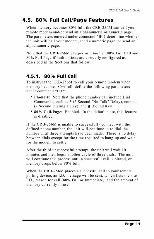
4.5. 80% Full Call/Page Features
When memory becomes 80% full, the CRB-256M can call your
remote modem and/or send an alphanumeric or numeric page.
The parameters entered under command ^B02 determine whether
the unit will call your modem, send a numeric page, or send an
alphanumeric page.
Note that the CRB-256M can perform both an 80% Full Call and
80% Full Page if both options are correctly configured as
described in the Sections that follow.
4.5.1. 80% Full CallTo instruct the CRB-256M to call your remote modem when
memory becomes 80% full, define the following parameters
under command ^B02:
� Phone #: Note that the phone number can include Dial
Commands, such as @ (5 Second "No-Talk" Delay), comma
(2 Second Dialing Delay), and # (Pound Key).
� 80% Call/Page: Enabled. In the default state, this feature
is disabled.
If the CRB-256M is unable to successfully connect with the
defined phone number, the unit will continue to re-dial the
number until three attempts have been made. There is no delay
between dials except for the time required to hang-up and wait
for the modem to settle.
After the third unsuccessful attempt, the unit will wait 10
minutes and then begin another cycle of three dials. The unit
will continue this process until a successful call is placed, or
memory drops below 80% full.
When the CRB-256M places a successful call to your remote
polling device, an I.D. message will be sent, which lists the site
I.D., reason for call (80% Full or Immediate), and the amount of
memory currently in use.
Page 11
CRB-256M User’s Guide

4.5.2. 80% Full PageIn addition to the 80% Full Call, the CRB-256M can also send
either a numeric or alphanumeric page when memory becomes
80% full.
4.5.2.1. Numeric Pagers
In order for the CRB-256M to call a numeric pager when
memory becomes 80% full, the following parameters must be
defined under command ^B02:
� Pager #: Note that the pager number can also include Dial
Commands, such as @ (5 Sec. "No-Talk" delay), comma (2
Sec. Dialing Delay), and # (Pound Key).
� 80% Call/Page: Enabled. In the default state, this feature
is disabled.
Note: In order to perform a numeric page, the
Pager ID#: field must be left blank. If the Pager
ID#: field is defined, the unit will attempt to
perform an alphanumeric page.
If your numeric paging service requires an I.D. Code to identify
the pager and/or location, this is defined under the Pager #:
prompt as shown in the example below:
<Pager Number>@<ID Code>#
For example, to send an 80% Full Page to "555-1212" with the
I.D. Code "111", the Pager #: field would contain the
following:
5551212@111#
When an 80% Full Page is sent to a numeric pager, the CRB-
256M will dial the pager once every ten minutes until memory
drops below 80% full.
Page 12
CRB-256M User’s Guide

4.5.2.2. Alphanumeric Pagers
In order for the CRB-256M to call an alphanumeric pager when
memory becomes 80% full, the following parameters must be
defined under command ^B02:
� Pager #: Note that the pager number can include Dial
Commands, such as @ (5 Sec. "No-Talk" Delay), comma (2
Sec. Dialing Delay), and # (Pound Key).
� Pager ID #: The I.D. number for your alphanumeric pager.
� 80% Call/Page: Enabled. In the default state, this feature
is disabled.
If the CRB-256M is unable to successfully connect with the
defined pager number, the unit will continue to re-dial the
number until three attempts have been made. There is no delay
between dials except to the time required to hang-up and wait for
the modem to settle.
After the third unsuccessful attempt, the unit will wait 10
minutes and then begin another cycle of three dials. The unit
will continue this process until a successful page is completed, or
memory drops below 80% full.
When the CRB-256M reaches your alphanumeric pager, the unit
will send the message "Site 000 is 80 Percent Full",
where 000 is the currently defined Site I.D..
Page 13
CRB-256M User’s Guide

5. Command Summary
Note:
� All CRB-256M commands begin with the "^B"
character. To create the "^B" character, press both
the [Ctrl] key and the [B] key simultaneously.
� To temporarily suppress the echo for any CRB-
256M command, enter a ^A character in place of
the ^B character (e.g. ^A 01 instead of ^B01).
^B00 Clear All Memory
Clears all call record data from memory. Does not clear user-
defined parameters. Before executing this command, the CRB-
256M will display a "Sure?" prompt. Type Y to proceed or N to
abort the command, and then press [Enter].
^B01 Default Parameters
Sets all parameters to factory defaults. PBX Port Baud Rate and
Modem Baud Rate will be set as specified by the SetUp
Switches. Does not effect stored call record data. Before
executing this command, the CRB-256M will display a "Sure?"
prompt. Type Y to proceed or N to abort the command, and then
press [Enter].
^B02 Set Parameters
Defines system parameters as described in Section 4.3. The
CRB-256M will display a series of prompts that allow the user to
define the password, pager number and other parameters. If an
inappropriate value is entered for any prompt, the CRB-256M
will respond with the "INVALID ARGUMENT" message.
^B03 Display Status
Displays the Status Screen as shown in Figure 3.
^B04 Download Parameters
Downloads parameter settings in a command string format,
which can be stored in an ASCII file and later uploaded to re-
configure the unit.
Page 14
CRB-256M User’s Guide

^B05 Read Data
Releases stored call data as described in Section 4.4. After data
has been released, it will be automatically cleared from the CRB-
256M's memory. Command ^B05 offers the following options:
� ^B05,R [Enter] — Data sent in ASCII format, one record
at a time. XON required to release each record.
� ^B05,C [Enter] — Data sent in ASCII format in
continuous mode. XON/XOFF used for flow control.
� ^B05,Z [Enter] — Data sent using ZModem protocol.
^B06 Display Help Menu
Displays a screen which lists all CRB-256M commands as shown
in Figure 2.
^B07 Set Immediate Callback
Instructs the unit to call back immediately after hang up. Note
that the Immediate Callback phone number is entered
independently, and may differ from the 80% Full Call/Page
numbers. To set an immediate Callback, type ^B07 [Enter].
The unit will prompt the user to enter the Immediate Callback
number. Key in the desired phone number and then press
[Enter].
Note:
� If the ^B07 command is invoked more than once
during a given session, the CRB-256M will use the
last number entered.
� After disconnect, the unit will dial the Immediate
Callback Number three times, delaying only long
enough to reset the modem between attempts. If
all three attempts are unsuccessful, the Immediate
Callback is canceled.
Page 15
CRB-256M User’s Guide

^B08 Send Test Pattern
Sends a test pattern out the Modem (Phone Line) Port. To abort
the test pattern, press [Esc] at any time. The test pattern can be
sent as a continuous stream, or sent one line at a time as
described below:
� Single Line: Type ^B08,R [Enter]. XON required to
release each record.
� Continuous Stream: Type ^B08,C [Enter]. XON/XOFF
used for flow control.
^B09 Disconnect / Hang Up
Exits from command mode and disconnects (hangs up) the
modem.
^B10 Pager Test
Performs an Alphanumeric or Numeric Pager test, depending on
the values entered at the Phone #:, Pager #:, and Pager
ID#: prompts as described in Section 4.5. After command ^B10
is invoked, the user must disconnect (hang-up) in order for the
pager test to be performed. To cancel a pager test, simply invoke
command ^B10 again prior to hanging up.
Page 16
CRB-256M User’s Guide

6. RS-232 Interface
Pin Signal I/O
2 TXD Out
3 RXD Input
4 RTS Out
7 GND —
20 DTR Out
(All other pins are open)
7. Specifications
Interface:
PBX Port: RS-232, DB-25 Male, DTE, 7 or 8 bits
(selectable).
Phone Line: RJ11 Jack, 8 bits, No parity, fixed.
Data Rate: (Dip Switch Selectable)
PBX Port: 300, 1200, 2400, 9600 bps
Modem: 1200, 2400 bps
Memory: 256K Static RAM, Battery Backed.
Battery: Three Year Life
Size: 2.20" x 4.50" x 6.00" (H x W x D)
Weight: 1 lb.
Power: AC Adapter, 9 VDC @ 300 ma
Temperature: 50�F to 104�F (10�C to 40�C) Operating
Humidity: 20% to 80% Relative Humidity
Page 17
CRB-256M User’s Guide
Figure 4: RS-232 Interface (PBX Port)
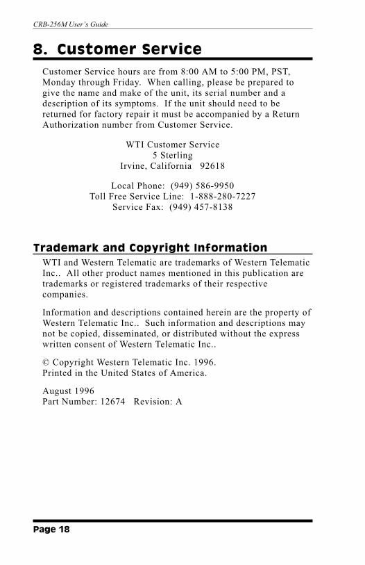
8. Customer Service
Customer Service hours are from 8:00 AM to 5:00 PM, PST,
Monday through Friday. When calling, please be prepared to
give the name and make of the unit, its serial number and a
description of its symptoms. If the unit should need to be
returned for factory repair it must be accompanied by a Return
Authorization number from Customer Service.
WTI Customer Service
5 Sterling
Irvine, California 92618
Local Phone: (949) 586-9950
Toll Free Service Line: 1-888-280-7227
Service Fax: (949) 457-8138
Trademark and Copyright InformationWTI and Western Telematic are trademarks of Western Telematic
Inc.. All other product names mentioned in this publication are
trademarks or registered trademarks of their respective
companies.
Information and descriptions contained herein are the property of
Western Telematic Inc.. Such information and descriptions may
not be copied, disseminated, or distributed without the express
written consent of Western Telematic Inc..
© Copyright Western Telematic Inc. 1996.
Printed in the United States of America.
August 1996
Part Number: 12674 Revision: A
Page 18
CRB-256M User’s Guide


5 Sterling � Irvine � California 92618-2517(949) 586-9950 � Toll Free: 1-800-854-7226Fax: (949) 583-9514 � http://www.wti.com