calibration methodology for the ... - earth online - esa · calibration methodology for the...
TRANSCRIPT

Calibration Methodology for the Airborne DispersivePushbroom Imaging Spectrometer (APEX)
Jens Nieke, Johannes W. Kaiser, Daniel Schläpfer, Jason Brazile, Klaus I. Itten(RSL),
Horst Schwarzer, Peter Strobl (DLR),Michael E. Schaepman (WUR),
Gerd Ulbrich (ESA)
and the APEX team
Recent publications:Recent publications:
UlbrichUlbrich,, Meynart Meynart,, Nieke Nieke, and the APEX team, SPIE, and the APEX team, SPIE Vol Vol. 5570 (2004). 5570 (2004)
NiekeNieke, Kaiser,, Kaiser, Schlaefer Schlaefer,, Brazile Brazile,, Itten Itten, , Strob lStrob l,, Schaepman Schaepman, , UlbrichUlbrich, and the APEX team, SPIE, and the APEX team, SPIE Vol Vol. 5570 (2004). 5570 (2004)

Outline of the Talk
• APEX Project Background• APEX Calibration Specifications (summary)• APEX Calibration Tools
• In-flight Characterization facility IFC• Calibration Homebase CHB• Vicarious and cross calibration• PAF (assimilation scheme)
• Conclusion

Scientific GoalsScientific requirements for APEX have been derived using a performance model forat sensor radiance*.Goal: Development of advanced methods for bio-geophysical parameter retrieval for
• Vegetation,• Soils, rocks & minerals,• Snow and Ice,• Atmosphere,• Coastal and inland waters analysis
and cross calibration with spaceborne EO systems
* Schläpfer & Schaepman,Appl. Optics 41(27), 2002

Hyperspectral Applications
100.0%
0.0%
Precision Farming
Ecology Modeling
Forest Fire Modeling
Water QualityAir Pollution
Natural Hazards

APEX Organization

APEX Selected Calibration Specifications
• Total FOV 28˚ deg, IFOV 0.49 mrad (spatial resolution across slit)
• Total of across-track pixels: 1000 for both detectors
• Total spectral pixels on chip, prior to binning 312 (VNIR) & 199 (SWIR), may beread out for calibration purpose simultaneously
• Total spectral bands in operational mode ~ 300 programmable channels resultingin a spectral sampling interval (and width) of Δλ ≤ 5 nm in VNIR (400 - 1050 nm) andΔλ ≤ 10 nm in SWIR (1050 - 2500 nm)
• Instrument temporal radiometric uncertainty within a flight section: better 0.02• Radiometric performance accuracy: instrument shall allow absolute
calibration accuracy up to 0.03• Interval for instrument re-calibration: after a complete flight season• Center wavelength accuracy: < 0.2 nm

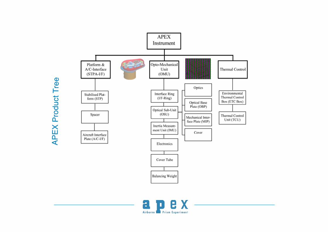
Schematic APEX Instrument Components
APEX
Pro
duct
Tre
eAP
EX P
rodu
ct T
ree

Instrument Set-upInstrument Set-up

Instrument ConfigurationInstrument Configuration
Environmental ThermalControl Box – (ETC)
Stabilizing Platform -STP
ThermalControl Unit
Aircraft I/F
Spectrometer(OMU)

Instrument Set-up in AircraftInstrument Set-up in Aircraft
APEX Instrumentwith Stabilizing Platform integrated inEnvironmental Thermal Control Box
Aircraft I/F
Control and StorageUnit
Power DistributionUnit
Navigation SubSystem
Operator
Monitor
Flight ManagementSystem

APEX Hyperspectral ImagerAPEX Hyperspectral Imager
• Sealed spectrometercompartment
• Thermal stabilized duringoperation: Better 2 ºC, gradientless 0.5 ºC
• Max. deformation of OpticalBase Plate (OBP) less 0.040mm due to air pressurevariations
• Co-registration error VNIR-to-SWIR channels about 0.5 pixel
• Overall mass: 72 kg, withoutcounterweight for COGadjustment
804 mmFits into PAV-30 Stabilizing Platform,Opening diameter 443 mm

Spectrometer - Design ConceptSpectrometer - Design Concept

Type CCD 55-30 from E2V Technologies (GB)
• Frame transfer mode,• 1252 x 1152 p ixel (used 1000 x 393)• Pixel p itch 22.5 x 22.5 µm2, fill factor 100%• Back illuminated• Operated in non-inverted mode• Read out frequency 7 Mpix/s• Operated in dither clocking
mode without cooling• integration time independent
from frame transfer time
VNIR- DetectorVNIR- Detector
0
20
40
60
80
100
380 400 500 650 750 900 1000
Wavelength [nm]Q
ua
ntu
m E
ffic
ien
cy
[%]

SWIR DetectorSWIR Detector
HgCdTe detector array - hybridized on CMOS multiplexer1000 x 256 square pixel, 30 micron, addressable readout, fast operationIntegrated in cryostat cooler assemblyWL range: 0.94 – 2.50 micronQE: > 55 % averageTop.: 130 – 165 K
Dewar
Cooler
Focal Plane Assembly BB
Sapphire Window
Transfer Line
Pre-EM Detector with Cryostat/Dewar Assembly
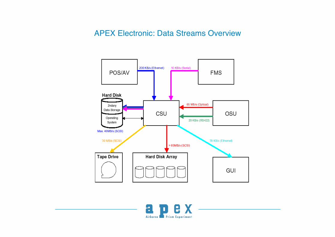
APEX Electronic: Data Streams Overview

APEX PAF: The Processor FoundationPAF Hardware: Linux,PAF Hardware: Linux,
Archiving SystemArchiving SystemPAF: IDL-PAF: IDL-emacsemacs, XML-tools,, XML-tools,
CVS, TCL/CVS, TCL/webshwebsh
PAF Processor: PAF Processor: IDL, XML, CIDL, XML, C
APEX PAF
SearchAPEX
Archive
Server
Core
Web
Processor
Input
ToolsProcessing
ToolsCollaboration
ToolsBrowsing
Docs
Co-Developers
Users
Operators
CHB Data

APEX higher processing Level 1B, 1C, 2, 3
Atmosph. AuxilaryData
Image Attribute
Data
Quality Description
ParametricOrthorecti-
fication(PARGE)
AtmosphericTopographicCorrection(ATCOR)
Geometry Index
AtmosphericTopographic
Corrected Cube
CubeGeocoding
Geocoded,HDRF Cube
DEM
Calibrated Uniform
Image DataCube
Calibrated Position
and Attitude Custom products
ProductGeneration
Product Description
Level 1B Level 1C Level 2CLevel 2A Level 2B
Bad Pixel Map
Rectification(PARGE)
Rectified Uniform Cube Atmospheric
Normalization
Geometry Index
ApparentReflectance
Cube
Level 3A Level 3B
Standard products
Product Description
Research products
Product Description
Level 3C

APEX Calibration Methodology
APEX Calibration Tools:
• In-flight Characterization facility IFC• Calibration Homebase CHB• Vicarious and cross calibration• PAF (assimilation scheme)

Opto/Mechanical Unit (spectrometer hermetic sealed) with IFC*
Optical Baseplate(actively cooled)
* In-Flight/on-board Characterisation facility
QTH-Lamp, stabilized
Connectors
Baffle

In-Flight/on-board Characterisation Facility - IFC
Baffle
Optical Beampath
Stabilized QTH-lamp
Filter wheel

APEX Spectral Calibration VNIR (312 bands prior binning)

APEX Spectral Calibration SWIR (199 bands)

Calibration Home Base
The CHB will be established at DLR,Oberpfaffenhofen (D) for regular instrument re-calibration during APEX exploitation phase
For laboratory calibration a number ofenvironmental prerequisites are met:
•• Foundation built as seismic blockFoundation built as seismic block•• accessible by large trolleys (no stairs, stepsaccessible by large trolleys (no stairs, steps
or elevators)or elevators)•• close to airfieldclose to airfield•• large enough to host equipment, high ceilinglarge enough to host equipment, high ceiling
and craneand crane•• semi-clean environmentsemi-clean environment•• dark room facilitiesdark room facilities•• heated and temperature controlledheated and temperature controlled•• low humiditylow humiditySeismic block
7 m
6 m12 m

Calibration Home Base
APEX-instrument
Rotary stage withfolding mirror,mounted on linearstage
Mirror-Collimatorsfor spectral andspatial calibration(not shown)Optical bench (granite)

APEX Instrument – Radiometric Calibration
ADS
Integrating
Sphere
Field Spectrometer with Fiber Optics
FOV
QTH Lamps for various radiance levels
APEX
Ø1,60 m
Principle of the radiometriccalibration of APEX instrumentwith DLR’s large integratingsphere

Vicarious and Cross-Calibration
Block diagram for theBlock diagram for theradiance-basedradiance-basedcalval calval method tomethod tocompare TOAcompare TOAradiance predictedradiance predictedfrom APEXfrom APEXmeasurementsmeasurements(TOA radiance 2,3)(TOA radiance 2,3)with those measuredwith those measuredby the spaceborneby the spacebornesensorsensor((TOAradiance TOAradiance 1).1).Hsite Hsite is the altitude ofis the altitude ofthe site, HAPEX isthe site, HAPEX isthe flight altitude ofthe flight altitude ofAPEX and theAPEX and theHTOA the top HTOA the top ofof--atmosphere altitude.atmosphere altitude.

APEX 312 Bands prior binning

APEX Cross-Calibration Capabilities

Calibration Parameter Definition
aiθcentre across-track angleθj,k
aiλcentre wavelengthλj,k
bad/dead pixel mapdj,k
dark current factordcj,k
gain factorGj,k
Parameterised byDescriptionSymbol
for each pixelfor each pixel for all pixels for all pixels
!
b =
Gj ,k
dcj ,k
ai"
ai#
$
%
& &
'
& &
(
)
& &
*
& &
vector of coefficients + their covariance matrix vector of coefficients + their covariance matrix SS

Calibration Coefficient Calculation
Sources of Information: heterogeneous calibration measurements system insight
Goal: combine all information in an optimal way
Solution: data assimilation
• optimal combination according to covariances• accounts for temporal evolution• system insight quantified (correlations) requires covariance matrix
quantitative description with b, Ssystem model for b and Scorrelations in Sparameterizations for b

Example: 1-d Kalman Filter

APEX PAF: The Processor Foundation
PAF Hardware: Linux,PAF Hardware: Linux,Archiving SystemArchiving System
PAF: IDL-PAF: IDL-emacsemacs, XML-tools,, XML-tools,CVS, TCL/CVS, TCL/webshwebsh
PAF Processor: PAF Processor: IDL, XML, CIDL, XML, C
APEX PAF
SearchAPEX
Archive
Server
Core
Web
Processor
Input
ToolsProcessing
ToolsCollaboration
ToolsBrowsing
Docs
Co-Developers
Users
Operators
CHB Data

Calibrated DataCalibration Parameters
Quality Reports
Data Download:- Segregation- Synchronization- Bad Pixel Detection
RawInstrument
Data
Applanix INS Data
Sensor AttributeData
CalibrationProcessor
Position and AttitudeTransformation
Data Calibration:- Electronic smear,- Radiometric response,- Bad p ixels,- Optical effects
VicariousCalibration Data
ConsistencyCheck
Laboratory Calibration
Parameter Files
Archived Instrument Data,
Quicklooks
TrackAir FMS Data
Raw Data Level 1BLevel 0B
LaboratoryCalibration Data
IFC Calibration Parameter Files
Vicarious Calibration
Vicarious CalibrationParameter Files
Independent VicariousQuality Report
Assimilation Processor
Vicarious Validation

Conclusions
APEX timeline is currently before the Critical Design Review (CDR) close-outmeeting
the PAF version 0.3 has been released in Aug. 2004 design and breadboard activities of the In-Flight Calibration facility IFC werefinalized bread boarding phase of the Calibration Home Base CHB is ongoing.
First data for the scientific user community shall be available in 2006!
We are proposing the APEX instrument as a cross-calibration tool to thescience community!

Last but not least…
www.apex-esa.org