calculator netafim
TRANSCRIPT

GLOSSARY Flow Rate Variation - The difference in percentage between the maximum emitter’s discharge to the minimum emitter’s discharge. Emission uniformity Flow rate Inlet lateral flow rate Emitter flow rate Irrigation rate Kv Kd Exponent Inside diameter Nominal diameter Inlet Velocity Friction factor Friction factor Water peak demand Daily irrigation time Flushing system Pressure Head pressure End pressure Pressure rating

SETTING The Settings window helps set the program language setting and determine whether to use the Metric or the US measuring system. Selecting the interface language: In the Setting window select the Languages tab. From the drop-down list select a language then press the “GO” button. Restart the program for changes to take affect. Selecting the measuring system: In the Setting window select the System tab. Chose either Metric or US system then press the “GO” button. Restart the program for changes to take affect.
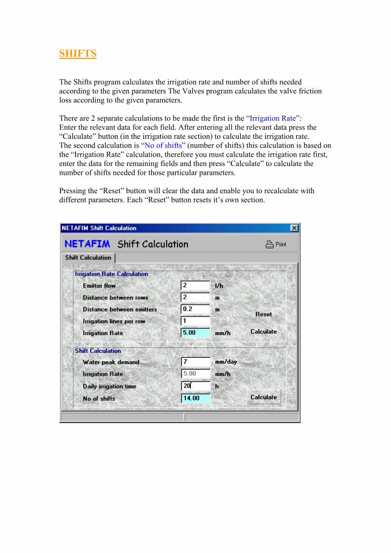
SHIFTS The Shifts program calculates the irrigation rate and number of shifts needed according to the given parameters The Valves program calculates the valve friction loss according to the given parameters. There are 2 separate calculations to be made the first is the “Irrigation Rate”: Enter the relevant data for each field. After entering all the relevant data press the “Calculate” button (in the irrigation rate section) to calculate the irrigation rate. The second calculation is “No of shifts” (number of shifts) this calculation is based on the “Irrigation Rate” calculation, therefore you must calculate the irrigation rate first, enter the data for the remaining fields and then press “Calculate” to calculate the number of shifts needed for those particular parameters. Pressing the “Reset” button will clear the data and enable you to recalculate with different parameters. Each “Reset” button resets it’s own section.

VALVES The Valves program calculates the valve friction loss according to the given parameters. In order to calculate the valves friction loss the following parameters should be entered: Valve type
Select the type from the list. The basic Valves database consists of: Aquanet, TNL and PRV valve types, but you can add/delete/change valves type and related data and parameters using the “DB Update” program.
Configuration Select the desired configuration. Configuration options vary according to valve type selection.
Diameter Select the desired valve diameter. Selecting the diameter automatically sets the “Kv” field value.
Flow Rate Enter the desired flow rate.
After entering all the relevant data press the “Calculate” button to calculate the friction loss. Pressing the “Reset” button will clear the data and enable you to recalculate with different parameters.
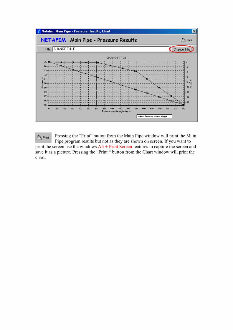
Pressing the “Print” button from the Main Pipe window will print the Main Pipe program results but not as they are shown on screen. If you want to
print the screen use the windows Alt + Print Screen features to capture the screen and save it as a picture. Pressing the “Print “ button from the Chart window will print the chart.
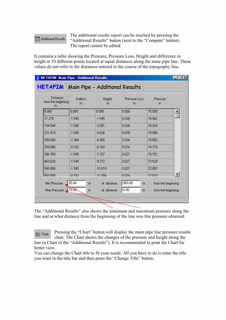
The additional results report can be reached by pressing the “Additional Results” button (next to the “Compute” button). The report cannot be edited.
It contains a table showing the Pressure, Pressure Loss, Height and difference in height at 10 different points located at equal distances along the mine pipe line. These values do not refer to the distances entered in the course of the topography line.
The “Additional Results” also shows the minimum and maximum pressure along the line and at what distance from the beginning of the line was this pressure obtained.
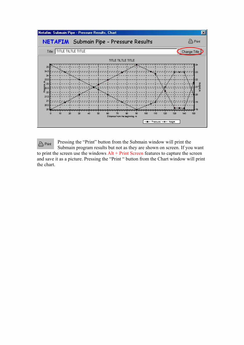
Pressing the “Chart” button will display the main pipe line pressure results chart. The Chart shows the changes of the pressure and height along the
line (a Chart of the “Additional Results”). It is recommended to print the Chart for better view. You can change the Chart title to fit your needs. All you have to do is enter the title you want in the title bar and then press the “Change Title” button.
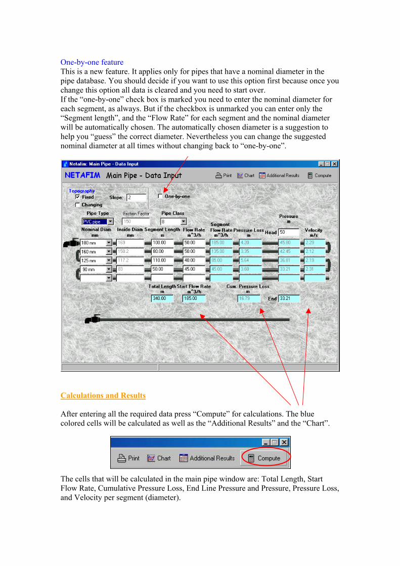
One-by-one feature This is a new feature. It applies only for pipes that have a nominal diameter in the pipe database. You should decide if you want to use this option first because once you change this option all data is cleared and you need to start over. If the “one-by-one” check box is marked you need to enter the nominal diameter for each segment, as always. But if the checkbox is unmarked you can enter only the “Segment length”, and the “Flow Rate” for each segment and the nominal diameter will be automatically chosen. The automatically chosen diameter is a suggestion to help you “guess” the correct diameter. Nevertheless you can change the suggested nominal diameter at all times without changing back to “one-by-one”.
Calculations and Results After entering all the required data press “Compute” for calculations. The blue colored cells will be calculated as well as the “Additional Results” and the “Chart”. The cells that will be calculated in the main pipe window are: Total Length, Start Flow Rate, Cumulative Pressure Loss, End Line Pressure and Pressure, Pressure Loss, and Velocity per segment (diameter).
MAIN PIPE The Main Pipe program calculates the cumulative pressure loss and the water flow velocity in the main pipe distributing water pipe (single or telescopic). It changes to suit the required irrigation system parameters. The basic pipes database consists of mainly PE, PVC and Layflat pipes, but the pipes database is very flexible. You can add/delete/change pipes type, class, nominal and inside diameters using the “DB Update” program. In order to design the main pipe line the following parameters should be entered. First you should decide if you want to work with “one-by-one” option or without. Then select the “Pipe Type” and only after that fill the rest of the parameters. Pipe Type
Select the desired pipe type from a list: PE pipe , PVC pipe, Layflat, Aluminum, and other pipes, depending on the pipe database.
Friction Factor For PE PVC and LAYFLAT pipes a friction factor of 150 (based on Darcy-Wiesbach equation) is automatically set. For other pipes the appropriate friction factor must be entered. The friction factor value ranges between 50 to 200 , in case of an improper entry of friction factor, a warning is displayed.
Pipe Class Select the suited pipe class from the list. The list changes according to the “Pipe Type” selection. Some pipes don’t have a class either because there is no such thing for that type of pipe or because it wasn’t filled in the database. Either way if the list is blank, ignore the field (pipe class normally represents the maximum allowed working pressure in PSI units).
Head Pressure Enter the required pressure at the beginning of the main pipe line.
Topography The same idea as in emitters only for main pipe line.
Nominal Diam (Nominal Diameter) Select the nominal diameter from the list. The list changes according to your “Pipe Type” selection. In most cases selecting the Nominal Diameter automatically enters the value for “Inside Diameter” field. If the list is blank ignore the field and enter the “Inside Diameter” value instead.
Inside Diam (Inside Diameter) This field is automatically set for pipes that are in the database. In the case it isn’t set automatically you should enter it manually, remember the value should be the INSIDE diameter.
Segment Length Enter the required main pipe segment length.
Flow Rate Enter the required flow rate for the segment.
You can build a telescopic pipe up to 5 different diameters. The upper field is always larger then the one below, therefore always start with the largest diameter and gradually advance to the smallest diameter. You cannot select a second diameter before you enter a value in the “Segment Length” field.
Pressing the “Print” button from the Submain window will print the Submain program results but not as they are shown on screen. If you want
to print the screen use the windows Alt + Print Screen features to capture the screen and save it as a picture. Pressing the “Print “ button from the Chart window will print the chart.

The additional results report can be reached by pressing the “Additional Results” button (next to the “Compute” button). The report cannot be edited.
It contains a table showing the Pressure, Pressure Loss, Height and difference in height at 10 different points located at equal distances along the line. These values do not refer to the distances entered in the course of the topography line.
The “Additional Results” also shows the minimum and maximum pressure along the line and at what distance from the beginning of the line was this pressure obtained.
Pressing the “Chart” button will display the submain pipe line pressure results chart. The Chart shows the changes of the pressure and height
along the line (a Chart of the “Additional Results”). It is recommended to print the Chart for better view. You can change the Chart title to fit your needs. All you have to do is enter the title you want in the title bar and then press the “Change Title” button.
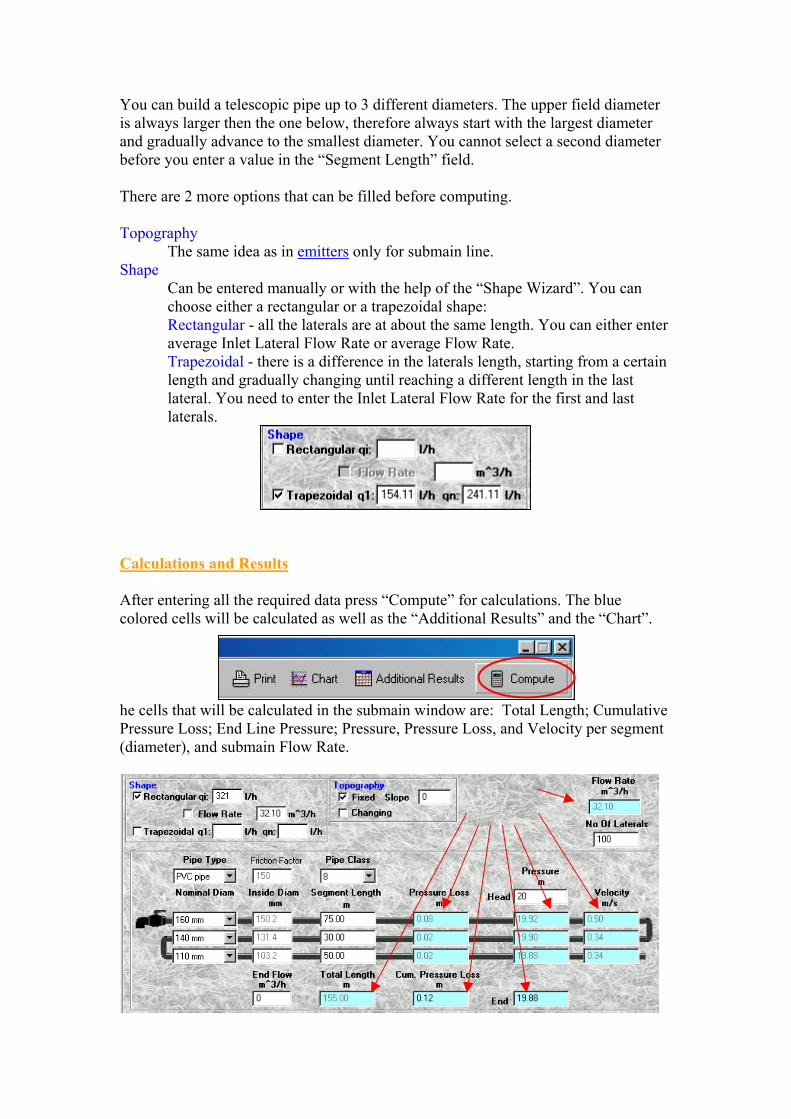
You can build a telescopic pipe up to 3 different diameters. The upper field diameter is always larger then the one below, therefore always start with the largest diameter and gradually advance to the smallest diameter. You cannot select a second diameter before you enter a value in the “Segment Length” field. There are 2 more options that can be filled before computing. Topography
The same idea as in emitters only for submain line. Shape
Can be entered manually or with the help of the “Shape Wizard”. You can choose either a rectangular or a trapezoidal shape: Rectangular - all the laterals are at about the same length. You can either enter average Inlet Lateral Flow Rate or average Flow Rate. Trapezoidal - there is a difference in the laterals length, starting from a certain length and gradually changing until reaching a different length in the last lateral. You need to enter the Inlet Lateral Flow Rate for the first and last laterals.
Calculations and Results After entering all the required data press “Compute” for calculations. The blue colored cells will be calculated as well as the “Additional Results” and the “Chart”. he cells that will be calculated in the submain window are: Total Length; Cumulative Pressure Loss; End Line Pressure; Pressure, Pressure Loss, and Velocity per segment (diameter), and submain Flow Rate.
SUBMAIN The SubMain program calculates the cumulative pressure loss and the water flow velocity in the submain distributing water pipe (single or telescopic). It changes to suit the required irrigation system parameters. The basic pipes database consists of mainly PE, PVC and Layflat pipes, but the pipes database is very flexible. You can add/delete/change pipes type, class, nominal and inside diameters using the “DB Update” program. In order to design the submain line the following parameters should be entered. You should select the “Pipe Type” first and only after that fill the rest of the parameters. Pipe Type
Select the desired pipe type from a list: PE pipe, PVC pipe, Layflat, Aluminum, and other pipes, depending on the pipe database.
Friction Factor For PE PVC and LAYFLAT pipes a friction factor of 150 (based on Darcy-Wiesbach equation) is automatically set. For other pipes the appropriate friction factor must be entered. The friction factor value ranges between 50 to 200 , in case of an improper entry of friction factor, a warning is displayed.
Pipe Class Select the suited pipe class from the list. The list changes according to the “Pipe Type” you selected. Some pipes don’t have a class either because there is no such thing for that type of pipe or because it wasn’t filled in the database. Either way if the list is blank ignore the field (pipe class normally represents the maximum allowed working pressure in BAR units).
Head Pressure Enter the required pressure at the beginning of the submain line.
End Flow Enter the flow rate at the end of the submain line. The common value for this field is 0.
No Of Laterals (Number of Laterals) Enter the number of laterals along the entire distribution pipe, no matter whether it is a single diameter or a pipe composed of a number of diameters (“telescopic” pipe).
Nominal Diam (Nominal Diameter) Select the nominal diameter from the list. The list changes according to your “Pipe Type” selection. In most cases selecting the Nominal Diameter automatically enters the value for “Inside Diameter” field. If the list is blank ignore the field and enter the “Inside Diameter” value instead.
Inside Diam (Inside Diameter) This field is automatically set for pipes that are in the database. In the case it isn’t set automatically you should enter it manually, remember the value should be the INSIDE diameter.
Segment Length Enter the required submain segment length.
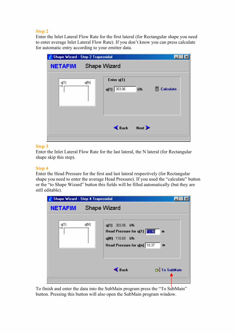
Step 2 Enter the Inlet Lateral Flow Rate for the first lateral (for Rectangular shape you need to enter average Inlet Lateral Flow Rate). If you don’t know you can press calculate for automatic entry according to your emitter data. Step 3 Enter the Inlet Lateral Flow Rate for the last lateral, the N lateral (for Rectangular shape skip this step). Step 4 Enter the Head Pressure for the first and last lateral respectively (for Rectangular shape you need to enter the average Head Pressure). If you used the “calculate” button or the “to Shape Wizard” button this fields will be filled automatically (but they are still editable). To finish and enter the data into the SubMain program press the “To SubMain” button. Pressing this button will also open the SubMain program window.
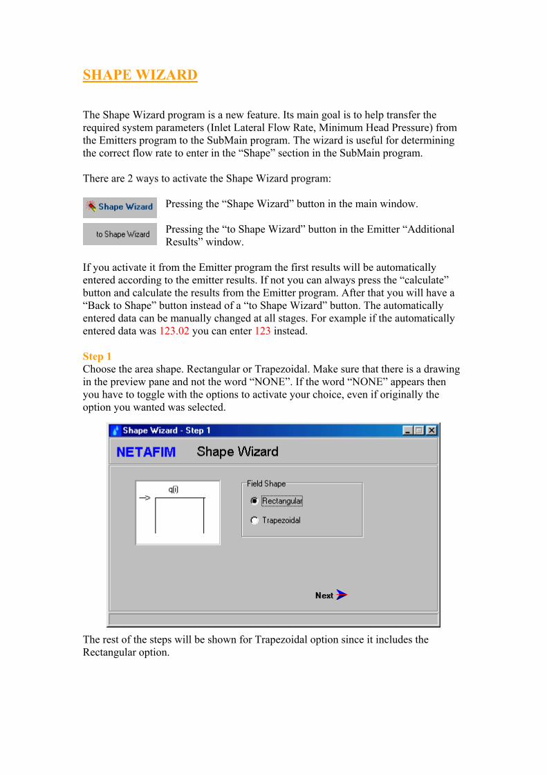
SHAPE WIZARD The Shape Wizard program is a new feature. Its main goal is to help transfer the required system parameters (Inlet Lateral Flow Rate, Minimum Head Pressure) from the Emitters program to the SubMain program. The wizard is useful for determining the correct flow rate to enter in the “Shape” section in the SubMain program. There are 2 ways to activate the Shape Wizard program:
Pressing the “Shape Wizard” button in the main window. Pressing the “to Shape Wizard” button in the Emitter “Additional Results” window.
If you activate it from the Emitter program the first results will be automatically entered according to the emitter results. If not you can always press the “calculate” button and calculate the results from the Emitter program. After that you will have a “Back to Shape” button instead of a “to Shape Wizard” button. The automatically entered data can be manually changed at all stages. For example if the automatically entered data was 123.02 you can enter 123 instead. Step 1 Choose the area shape. Rectangular or Trapezoidal. Make sure that there is a drawing in the preview pane and not the word “NONE”. If the word “NONE” appears then you have to toggle with the options to activate your choice, even if originally the option you wanted was selected.
The rest of the steps will be shown for Trapezoidal option since it includes the Rectangular option.

Pressing the “Print” button from the Emitter window will print the Emitter program results but not as they are shown on screen. If you want to print
the screen use the windows Alt + Print Screen features to capture the screen and save it as a picture. Pressing the “Print “ button from the Chart window will print the chart. Note: If the maximal pressure in one of the non-regulated emitters in the line is lower than 0.1 m or higher than 50 m, the calculations will be stopped on this emitter (even if the calculation is still incomplete). The emitter calculation results will be presented along with an appropriate warning displayed in red. For example: WARNING – Inlet pressure is above 50 m ! For a regulated emitter the calculation will be performed as described above. However, if the minimum pressure in one of the emitters in the line is lower than 5 m, an appropriate warning will be displayed in red. For example: WARNING – Minimum pressure is Below 5 m !
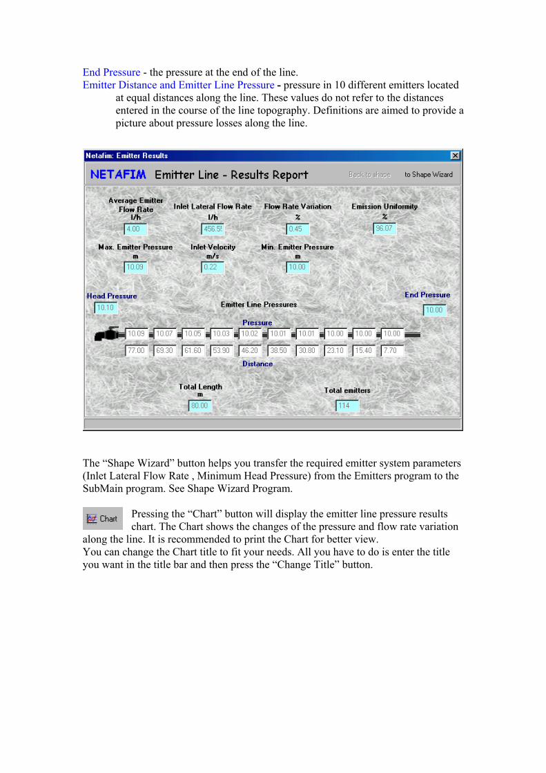
End Pressure - the pressure at the end of the line. Emitter Distance and Emitter Line Pressure - pressure in 10 different emitters located
at equal distances along the line. These values do not refer to the distances entered in the course of the line topography. Definitions are aimed to provide a picture about pressure losses along the line.
The “Shape Wizard” button helps you transfer the required emitter system parameters (Inlet Lateral Flow Rate , Minimum Head Pressure) from the Emitters program to the SubMain program. See Shape Wizard Program.
Pressing the “Chart” button will display the emitter line pressure results chart. The Chart shows the changes of the pressure and flow rate variation
along the line. It is recommended to print the Chart for better view. You can change the Chart title to fit your needs. All you have to do is enter the title you want in the title bar and then press the “Change Title” button.

You don’t have to fill all 10 pairs but your last distance value has to be higher or equal to total pipe length. The easiest way to go between the cells is using the “TAB” key. Calculations and Results After entering all the required data press “Compute” for calculations. The blue colored cells will be calculated as well as the “Additional Results” and the “Chart”. The cells that will be calculated in the emitter window are : Total Emitters, Total Length, Total Pressure Loss; Pressure Loss, Head Pressure, and Velocity per segment; and Segment Length when using any Calculation method that is not “Emitter Line Length”.
The additional results report can be reached by pressing the “Additional Results” button (next to the “Compute” button). The report cannot be edited.
It contains the following results: Average Emitter Flow Rate - calculated as the result of dividing “Inlet Lateral Flow
Rate” by “Total Emitter Quantity”. Inlet Lateral Flow Rate - the cumulative flow rate along the entire line. Flow Rate Variation - is the difference in percentage between the maximum emitter’s
discharge to the minimum emitter’s discharge. FV(%)=[(Qmax - Qmin) / Qmax]*100
Emission Uniformity - is the result of the following formula as specified by the ASAE: EU(%)=(Qmin / Qmax)*[1-1.27*CV/n1/2]
Min/Max Emitter Pressure - the pressure in the emitter with extreme (minimum or maximum) pressure (not necessarily at the beginning or the end of line).
Inlet Velocity - the maximum velocity at the lateral inlet. Total Length - the result of the computation or the given value for lateral length. Total Emitters - the cumulative number of emitters along the given length. Emitter Line pressures: Head Pressure - the pressure at the beginning of the line.
d. “Emission Uniformity”- similar to “flow rate variation”, calculation will be executed to achieve the desired emission uniformity, and will generate the maximum lateral length under these conditions. Therefore there is no need to fill the “Segment Length” field (8). Emission uniformity units are also % but the common value for this field is any value above 85 %. This option is available for non PC emitters only.
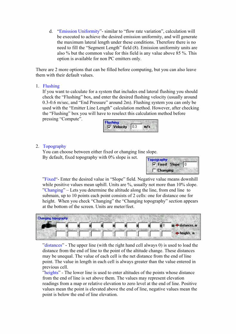
There are 2 more options that can be filled before computing, but you can also leave them with their default values. 1. Flushing
If you want to calculate for a system that includes end lateral flushing you should check the “Flushing” box, and enter the desired flushing velocity (usually around 0.3-0.6 m/sec, and “End Pressure” around 2m). Flushing system you can only be used with the “Emitter Line Length” calculation method. However, after checking the “Flushing” box you will have to reselect this calculation method before pressing “Compute”.
2. Topography
You can choose between either fixed or changing line slope. By default, fixed topography with 0% slope is set. ”Fixed“- Enter the desired value in “Slope” field. Negative value means downhill while positive values mean uphill. Units are %, usually not more than 10% slope. ”Changing” – Lets you determine the altitude along the line, from end line to submain, up to 10 points each point consists of 2 cells: one for distance one for height. When you check “Changing” the “Changing topography” section appears at the bottom of the screen. Units are meter/feet.
”distances” - The upper line (with the right hand cell always 0) is used to load the distance from the end of line to the point of the altitude change. These distances may be unequal. The value of each cell is the net distance from the end of line point. The value in length in each cell is always greater than the value entered in previous cell. ”heights” - The lower line is used to enter altitudes of the points whose distance from the end of line is set above them. The values may represent elevation readings from a map or relative elevation to zero level at the end of line. Positive values mean the point is elevated above the end of line, negative values mean the point is below the end of line elevation.

field you can activate the second pipe type by pressing the “TAB” key on the keyboard or moving to another field.
“Inside Diam” (inside diameter”), “KD” and “Exponent” fields are automatically set according to the emitter type and pipe parameters selected. The value of these fields cannot be changed, unless the change was made in the database.
8. Segment Length Enter the required segment length.
9. End Pressure The actual value for calculation of pressure at the furthest emitter. The common values for this field are: around 10m for drippers. around 20m for mini-sprinklers. between 20-30m for sprinklers. around 2m when using flushing system.
10. Calculation Method There are 4 calculation methods are available which are used in accordance with the loaded data:
a. “Emitter Line Length” - calculation will be executed for the entire designated length.
b. “Pressure Range”- calculation will be executed in a way that makes sure the maximal pressure variation between maximum emitter’s pressure to minimum emitter’s pressure does not exceed the pressure range you entered. The computation result will also show the maximum lateral length under the designated conditions. Therefore it is not necessary to fill the “Segment Length” field (8) if you intend to use this method. This option is available for PC (exponent value is equal to zero) emitters only. Pressure range units are meter/feet.
c. ”Flow Rate Variation” – calculation will be executed to achieve the requested flow variation and will generate the maximum lateral length under these conditions. Therefore there is no need to fill the “Segment Length” field (8). Flow variation units are %. The common values for this field are between 10-15%. This option is available for non PC emitters only (exponent value is above zero).
4 5 6
7 8
9
10
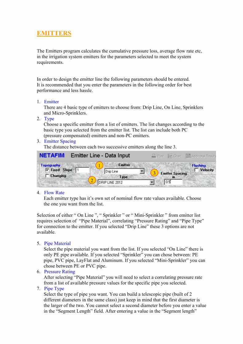
EMITTERS The Emitters program calculates the cumulative pressure loss, average flow rate etc, in the irrigation system emitters for the parameters selected to meet the system requirements. In order to design the emitter line the following parameters should be entered. It is recommended that you enter the parameters in the following order for best performance and less hassle. 1. Emitter
There are 4 basic type of emitters to choose from: Drip Line, On Line, Sprinklers and Micro-Sprinklers.
2. Type Choose a specific emitter from a list of emitters. The list changes according to the basic type you selected from the emitter list. The list can include both PC (pressure compensated) emitters and non-PC emitters.
3. Emitter Spacing The distance between each two successive emitters along the line 3.
4. Flow Rate Each emitter type has it’s own set of nominal flow rate values available. Choose the one you want from the list.
Selection of either “ On Line ”, “ Sprinkler ” or “ Mini-Sprinkler ” from emitter list requires selection of “Pipe Material”, correlating “Pressure Rating” and “Pipe Type” for connection to the emitter. If you selected “Drip Line” these 3 options are not available. 5. Pipe Material
Select the pipe material you want from the list. If you selected “On Line” there is only PE pipe available. If you selected “Sprinkler” you can chose between: PE pipe, PVC pipe, LayFlat and Aluminum. If you selected “Mini-Sprinkler” you can chose between PE or PVC pipe.
6. Pressure Rating After selecting “Pipe Material” you will need to select a correlating pressure rate from a list of available pressure values for the specific pipe you selected.
7. Pipe Type Select the type of pipe you want. You can build a telescopic pipe (built of 2 different diameters in the same class) just keep in mind that the first diameter is the larger of the two. You cannot select a second diameter before you enter a value in the “Segment Length” field. After entering a value in the “Segment length”
1
23

The database consists of pipes manufactured in compliance with the relevant local standards: P.E. pipes - normative reference 150, DIN, ISO
P.V.C pipes - normative reference 150, DIN, ISO

NOTES:
There are three types of parameters : - Selected from a list provided by the program (the arrow next to the cell is clicked to display the list). - Entered by the user in accordance with his own considerations. - Automatically inserted by the program to suit the entry made. These entries will usually have a more faded gray color, unlike the users entries black color. However, when the user’s entry creates an improper result, a warning message will appear at the bottom of the screen warning about the improper parameter result. For example: WARNING – Inlet Pressure Is Above 50 m ! Then the entry subject to a correction must be clicked and the new entry made.
If you try to compute (clicking the Compute cell) with lacking or illegal data, a request to enter the omitted value, or correct the illegal one, will be displayed. For example: After clicking the OK button the window will be closed, and the cursor jumps to the appropriate cell. Enter the required value and reinitiate the computation.
Pay attention to the measurement units! Make sure your entries are in the units designated next to each cell heading, otherwise wrong computation results will be obtained.
The print button will print to the default printer. You can not choose the printer after you pressed this button. Also notice that it doesn’t always print the screen as it is but it does print the current program results.
The “ENTER” key is inoperative in the program.
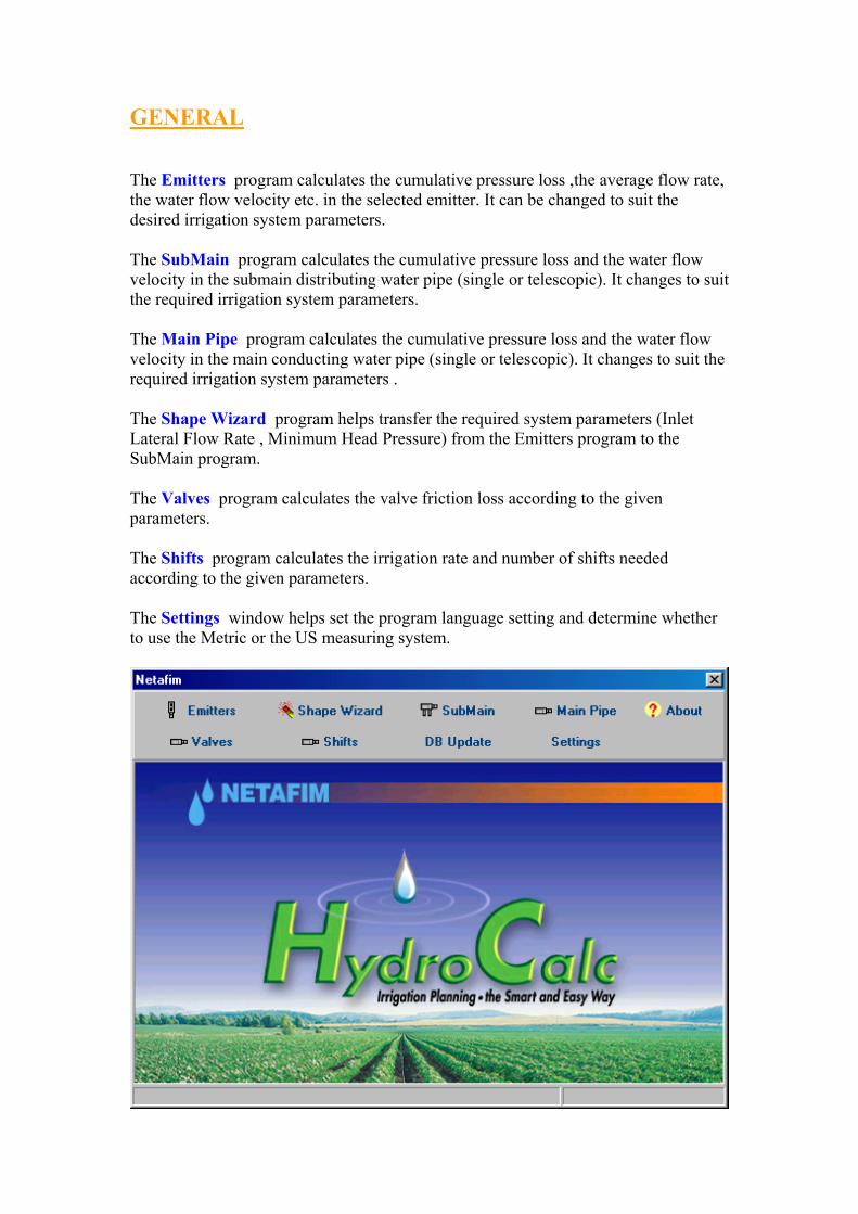
GENERAL The Emitters program calculates the cumulative pressure loss ,the average flow rate, the water flow velocity etc. in the selected emitter. It can be changed to suit the desired irrigation system parameters. The SubMain program calculates the cumulative pressure loss and the water flow velocity in the submain distributing water pipe (single or telescopic). It changes to suit the required irrigation system parameters. The Main Pipe program calculates the cumulative pressure loss and the water flow velocity in the main conducting water pipe (single or telescopic). It changes to suit the required irrigation system parameters . The Shape Wizard program helps transfer the required system parameters (Inlet Lateral Flow Rate , Minimum Head Pressure) from the Emitters program to the SubMain program. The Valves program calculates the valve friction loss according to the given parameters. The Shifts program calculates the irrigation rate and number of shifts needed according to the given parameters. The Settings window helps set the program language setting and determine whether to use the Metric or the US measuring system.
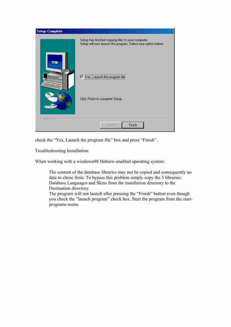
check the “Yes, Launch the program file” box and press “Finish”. Troubleshooting Installation: When working with a windown98 Hebrew-enabled operating system:
The content of the database libraries may not be copied and consequently no data to chose from. To bypass this problem simply copy the 3 libraries: Database Languages and Skins from the installation directory to the Destination directory. The program will not launch after pressing the “Finish” button even though you check the ”launch program” check box. Start the program from the start-programs menu.

Introduction The irrigation system planning software is designed to help you define the parameters of your irrigation system. You will be able to run the program with any suitable parameters, review the output, and change input data in order to match it to the appropriate irrigation system set up . Some parameters may be selected from a system list; whereas other are entered by the user according to their own needs so they do not conflict with the program’s limitations . The software package includes an opening main window, five calculation programs, one language setting window and a database that can be modified and updated by the user. Minimum system requirements MS Windows 98 or higher installed. Pentium processor compatible or higher. 32 MB RAM or more. SVGA Display (800x600 256 colors recommended). Installation Instructions Before you begin the Planning Software installation it is strongly advised you exit any running program . If a previous version of Hydro Calc is already installed on your computer, it is recommended to uninstall it before installing the new version, to avoid duplicity problems. If you have the old NetafimPlanning Software (HydrauliCalc) installed on your computer you do not have to uninstall it as long as you don’t install the new Hydro Calc in the same directory. To run the SETUP program : Open your Windows File Manager or File Explorer and click the CD icon .Double click the CD’s SETUP.EXE application and follow the instructions displayed on the screen . When you get to the last installation window:
TABLE OF CONTENT
INTRODUCTION
SYSTEM REQUIERMENTS
INSTALLATION
GENERAL
EMITTERS
SHAPE WIZARD
SUBMAIN
MAIN PIPE
VALVES
SHIFTS
SETTING
GLOSSARY