calculation of the shadow-penumbra relation and its application on efficient architectural design
TRANSCRIPT

Available online at www.sciencedirect.com
www.elsevier.com/locate/solener
ScienceDirect
Solar Energy 110 (2014) 139–150
Calculation of the shadow-penumbra relation and its applicationon efficient architectural design
Jorge Hernan Salazar Trujillo ⇑
Universidad Nacional de Colombia, Faculty of Architecture, Calle 59A No 63 – 20, Medellın, Colombia
Received 15 January 2014; received in revised form 21 July 2014; accepted 30 August 2014
Communicated by: Associate Editor Mario Medina
Abstract
Shadow Dispersion is the effect by which any opaque object’s shadow progressively becomes penumbra. This effect originates from apartial obstruction of the visibility of the solar disk. It allows diminishing solar gain in places where there is high radiation intensity,facilitating visual ergonomics and energy efficiency. Although architecture in the tropics offers a wide array of strategies for creating pen-umbras, i.e., meshes, lattices, architectural fabrics, openwork walls and pergolas, there is no method for its design. Solar architectureliterature simplifies the shadow projection phenomenon and always assumes sunrays as being parallel, but penumbra calculation doesnot allow for this simplification. In order to bridge this gap, calculating equations are deduced here and the tables needed to appraisesuitable architectural areas not to block but soften sunlight are included. This paper defines the penumbra rate and shows its applicationon a building built in Medellin in 2006, designed for housing exhibitions of orchids, which depend on penumbra to survive. The workconcludes by outlining the future possibilities of incorporating penumbra zones into the architectural design process. Other applicationsof the method are also mentioned.� 2014 Elsevier Ltd. All rights reserved.
Keywords: Penumbra; Gloom; Shadow; Shading device; Solar control; Shadow Dispersion
1. Introduction
In the tropics, permanent and moderate climaticconditions enable the construction of open buildings,highly permeable and able to establish tight bonds withthe place they are in Mesa (2013). Shadow is more signifi-cant in this part of the planet than in temperate zones due
http://dx.doi.org/10.1016/j.solener.2014.08.043
0038-092X/� 2014 Elsevier Ltd. All rights reserved.
Abbreviations: h, element’s height; ld, limit distance; f, solar disk viewingangle; hz, zenith angle; e, solar elevation angle; d, penumbra zone width; x,element’s size; lh, limit height; lx, limit size; PR, penumbra rate; s,element’s projection perpendicular to the solar rays.⇑ Tel.: +57 4 4449483; fax: +57 4 2604875.
E-mail address: [email protected]
to the lack of seasons, and because there is a higher inten-sity of incident solar radiation (Tzonis et al., 2001). There-fore, for many buildings and outside spaces located in thetropics, to have enough shadow is sufficient to offer humancomfort conditions for many hours a day.
The balance between sunlight and shadow is a funda-mental part in building design due to its strong effect onenergy efficiency and thermal comfort. In higher scale pro-jects such as urban planning, roads, squares and parksdesign, this is also a very important issue. In outdoor spacesand in any public space project, the energy efficiency aspectis less important since there is usually no air conditioning.Nevertheless, thermal comfort and visual ergonomics

140 J.H. Salazar Trujillo / Solar Energy 110 (2014) 139–150
precede the list of priorities to be fulfilled (Higueras, 2013).In turn, in a smaller scale objects’ design, it is essential totake shadow calculation into account, which is a prerequi-site for the correct dimensioning and distribution of anyshading device (Olgyay, 1968; Salazar, n.d.).
The methods and instruments employed to calculateshadows are widely used and spread within the professionalenvironment. In these methods, it is assumed that sunlightrays have an impact on the terrestrial surface as a set ofparallel rays. The results obtained from these calculationssuggest a drastic change between the shading zone andthe sunny zone, with a clear limit between both regions.This is something that is never observed in real shadows,as it can be easily proven. It suffices to expose any opaqueobject to the sunlight to verify that any shadow is smallerthan the object that projects it, and that the shading regionedge – called penumbra zone – is clearer as the distancebetween the object and its shadow increases. None of thosephenomena are taken into account when shadow calcula-tions are carried out with analysis methodologies in whichsunrays are considered parallel.
A false premise of parallelism does not always lead to animprecision with effective consequences on the designedobjects’ solar performance. If it is a big size object, theimprecision of not considering the penumbra is unseensince the shading area is proportionally bigger. Neverthe-less, for those cases in which architectural decisions tendto design elements whose dimension is just of a few centi-metres, it is essential to consider sunrays as not beingparallel.
Solar disk viewing angle and solar aureole are importantconcepts to improve solar concentration systems. Solartracking, mirror design and absorber plane optimizationcannot be done by applying the parallel solar vectorassumption. The solar disk viewing angle has variations dur-ing the year, but these variations are not significant and if itis considered as a constant value, the accepted limit of thesolar disk is 4.65 mrad (Buie et al., 2003a). The solar aureolepresents higher variations originated in the scattering of thesolar beam through the earth’s atmosphere depending onlocal climate variations (Buie et al., 2003b). The radiant fluxcontained within the circumsolar region of the sky, includ-ing solar disk and solar aureole, is an important issue defin-ing a pyrheliometer’s acceptance angle. A 5� field of view isdefined by the ISO-9060 to capture the sun and part of thecircumsolar region because the total amount of direct radi-ant flux is found within this angle.
There are subtle evidences of the sunshape distributionvariation on the shadow casting phenomena within archi-tectural elements: during clearer days the shadows will besharper and the penumbra zone narrower. In foggy daysand during mornings in warm-humid places, the penumbrazone becomes wider and the shadow definition becomesless evident. The 5� magnitude does not have a particularsignificance in architectural design because the extent ofthe solar disk provides between 98% (extremely clear skies)and 90% of the direct insolation (Buie and Monger, 2004).
From the designer’s point of view, both conditions can beconsidered equivalent because the critical design conditionarises when the sky is clearer, less energy comes from theaureole and the shadows have a better focus.
Database searching (including Science Direct, One File,Science Citation Index, Expanded Academic ASAP andDiscovery Service) using “penumbra, shadow and architec-ture” as keywords did not find any relevant paper duringthe retrieval made in July 2014. Publications about penum-bra in architecture refer to a characteristic of spaces light-ened with diffused natural light. In computer graphicresearch the term “soft shadow” is also used, and describescomputer techniques to increase realism in rendering algo-rithms (Kolivand and Shahrizal Sunar, 2013). Classicbooks on Bioclimatic Architecture, in which there is alwaysa chapter completely dedicated to the principles of SolarGeometry, do not mention the shadow-penumbra relationeither. Arzoumanian (1988), Baruch (1976), Koenigsbergeret al. (1977), Lippsmeier (1969), Lan (1986), Olgyay (1968),Puppo and Puppo (1972), Szokolay (1977) and Yanez(1988) works not only do not have the concept of penum-bra, but also do not include any discussion about the con-sequences of assuming sunrays’ parallelism when makingsolar control calculations.
The consequences of this gap are particularly importantin sunlightning studies carried out for the tropics. Meshes,lattices, architectural fabrics, openwork walls and pergolas,are part of the formal tradition and repertoire for buildingsin this part of the planet. The architectural enclosures madewith these elements can form surfaces of many squaremeters, but they are often composed by fairly small-dimen-sion elements repeatedly installed. They should not bedesigned without taking into account the penumbra effectsthey produce.
A successful design process is based on analysis and rep-resentation methods in which simplifications of the appliedmodel do not distort the essence of the studied phenome-non. To calculate shadows from a large list of architecturalelements, assuming sunrays as parallel, does not have prac-tical consequences or prevent making good design deci-sions. On the contrary, if rays are considered as divergent,this would lead to an unnecessary complexity in the calcula-tions since the conclusions would be ultimately the same asthose from using simpler methodologies.
At the detail scale, things are very different. For smallsize objects, the proportion between shadow and penumbrareaches a balance. In such cases, assuming sunrays’ paral-lelism implies ignoring an important phenomenon calledShadow Dispersion, which can have a major role in archi-tecture for the tropics, and which offers great possibilitiesin the creation of energy efficient and visually comfortablespaces.
2. Objective
To incorporate penumbra zones into the architecturaldesign process by developing the technical basis, deducing

J.H. Salazar Trujillo / Solar Energy 110 (2014) 139–150 141
the mathematical functions and creating the tables neededto calculate architectural devices in which penumbra effectis more accentuated than shadow effect.
3. Shadow Dispersion
Every shadow is the result of the visibility restrictionestablished between a point and a radiation source. Inthe hypothetical case where the source is a point, there willbe only a straight line linking the source with the studiedpoint and, therefore, it would be impossible for a partialvisibility of such point to occur. This case represents theonly possibility to have a shadow without having penum-bra at the same time.
In the real world, any radiation source is extensive and,therefore, there is always the possibility to have full or par-tial restriction of visibility. In the first instance, when all thepossible straight lines drawn between the source and theanalysed point are intercepted by an opaque object, sha-dow conditions are given. In the second instance, whenonly some of the straight lines are intersected, an incom-plete visibility of the radiation source is given and, as aresult, a reduction of incident energy in the analysed pointis noticed.
Every opaque object projects a shadow with an areaclose to its own size only when it stands on the shadow’sprojection plane. As the distance between the object andthe plane gets longer, the shading zone area gets smallerand the penumbra zone gets bigger until it reaches a dis-tance named limit distance ld where the shadow completelydisappears (Fig. 1). When that occurs, there is not a singlepoint on the surface experiencing a total obstruction of thesolar disk.
In the interval between distance zero (h = 0) and the limitdistance (h = ld) a progressive replacement of the shadow bythe penumbra takes place. This is perceived as a lack offocus in the shadow’s edges and an evident solar shinereduction inside the edges. Proportion variation between
Fig. 1. Variation in the proportion between shadow and penumbra. As an opapenumbra zone increases too, until it reaches a limit distance ld in which the
both zones is a result of Shadow Dispersion. This is a phe-nomenon by which a shadow is “blurred” and extendeduntil it totally becomes penumbra. It is called this waydue to the fact that, although the quantity of energy block-ing the object remains constant, its shadow spreads over anarea bigger than the one occupied by the shading zone.
Once the limit distance is exceeded (h > ld), recognisingin the shadow the object’s edges which block the sunraysbecomes impossible. Besides a decrease in solar radiationintensity under the shadowed area is verified. That is thereason why penumbra is so appreciated in the tropics; itconstitutes an architectural procedure which allows thereduction of solar radiation intensity where this is not onlyabundant but often annoying because of such abundance(Fig. 2).
A balanced distribution of both sunny and shadingzones makes part of the basic techniques to increase energyefficiency of an architectural enclosure. In this way, enclo-sures with a suitable energy performance can be achievedfrom both the visual ergonomics and thermal comfort per-spectives (O’Brien et al., n.d.). However, this technique isnot completely satisfactory since shading and sunny zonesalternation could be unpleasant for carrying out certainkinds of activities, especially those which are highly-visu-ally demanding. The possibility of preventing this visuallyuncomfortable condition by means of the suitable design-ing and dimensioning of the penumbras projection devicesis what allows obtaining equivalent profits in terms ofenergy, but with a more moderate and convenient distribu-tion for human sight.
Incorporating penumbra zones into the architecturaldesign process entails that the shape, position, and size ofthe shading device’s composing elements be designed basedon the Shadow Dispersion effect application. This phenom-enon is the function of three variables: (1) the solar diskviewing angle; (2) the size and position of opaque objectsprojecting the shadow; and (3) the distance between thoseobjects and the shadow projection plane. It is evident that
que object’s height h increases, its shadow’s size decreases. The size of theshadow disappears and totally becomes penumbra.

Fig. 2. Architectural devices for penumbra projection. Left: pavilion’s blinds. Expo-Sevilla, Spain. Latitude 37�N. Centre: traditional market’s roof, SanPedro de Atacama, Chile. Latitude 23�S. Right: traditional facade in San Juan de Uraba, Colombia. Latitude 9�N. Author’s photographs.
142 J.H. Salazar Trujillo / Solar Energy 110 (2014) 139–150
the last two variables can be absolutely controlled throughthe design process. Due to this fact, it is necessary to formu-late the involved trigonometric relations for calculatingtables and diagrams allowing to know the penumbra condi-tions of an architectural enclosure prior to its construction.
Fig. 3. Annual variation in the apparent size of the solar disk. During theperihelion (January), the Earth is closest to the sun; at that time, shadowsare smaller and penumbras are wider than what they will be six monthslater. The radius of the arcs represents the proportion of such variation inreal magnitude. The “solar disk viewing angle” f can be calculated fromthe relation between the Radio of the Sun and the distance between theEarth and the Sun.
3.1. Solar disk angular size
In the aphelion, the Earth is 152.6 million kilometresaway from the Sun, while during the perihelion – its pointin the orbit closest to the Sun – that distance is reduced to147.5 million kilometres (Wilhelm and Dwivedi, 2014).Since the equatorial radius of the Sun is 0.695 million kilo-metres, it can be calculated that, from the Earth, the solardisk is seen in an viewing angle f varying from 0.26095�during the aphelion (which occurs on or about 4th July)and 0.26997� during the perihelion (which occurs on orabout 3rd January). Variation in the apparent size of thesolar disk is about 4%, a magnitude that needs to be con-sidered for architectural applications in which there is aninterest to take this subject to the limit (Fig. 3). Neverthe-less, for most applications, the solar disk viewing angle canbe considered as constant and equal to the aphelion angu-lar opening (f = 0.26095�), when the sun is furthest and isseen with a smaller angle. Under this condition, an object’sshadow will need a longer trajectory before completely fad-ing into penumbra.
The simplification of assuming the apparent solar disksize as constant allows to not differentiate between shadowsand penumbras produced at different times of the year.This simplification leads to a maximum error of 4%, whichis equal to specifying 4 additional millimetres in a 0.20 m-wide piece installed at 4.0-m height (Fig. 4). This is a shortmargin of error for the precision level of a construction. Inthe following figures the variation in the results that can beexpected in the case this variation is taken into account isshowed with a dotted line.
Fig. 4. Shadow size annual variation. When sunrays occur perpendicu-larly, a 0.20 m object located at 4.0 m height will have an annual variationof 4 mm in its shadow’s width.
3.2. Penumbra rate
Penumbra calculation is relevant when designing objectswhose visual obstruction angle is similar to the angle with

J.H. Salazar Trujillo / Solar Energy 110 (2014) 139–150 143
which the solar disk is seen from the earth’s surface, amoment when penumbra zone edges on both sides get closeenough and the reduction in shadow size becomes evident.This occurs with objects that are very distant from the sha-dow projection plane (i.e.: an airplane flying by) or withsmall objects such as prismatic elements of just some centi-metres wide which make up a pergola.
Using the accepted solar nomenclature (Fig. 5)Blanco-Muriel et al. (2001), the penumbra zone width d,going from point B to point C (Fig. 6), can be calculatedfrom triangles ABA0 and ACA0, which are formed fromsolar elevation angle e, adding or subtracting angle f/2.Preparing equations for definite shapes and orientationswould imply latitude and solar geometry generalization.To give architectural freedom to the infinite possible shapesto be designed, it was preferred to develop a method of cal-culation based upon only five basic equations valid forboth hemispheres instead of a set of complex equationswith a narrower location or shape validity. That is whythe following equations start from a solar elevation anglethat must be previously calculated according to the latitudeof the location under study.
The expression for calculating the penumbra zone widthd that is projected by an opaque object’s edge hanging at h
height with respect to the shadow projection plane is asfollows:
d ¼ h= tanðe� f =2Þ � h= tanðeþ f =2Þ ð1Þ
For an opaque object with width x, limit height lh
(Fig. 7) can be calculated from the point where its shadowwill not reach the ground, according with the followingequation:
lh ¼ x tanðeþ f =2Þ tanðe� f =2Þ=ðtanðeþ f =2Þ� tanðe� f =2ÞÞ ð2Þ
If the object’s height h became constant and the width ofthe object projecting the shadow were progressivelyreduced, the analysis sequence would be similar and the
Fig. 5. Solar nomenclature used in this paper, corresponding with Blanco-Muriel et al. (2001). The solar elevation angle e is measured from thehorizon line, the standard reference in architectural drawings.
limit size lx would be reached, from which its shadowcan no longer be projected on the ground (Fig. 8). As itis shown in Figs. 7 and 8, this occurs when the object’swidth is equal to its penumbra’s width d and, therefore, itis also defined by Eq. (1), shown with grouped variablesas follows:
lx ¼ hðtanðeþ f =2Þ � tanðe� f =2ÞÞ=ðtanðeþ f =2Þ� tanðe� f =2ÞÞ ð3Þ
The diagrams derived from those last two equations aresufficient for the dimensioning of some architectural ele-ments, but in neither equation is the object’s thickness orthe geometry of its section taken into account. Some addi-tional precisions will be necessary for the calculationmethod generalization so that variation in the directionof the sunrays could be considered. This will allow to con-sider the effect of the elements’ proximity and the variationin their apparent section based on solar elevation angle e.These subjects will be addressed in Section 3.3.
At the interval between B and C (Fig. 9) there is a tran-sition from the sunny zone (with 100% visibility of the solardisk) to the shading zone (0% visibility). This gradation inshadow density, which is called penumbra rate PR, can becalculated for every point in the segment going from thebeginning to the end of the penumbra zone. To do so,the distance between the calculation point and the begin-ning of the penumbra (distance y) will be needed to calcu-late de g angle, corresponding to the circular sector visiblefrom point Q (Eq. (4)).
g ¼ arccosð1� 2y=dÞ ð4Þ
Finally, to compute the area of the circular segment thatbecomes visible from every point (Fig. 10) and transformthe result in a percentage value, another expression (Eq.(5)) will be enough to obtain the penumbra rate value PRfrom a g value obtained in degrees.
PR% ¼ 2g=360� � sinðgÞ cosðgÞ=p ð5Þ
Studying penumbras near an object whose dimensionsare significantly larger than the penumbra zone’s width isnot of much practical interest in architecture. For example,for a 10-m-high building with e = 60�, the width of thiszone is just 0.12 m. Nevertheless, when penumbras createdon every side of the object begin to interact and to overlapbecause of their proximity, their study is most relevant.
When limit distance is exceeded, an object can no longercompletely block the solar disk visibility from any point onthe studied surface. The shadow has already disappearedand penumbras on both sides of the object begin to overlapin an additive way. In order to calculate the penumbra ratefrom a point under these conditions, it suffices to calculatepartial visibilities of the solar disk segments on both sidesof the object. When graphing the solar radiation attenuat-ing effect that produces a series of opaque elements whosepenumbra zones are overlapped, a sector becomes evidentin which solar radiation takes values notably lower than

Fig. 6. Penumbra zone width d. For a solid element at a height h, penumbra zone width d can be calculated. Between points B and C there is a transitionbetween the sunny sector and the shading sector. The results for two solar elevation angles e are graphed on the right. Results obtained for the aphelion aredifferentiated with solid lines.
Fig. 7. Minimum size needed to project shadow at different heights. For an object with a dimension x there is a limit height lh from which its shadow willnot reach the floor.
Fig. 8. Maximum element’s height to obtain shadow for different element’s sizes. For a height h, it is possible to calculate the minimum size an object musthave for its shadow to reach the floor. The design point of the Orchids Exhibition Centre of Medellin is highlighted: 4.6 cm wide elements installed 14.0 mabove the floor. If a stripped floor was desired during middays, it would be necessary to specify elements at least 13 cm wide. Keeping the strips visiblewhen the solar elevation angle is lower (e = 45�) would require elements wider than 25 cm.
144 J.H. Salazar Trujillo / Solar Energy 110 (2014) 139–150
those in the sunny zone, but very similar to each other(Fig. 11). The oscillations in PR values under a surfacefor penumbra projection vary according to the distancethat separates the opaque elements: it will become longeras the distance increases, and it will approach zero whenthe elements are too close to each other. If distance is exces-sive, the direct lightning bands will become visible again
(PR = 1), but the median value would be equal to the sur-face’s drilling percentage.
3.3. Variation in the origin direction of solar radiation
When the elements forming a surface have a circular sec-tion, limit distance ld and limit size ls values are constant

Fig. 9. Penumbra rate calculation, part one. From the beginning of thepenumbra zone (identified with point B) to the end of the transitionalcondition (point C), the edge of a solid object obstructs part of the solardisk. The expression to calculate the obstruction rate starts from angle g
calculations, according to the distance between the point under study Qand the beginning of the penumbra zone (y value).
Fig. 10. Penumbra rate calculation, part two. The visible solar disk area[a] from point Q can be calculated as the subtraction of two areas: thecircular sector area [acs] defined by point Q0 minus the inscribed trianglearea [at]. The resulting circular segment area is expressed in percentageaccording to the angle g, obtained from the distance y that separates thepoint Q from point B.
J.H. Salazar Trujillo / Solar Energy 110 (2014) 139–150 145
for all the solar elevation angles since, regardless of thedirection the sunrays come from, the object projection’swidth will be always the same. The minimum height atwhich a circular section object with a diameter x should
be installed, for it to not project shadow on a horizontalplane, according to the solar elevation angle variation,can be calculated from Eq. (2) (Fig. 12).
These diagrams provide enough information to specifythe minimum or maximum dimensions of a shading ele-ment with circular section. When the elements have a differ-ent section, it will be necessary to reiteratively make thelimit distance and/or size calculations for different inci-dence angles. This procedure implies calculating the ele-ment projection’s width perpendicularly to the sunraysfor every case and then, taking the limit distance value ld
corresponding to each projection’s size s. The results – ld
diagrams for a particular section – allow to demonstratehow objects often used in the construction of pergolasand other shading devices regularly have asymmetricalbehaviours on distances from which they do not projectshadows on the ground (Fig. 13).
The continuous variation in the direction in which solarradiation comes from, demands considering also the prox-imity effect between adjacent elements to identify the anglefrom which each element’s shadow begins to project itselfon the adjacent element. In this way, the moment can bedetermined when a discontinuous surface, composed of arepetition of similar elements, begins to function as a solidobject (Fig. 14).
Limit distance diagrams allow to include in the analysisthe variety of distances that can appear between an opaqueelement and the surface or surfaces where shadow and pen-umbra occur. If it becomes interesting to establish variabledimensioning and spacing criteria according to the proxim-ity relationship of the surfaces set which compose an enclo-sure, limit distant variations for every direction will need tobe considered.
Sunrays are not always annoying. Even in the tropics,there are times and places where shadow patterns recogni-tion can be bearable or even favourable. Following theoptimization path, it is advisable to start the design of asurface for penumbra projection by identifying the inter-vals and places where such condition will be desirableand, subsequently, calculate the corresponding solar trajec-tories. This will allow the monitoring of sectors whereshadows will or will not be recognisable as well as the inter-vals where such conditions will be present.
There are two ways of applying the concept and dia-grams for limit distance calculation: spatial and temporal.Spatial application consists in calculating the intersectionbetween a limit distance diagram and the surfaces markingoff a space. This procedure allows to identify zones that canpossibly receive shadow or penumbra. On the other hand,temporal application consists of the projection of thesevery intersections towards the celestial canopy, whichallows to mark off the intervals (in dates and hours) whenspecific penumbra conditions could appear (Fig. 15). Inboth applications, associated angles and distances areissues that must be treated in a tridimensional way byapplying shade covers and solid angles, even though bidi-mensional angles are suitable enough for most situations.
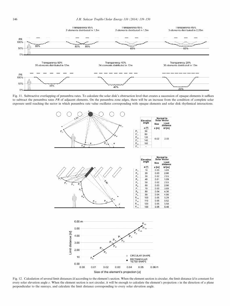
Fig. 11. Subtractive overlapping of penumbra rates. To calculate the solar disk’s obstruction level that creates a succession of opaque elements it sufficesto subtract the penumbra rates PR of adjacent elements. On the penumbra zone edges, there will be an increase from the condition of complete solarexposure until reaching the sector in which penumbra rate value oscillates corresponding with opaque elements and solar disk rhythmical interactions.
Fig. 12. Calculation of several limit distances ld according to the element’s section. When the element section is circular, the limit distance ld is constant forevery solar elevation angle e. When the element section is not circular, it will be enough to calculate the element’s projection s in the direction of a planeperpendicular to the sunrays, and calculate the limit distance corresponding to every solar elevation angle.
146 J.H. Salazar Trujillo / Solar Energy 110 (2014) 139–150

Fig. 13. Limit distance diagrams for different profiles. Every profile has a particular limit distance diagram. The separation between neighbouring elements(identified as “step” in the figure) restricts the possibility of having partial visibilities of the solar disk in certain directions, trimming some diagram’sportions. Intersections with the floor identify the sectors where shading conditions can appear and projections to the sky dome identify the time intervalswhen such conditions could be observed.
Fig. 14. Application of limit distance diagrams. The proximity of an opaque object to the surfaces of a place can cause intersections with its limit distancediagram. This makes possible to identify the sunrays’ directions (hours or months) that will project shadow and those that will project penumbra only.
J.H. Salazar Trujillo / Solar Energy 110 (2014) 139–150 147

148 J.H. Salazar Trujillo / Solar Energy 110 (2014) 139–150
4. Case of implementation. Orchids exhibition centre of
Medellin, Colombia
Since “Feria de las Flores” (Flowers Festival) hasbecome an event of international renown, the BotanicalGardens of Medellin, Colombia (located at 6.25�North lat-itude, 1460 masl, MeanT 22 �C MinMeanT 16 �C, Max-MeanT 29 �C (Atlas Climatologico de Colombia, 2005)demanded a space destined to the orchids annual exhibi-tion. The building should also favour the carrying out ofdifferent activities such as weddings, concerts, parades,fairs, and conferences for the rest of the year (Fig. 16).The challenge was to guarantee solar light conditionsintense enough for the plants to nourish, but faint enoughfor visitors to be comfortable.
This project, with a 4000 m2 covered area, was designedin 2006 by Plan:b Arquitectos in association with JPRCRArquitectos (Mesa et al., 2014). As a design principle, theexhibition zone should guarantee visual ergonomic condi-tions without high contrast situations despite the fact thatits roof was 50% made of translucent polycarbonate. As anadditional requirement, any place on the floor and up to4.0 m high could not contain sunny zones due to the solar
Fig. 15. Duration intervals of a penumbra condition. Intervals where ashadow condition begins and ends allow to calculate – in the direction ofthe sky dome – the intervals in dates and hours on which penumbraconditions can appear.
Fig. 16. Orchids Exhibition Centre in the Botanical Gardens of Me
radiation coming in between the wood strips that configurea 14.0 m high pergola. This design demand was clearly sta-ted: the shadow of the elements forming the pergola mustbe totally indistinguishable at any hour of the day or per-iod of the year.
Orchids are extremely fragile, and it is unacceptable tohave a plant exhibited under a spot of sun, even for afew minutes. In this place, orchids from all over the world– collectible pieces, rare, and sometimes endangered speci-mens – are exhibited. The Orchids Exhibition Centre –“Orquideorama” in Spanish – is responsible for protectingthis valuable collection from sunrays, which quickly dam-age some of the flower species. The canopy – the upper partof the foliage in a tropical forest – creates the suitablemicroclimate for orchids to grow and develop since thatis their natural habitat. The building forms an artificialcanopy that produces a penumbra level similar to the oneof a native forest and also gives continuity to the set oftrees surrounding the building. Thanks to the transitionfrom the foliage of the existing trees and the artificial can-opy formed by the pergola, the Orchids Exhibition Centredoes not have any lateral enclosures.
The botanical experts suggested maintaining the insola-tion level inside the Exhibition Centre below the 40% limitto have an insolation exposure value appropriate to theorchids‘ health. Budget and structural reasons lead to aclear sheet polycarbonate (g-value = 0.68) as the selectedroof material. To reach the required shadow level of 0.4it would be necessary to specify a darker polycarbonatesheet that would have modified the orchids colours. As partof the bioclimatic counselling work made by PVG Arqui-tectos an alternative solution was proposed: a secondarywooden shadow layer to maintain the natural light spec-trum and provide the 0.28 missing value, giving origin tothe 40% fullness and 60% emptiness pergola ratio.
Infinite size-distance combinations can provide a 40–60% pergola. The element’s limit size was obtained fromEq. (3) using the following values: solar elevation anglee = 90�, element height h = 10 m and solar viewing anglein aphelion f = 0.26095�. It must be noticed that thedesigned height of the pergola was not 10.0 m, but usinga 14.0 m value would have led to a floor without shadowstrips accompanied by shadow patterns on visitors,
dellin on a sunny day. Courtesy: Jardın Botanico de Medellın.

Fig. 17. Architectural section of the building. The size and spacing between the elements that compose the pergola of the Orchids Exhibition Centre ishighlighted. Having the sun in the zenith is the critical design condition for orchid’s exhibition. The region free of shades during that moment is showed.Courtesy: PVG Arquitectos.
J.H. Salazar Trujillo / Solar Energy 110 (2014) 139–150 149
collections and possible publicity elements within the visionfield. To prevent this annoying situation, a 4.0 m heightallowance was initially reserved to keep that volume freeof shadow patterns, resulting in a 94 mm-limit size value.Wood optimization reasons finally led to specify46 mm � 40 mm pieces. The 66 mm distance it is theneeded value to guarantee the required shadow ratio dur-ing mid-days. This pattern has a 5.04 m minimum heightvalue and as a result, in the Orchid Exhibition Centre thereis an 8.96 m height zone free of shadow patterns (Fig. 17).
The design point of the above-mentioned elements isindicated with an icon (Fig. 8). The performance observedduring eight years of operation demonstrates the advantageof using penumbra as a strategy for public space creation inthe tropics. The Orchids Exhibition Centre manages a fullprogramming agenda all year round and, regardless of howclear the sky in Medellin is at a certain time, this building’sinterior always maintains a gentle penumbra environment.
5. Discussion
Surfaces for creating penumbra can be calculated fromthe proportion between the full area and the empty area.Those numbers are subsequently transformed into some-thing similar to a shadow coefficient, as if it were a translu-cent material. It is an imprecise method; therefore,prototype construction was often necessary (Salazar,2007). For those who design and construct in the tropicsit is evident that there are different shading qualities. Byapplying penumbra rates, the geometrical characteristicsof these elements can be defined from required penumbraconditions in a simpler and more precise way.
The calculation method has been applied in the designof discontinuing surfaces composed by opaque elements,but it is also being used to design double skin facades. Inthis second type of application, the exterior facade consistsof surfaces with calculated drillings following the sameShadow Dispersion principles. The maximum width ofthe partition wall and the drillings silhouette represent herethe design variables to be defined, considering that the dis-tance between the drilling and the shading plane is variable.This requires a progressive reduction in the partition wall’swidth as the distance between drillings and the work planedecreases.
Any set of drillings made in a repeated and homoge-neous way causes interference patterns, which can be visu-ally uncomfortable and even incapacitating. Drillings madewith random shape, position and size – as long as they arewithin the correct dimensional interval – are the simplestway to prevent interference patterns. Nevertheless, evenwith randomly distributed drillings it is not possible toobtain a completely homogenous penumbra. It has beenempirically verified that, from a certain homogeneity level,PR variations between neighbouring regions on the samework plane are not annoying. Penumbra equations willbe used to continue studying this subject.
Architectural enclosures for penumbra projection have alot of potential in profiting from natural light resources inbuildings. Drillings and distances between opaque elementsdo not imply absorption or light transmission phenomena;that is the reason why they offer great possibilities as natu-ral light profiting devices. Their performance in skylightsand windows in which visual conditions are not importantwill be superior to the performance of glasses with high

150 J.H. Salazar Trujillo / Solar Energy 110 (2014) 139–150
shadow coefficient, which often alter the spectral composi-tion of light and cause changes in colours.
Nowadays, the use of discontinuing and drilled surfacesfor penumbra projection is not proportional to its possibil-ities. The difficulties in construction to ensure a good finish-ing with small and repeated elements, added to the obstaclesto know in advance the sunrays’ softening effect, couldexplain this situation. With the marked tendency to intro-duce digital production and parametric design techniques(e.g., laser cut sheets, tridimensional plotter, or digitallyprinted glass, among other techniques), a large number ofarchitectural applications of the equations and methodol-ogy of analysis presented here are foreseen in the short-term.
6. Conclusions
Penumbra rates allow to design and specify architecturaldevices for softening solar radiation starting from arequired penumbra condition. Their application allows tocarry out quantitative comparisons and predict the penum-bra level of many frameworks of habitual use in tropicalzones. It also allows to establish the geometrical character-istics of the elements composing the surface for solar con-trol, this time taking into account sunrays divergence.
Interdependency relationship between limit size lx andlimit distance ld prevents from giving a unique prescription,from which the Shadow Dispersion effect will be evident.By way of generalisation, when designing shading devicesat a height of 4.0 m from the ground (the typical heightfor urban shading elements) composed by elements witha dimension equal to or lower than 0.075 m, Shadow Dis-persion phenomenon must be considered. When designingbigger elements, the effect would be less significant and cal-culations could be made assuming sunrays as being paral-lel. For elements installed at any other height, it wouldbe sufficient to make linear proportionality calculations.
It is necessary to determine what the visual tolerance isto the changes in penumbra rates between neighbouringpoints. This will allow to include human factors in themethod exposed. So far, tolerance based on visual demandlevel, kind of task, lighting level and age group is unknown.In the short-term, advantage will be taken of the possibilityof quantifying the intensity of a penumbra to continuestudying this subject.
References
Arzoumanian V. Sol y Arquitectura, Ed. Gustavo Gili, Barcelona , 1988.IDEAM. Atlas Climatologico de Colombia, Bogota, 2005.Baruch, G., 1976. Man, Climate and Architecture, second ed. Applied
Science Publishers, London.Blanco-Muriel, M., Alarcon-Padilla, D., Lopez-Moratalla, T., Lara-
Coira, M., 2001. Computing the solar vector. Sol. Energy 70 (5), 431–441.
Buie, D., Monger, A., 2004. The effect of circumsolar radiation on a solarconcentrating system. Sol. Energy 1–3, 181.
Buie, D., Dey, C., Bosi, S., 2003a. The effective size of the solar cone forsolar concentrating systems. Sol. Energy 5, 417.
Buie, D., Monger, A., Dey, C., 2003b. Sunshape distributions forterrestrial solar simulations. Sol. Energy 2, 113.
Higueras, E., 2013. Urbanismo Bioclimatico. Coleccion Arquitectura yDiseno + Ecologıa. Editorial Gustavo Gili, Madrid.
Koenigsberger, O.H., Ingersoll, O.H., Mayhew, T.G., 1977. Viviendas yEdificios en zonas calidas y tropicales. Editorial Paraninfo, Madrid.
Kolivand, H., Shahrizal Sunar, M.A., 2013. Survey of shadow volumealgorithms in computer graphics. IETE Technical Review, vol. 30(1),Medknow Publications & Media Pvt. Ltd., pp. 38–46.
Lan, W.M.C., 1986. Sunlightning as Formgiver in Architecture. VanNostrand Reinhold Company, New York.
Lippsmeier G. Tropenbau, Building in the Tropics, Ed. Callwey Verlag,Munich, 1969.
Mesa, F., 2013. Permeabilidad. Mesa Editores, Medellın.Mesa, C., Mesa, M., Toledo, R., 2014. Medellın Architecture Guide 1994–
2014. Mesa Editores, Medellın.O’Brien, W., Kapsis, K., Athienitis, A.K., n.d. Manually-operated
window shade patterns in office buildings: a critical review. Build.Environ., pp. 60319–338. doi: 10.1016/j.buildenv.2012.10.003.
Olgyay, V., 1968. Clima y Arquitectura en Colombia. Editorial Univers-idad del Valle, Cali.
Puppo, E., Puppo, G.A., 1972. Sol y Diseno. Editorial Marcombo,Barcelona.
Salazar, J.H., 2007. Diseno de Sombras. Universidad Nacional deColombia, Medellın.
Salazar, J.H., n.d. Solar performance and shadow behaviour in buildings.Case study with computer modelling of a building in Loranca, Spain.Building and Environment, pp. 33117–130. doi: 10. 1016/S0360-1323(97)00027-9.
Szokolay, S.V., 1977. Solar Energy and Building. Architectural Press,London.
Tzonis, A., Stagno, B., Lefaivre, L., 2001. In: Alexander Tzonis, LianeLefaivre and Bruno Stagno (Eds.), Tropical Architecture: CriticalRegionalism in the Age of Globalization, Wiley-Academic, Chichester,New York.
Wilhelm, K., Dwivedi, B., 2014. Secular perihelion advances of the innerplanets and asteroid Icarus. New Astronomy, February 18, 2014.
Yanez, G., 1988. Arquitectura Solar. MOPU, Madrid.