calculation of induction motor starting parameters using matlab
TRANSCRIPT

8/18/2019 Calculation of Induction Motor Starting parameters Using Matlab
http://slidepdf.com/reader/full/calculation-of-induction-motor-starting-parameters-using-matlab 1/6
INFOTEH-JAHORINA Vol. 15, March 2016.
- 879 -
Calculation of Induction Motor Starting ParametersUsing MATLAB
1Dejan Pejovski, 2Bodan VelkovskiUndergraduate students
“Ss. Cyril and Methodius” University, Faculty of Electrical Engineering and Information TechnologiesSkopje, Republic of Macedonia
[email protected] [email protected]
Abstract —Squirrel cage induction motors are widely used in
electric motor drives due to their satisfactory mechanical
characteristics (torque, current, overloading) and small
dimensions, as well as their low price. When starting an
induction motor, a large current is required for magnetizing its
core, which results in a low power factor, rotor power losses and
a temperature rise in the windings. None of these parameters
should reach values beyond certain limits until the motor reachesnominal speed, i.e. during the motor’s starting time. In this paper
a comparison between two induction motors for a particular
working mechanism will be presented. The choice will be based
on three criteria: the motor’s starting time, winding temperature
according to the insulation class, and rotor energy losses. The
simulation is carried out with a specially developed tool in the
MATLAB software environment.
Kew words-induction motor; starting time; rotor losses;
winding temperature; MATLAB
I. I NTRODUCTION
A large part of electrical energy is converted intomechanical energy in electric motor drives. Among differenttypes of electric motors, induction motors are the most used for
both home appliances and in various industries [1]. They areconsidered as workhorses in modern industry, because of theirsmall size, low production and maintenance costs, wide powerrange, reliable operation etc. Three phase induction motors
present (67 – 87) % of all installed AC drives [4]. This is so because they have been traditionally fed directly from the three phase AC electric power grid through electromagnetic powerswitches with adequate protection [1]. Typical motorapplications include pumps, fans, compressors, mills,extruders, refiners, cranes, conveyors etc. [3]. This paper will
present the design of a tool in MATLAB which is used to
calculate the starting time, rotor energy losses and the windingtemperature of a chosen electric motor for a given loadrepresented by its torque-speed curve. In this paper, this toolwill be used to compare the performance of two electric motorswhen used to propel a fan mechanism and to select theappropriate motor based on the results. The theoretical outlineof the principle of operation of the designed tool will also be
presented.
II. METHODS OF STARTING AN INDUCTION MOTOR
Ideally, a motor-starting study should be done prior to purchase of a large motor. The manufacturer should providethe starting voltage and current values. A detailed study isnecessary if the motor power exceeds 30% of the supplytransformer(s) base kVA rating, if no generators are present. Insome cases, if the motor power exceeds (10–15) % of theconnected generator kVA rating, such analysis is also required[2].
Starting refers to speed, current, and torque variations in aninduction motor when fed directly or indirectly from a ratherconstant voltage and frequency local power grid. A “stiff” local
power grid means rather constant voltage even with largestarting currents in the induction motors with direct full-voltagestarting [1]. At zero speed at steady state, 6 to 8 times ratedcurrent is expected [8]. Full-starting torque is produced in thiscase and starting over notable loads is possible. For startingunder heavy loads, a large design kVA power grid is necessary.On the other hand, for low load starting, less stiff local power
grids are acceptable. Voltage decrease due to large startingcurrents will lead to a starting torque, which decreases withvoltage squared, as shown in eq. (1) [1], [8].
( )⎥⎥
⎦
⎤
⎢⎢
⎣
⎡++⎟
⎟ ⎠
⎞⎜⎜⎝
⎛ +
=2'
21
2'2
10
'2
213
X X s
R Rs
RU M
f
p
ω
. (1)
U 1f – voltage applied to each stator phase [V] R1 , R’2 – stator and rotor active resistances [Ω]
X 1 , X’2 – stator and rotor inductive resistances [Ω]ω o – synchronous angular speed [rad/s]s – slip, i.e. relative difference between motor’s
synchronous speed and rotor speed.
To maintain the induction motor starting current at anacceptable range, the motor maximum power limit is calculatedfor a particular local power grid. The main negative effects thatlarge starting current can cause are: notable stress in theelectrical installations, great voltage drops, and the motorstarting could be unsuccessful [8]. Various techniques have
8/18/2019 Calculation of Induction Motor Starting parameters Using Matlab
http://slidepdf.com/reader/full/calculation-of-induction-motor-starting-parameters-using-matlab 2/6

8/18/2019 Calculation of Induction Motor Starting parameters Using Matlab
http://slidepdf.com/reader/full/calculation-of-induction-motor-starting-parameters-using-matlab 3/6
- 881 -
Integrating eq. (3), the starting time can be calculated, asshown in eq. (5), where no [min-1] is the synchronous speed.
( )∫ −=
0
0
2
2,38
n
sm
p dn M M
mDt . (5)
Solving eq. (5) can be very complicated, especially whenthe motor starts with different load type, described with itsmechanical torque M s. A graphical approach has beendeveloped for simplifying the integrating process [8]. Also anumerical method can be used, and the solution precision willdepend on the number of steps taken into account. In this paper, the starting time calculation is based on Simpson’s rulefor parabolic interpolation, if the synchronous speed is equallydivided into integer values in each step. Otherwise, atrapezoidal rule is used. The motor torque for each speed valueis calculated by simplified Kloss equation (6), in which M k = M max [N] is the maximum (breakdown) torque, and the slip
sk = (5–25) % refers to the maximum torque point. The rotorslip s is computed according to eq. (7) [9].
s
s
s
s
M M
k
k
k m
+=
2. (6)
0
0
n
nns
−= . (7)
The Kloss equation (6) can be accurately used for woundinduction motors, and cage induction motors with negligibleskin effect. Otherwise, it can be used only in the linear regionof motor’s mechanical characteristics, i.e. relatively small slips[8].
When the load torque is notable from zero speed on(>0.5 M m) or the inertia is large ( J vk > 3J m), the starting processis slower and the machine may be considered to advance fromsteady state to steady state until full-load speed is reached in afew seconds to minutes (in large motors) [1].
IV. E NERGY LOSS DURING STARTING TIME
Starting an induction motor is actually a transient processsimilar to short circuit, because of the large stator and rotorcurrents. Due to these currents, much more electrical energy isused from the power grid during dynamic processes than insteady state. Depending on the load type, the energy losses incopper windings result in windings temperature rise and lowdrive efficiency. The rotor losses can be computed according toeq. (8), and the eq. (9) shows the total energy consumed by theinduction motor during starting period [8], [9].
( )∫ −−
=0
0
0
2
2365
n
sm
mCu dnnn
M M
M mD A . (8)
∫ −=
0
0
0
2
365
n
sm
mrot dn
M M
M n
mD A . (9)
The kinetic energy generated in the motor rotating part is:
2Curot k A A A −= . (10)
According to eq. (8), (9) and (10) it can be calculated thatthe rotor winding losses during motor acceleration under noload are equal to the rotor kinetic energy at ideal no-load speed[1]. If the motor starts with mechanical load connected to itsshaft (Ms≠0), the rotor losses become even greater. Thissituation can be improved using variable speed drives. In fig. 2energy balance is shown when the motor has one speedwinding a), and when a Dahlander’s winding is used for twodifferent synchronous speeds in ratio 1:2 b). It is notable that inthe second case the rotor losses are half the previous ones. Incase c) a continuous speed change is shown, theoretically withno rotor losses [6].
Figure 2. Power losses during induction motor starting: with onestator winding (a); Dahlander’s winding speeds in ratio 1:2 (b);
continuous speed change (c).
V. WINDING TEMPERATURE DURING STARTING TIME
The temperature gained in electric motor is one of thecrucial parameters which determine motor’s rated power.Motor energy losses transform into Joules heat: a part of themis transferred to the environment, while the other part
increases motor’s temperature. Stationary state is reachedwhen all the generated heat is transferred to the environment,i.e. the temperature has a constant value [4]. This situationoccurs typically after 4T z, where T z [s] is motor’s temperatureconstant (eq. 11). Although its basic value is seconds, thetemperature time constant T z is usually measured in minutesfor smaller, or in hours for larger motors [5].
Sh
mcT Z = . (11)

8/18/2019 Calculation of Induction Motor Starting parameters Using Matlab
http://slidepdf.com/reader/full/calculation-of-induction-motor-starting-parameters-using-matlab 4/6
- 882 -
m – motor mass, [kg]c – specific thermal capacity, [J / kg ·K]S – motor surface which transfers heat, [m2]h – heat transfer factor, [J / K·m2·s]
The insulation materials are subjected to thermal stress andageing, which is not regenerative. That means whendetermining rated motor power, for voltage U n ± 5% and f =50Hz, the maximum stationary temperature must be takeninto account (at maximum ambient temperature 40oC and atheights below 1000 m) [4]. The more efficient cooling systemis used, the higher load can be connected to the motor.Basically, the motor can be of open or closed type. Openmotors have their own inner ventilator on the shaft, and closedtypes use ribs and ventilators on the outside [4].
Z Z T
t
oT
t
m ee−−
+⎟⎟⎟
⎠
⎞
⎜⎜⎜
⎝
⎛ −= θ θ θ 1 . (12)
Eq. (12) describes windings temperature change over time,where θ [oC] is the current motor temperature above ambienttemperature, θ o [
oC] is the motor temperature in the beginningof the acceleration, and θ m [oC] is the maximum motortemperature, which is considered to be reached after 4T z. Bydefinition, θ o = 0 [oC] [8].
The cooling process can be described with eq. (13), whereT zo = T z / β [s] is the temperature time constant during motor’scooling, which takes into account motor’s construction type bythe correction factor β . θ p [
oC] is the temperature at the process beginning [8].
0 Z T
t
pe−= θ θ . (13)
A MATLAB simulation that computes the motor’stemperature according to eq. (12) and (13) was developed,with respect to the constant and variable rotor losses (PFe /PCu),maximum temperature allowed depending on insulation class(θ d [oC]), and motor duty cycle. As most typical duty cyclesaccording to IEC 60034-1 standard are considered: continuousmaximum rating (constant load, S1), short-time duty S2 andintermittent duty S3. The recommended values for short-timeduty are: 10, 30, 60 and 90 min, and the recommended valuesfor the intermittent factor ε for S3 are: 15, 25, 40 and 60 %
[5]. ε defines the load duration (t r ) relative to the cycle time(t cik ):
or
r
cik
r
t t
t
t
t
+==ε . (14)
VI. MATLAB SIMULATION
The MATLAB simulation was used to calculate the startingtime, rotor energy losses and the winding temperature of twodifferent induction electric motors: Končar 5AZ 100LB-8 andSever ZK 100 Ld-8 when propelling an axial fan: KončarVAAZ A 800-A L260L720 M100B14P0,9. The results fromthe simulation are presented below. The technicalspecifications of the electric motors are given in table III. Thetechnical specifications of the fan are given in table II.
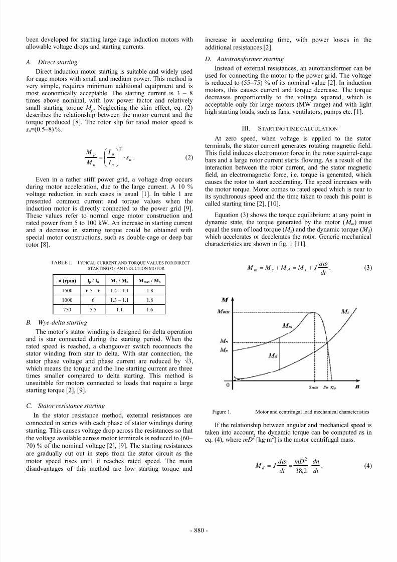
Fig.3 depicts the torque-speed curves of the Končar 5AZ100LB-8 motor and the fan, whereas fig.4 shows the torquespeed of the Sever ZK 100 Ld-8 and the fan. The torque-speedcurve of the fan was derived from its technical specification.Knowing that the torque-speed curve of an axial fan iscentrifugal i.e. the torque is proportional with the speedsquared, the torque can be represented with the followingequation:
2
⎟⎟
⎠
⎞⎜⎜
⎝
⎛ ⋅=
n
sns
n
n M M . (15)
nn [min-1] is the fan’s nominal speed, and Msn [Nm] is thefan’s nominal torque which can be calculated as:
n
insn
n
P M ⋅= 55.9 . (16)
Pin [W] is the fan’s input power, or the power required bythe motor at the shaft. The fan’s nominal speed and input power are taken from its technical specification.
TABLE II. TECHNICAL SPECIFICATIONS OF THE FAN [13]
FanKončar VAAZ A 800-A
L260L720 M100B14P0,9
Air flow [m3/s] 5.7
Total pressure [Pa] 191
Speed [min-1] 720
Input power [kW] 1.05
Static pressure [Pa] 114
ηe [%] 61.9
8/18/2019 Calculation of Induction Motor Starting parameters Using Matlab
http://slidepdf.com/reader/full/calculation-of-induction-motor-starting-parameters-using-matlab 5/6
- 883 -
TABLE III. TECHNICAL SPECIFICATIONS OF THE ANALYSED MOTORS [11],[12]
MotorPn
[kW]
nn
[min-1]
n0
[min-1][%] cosϕ
Un
[V]
In
[A]Ip/In
Mn
[Nm]Mp/Mn Mk /Mn Jm[kgm2]
m
[kg]
Winding
insulation class
Končar 5AZ100LB-8
1.1 700 750 73 0.62 400 3.5 3.7 15 2.1 2.4 0.0104248 23 F
Sever ZK 100Ld-8
1.1 680 750 73 0.72 380 3.2 3.5 15.5 2 2.2 0.0127 34.6 F
Figure 3. Torque-speed curves of the Končar 5AZ 100LB-8 motor andKončar VAAZ A 800-A L260L720 M100B14P0,9 fan. M k =36.01 [Nm];
n0=750 [min-1]
Figure 4. Torque-speed curves of the Sever ZK 100 Ld-8 motor and KončarVAAZ A 800-A L260L720 M100B14P0,9 fan. M k =33.98 [Nm]; n0=750
[min-1]
A. Starting time calculation
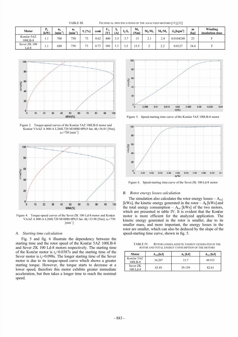
Fig. 5 and fig. 6 illustrate the dependency between thestarting time and the rotor speed of the Končar 5AZ 100LB-8and Sever ZK 100 Ld-8 motors respectively. The starting timeof the Končar motor is t p=0.0387s and the starting time of theSever motor is t p=0.098s. The longer starting time of the Severmotor is due to its torque-speed curve which shows a greaterstarting torque. However, the torque starts to decrease at alower speed, therefore this motor exhibits greater immediateacceleration, but then takes a longer time to reach the nominalspeed.
Figure 5. Speed-starting time curve of the Konč
ar 5AZ 100LB-8 motor
Figure 6. Speed-starting time curve of the Sever ZK 100 Ld-8 motor
B. Rotor energy losses calculation
The simulation also calculates the rotor energy losses – Acu2
[kWs], the kinetic energy generated in the rotor – Ak [kWs] andthe total energy consumption – Arot [kWs] of the two motors,which are presented in table IV. It is evident that the Končarmotor is more efficient for the analyzed application. Thekinetic energy generated in the rotor is smaller, due to itssmaller mass, and more important, the energy losses in therotor are smaller, which can also be deduced by the slope of thespeed-starting time curve, shown in fig. 5.
TABLE IV. R OTOR LOSSES, KINETIC ENERGY GENERATED IN THEROTOR AND TOTAL ENERGY CONSUMPTION OF THE MOTORS
Motor Acu2[kJ] Ak [kJ] Arot [kJ]
Končar 5AZ100LB-8
34.207 15.7 49.915
Sever ZK100 Ld-8
43.45 39.159 82.61
8/18/2019 Calculation of Induction Motor Starting parameters Using Matlab
http://slidepdf.com/reader/full/calculation-of-induction-motor-starting-parameters-using-matlab 6/6
- 884 -
C. Winding temeperature calculation
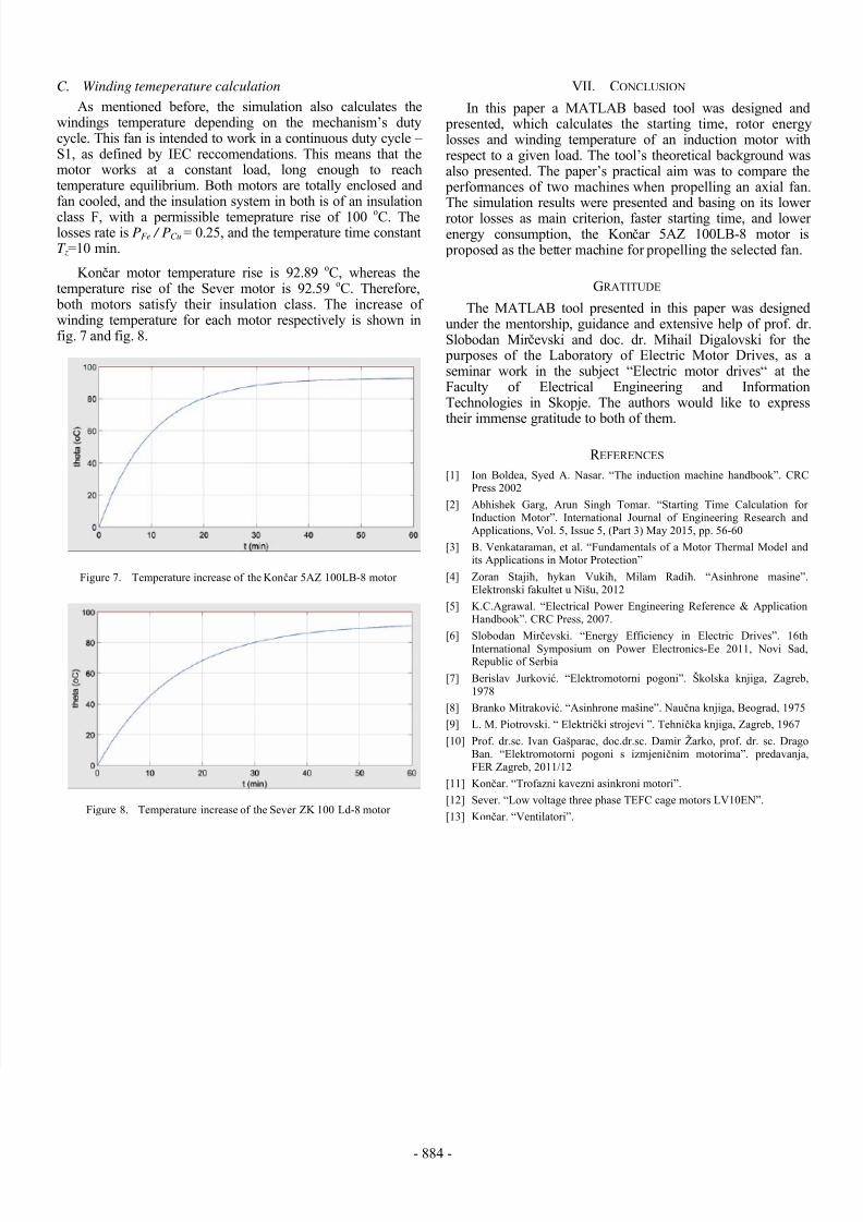
As mentioned before, the simulation also calculates thewindings temperature depending on the mechanism’s dutycycle. This fan is intended to work in a continuous duty cycle –S1, as defined by IEC reccomendations. This means that themotor works at a constant load, long enough to reachtemperature equilibrium. Both motors are totally enclosed andfan cooled, and the insulation system in both is of an insulation
class F, with a permissible temeprature rise of 100 oC. Thelosses rate is PFe / PCu = 0.25, and the temperature time constantT z=10 min.
Končar motor temperature rise is 92.89 oC, whereas thetemperature rise of the Sever motor is 92.59 oC. Therefore, both motors satisfy their insulation class. The increase ofwinding temperature for each motor respectively is shown infig. 7 and fig. 8.
Figure 7. Temperature increase of the Končar 5AZ 100LB-8 motor
Figure 8. Temperature increase of the Sever ZK 100 Ld-8 motor
VII. CONCLUSION
In this paper a MATLAB based tool was designed and presented, which calculates the starting time, rotor energylosses and winding temperature of an induction motor withrespect to a given load. The tool’s theoretical background wasalso presented. The paper’s practical aim was to compare the performances of two machines when propelling an axial fan.The simulation results were presented and basing on its lowerrotor losses as main criterion, faster starting time, and lowerenergy consumption, the Končar 5AZ 100LB-8 motor is proposed as the better machine for propelling the selected fan.
GRATITUDE
The MATLAB tool presented in this paper was designedunder the mentorship, guidance and extensive help of prof. dr.Slobodan Mir čevski and doc. dr. Mihail Digalovski for the purposes of the Laboratory of Electric Motor Drives, as aseminar work in the subject “Electric motor drives“ at theFaculty of Electrical Engineering and InformationTechnologies in Skopje. The authors would like to expresstheir immense gratitude to both of them.
R EFERENCES [1] Ion Boldea, Syed A. Nasar. “The induction machine handbook”. CRC
Press 2002
[2]
Abhishek Garg, Arun Singh Tomar. “Starting Time Calculation forInduction Motor”. International Journal of Engineering Research andApplications, Vol. 5, Issue 5, (Part 3) May 2015, pp. 56-60
[3]
B. Venkataraman, et al. “Fundamentals of a Motor Thermal Model andits Applications in Motor Protection”
[4] Zoran Stajiħ, ħykan Vukiħ, Milam Radiħ. “Asinhrone masine”.Elektronski fakultet u Nišu, 2012
[5]
K.C.Agrawal. “Electrical Power Engineering Reference & ApplicationHandbook”. CRC Press, 2007.
[6]
Slobodan Mir čevski. “Energy Efficiency in Electric Drives”. 16thInternational Symposium on Power Electronics-Ee 2011, Novi Sad,Republic of Serbia
[7]
Berislav Jurković. “Elektromotorni pogoni”. Školska knjiga, Zagreb,1978
[8]
Branko Mitraković. “Asinhrone mašine”. Naučna knjiga, Beograd, 1975
[9] L. M. Piotrovski. “ Električki strojevi ”. Tehnička knjiga, Zagreb, 1967
[10] Prof. dr.sc. Ivan Gašparac, doc.dr.sc. Damir Žarko, prof. dr. sc. DragoBan. “Elektromotorni pogoni s izmjeničnim motorima”. predavanja,FER Zagreb, 2011/12
[11] Končar. “Trofazni kavezni asinkroni motori”.
[12] Sever. “Low voltage three phase TEFC cage motors LV10EN”.
[13] Končar. “Ventilatori”.