calculation of head scatter factors at isocenter or at center of field for any arbitrary jaw setting
TRANSCRIPT

Calculation of head scatter factors at isocenter or at center of field for any arbitrary jawsettingRompin Shih, X. Allen Li, James C. H. Chu, and Wen-Lin Hsu Citation: Medical Physics 26, 506 (1999); doi: 10.1118/1.598549 View online: http://dx.doi.org/10.1118/1.598549 View Table of Contents: http://scitation.aip.org/content/aapm/journal/medphys/26/4?ver=pdfcov Published by the American Association of Physicists in Medicine Articles you may be interested in A three-source model for the calculation of head scatter factors Med. Phys. 29, 2024 (2002); 10.1118/1.1500767 Response to “Comment on ‘The effect of electron contamination on scatter correction factors for photon beamdosimetry’” [Med. Phys. 27, 616 (2000)] Med. Phys. 27, 617 (2000); 10.1118/1.598901 Peak scatter factors for high energy photon beams Med. Phys. 26, 962 (1999); 10.1118/1.598489 Measurements of head-scatter factors with cylindrical build-up caps and columnar miniphantoms Med. Phys. 26, 512 (1999); 10.1118/1.598550 An equivalent square field formula for determining head scatter factors of rectangular fields Med. Phys. 24, 1770 (1997); 10.1118/1.597963
Calculation of head scatter factors at isocenter or at center of fieldfor any arbitrary jaw setting
Rompin Shiha)
Department of Medical Physics, Rush-Presbyterian—St. Luke’s Medical Center,1653 West Congress Parkway, Chicago, Illinois 60612, and Department of Radiation Oncology,Tri-Service General Hospital and National Defense Medical Center, Taipei, Taiwan, R.O.C.
X. Allen Lib) and James C. H. ChuDepartment of Medical Physics, Rush-Presbyterian—St. Luke’s Medical Center,1653 West Congress Parkway, Chicago, Illinois 60612
Wen-Lin HsuDepartment of Radiation Oncology, Tri-Service General Hospital and National Defense Medical Center,Taipei, Taiwan, R.O.C.
~Received 9 September 1998; accepted for publication 26 January 1999!
The purpose of this work is to calculate the head scatter factors for any arbitrary jaw setting byusing two different semi-empirical methods. The head scatter factor at the center of field~COF! forany arbitrary jaw setting can be defined asHCOF(X1 ,X2 ,Y1 ,Y2 ,r )5DCOF
air (X1 ,X2 ,Y1 ,Y2 ,r )/@Dair(5,5,5,5,0)* OAR(r )#, whereX1 , X2 , Y1 , and Y2 are the jaw positions;r is the distancebetween COF and isocenter~IC!; OAR(r ) is the Off-Axis-Ratio;DCOF
air (X1 ,X2 ,Y1 ,Y2 ,r ) is thedose in air measured at COF;Dair(5,5,5,5,0) is the dose in air measured at IC for the 10310 cm2 field. In certain clinical situations, doses are prescribed at IC instead of COF for asym-metric fields. In these cases, head scatter factors should be determined at IC. It is found that thehead scatter factors at IC for asymmetric fields@H IC(X1 ,X2 ,Y1 ,Y2)# are lower thanHCOF(X1 ,X2 ,Y1 ,Y2 ,r ) for the same jaw setting by up to 4%. The values ofH IC(X1 ,X2 ,Y1 ,Y2)and HCOF(X1 ,X2 ,Y1 ,Y2 ,r ) for a variety of jaw settings were measured using a miniphantom of3-cm diameter for a 6- and a 18-MV photon beams. An equivalent square formula, derived pres-ently at the source plane for any jaw setting, was used to calculateHCOF(X1 ,X2 ,Y1 ,Y2 ,r ). Thecalculation and the measurement agree within61% ~60.5% for most clinical situations!. Tocalculate H IC(X1 ,X2 ,Y1 ,Y2), we have generalized the Day’s ‘‘quarter-field’’ method,i.e., H IC(X1 ,X2 ,Y1 ,Y2)5@H(X1 ,X1 ,Y1 ,Y1)1H(X1 ,X1 ,Y2 ,Y2)1H(X2 ,X2 ,Y1 ,Y1)1H(X2 ,X2 ,Y2 ,Y2)]/4. We found that the calculation and the measurement agree within60.8% for the beamsstudied. © 1999 American Association of Physicists in Medicine.@S0094-2405~99!00804-4#
Key words: head scatter factor, asymmetric fields, miniphantom measurement, photon calculation
I. INTRODUCTION
For high-energy photon beam dose calculation, the total scat-ter factor is usually separated into a head scatter factor~H!and a phantom scatter factor.1–5 The head scatter factor~orcollimator scatter factor! is introduced to account for thechange in scattered radiation due to collimator setting and ismeasured by using an ionization chamber with a build-upcap1,4,6,7 or using a beam-coaxial narrow cylindricalphantom.8,9 The value ofH is a function of independent jawsetting and is usually measured at the isocenter~IC! ~i.e., thecollimator rotation axis!. To reduce the number of measure-ments, equivalent-square-field methods have been exploredto calculate the head scatter factors for rectangularfields.10–15 However, the accuracy of these calculations isinfluenced by the effects of field elongation16–18and collima-tor exchange.12 For example, the area-to-perimeter ratio for-mula proposed by Sterlinget al.10 and the equivalent fieldtable reported by Day and Aird11 are used to account for the
elongation effect. Several empirical formulae12–15 which in-clude the both effects have been reported previously for sym-metric rectangular fields.
For asymmetric fields, the head scatter factor has so farbeen measured at the center of field~COF! with the off-center effect removed.19,20 The values ofH for single direc-tion asymmetric fields measured at COF have been studiedby Khanet al.19 Cadman20 extended the Khanet al.’s inves-tigation to the dual asymmetric fields. Both studies show thatthe head scatter factor of an asymmetric field at COF is ap-proximately equal to the correspondingH value measured atIC for the symmetric field with the same field dimension.
The intention of this study is to propose methods to cal-culate the head scatter factors for any arbitrary jaw settingusing theH values of square fields. Kimet al.14 have pro-posed a field mapping method to calculate equivalent squareswhich can predict theH values for symmetric rectangularfields to within61%. One of our purposes, here, is to extendtheir method to calculate the head scatter factor at COF for
506 506Med. Phys. 26 „4…, April 1999 0094-2405/99/26 „4…/506/6/$15.00 © 1999 Am. Assoc. Phys. Med.
any arbitrary fields~including asymmetric jaw settings!. Incertain clinical situations, doses are prescribed at IC insteadof COF for asymmetric fields. In these cases, the head scatterfactor should be determined at IC. Rosenberget al.21 haverecently used the Day’s22 ‘‘quarter-field’’ method to calcu-late the dose in phantom for asymmetric fields. Their calcu-lations and the measurements agree within61%. Anothergoal of this study is to use this ‘‘quarter-field’’ method tocalculate theH value at IC for an asymmetric field. Thedifferences between theH values at IC and at COF for anasymmetric field will be studied.
II. METHODS AND MATERIALS
For an independent jaw setting of (X1 ,X2 ,Y1 ,Y2), thehead scatter factor may be determined at COF or at IC~Fig.1!. The value ofHCOF can be measured by:19,20
HCOF~X1 ,X2 ,Y1 ,Y2 ,r !5DCOF
air ~X1 ,X2 ,Y1 ,Y2 ,r !
Dair~5,5,5,5,0!* OAR~r !, ~1!
wherer is the distance between COF and IC; OAR(r ) is theOff-Axis-Ratio measured in air;DCOF
air (X1 ,X2 ,Y1 ,Y2 ,r ) isthe dose in air measured at COF;Dair(5,5,5,5,0) is the dosein air measured at IC for the 10310 cm2 field. The headscatter factors at IC~i.e., the collimator rotation axis! may bedetermined by:
H IC~X1 ,X2 ,Y1 ,Y2!5D IC
air~X1 ,X2 ,Y1 ,Y2!
Dair~5,5,5,5!, ~2!
whereD ICair(X1 ,X2 ,Y1 ,Y2) is the dose in air measured at IC.
Jaffrayet al.23 have suggested that the head scatter radia-tions are mainly contributed by the extrafocal radiation fromthe flattening filter. Kimet al.,15 Ahnesjo,24 and Lamet al.25
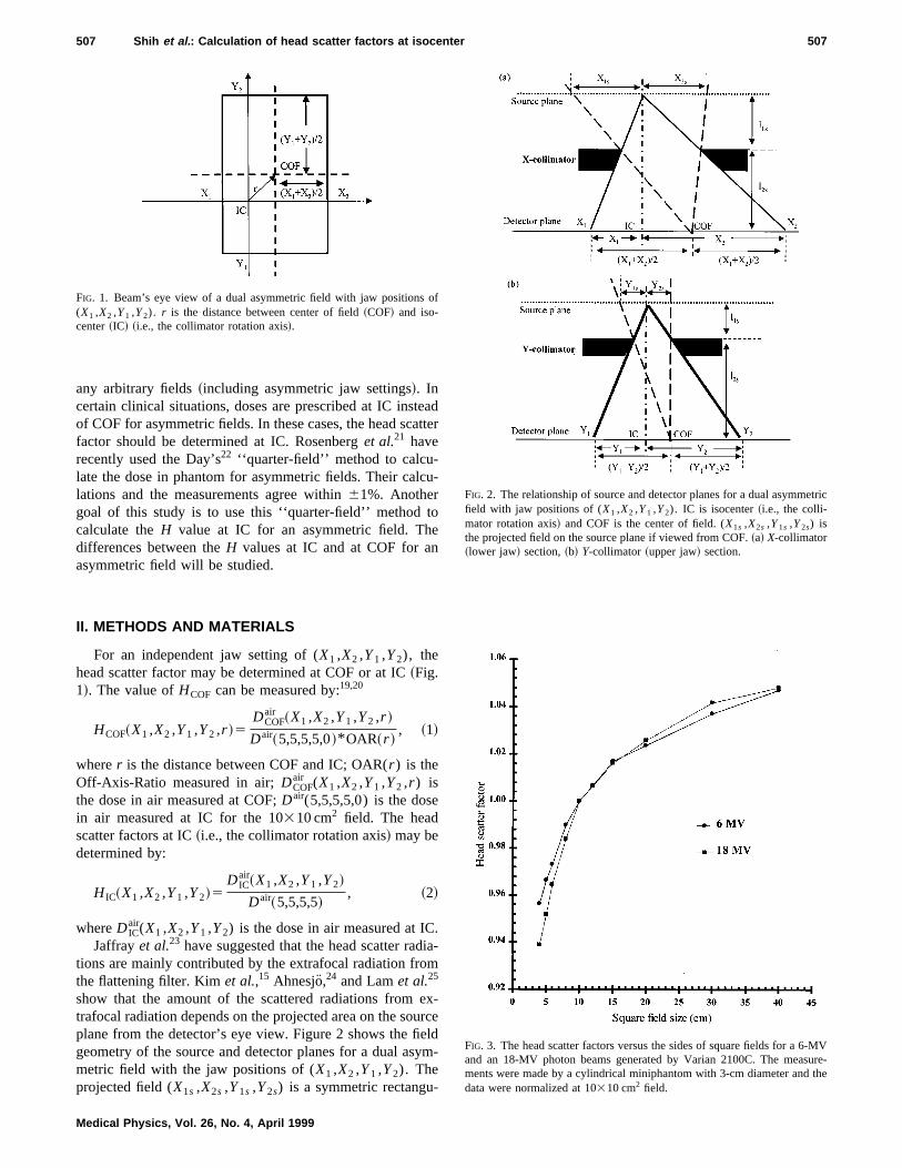
show that the amount of the scattered radiations from ex-trafocal radiation depends on the projected area on the sourceplane from the detector’s eye view. Figure 2 shows the fieldgeometry of the source and detector planes for a dual asym-metric field with the jaw positions of (X1 ,X2 ,Y1 ,Y2). Theprojected field (X1s ,X2s ,Y1s ,Y2s) is a symmetric rectangu-
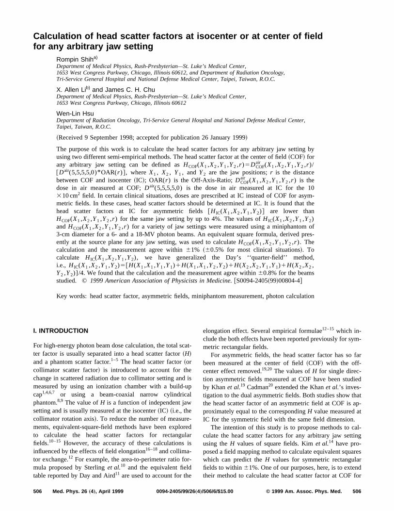
FIG. 1. Beam’s eye view of a dual asymmetric field with jaw positions of(X1 ,X2 ,Y1 ,Y2). r is the distance between center of field~COF! and iso-center~IC! ~i.e., the collimator rotation axis!.
FIG. 2. The relationship of source and detector planes for a dual asymmetricfield with jaw positions of (X1 ,X2 ,Y1 ,Y2). IC is isocenter~i.e., the colli-mator rotation axis! and COF is the center of field. (X1s ,X2s ,Y1s ,Y2s) isthe projected field on the source plane if viewed from COF.~a! X-collimator~lower jaw! section,~b! Y-collimator ~upper jaw! section.
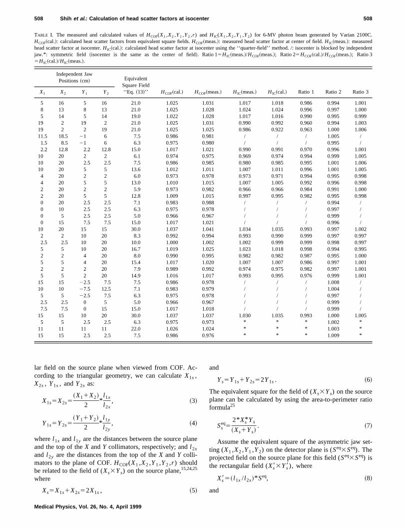
FIG. 3. The head scatter factors versus the sides of square fields for a 6-MVand an 18-MV photon beams generated by Varian 2100C. The measure-ments were made by a cylindrical miniphantom with 3-cm diameter and thedata were normalized at 10310 cm2 field.
507 Shih et al. : Calculation of head scatter factors at isocenter 507
Medical Physics, Vol. 26, No. 4, April 1999
lar field on the source plane when viewed from COF. Ac-cording to the triangular geometry, we can calculateX1s ,X2s , Y1s , andY2s as:
X1s5X2s5~X11X2!
2*
l 1x
l 2x, ~3!
Y1s5Y2s5~Y11Y2!
2*
l 1y
l 2y, ~4!
wherel 1x and l 1y are the distances between the source planeand the top of theX andY collimators, respectively; andl 2x
and l 2y are the distances from the top of theX andY colli-mators to the plane of COF.HCOF(X1 ,X2 ,Y1 ,Y2 ,r ) shouldbe related to the field of (Xs3Ys) on the source plane,15,24,25
where
Xs5X1s1X2s52X1s , ~5!
and
Ys5Y1s1Y2s52Y1s . ~6!
The equivalent square for the field of (Xs3Ys) on the sourceplane can be calculated by using the area-to-perimeter ratioformula25
Sseq5
2* Xs* Ys
~Xs1Ys!. ~7!
Assume the equivalent square of the asymmetric jaw set-ting (X1 ,X2 ,Y1 ,Y2) on the detector plane is (Seq3Seq). Theprojected field on the source plane for this field (Seq3Seq) isthe rectangular field (Xs83Ys8), where
Xs85~ l 1x / l 2x!* Seq, ~8!
and
TABLE I. The measured and calculated values ofHCOF(X1 ,X2 ,Y1 ,Y2 ,r ) and H IC(X1 ,X2 ,Y1 ,Y2) for 6-MV photon beam generated by Varian 2100C.HCOF~cal.!: calculated heat scatter factors from equivalent square fields.HCOF~meas.!: measured head scatter factor at center of field.H IC~meas.!: measuredhead scatter factor at isocenter.H IC~cal.!: calculated head scatter factor at isocenter using the ‘‘quarter-field’’ method. /: isocenter is blocked by independentjaw.* : symmetric field ~isocenter is the same as the center of field!. Ratio 15H IC~meas.!/HCOF~meas.!; Ratio 25HCOF~cal.!/HCOF~meas.!; Ratio 35H IC~cal.!/H IC~meas.!.
Independent JawPositions~cm! Equivalent
Square Field‘‘Eq. ~13!’’ HCOF~cal.! HCOF~meas.! H IC~meas.! H IC~cal.! Ratio 1 Ratio 2 Ratio 3X1 X2 Y1 Y2
5 16 5 16 21.0 1.025 1.031 1.017 1.018 0.986 0.994 1.0018 13 8 13 21.0 1.025 1.028 1.024 1.024 0.996 0.997 1.0005 14 5 14 19.0 1.022 1.028 1.017 1.016 0.990 0.995 0.999
19 2 19 2 21.0 1.025 1.031 0.990 0.992 0.960 0.994 1.00319 2 2 19 21.0 1.025 1.025 0.986 0.922 0.963 1.000 1.00611.5 18.5 21 6 7.5 0.986 0.981 / / / 1.005 /1.5 8.5 21 6 6.3 0.975 0.980 / / / 0.995 /2.2 12.8 2.2 12.8 15.0 1.017 1.021 0.990 0.991 0.970 0.996 1.001
10 20 2 2 6.1 0.974 0.975 0.969 0.974 0.994 0.999 1.00510 20 2.5 2.5 7.5 0.986 0.985 0.980 0.985 0.995 1.001 1.00610 20 5 5 13.6 1.012 1.011 1.007 1.011 0.996 1.001 1.0054 20 2 2 6.0 0.973 0.978 0.973 0.971 0.994 0.995 0.9984 20 5 5 13.0 1.010 1.015 1.007 1.005 0.992 0.996 0.9982 20 2 2 5.9 0.973 0.982 0.966 0.966 0.984 0.991 1.0002 20 5 5 12.8 1.009 1.015 0.997 0.995 0.982 0.995 0.9980 20 2.5 2.5 7.1 0.983 0.988 / / / 0.994 /0 10 2.5 2.5 6.3 0.975 0.978 / / / 0.997 /0 5 2.5 2.5 5.0 0.966 0.967 / / / 0.999 /0 15 7.5 7.5 15.0 1.017 1.021 / / / 0.996 /
10 20 15 15 30.0 1.037 1.041 1.034 1.035 0.993 0.997 1.0022 2 10 20 8.3 0.992 0.994 0.993 0.990 0.999 0.997 0.9972.5 2.5 10 20 10.0 1.000 1.002 1.002 0.999 0.999 0.998 0.9975 5 10 20 16.7 1.019 1.025 1.023 1.018 0.998 0.994 0.9952 2 4 20 8.0 0.990 0.995 0.982 0.982 0.987 0.995 1.0005 5 4 20 15.4 1.017 1.020 1.007 1.007 0.986 0.997 1.0012 2 2 20 7.9 0.989 0.992 0.974 0.975 0.982 0.997 1.0015 5 2 20 14.9 1.016 1.017 0.993 0.995 0.976 0.999 1.001
15 15 22.5 7.5 7.5 0.986 0.978 / / / 1.008 /10 10 27.5 12.5 7.1 0.983 0.979 / / / 1.004 /5 5 22.5 7.5 6.3 0.975 0.978 / / / 0.997 /2.5 2.5 0 5 5.0 0.966 0.967 / / / 0.999 /7.5 7.5 0 15 15.0 1.017 1.018 / / / 0.999 /
15 15 10 20 30.0 1.037 1.037 1.030 1.035 0.993 1.000 1.0055 5 2.5 2.5 6.3 0.975 0.973 * * * 1.002 *
11 11 11 11 22.0 1.026 1.024 * * * 1.003 *15 15 2.5 2.5 7.5 0.986 0.976 * * * 1.009 *
508 Shih et al. : Calculation of head scatter factors at isocenter 508
Medical Physics, Vol. 26, No. 4, April 1999
Ys85~ l 1y / l 2y!* Seq. ~9!
On the source plane, the side of equivalent square for thisrectangular field (Xs83Ys8) is Ss
eq, which can be calculatedas:
Sseq5
2* Xs8* Ys8
~Xs81Ys8!. ~10!
Substituting Eq.~8! and Eq.~9! into Eq. ~10!, we have
Sseq5
2* ~ l 1x / l 2x!* Seq* ~ l 1y / l 2y!* Seq
~ l 1x / l 2x!* Seq1~ l 1y / l 2y!* Seq . ~11!
From Eqs.~7! and ~11!, we arrive at
Seq5@~ l 1x / l 2x!1~ l 1y / l 2y!#* Xs* Ys
~ l 1x / l 2x!* ~ l 1y / l 2y!* ~Xs1Ys!. ~12!
By combining Eqs.~3!, ~4!, ~5!, ~6!, and~12!, the equivalentsquare (Seq3Seq) for the asymmetric jaw setting of(X1 ,X2 ,Y1 ,Y2) can be obtained as
Seq5~ l 1k!* ~X11X2!* ~Y11Y2!
k* ~X11X2!1~Y11Y2!, ~13!
wherek5@( l 1x / l 2x)#/@( l 1y / l 2y)#.Equation ~13! can be used to calculate the equivalent
square for any arbitrary jaw setting~including symmetric andasymmetric fields!. Note that, for a symmetric field, our Eq.~13! becomes the Eq.~9! of Kim et al.14 Thus one need onlythe head scatter factors of square fields to calculateHCOF(X1 ,X2 ,Y1 ,Y2 ,r ) through
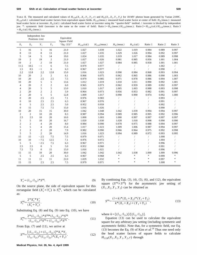
TABLE II. The measured and calculated values ofHCOF(X1 ,X2 ,Y1 ,Y2 ,r ) and H IC(X1 ,X2 ,Y1 ,Y2) for 18-MV photon beam generated by Varian 2100C.HCOF~cal.!: calculated head scatter factors from equivalent square fields.HCOF~meas.!: measured head scatter factor at center of field.H IC~meas.!: measuredhead scatter factor at isocenter.H IC~cal.!: calculated head scatter factor at isocenter using the ‘‘quarter-field’’ method. /: isocenter is blocked by independentjaw. * : symmetric field ~isocenter is the same as the center of field!. Ratio 15H IC~meas.!/HCOF~meas.!; Ratio 25HCOF~cal.!/HCOF~meas.!; Ratio 35H IC~cal.!/H IC~meas.!.
Independent JawPositions~cm! Equivalent
Square Field‘‘Eq. ~13!’’ HCOF~cal.! HCOF~meas.! H IC~meas.! H IC~cal.! Ratio 1 Ratio 2 Ratio 3X1 X2 Y1 Y2
5 16 5 16 21.0 1.027 1.039 1.022 1.019 0.984 0.989 0.9978 13 8 13 21.0 1.027 1.035 1.029 1.026 0.994 0.992 0.9975 14 5 14 19.0 1.024 1.035 1.019 1.017 0.984 0.989 0.998
19 2 19 2 21.0 1.027 1.026 0.981 0.985 0.956 1.001 1.00419 2 2 19 21.0 1.027 1.027 0.984 0.985 0.958 1.001 1.00111.5 18.5 21 6 7.5 0.979 0.977 / / / 1.002 /1.5 8.5 21 6 6.3 0.967 0.977 / / / 0.990 /2.2 12.8 2.2 12.8 15.0 1.016 1.023 0.990 0.984 0.968 0.993 0.994
10 20 2 2 6.1 0.966 0.975 0.962 0.965 0.986 0.990 1.00310 20 2.5 2.5 7.5 0.979 0.985 0.971 0.978 0.986 0.994 1.00710 20 5 5 13.6 1.012 1.019 1.010 1.011 0.990 0.992 1.0014 20 2 2 6.0 0.965 0.973 0.962 0.959 0.989 0.992 0.9974 20 5 5 13.0 1.010 1.017 1.005 1.003 0.988 0.993 0.9982 20 2 2 5.9 0.964 0.973 0.956 0.953 0.982 0.991 0.9972 20 5 5 12.8 1.009 1.017 0.990 0.990 0.974 0.992 1.0000 20 2.5 2.5 7.1 0.976 0.983 / / / 0.993 /0 10 2.5 2.5 6.3 0.967 0.976 / / / 0.991 /0 5 2.5 2.5 5.0 0.952 0.959 / / / 0.992 /0 15 7.5 7.5 15.0 1.016 1.026 / / / 0.990 /
10 20 15 15 30.0 1.042 1.048 1.042 1.039 0.994 0.994 0.9972 2 10 20 8.3 0.987 0.994 0.989 0.985 0.995 0.992 0.9962.5 2.5 10 20 10.0 1.000 1.003 1.000 0.997 0.997 0.997 0.9975 5 10 20 16.7 1.020 1.030 1.028 1.018 0.998 0.990 0.9902 2 4 20 8.0 0.984 0.990 0.978 0.975 0.988 0.994 0.9975 5 4 20 15.4 1.017 1.023 1.009 1.006 0.987 0.994 0.9972 2 2 20 7.9 0.982 0.990 0.966 0.964 0.975 0.992 0.9985 5 2 20 14.9 1.016 1.023 0.994 0.989 0.972 0.993 0.995
15 15 22.5 7.5 7.5 0.979 0.971 / / / 1.008 /10 10 27.5 12.5 7.1 0.976 0.972 / / / 1.004 /5 5 22.5 7.5 6.3 0.967 0.971 / / / 0.996 /2.5 2.5 0 5 5.0 0.952 0.960 / / / 0.991 /7.5 7.5 0 15 15.0 1.016 1.021 / / / 0.996 /
15 15 10 20 30.0 1.042 1.042 1.042 1.038 1.000 1.000 0.9965 5 2.5 2.5 6.3 0.967 0.968 * * * 0.999 *
11 11 11 11 22.0 1.029 1.032 * * * 0.997 *15 15 2.5 2.5 7.5 0.979 0.971 * * * 1.008 *
509 Shih et al. : Calculation of head scatter factors at isocenter 509
Medical Physics, Vol. 26, No. 4, April 1999
HCOF~X1 ,X2 ,Y1 ,Y2 ,r !5H~Seq3Seq!. ~14!
It should be noted that the projected area on the sourceplane of an asymmetric jaw setting (X1 ,X2 ,Y1 ,Y2), ifviewed from COF, is equal to that of the symmetric field
with the same dimension. This justifies the observation,made by Khanet al.19 and Cadman,20 that theH values forthese two fields were the same.
For the head scatter factor at IC, we can considerH IC iscontributed from each jaw setting. Thus it may be calculatedbased on the ‘‘quarter-field’’ method via:
H IC~X1 ,X2 ,Y1 ,Y2!5H~X1 ,X1 ,Y1 ,Y1!1H~X1 ,X1 ,Y2 ,Y2!1H~X2 ,X2 ,Y1 ,Y1!1H~X2 ,X2 ,Y2 ,Y2!
4. ~15!
A 6-MV and an 18-MV beam generated by a Varian2100C were studied. We have measuredHCOF(X1 ,X2 ,Y1 ,Y2 ,r ) andH IC(X1 ,X2 ,Y1 ,Y2) using Eq.~1! and Eq.~2!,respectively, for a variety of jaw settings~including bothsymmetric and asymmetric fields!. A 0.125-cm3 PTW Snackchamber situated at 5-cm depth in a cylindrical polystyreneminiphantom was used for the measurements. The diameterof miniphantom is 3 cm. The effects of lateral electron dis-equilibrium and electron contamination with such a miniph-antom are not significant as reported by Liet al.26 Theminiphantom was placed on the top of 15-cm-thick styro-foam to prevent backscatters from the treatment couch. Thedistance between source and detector planes is 100 cm. Thehead scatter factors for square fields from 434 cm2 to 40340 cm2 are also measured for both energies. The values ofHCOF andH IC for all the measurement jaw settings are thencalculated based on Eq.~14! and Eq.~15!, respectively, usingthe data of the square fields, and are also compared with themeasurements.
III. RESULT
Figure 3 shows the head scatter factors measured forsquare fields for the 6-MV and the 18-MV photon beams.The calculated values ofHCOF(X1 ,X2 ,Y1 ,Y2 ,r ) andH IC(X1 ,X2 ,Y1 ,Y2) were obtained from Eq.~14! and Eq.~15!, respectively, using the square-field data of Fig. 3. Theboth measured and calculated values ofHCOF and H IC forsome representative jaw settings are tabulated in Table I andTable II for the 6- and 18-MV beams, respectively. Theequivalent square-field size calculated by Eq.~13!, the ratiosof the measured values ofH IC and HCOF@H IC(med.)/HCOF(med.)#, the calculated and measured values ofHCOF
@HCOF(cal.)/HCOF(med.)#, and the calculated measured val-ues ofH IC @H IC(cal.)/H IC(med.)# are also included in TableI and Table II.
It is seen from Table I and Table II that~a! the calculatedhead scatter factors at COF are consistent with the measure-ments to within61.0%, for both energies;~b! the values ofcalculated and measured head scatter factors at IC agreewithin 60.8%;~c! the head scatter factors measured at IC arelower than those measured at COF by up to 4% for thebeams studied.
IV. CONCLUSION
This study has shown that the head scatter factors for anyarbitrary jaw setting can be calculated from the head scatterfactors of the square fields. Thus in the clinic, one only needto measure theH values for square fields. TheH values atCOF and at IC can be calculated by Eq.~14! and Eq.~15!using the square-field data. The calculations are found toagree with the measurements to within61.0%. For an asym-metric field,H IC is lower thanHCOF by up to 4%~1–3% formost clinical situations!.
a!Electronic mail: [email protected]!Electronic mail: [email protected]. M. Khan, W. Sewchand, J. Lee, and J. F. Williamson, ‘‘Revision oftissue-maximum ratio and scatter-maximum ratio concepts for cobalt 60and higher energy x-ray beams,’’ Med. Phys.7, 230–237~1980!.
2M. S. Patterson and P. C. Shragge, ‘‘Characteristics of an 18 MV photonbean from a Therac 20 medical linear accelerator,’’ Med. Phys.8, 312–318 ~1981!.
3G. Luxton and M. A. Astrahan, ‘‘Output factor constituents of a high-energy photon beam,’’ Med. Phys.15, 88–91~1988!.
4J. Spicka, D. Herron, and C. Orton, ‘‘Separating output factor into colli-mator and phantom scatter factor for megavoltage photon calculations,’’Med. Dos.13, 23–24~1988!.
5B. E. Bjarngard, ‘‘Scatter factors for a 25-MV x-ray beam,’’ Med. Phys.20, 357–361~1993!.
6K. R. Kase and G. K. Svensson, ‘‘Head scatter data for several linearaccelerators~4–18 MV!,’’ Med. Phys.13, 530–532~1986!.
7T. C. Zhu and B. E. Bja¨rngard, ‘‘The head-scatter factor for small fieldsizes,’’ Med. Phys.21, 65–68~1994!.
8J. J. M. van Gasteren, S. Heukelom, H. J. van Kleffens, R. van der Laarse,J. L. M. Venselaar, and C. F. Wesermann, ‘‘The determination of phan-tom and collimator scatter components of the output of megavoltage pho-ton beams: measurement of the collimator scatter part with a beam-coaxial narrow cylindrical phantom,’’ Radiother. Oncol.20, 250–257~1991!.
9M. Tatcher and B. E. Bja¨rngard, ‘‘Head-scatter factors in rectangularphoton fields,’’ Med. Phys.20, 205–206~1993!.
10T. D. Sterling, H. Perry, and L. Katz, ‘‘Automation of radiation treatmentplanning,’’ Br. J. Radiol.37, 544–550~1964!.
11M. J. Day and E. G. A. Aird, ‘‘The equivalent field method for dosedetermination in rectangular fields,’’ Br. J. Radiol.17, 105–114~1983!.
12P. Vadash and B. Bja¨rngard, ‘‘An equivalent square formula for headscatter factors,’’ Med. Phys.20, 733–734~1993!.
13M. K. Yu, B. Murray, and R. Sloboda, ‘‘Parametrization of head scatterfactors for rectangular photon fields using an equivalent square formal-ism,’’ Med. Phys.22, 1329–1332~1995!.
14S. Kim, T. C. Zhu, and J. R. Palta, ‘‘An equivalent square field formulafor determining head scatter factors of rectangular fields,’’ Med. Phys.24,1770–1774~1997!.
15S. Kim, J. R. Palta, and T. C. Zhu, ‘‘The equivalent square concept for the
510 Shih et al. : Calculation of head scatter factors at isocenter 510
Medical Physics, Vol. 26, No. 4, April 1999
head scatter factor based on scatter from flattening filter,’’ Phys. Med.Biol. 43, 1593–1604~1998!.
16D. J. Dawson, ‘‘Elongation effects on the Therac 6 linear accelerator,’’Med. Phys.5, 439–442~1978!.
17R. F. Moyer, ‘‘Systematic patient-dose errors for 4- and 10-MeV micro-wave linear accelerators associated with rectangular collimator settings,’’Radiology129, 803–806~1978!.
18P. D. Higgins, W. H. Sohn, C. H. Sibata, and W. A. McCarthy, ‘‘Scatterfactor corrections for elongated fields,’’ Med. Phys.16, 800–802~1989!.
19F. M. Khan, B. J. Gerbi, and F. C. Deibel, ‘‘Dosimetry of asymmetricx-ray collimators,’’ Med. Phys.13, 936–941~1986!.
20P. Cadman, ‘‘A dosimetric investigation of scatter conditions for dualasymmetric collimators in open fields,’’ Med. Phys.22, 457–463~1995!.
21I. Rosenberg, J. C. H. Chu, and V. Saxena, ‘‘Calculation of monitor unitsfor a linear accelerator with asymmetric jaws,’’ Med. Phys.22, 55–61~1995!.
22M. J. Day, ‘‘A note on the calculation of dose in x-ray fields,’’ Br. J.Radiol.23, 368–370~1950!.
23D. A. Jaffray, J. J. Battista, A. Fenster, and P. Munro, ‘‘X-ray sources ofmedical linear accelerators: Focal and extra-focal radiation,’’ Med. Phys.20, 1417–1427~1993!.
24A. Ahnesjo, ‘‘Analytic modeling of photon scatter from flattening filtersin photon therapy beams,’’ Med. Phys.21, 1227–1235~1994!.
25K. L. Lam, M. S. Muthuswamy, and R. K. Ten Haken, ‘‘Flattening-filter-based empirical methods to parametrize the head scatter factor,’’ Med.Phys.23, 343–352~1996!.
26X. A. Li, M. Soubra, J. Szanto, and L. H. Gerig, ‘‘Lateral electron equi-librium and electron contamination in measurements of head-scatter fac-tors using miniphantoms and brass caps,’’ Med. Phys.22, 1167–1170~1995!.
511 Shih et al. : Calculation of head scatter factors at isocenter 511
Medical Physics, Vol. 26, No. 4, April 1999