calculation of coherent emissions and gain from a
TRANSCRIPT
PFC/RR-95-10
Calculation of Coherent Emissions and Gain from a Prebunched Free Electron Laser
Elliott A. Treadwell
August, 1995
Elliott A. Treadwell, Ph. D. Professor of Physics
Chicago State University Chicago, Illinois 60628-1598
Visiting Scientist, 1995 Plasma Fusion Center
Massachusetts Institute of Technology Cambridge, MA 02139
This work was supported by the United States Department of Energy, Office of Fusion Energy grant number DE-AC02-78ET-51013. Reproduction, translation, publication, use, and disposal, in whole or in part, by or for the United States
Government is permitted.
to Venita, Aaron, Leeanna, Megan, Richard Temkin, and the gyrotron-accelerator group at the MIT Plasma Fusion Center for their patience, and assistance during the Summer, 1995.

Contents
I . Introduction and FEL Description (1)
32. Linear Theory of the Prebunched E L ( 3 )
A. Radio Frequency Linac ( 3 )
B. Radiation Field within the Resonator ( 3 )
C. Particle and Wave Dynamics within the Resonator ( 6
LLT. Coherent Emissions in the Single Pass Model ( 7 )
N. Sipzal Gain in the Single Pass Model ( 9 )
V. Application of the Signal Pass Model to the Proposed Prebunched FEL a t M.I.T. ( 11 1
VI. Figures and Plots (13)
WI. References (22 )
ii
I . Introduction and €EL Description
A summary report of my research activities is presented. As a Visiting Scientist at the Plasma Fusion Center of the Massachusetts Institute of Technology, I have explored Free Electron Laser ( FEL ) physics and have found a rich blend of theoretical studies: classical electrodynamics, particle physics analysis of complex variables, special mathematical functions, and microwave circuits. The interdisciplinary approach to FEL physics should bode well for future technology. Future goals should include: a high power source of coherent radiation and an instrument which is tunable in the spectral region of millimeter-wavelengths through the infrared. The idea of tunability is connected to the fact that the rf wavelength scattered by beam electrons, which traverse the resonance cavity, is inversely proportional to the square of the electron energy. Therefore the FEL beam will amphfy an rf wave if it is near synchronism with the beat wave of the rf and the wiggler.
This report advances a theoretical model for the single pass growth of coherent radiation in a prebunched FEL system. The FEL system includes a radio frequency linear accelerator ( rf linac ) as the injector, a resonator cavity with a wiggler magnet, and two highly reflective plano-concave mirrors, typically 99 % of the radiation is reflected inside the resonator. The model is based upon the following assumptions: a) the electron beam is cold, b) a super-electron is a particle with - 108 elementary charges inside a bunch. The bunch length is much smaller than the radiation wavelength and the super-electron scatters with the rf wave in a single pass through the resonator, c) a smooth phase space transition must exist between the rf linac and the resonator, d) the energy gain is low per pass and consequently in the linear gain regime, and e) if condition (b) is satisfied and the bunch is resonant with the FEL beat wave, all electrons lose energy to the wave, in the lowest order approximation.
A simple scaling technique is used to calculate the output power given the number of particles in a bunch and the efficiency for retrieving coherent radiation from the resonator.
1.

The FEL system is illustrated in Figure 1. The process of producing high power, coherent radiation begins with the injector: a rf linac. The rf linac injects prebunched, relativistic electrons into a resonant cavity. Each electron bunch or micropulse has a peak current of -100 A, and is approximately 0.1 ps in pulse width. Consecutive micropulses are separated by Ten thousand equally spaced micropulses form a 1 ps macropulse. The average current over the macropulse is usually much smaller than the peak current in the micropulse, e.g. a typical macropulse current, c I > = 0.250 A .
- 10.0 ps.
The prebunched electron beam exits the rf linac and enters the soft undulating magnetic field of the wiggler. The sinusoidal magnetic field of a few kG perturbs the electron orbit with a wiggle in the horizontal beam plane ( x-z plane ). The pondermotive force accelerates the electron through several meters of undulator periods and periodically the electron is synchronous with the combined rf wave - wiggler field. The synchronism between the electron and FEL beat wave generates coherent radiation. The radiation is emitted within a small bandwidth and builds up in front of the electron. As the beam approaches the end of the wiggler, the electron beam is diverted and the coherent radiation is reflected by an axially oriented mirror. In practice the radiation bounces several hundred times between the mirrors in order for the radiation to gain a few percent. It is noteworthy that a simple scaling rule can be applied to coherent radiation growth from a super- electron-rf wave resonance in the FEL: The output power, from coherent scattering in the resonator, is proportional to the square of the number of charges in the super-electron and the input power, from incoherent scattering in the resonator, is proportional to the number of charges in the electron bun&. If a ratio, P(out)/P(in) is modified by the efficiency for retrieving coherent radiation from the resonator - 10 k W of output power is expected from 0.01 W of input power.
The final section of this report uses parameters from the FEL project the M.I.T. Plasma Fusion Center, to calculate the coherent proposed by
emissions and gain in a single pass.
2.

H. Liaear Theory of the Prebunched FEL
A. Radio Frequency Linac
The rf linac injects small electron micropulses into the FEL resonance cavity. The accelerator utilizes a photocathode RF Gun injector, and a Traveling Wave Relativistic Klystron, which delivers - 20 MW power, 60 dB gain, and an efficiency of - 50 %, at rf frequencies of - 10 GHz. Ejected electron energies are in the range: 10 MeV c E( beam ) e 120 MeV, and accordingly wavelengths are in the range: 100 pm < h c 1000 ym. Note, it is possible to achieve electron energies and wavelengths outside the quoted ranges; however it will not be possible to maintain the cold nondispersive beam that is required in this analysis. Figure 2. is a schematic diagram of an rf linear accelerator. Note, the accelerator has a series of resonant cavities in which an electromagnetic field oscillates. Typically the resonant frequency is of order 1 GHz ( called L- band ) to 3 GHz ( S-band ). The field oscillates in each cavity has an electric field parallel to the axis that is used to accelerate the electrons. As electrons pass from one cavity to another, their arrival is timed to coincide with the maximum amplitude of the electric field in each cavity. The rf power required to strengthen the fields is supplied by an external, high- power, klystron amplifier. The power is distributed from cavity to cavity through interconnections.
B. Radiation Field within the Resonator
There is no radiation produced in the resonator until the beam is present. The presence of these highly relativistic electrons implies that the wiggler magnetic field and rf fields must interact through a vector potential the pondermotive potential:
The vector potential for the radiation field is:
AR(Z,t) = AR{ exp[ i (knz -%t ) ]G+ + e x p [ - i ( k n z - y , t ) I & }
= an(t) sin knz exp [ iot 3 Gz + C. C.
3. . . . (1)

The radiation field within the resonator is represented by the superposition of spatial modes, such that the tangential electric field vanishes at the mirrors. The vector potential or the wiggler field is :
= Aw{ exp[i(kwz ) ] G + + exp[-i(k,z ) ]Z- 1
. I . (2)
where kn = x n / L , an(t) is the Fourier coefficient of the nth spatial mode and c. c. denotes the complex conjugate of the previous imaginary term. The wave number of the wiggler period , kw = 2n / lw is expressed in terms of the length of the wiggler period ( 1 ). See Figure 1. for a schematic diagram of the FEL resonator.
The one-dimensional wave equation for expression in equation (1) :
AR( z,t ) is written using the
J (z,t ) is the driving current density which will become linear in AR( z, t ) . The phenomenological term has the expression v = 0~ / Q , where is the laser frequency and Q is the quality factor associated with the resonator.
The driving current density will have two characteristics : a coherent and an incoherent driving current density :
... (4)
Jc(z , t ) = - I e I vw Fc < n ( z,t ) > , where Fc is the filling factor : cq, / CJR
J h c ( z , t ) = - I e I vwFinc[ n ( z , t ) - < n(z,t) > ] * . . ( 5 )
4.

Where Finc = d ( fm 5 ) , fm is the loss factor due to the finite size of the mirror. The 6 term is given by the expression : E = cq, ( 'yo / YOZ ) 6 ( hLyoz 12
Note, < n ( z,t ) > is the beam density assurning an uncorrelated ensemble of electrons. The model requires the electron density to be discrete and each electron to occupy a sheet of charge, i.e. a given orbit through the resonator cavity. All density fluctuations are minimized in this fashion and each sheet of charge is uncorrelated; thus the model prevents the growth of density fluctuations as the beam traverses the cavity and the Heisenberg Uncertainty Principle is obeyed.
The wiggle velocity is :
VW = C p N = l e lAw(z ) / (yomc) = ~ ~ c o s ( k ~ z ) i ? ~
In order to obtain the equation for the Fourier coefficients of the radiation field, first substitute ( 1 ) together with ( 5 ) into the wave equation ( 3 }. Assume an(t) to be a slowly varying function of time Le., I &(t) / an(t) I i< on then the time derivative of the Fourier coefficients of the radiation are :
Note, in order to evaluate an(t) , knowledge of the axial orbit < z( zoj,t } > is required.
The model continues to unfold as the dynamics of the electron interaction with the FEL beat wave is described. The distinction is drawn between the unperturbed and the perturbed electron orbits .
5.
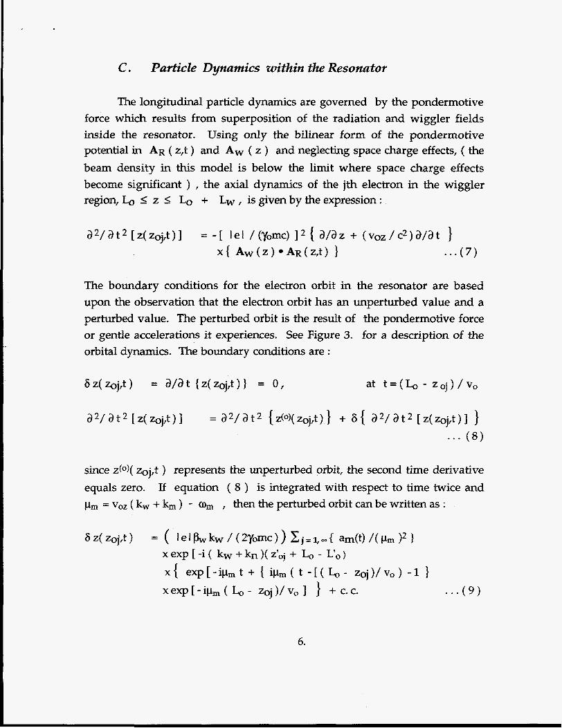
C . Particle Dynamics within the Resonator
The longitudinal particle dynamics are governed by the pondermotive force which results from superposition of the radiation and wiggler fields inside the resonator. Using only the bilinear form of the pondermotive potential in AR ( z,t ) and Aw ( z ) and neglecting space charge effects, ( the beam density in this model is below the limit where space charge effects become significant ) , the axial dynamics of the jth electron in the wiggler region, Lo _< z 5 + Lw , is given by the expression :
The boundary conditions for the electron orbit in the resonator are based upon the observation that the electron orbit has an unperturbed value and a perturbed value. The perturbed orbit is the result of the pondermotive force or gentle accelerations it experiences. See Figure 3. for a description of the orbital dynamics. The boundary conditions are :
since z@)( zoj,t ) represents the unperturbed orbit, the second time derivative equals zero. If equation ( 8 ) is integrated with respect to time twice and pm = voz ( kw + km ) - o, , then the perturbed orbit can be written as :
6.

In. Linear Theory of the Prebunched FEL
The question of coherence of the radiation emitted by relativistic electrons passing through an undulator has been analyzed in the pioneering work of Motz [l]. Motz's analysis states that in a uniform, relativistic electron beam the contributions of individual electrons to the radiation field are random in phase, and therefore the square of the total field equals the sum of the squares of the individual fields. However if electrons are bunched within a distance much smaller than the wavelength of the radiation, then their electric fields will add up in phase, resulting in the emission of coherent radiation. The power level of coherent radiation that is generated by a bunched electron beam is orders of magnitude higher than the incoherent radiation that is generated by a uniform electron beam. If Motz's analysis is revisited, a bunched beam of nearly 108 electrons and a wavelength less than one-third the wavelength of the radiation, will generate the following fields and power output: a). the electric field strength will be proportional to a charge Q = 108e ( a super-electron charge ). See Figure 4. b). the output power will be proportional to the electric field squared, where the electric field of each elementary charge in the supercharge add in phase: P = 1016 e2, see Figure 5. If it is assumed that the input power comes from a uniform, incoherent electron beam then c) .
. . . (10)
.Note q = [ y / ( ~ - 1 ) ] [ 1 ( 2 B o Z ) / ( ~ O Z +I)( ~ r : c / L o ) , rl isthe maximum conversion efficiency, where it is assumed that the maximum phase that an electron can slip behind the radiation pulse is ~r: radians.
The analysis in the previous paragraph assumes that the electron is relativistic and is derivable from a Lie'nard-Wiechert four potential. Therefore the electric field of the super-electron moving with trajectory r(t) inside the resonator is given by the following expression:
7.
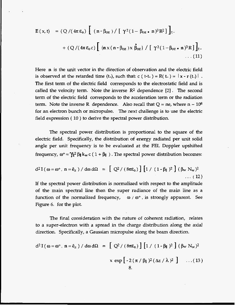
Here n is the unit vector in the direction of observation and the electric field is observed at the retarded time (t-), such that: c ( t-t- ) = R( t- ) = 1 x - r (t-) 1 . The first term of the electric field corresponds to the electrostatic field and is called the velocity term. Note the inverse R2 dependence [2] . The second term of the electric field corresponds to the acceleration term or the radiation term. Note the inverse R dependence. Also recall that Q = ne, where n - 108 for an electron bunch or micropulse. The next challenge is to use the electric field expression ( 10 ) to derive the spectral power distribution.
The spectral power distribution is proportional to the square of the electric field. Specifically, the distribution of energy radiated per unit solid angle per unit frequency is to be evaluated at the FEL Doppler upshifted
frequency, a+ = Ti2 pi1 kw c ( 1 + ) . The spectral power distribution becomes:
* . . (12 ) If the spectral power distribution is normalized with respect to the amplitude of the main spectral line then the super radiance of the main line as a function of the normalized frequency, o / a+, is strongly apparent. See Figure 6. for the plot.
The final consideration with the nature of coherent radiation, relates to a super-electron with a spread in the charge distribution along the axial direction. Specifically, a Gaussian micropulse along the beam direction.

Recall the equation of the radiation spectrum for a super point charge traveling along the beam axis, ( 12 ). The difference between equation (12 ) and equation ( 13 ) is the exponential coherence function in ( 13 ) which describes how the energy density in the main spectral line decreases as the bunch length to radiation wavelength ratio increases. See Figure 7. for a plot of the coherence function as a function of the bunch length to radiation wavelength ration.
W. Single Pass Model for the Signal Gain
The growth of coherent radiation in a single pass of a prebunched electron beam is calculated. The Single Pass Model uses two approaches to calculate the signal gain 1). the expression of Colson [3] which gives the energy loss ( or gain ) of an electron propagating through an undulator in the presence of a circularly polarized electromagnetic wave. Colson's calculation of the gain is applied to short electron pulses inside much longer radiation pulses. The signal gain, in the single pass, is assumed to be low or in the linear gain region. The Colson equation is :
. . . (14)
2). The second approach to the signal gain calculation is based upon the following assumptions: a) The electron beam is cold, b) The electron beam - radiation interactions take place only in the wiggler segment of the resonator. c) The electron bunch length is much smaller than the radiation wavelength, therefore the bunch can be considered a super-charged electron. d) The fluctuations in the charge density are minimal and each electron, or a sheet of super charge, has an orbit is uncorrelated with all other sheets of charge. e) The contribution of the entire spectrum of spatial modes is considered in the calculation. f) The ability to tune the signal gain by adjusting the distance between the mirrors. g) The ability to do a multi pass analysis of the signal gain.
9.

Where the definition of each term is given below : lb
O b
YO
Pw
Fc
: the length of the electron bunch : the peak beam plasma frequency : the electron beam energy before entering the resonator. : beta, ( vw / c ) for the wiggler velocity : the coherent filling function, cq, / CR, usually the cross section
of the light beam is greater than the cross section of the electron beam.
n , m N
: the spatial mode numbers : the number of passes through the resonator
6L : L - L m , whereL, =(2L) / (2pO) Gull : = exp[ - i ( k n - k m ) ( l - p O ) ( L o / p O ) h : structure function for the beam shape, use the square pulse
profile pnm =sh[(kn-km)( lb / 2 ) 1 / [ (kn-km)( lb / 2 ) 1 Pm z
: the frequency mismatch, pm = voz ( kw + km ) - O,
: o I ( time within the wiggler ) 5 ( Lw / voz )
10.

V. Application of the Single Pass Model to the Proposed Prebunched FEL a t M.I.T.
The Single Pass Model is applied to a set of parameters which describe the proposed FEL project at M.I.T. The signal gain is calculated using two methods.
M. I . T. Proposed Prebunched FEL
I n p u t P a r a m e t e r s
A c c e l e r a t o r
Voltage ( M e V ) Frequency ( G H z ) Macro pulse ( y s ) Macropulse I ( A ) Bunch Phase ( deg)
Wiggler
Periods Wanelengths ( 1 Magnetic Field ( kG )
Oscillator
Mirror Diameter ( cm ) Initial Power ( W ) Resonator Length ( cm )
RF Linac
14 17 1 0.250 1
25 8 1
4 0.01 400
11.

O u t p u t P a r a m e t e r s
Genera 1 Parameters
Beam Energy ( gamma) Undulator Constant RF Wavelength (wd RF Frequency ( ) Macropulse Charge Micropulses I Macropulse
Micro pulse ( p s ) Micropulse Charge ( p a Micropulse Current ( A ) Micropulse Length ( p m ) Micropulse Length I RF Length Micropulse Spacing ( c m ) Micropulse Spacing ( p s )
28.397 0.744 63.331 4737. 250. 17,000.
0.163 14.706 90. 49.02 0.774 1.765 58.824
Calculated Si-mal Gain for the Sinde Pass
Method Value
Ay/y, Colson ( 3.5 f 0.3 x 10⁻⁴
Gn m , ( modified Sprangle ) ( Treadwell 1
(3.5 f 0.3 ) x 10-4
Signal gain is calculated using the proposed M.I.T. FEL parameters. The errors relate to uncertainties in energy loss for the Colson method, and uncertainties in the filling factor, Fc , that is used in the modified Sprangle [3] Treadwell calculation. See Figure 8. and Figure 9. for single pass gain distributions.
12.

VI. Figures and Plots
13.

Figure 1. F E L Description
B L - f- I
z 0
-I t + l W
t+ z = L
0
n Z El-)" 0
z
Wiggler Resonator 4
---c Z -3 z = L + L I
O w l z = L
radiative pulse m electron micro pulse
14