calculating surface roughness values with …...page 38 calculating surface roughness values with...
TRANSCRIPT
Page 38
Calculating Surface Roughness Values with Different Parameters
by Turning Process Using Taguchi Method
J.Vijaya Bhaskar
M.Tech- Advance Manufacturing Systems,
Department Mechanical Engineering,
Hyderabad Institute of Technology and Management,
Telangana, India.
V.Venkata Phanibabu
Assistant Professor & HoD
Department Mechanical Engineering,
Hyderabad Institute of Technology and Management,
Telangana, India.
Abstract
Turning process is one of the most fundamental
machining processes used in the manufacturing
industry. The process of turning is influenced by
many factors such as cutting velocity, feed rate, depth
of cut, geometry of cutting tool, and cutting
conditions etc., to name a few. In machining
operations, achieving the desired surface quality of
the machined product is really a challenging job.
This is due to the fact that quality is highly
influenced by process parameters directly or
indirectly.The present experimental study is
concerned with the optimization of cutting
parameters in wet turning of EN31 steel. In the
present work, turning operations were carried out on
EN31 steel by carbide P-30 cutting tool in wet
condition and the combination of the optimal levels
of the parameters was obtained by using the Taguchi
optimization method.
The Analysis of Variance (ANOVA) and Signal-to-
Noise ratio were used to study the performance
characteristics in turning operation. The results
obtained by this research will be useful to other
similar type of study and can be helpful for further
research on tool vibrations, cutting forces etc.
INTRODUCTION
Turning is the removal of metal from the outer
diameter of a rotating cylindrical work piece. Turning
is used to reduce the diameter of the work piece,
usually to a specified dimension, and to produce a
smooth finish on the metal. Often the work piece will
be turned so that adjacent sections have different
diameters.
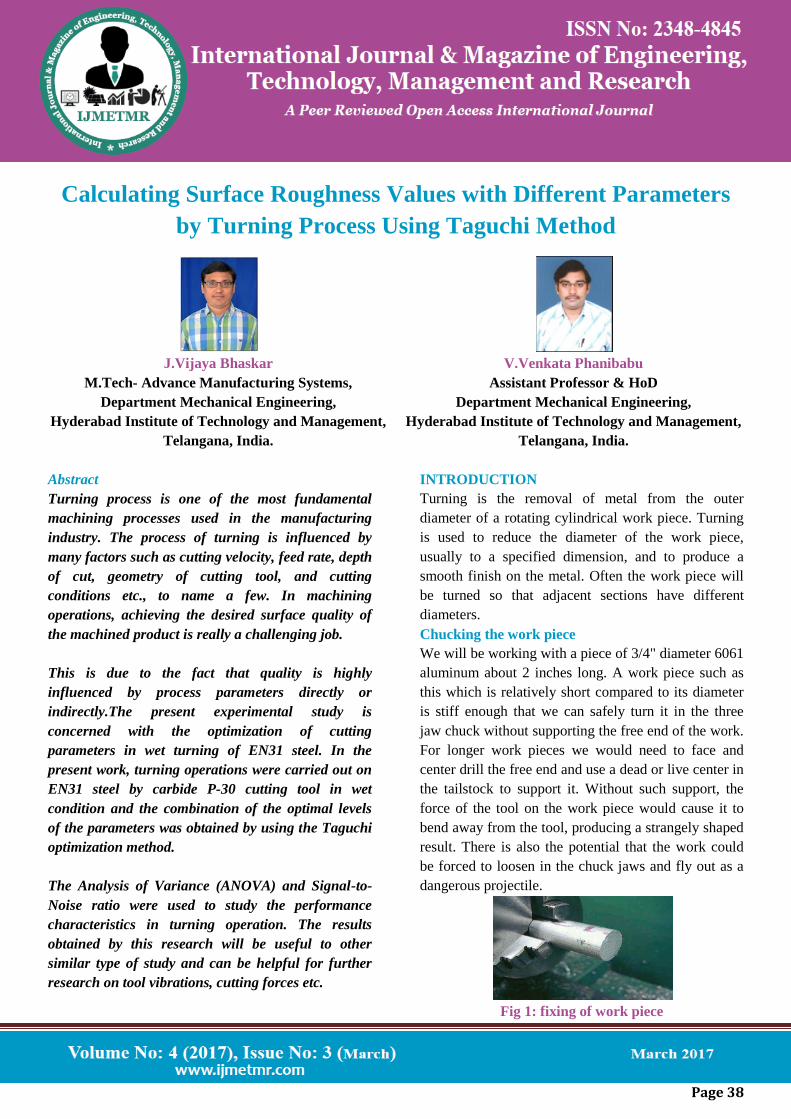
Chucking the work piece
We will be working with a piece of 3/4" diameter 6061
aluminum about 2 inches long. A work piece such as
this which is relatively short compared to its diameter
is stiff enough that we can safely turn it in the three
jaw chuck without supporting the free end of the work.
For longer work pieces we would need to face and
center drill the free end and use a dead or live center in
the tailstock to support it. Without such support, the
force of the tool on the work piece would cause it to
bend away from the tool, producing a strangely shaped
result. There is also the potential that the work could
be forced to loosen in the chuck jaws and fly out as a
dangerous projectile.
Fig 1: fixing of work piece
Page 39
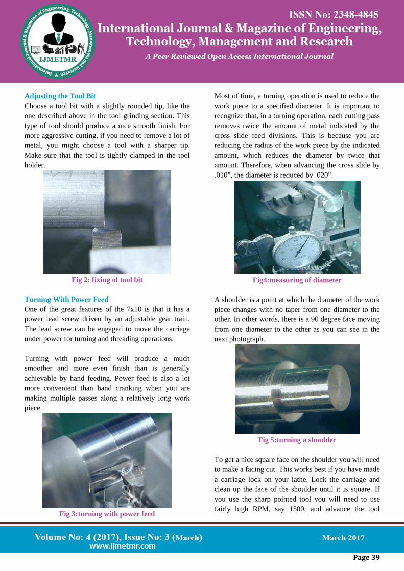
Adjusting the Tool Bit
Choose a tool bit with a slightly rounded tip, like the
one described above in the tool grinding section. This
type of tool should produce a nice smooth finish. For
more aggressive cutting, if you need to remove a lot of
metal, you might choose a tool with a sharper tip.
Make sure that the tool is tightly clamped in the tool
holder.
Fig 2: fixing of tool bit
Turning With Power Feed
One of the great features of the 7x10 is that it has a
power lead screw driven by an adjustable gear train.
The lead screw can be engaged to move the carriage
under power for turning and threading operations.
Turning with power feed will produce a much
smoother and more even finish than is generally
achievable by hand feeding. Power feed is also a lot
more convenient than hand cranking when you are
making multiple passes along a relatively long work
piece.
Fig 3:turning with power feed
Most of time, a turning operation is used to reduce the
work piece to a specified diameter. It is important to
recognize that, in a turning operation, each cutting pass
removes twice the amount of metal indicated by the
cross slide feed divisions. This is because you are
reducing the radius of the work piece by the indicated
amount, which reduces the diameter by twice that
amount. Therefore, when advancing the cross slide by
.010", the diameter is reduced by .020".
Fig4:measuring of diameter
A shoulder is a point at which the diameter of the work
piece changes with no taper from one diameter to the
other. In other words, there is a 90 degree face moving
from one diameter to the other as you can see in the
next photograph.
Fig 5:turning a shoulder
To get a nice square face on the shoulder you will need
to make a facing cut. This works best if you have made
a carriage lock on your lathe. Lock the carriage and
clean up the face of the shoulder until it is square. If
you use the sharp pointed tool you will need to use
fairly high RPM, say 1500, and advance the tool
Page 40
slowly or you will get little grooves from the pointed
tip instead of a nice smooth finish.
Fig 6: pointed tool to work piece
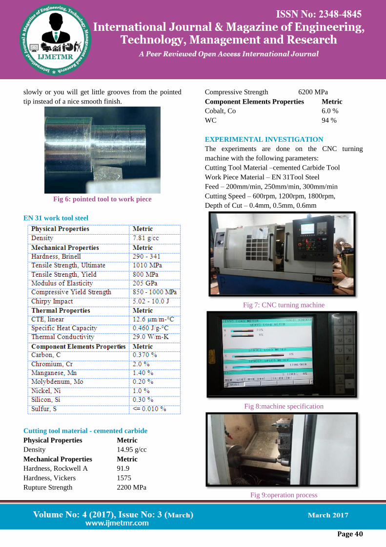
EN 31 work tool steel
Cutting tool material - cemented carbide
Physical Properties Metric
Density 14.95 g/cc
Mechanical Properties Metric
Hardness, Rockwell A 91.9
Hardness, Vickers 1575
Rupture Strength 2200 MPa
Compressive Strength 6200 MPa
Component Elements Properties Metric
Cobalt, Co 6.0 %
WC 94 %
EXPERIMENTAL INVESTIGATION
The experiments are done on the CNC turning
machine with the following parameters:
Cutting Tool Material –cemented Carbide Tool
Work Piece Material – EN 31Tool Steel
Feed – 200mm/min, 250mm/min, 300mm/min
Cutting Speed – 600rpm, 1200rpm, 1800rpm,
Depth of Cut – 0.4mm, 0.5mm, 0.6mm
Fig 7: CNC turning machine
Fig 8:machine specification
Fig 9:operation process
Page 41
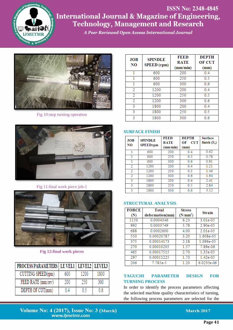
Fig 10:step turning operation
Fig 11:final work piece job-1
Fig 12:final work pieces
SURFACE FINISH
STRUCTURAL ANALYSIS
TAGUCHI PARAMETER DESIGN FOR
TURNING PROCESS
In order to identify the process parameters affecting
the selected machine quality characteristics of turning,
the following process parameters are selected for the
Page 42
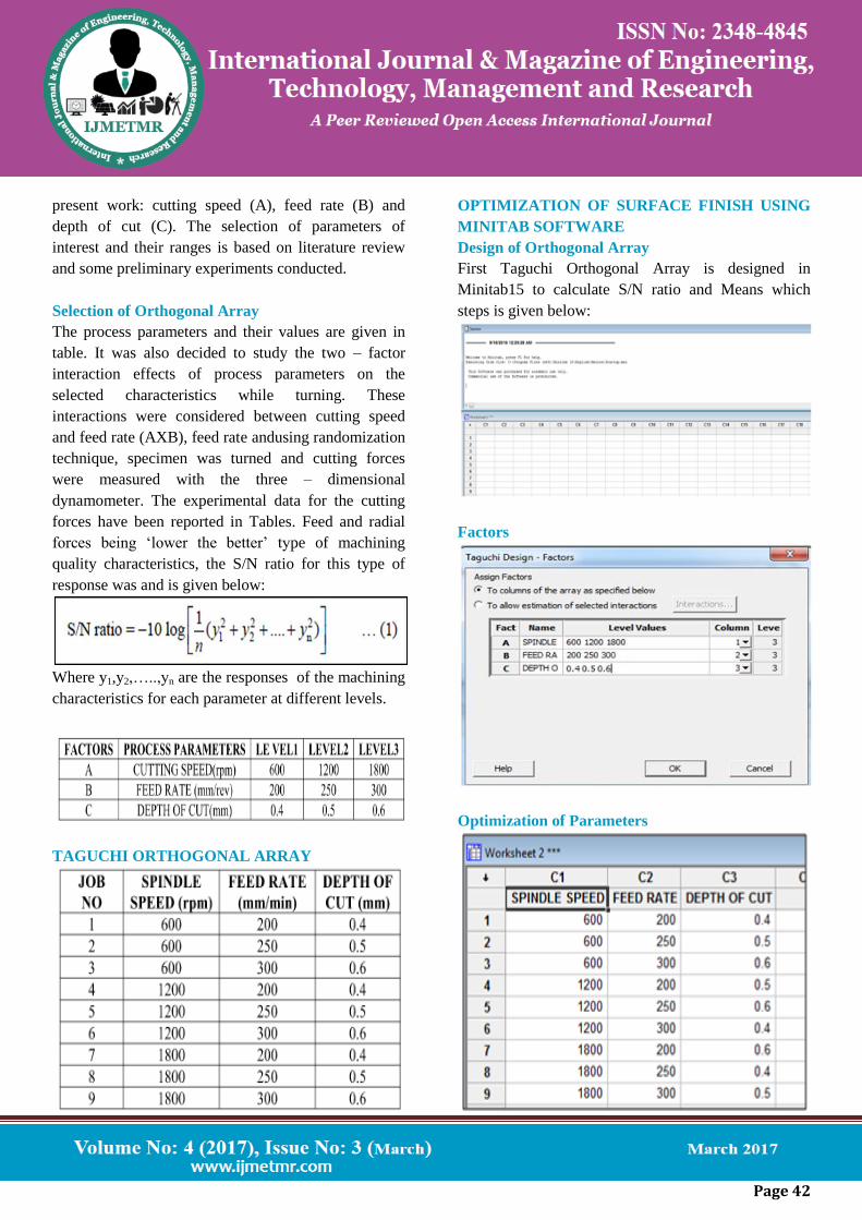
present work: cutting speed (A), feed rate (B) and
depth of cut (C). The selection of parameters of
interest and their ranges is based on literature review
and some preliminary experiments conducted.
Selection of Orthogonal Array
The process parameters and their values are given in
table. It was also decided to study the two – factor
interaction effects of process parameters on the
selected characteristics while turning. These
interactions were considered between cutting speed
and feed rate (AXB), feed rate andusing randomization
technique, specimen was turned and cutting forces
were measured with the three – dimensional
dynamometer. The experimental data for the cutting
forces have been reported in Tables. Feed and radial
forces being ‘lower the better’ type of machining
quality characteristics, the S/N ratio for this type of
response was and is given below:
Where y1,y2,…..,yn are the responses of the machining
characteristics for each parameter at different levels.
TAGUCHI ORTHOGONAL ARRAY
OPTIMIZATION OF SURFACE FINISH USING
MINITAB SOFTWARE
Design of Orthogonal Array
First Taguchi Orthogonal Array is designed in
Minitab15 to calculate S/N ratio and Means which
steps is given below:
Factors
Optimization of Parameters
Page 43
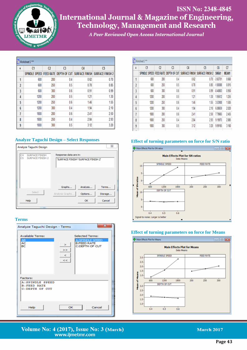
Analyze Taguchi Design – Select Responses
Terms
Effect of turning parameters on force for S/N ratio
Effect of turning parameters on force for Means
Page 44
SUMMARY
Taguchi method stresses the importance of studying
the response variation using the signal–to–noise (S/N)
ratio, resulting in minimization of quality characteristic
variation due to uncontrollable parameter. The cutting
force is considered as the quality characteristic with
the concept of "the smaller-the-better". The S/N ratio
for the smaller-the-better is:
S/N = -10 *log(Σ(Y2)/n))
Where n is the number of measurements in a trial/row,
in this case, n=1 and y is the measured value in a
run/row. The S/N ratio values are calculated by taking
into consideration above Eqn. with the help of
software Minitab 17.
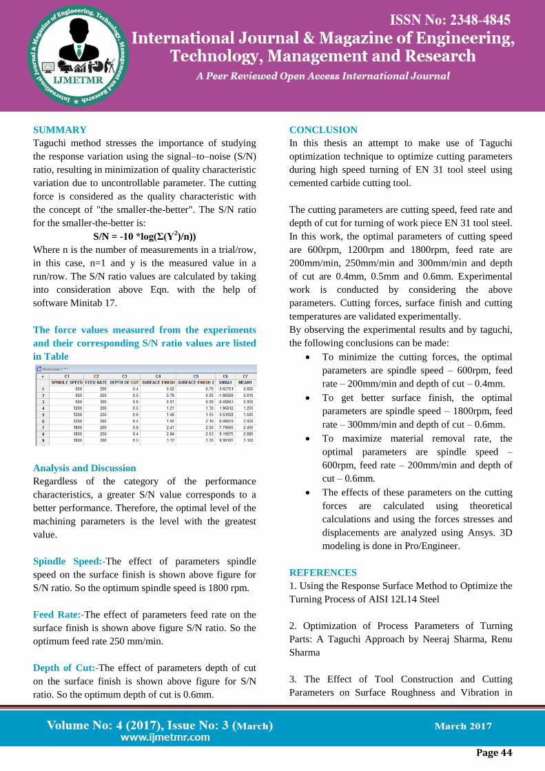
The force values measured from the experiments
and their corresponding S/N ratio values are listed
in Table
Analysis and Discussion
Regardless of the category of the performance
characteristics, a greater S/N value corresponds to a
better performance. Therefore, the optimal level of the
machining parameters is the level with the greatest
value.
Spindle Speed:-The effect of parameters spindle
speed on the surface finish is shown above figure for
S/N ratio. So the optimum spindle speed is 1800 rpm.
Feed Rate:-The effect of parameters feed rate on the
surface finish is shown above figure S/N ratio. So the
optimum feed rate 250 mm/min.
Depth of Cut:-The effect of parameters depth of cut
on the surface finish is shown above figure for S/N
ratio. So the optimum depth of cut is 0.6mm.
CONCLUSION
In this thesis an attempt to make use of Taguchi
optimization technique to optimize cutting parameters
during high speed turning of EN 31 tool steel using
cemented carbide cutting tool.
The cutting parameters are cutting speed, feed rate and
depth of cut for turning of work piece EN 31 tool steel.
In this work, the optimal parameters of cutting speed
are 600rpm, 1200rpm and 1800rpm, feed rate are
200mm/min, 250mm/min and 300mm/min and depth
of cut are 0.4mm, 0.5mm and 0.6mm. Experimental
work is conducted by considering the above
parameters. Cutting forces, surface finish and cutting
temperatures are validated experimentally.
By observing the experimental results and by taguchi,
the following conclusions can be made:
To minimize the cutting forces, the optimal
parameters are spindle speed – 600rpm, feed
rate – 200mm/min and depth of cut – 0.4mm.
To get better surface finish, the optimal
parameters are spindle speed – 1800rpm, feed
rate – 300mm/min and depth of cut – 0.6mm.
To maximize material removal rate, the
optimal parameters are spindle speed –
600rpm, feed rate – 200mm/min and depth of
cut – 0.6mm.
The effects of these parameters on the cutting
forces are calculated using theoretical
calculations and using the forces stresses and
displacements are analyzed using Ansys. 3D
modeling is done in Pro/Engineer.
REFERENCES
1. Using the Response Surface Method to Optimize the
Turning Process of AISI 12L14 Steel
2. Optimization of Process Parameters of Turning
Parts: A Taguchi Approach by Neeraj Sharma, Renu
Sharma
3. The Effect of Tool Construction and Cutting
Parameters on Surface Roughness and Vibration in
Page 45
Turning of AISI 1045 Steel Using Taguchi Method by
Rogov Vladimir Aleksandrovich, GhorbaniSiamak
4. Parametric investigation of turning process on mild
steel aisi 1018 material by J. M. Gadhiya, P. J. Patel
5. Evaluation and Optimization of Machining
Parameter for turning of EN 8 steel by Vikas B.
Magdum, Vinayak R. Naik
6. Analyses of surface roughness by turning process
using Taguchi method by S. Thamizhmanii, S.
Saparudin, S. Hasan
7. Application of Taguchi Method for Optimizing
Turning Process by the effects of Machining
Parameters by Krishankant, JatinTaneja, MohitBector,
Rajesh Kumar
8. Multi-Objective Optimization of the Cutting Forces
in Turning Operations Using the Grey-Based Taguchi
Method by Yigit
9. Experimental investigation of Material removal rate
in CNC turning using Taguchi method by Kamal,
Anish and M.P.Garg
10. Optimization of Cutting Parameters of Composite
Materials using Genetic Algorithm by Dhavamani and
Alwarsamy