calculating contained firing facility (cff) explosive
TRANSCRIPT

UCRL-ID- 132204 Rev 1
Calculating Contained Firing Facility (CFF) Explosive Firing Zones
J. W. Lyle
February 3,1999 \
This is an informal report intended primarily for internal or limited external distribution. The opinions and conclusions stated are those of the author and may or may not be those of the Laboratory. Work performed under the auspices of the U.S. Department of Energy by the Lawrence Livermore National Laboratory under Contract W-740%ENG-48.

DISCLAIMER
This document was prepared as an acccount of work sponsored by an agency of the United States Government. Neither the United States Government nor the University of California nor any of their employees, makes any warranty, express or implied, or assumes any legal Rabiity or responsibiity for the accuracy, completeness, or usefulness of any information, apparatus, product, or process disclosed, or repmsents that its use would not infringe privately own rights. Reference herein to any specific commercial products, process, or service by trade name, trademark, manufacturer, or otherwise, does not necessarily constitute or imply ik endorsement, recommendation, or favoring by the United States Government or the University of California. .The views and opinions of authors expressed herein do not necessarily state or reflect those of the United States Government or the University of California, and shall not be used for advertising or product endorsement purposes.
Thlsn?porthasbeenreproduced directly from the best available copy.
Available to DOE and DOE contractors tiom the Office of Scientific and Technical Information
P.O. Box 62, Oak Ridge, TN 37831 Prices available from (615) 5764401, PlS 6268401
Available to the public from the National Technical Information Service
us. Department of commerce 5285 Port Royal Rd.,
Springfield, VA 22161

CALCULATING CONTAINED FIRING FACILITY (CFF) EXPLOSIVE FIRING ZONES
J. W. Lyle
February 3, 1999
I. INTRODUCTION
The University awarded a contract for the design of the Contained Firing Facility (CFF) to Parsons Infrastructure & Technology, Inc. of Pasadena, California. The Laboratory specified that the firing chamber be able to withstand repeated firings of 60 Kg of explosive located in the center of the chamber, 4 feet above the floor, and repeated firings of 35 Kg of explosive at the same height and located anywhere within 2 feet of the edge of a region on the floor called the anvil. Other requirements were that the chamber be able to accommodate the penetrations of the existing bullnose of the Bunker 801 flash X-ray machine and the roof of the underground camera room. For the sole purpose of calculating the explosive firing zones, it is assumed that the above requirements will be met by the completed facility.
These requirements and provisions for blast resistant doors formed the essential basis for the design. The design efforts resulted in a steel-reinforced concrete structure measuring (on the inside) 55 x 5 1 feet by 30 feet high. The walls and ceiling are to be approximately 6 feet thick. Because the 60 Kg charge is not located in the geometric center of the volume and a 35 Kg charge could be located anywhere in a prescribed area, there will be different dynamic pressures and impulses on the various walls, floor, and ceiling depending upon the weights and locations of the charges.
The detailed calculations and specifications to achieve the design criteria were performed by Parsons and are included in Reference 1. The 12 page abstract in this Reference is especially valuable.
Reference 2, Structures to Resist the Effects of Accidental Explosions, (TM5-1300) is the primary design manual for structures of this type. It includes an analysis technique for the calculation of blast loadings within a cubicle or containment-type structure. Parsons used the TM5- 1300 methods to calculate the loadings on the various firing chamber surfaces for the design criteria explosive weights and locations. At LLNL the same methods were then used to determine the firing zones for other weights and elevations that would give the same or lesser loadings. Although very laborious, a hand calculation of the various variables is possible and an example is given in Appendix C. A code called “SHOCK” is available to perform these calculations rapidly and a version runs on a personal computer. The original code was developed by the firm Amman and Whitney which they called “Paimpres”; this was modified to its present form by the U.S. Naval Civil Engineering Laboratory. Parsons used the SHOCK code extensively as well as several single and multiple degree of freedom codes which were provided by the U.S. Corps of Engineers. In addition, Parsons based their analysis/design on procedures stipulated in the publication DOE/TIC- 11268, A Manual for the Prediction of Blast and Fragment Loadings on Structures.
Loadings on structures in Reference 2 and in calculations performed with the SHOCK code are based on weights of explosives in pounds of TNT equivalent. The equivalency of an explosive (for its blast effects on structures) is calculated by the ratio of its heat to detonation to that of TNT. We intend to use C-4 for testing the response of the firing chamber. Various values of the ratio for C-4 are available, Reference 2 lists numbers leading to a ratio of 1.15, while 1.13 is the ratio calculated from numbers given in the LLNL Explosives Handbook, (Reference 3). Parsons used a ratio value of 1.3 for generic high explosive to TNT equivalency. For design purposes, Reference 2 recommends a 20% increase in explosive weight. Parsons adopted this recommendation. Therefore, for calculational purposes, 60 Kg of generic high explosive was taken to be equivalent to 206.3 pounds of TNT. That is, 60 Kg x 2.204 Lb/Kg x 1.3 x 1.2 = 206.3 Lb. VW.

II. CALCULATIONAL DETAILS
In section 2-14.2.1. of Reference 2, it is written:
“An approximate method for the calculation of the internal shock pressures has been developed using theoretical procedures based on semi-empirical blast data and on the results of response tests on slabs. The calculated average shock pressures have been compared with those obtained from the results of tests of a scale-model steel cubicle and have shown good agreement for a wide range of cubicle configurations. This method consists of the determination of the peak pressures and impulses acting at various points of each interior surface and then integrating to obtain the total shock load. In order to simplify the calculation of the response of a protective structure wall to these applied loads, the peak pressures and total impulses are assumed to be uniformly distributed on the surface. The peak average pressure and the total average impulse are given for any wall surface. The actual distribution of the blast loads is highly irregular, because of the multiple reflections and time phasing and results in localized high shear stresses in the element. The use of the average blast loads, when designing, is predicated on the ability of the element to transfer these localized loads to regions of lower stress. Reinforced concrete with properly designed shear reinforcement and steel plates exhibit this characteristic.”
The procedure for the determination of the shock loads was programmed for solutions on a digital computer. The results are presented in Reference 2 on 96 figures. Fortunately, the text and figures of TM51300 are available as computer software which includes the means to read the graphical data. In this way it is easy to obtain peak reflected pressure, impulse, pulse length and other variables as a function of the scaled distance (Z=R/W*1/3). In this expression, R is the distance from charge center to the surface in question and W is the weight of explosive in equivalent TNT pounds. The CFF firing chamber geometry is included in the range of the plotted variables so that extrapolation was not necessary, but interpolation between as many as 6 curves was required to tit some charge locations. The use of the SHOCK code greatly assists this process. Again from Reference 2, “The wall (if any) parallel and opposite to the surface in question has a negligible contribution to the shock loads for the range of parameters used and was therefore not considered.”
The analysis leads to the conclusion that each of the chamber surfaces can be characterized by the peak average pressure it would experience. For the floor, it is obvious that the maximum charge at 4 feet elevation yields the highest pressure, which at a point directly beneath the charge would be approximately 15,541 psi. The same charge gives the highest average pressure on the ceiling, approximately 78 psi. The various locations of a 35 Kg charge two feet inside the anvil edge yield the highest average pressures on the walls according to the following table.
In this table, the maximum average pressures for the floor and ceiling (400.9 psi and 78 psi) are those calculated with the SHOCK code by Parsons for the “Governing” load case L2 and can be found in Reference 1. The other pressures in this table were calculated with the SHOCK code at Livermore.
2

TABLE I
SHOCK CODE CALCULATIONS OF
PRESSURES ON THE VARIOUS SURFACES
Explosive Charges at 4-foot elevation
Surface Floor
Ceiling W. wall
E wall N wall
S wall
Pressure at Point Nearest charge
psi 15,541.3
163.5 2408.7
664.2 2602.9
229.7
Maximum Average Pressure on Entire
Surface psi
400.9 78
234.7
126.9 209
80
Caused By 206.3 Lb. TNT, centered 206.3 Lb. TNT, centered 120.3 Lb. TNT, 8.53 feet from wall (as if no bullnose were present) 120.3 Lb. TNT, 13 feet from wall 120.3 Lb. TNT, at NE comer of the anvil 120.3 Lb. TNT, centered, 19.7 feet from S wall
Initially, a series of calculations was performed for the 4-foot elevation to determine where 60 kg of explosive could be placed so that the above tabulated average pressures on the floor, roof and walls would not be exceeded. The area on the anvil for the location of 35 Kg charges was taken as given. The analysis was then extended at 5 Kg intervals to fill in the space on the anvil between 35Kg and 60 Kg. The same analysis also located the 1 -Kg line. Near the north wall there is a trench in the floor so we thought it prudent to move the l-Kg a foot or so inwards to avoid bending the trench cover plates. Intermediate explosive weights between the north l-kg line and the 35 Kg line on the anvil were placed linearly between these two boundaries as an expedient even though it is recognized that the analysis is non-linear. The area south of the 35 Kg line is limited to a total distributed explosive quantity of 1.5 Kg (mirror pads) in order to minimize stresses on the camera room roof. At most, 10 mirror pads could be used on a single shot. The pad’s present explosive weight is 75 grams, but anticipated future design modifications may call for up to 150 grams each.
The SHOCK code features a reduced area calculation. This scheme was used to calculate the average pressures and the impulse on the inner door frame of the equipment blast door as if the door were there rather than its actual location at the outer wall, 6 feet further away from the explosive. The results were then used to adjust the map profiles so that the design criteria of pressure and impulse at the virtual door would not be exceeded for any explosive weight or location.
The explosive weights at elevations less than 4 feet were calculated so that the peak pressures on the floor would not exceed 15,54 1.3 psi. The explosive weights at elevations greater than 4 feet were calculated so that the peak average pressure on the ceiling would not exceed 78 psi.
III. TYPICAL SHOT CONFIGURATIONS
Upon initial operation, the maximum total generic high explosive charge will be limited to 60 Kg. Management may wish to amend this requirement after the initial testing of the tiring chamber is accomplished and when sufficient operating experience has been accumulated. Firing zone maps have been prepared for eleven explosive weights and for several elevations, (Appendix A).
A single bare or cased explosive charge can be placed anywhere within the firing zone appropriate to its weight. Permissible locations for single charge intermediate weights can be determined by simple linear interpolation between the several maps.
For optical diagnostics, a typical shot consists of a main charge and four explosively-driven illuminating “candles” of 1.8 Kg charge weight each. Again, the total weight of the distributed explosives, including the optical port hole mirror pads, may not exceed 60 Kg. The weight of the main charge will determine the appropriate firing zone. However, in the absence of any attenuating provisions, and in order not to exceed the tabulated pressure of 15,541.3 psi on the floor, (Table I), the 1.8 Kg candles may be placed no closer than 13 to 14 inches from the floor.
Multiple explosive charges, split charges, and shaped charges present unusual shot setup configuration requirements. Care must be taken not only to limit the blast pressures on the firing chamber surfaces but also to protect the structures from high velocity jets. Part of management’s shot approval process includes a peer review panel. Experiments of the type considered in this paragraph will be submitted to the panel for further analysis and approval.
IV. CONCLUSIONS
The curves in Appendix A are meant to be used by ramrods, physicists, engineers, and bunker personnel for the safe placement of explosives in the facility. The objective is to maintain a minimum safety factor of 1.7 to the elastic limit for the most heavily stressed chamber element. It is important to point out that the curves are based solely on calculations with the assumption that the yet-to-be-constructed firing chamber will meet its design objectives. The firing chamber will be fitted with gauges to measure strain. As testing and operating experience are accumulated, the map profiles may be adjusted. In addition, deviations from these maps are possible with appropriate analyses, approval, and planning, and through the use of blast attenuation and mitigation measures.
The most heavily stressed element in the firing chamber will be the floor. Various configurations of attenuating materials have been tested that minimize blast damage to the floors of explosive testing chambers. Some examples can be found in Reference 4. Additional experimental studies are now being planned as the basis for the design of an attenuating system for use in the firing chamber. Our intention is to use such a system until experience shows that it may not be necessary.
V.
1.
2.
3.
4.
REFERENCES
Site 300, Contained Firing Facility, Final Structural Chamber Calculations, LLNL Contract No. B345381, Parsons Job No. 732925, May 29, 1998.
Departments of the Army, Navy, and Air Force, Structures to Resist the Efsects OfAccidental Explosions, Army TM 5- 1300, Headquarters, Washington, D.C. 19 November 1990.
B. M. Dobratz and P. C. Crawford, LLNL Explosives Handbook, Properties of Chemical Explosives and Explosive Explosive Simulants, Lawrence Livermore National Laboratory, Livermore, California, UCRL-52997 Change 2, January 3 1, 1985.
J. W. Pastmak, C. F. Baker, and L. F. Simmons, Quarter-Scale Close-in Blast-Loading Experiments in Support of the Planned’contained Firing Facility, Lawrence Liver-more National Laboratory, Livermore, California, UCRL-JC-116822, July 27, 1994.
4

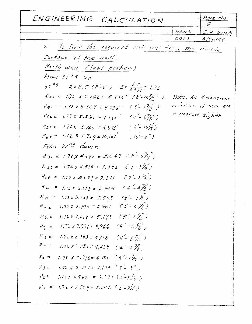
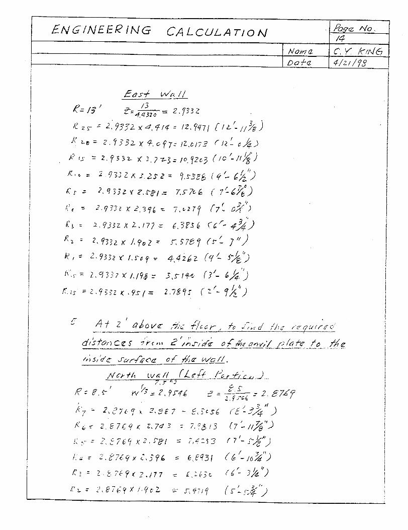
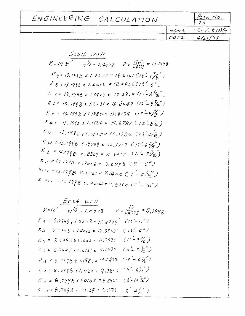
APPENDIX A
Explosive firing zone maps are given for six elevations 1,2, 3, 3.5,4, 8, and 12 feet above the floor. The region to the south of the 35 Kg line, over the optics room roof, is limited to a total distributed explosive weight of 1.5 Kg. This will accommodate 10 optical turning mirror explosive pads of 150 grams each.


CUllJNE OF WSlM Fm AlxxlEMlm BAY
. . . . I..$-. ‘.: :p.’
\ / .: .j:,.\
. : . 3: :.
?i?GEFAcE . : . 7”
ZL-
* ‘7 wul
r
b- +-
1 foot Above Floor D
- 1.5 Kq -/
Preliminary CFF - HARDENED CHAMBER EXPLOSIVE FIRING ZONES
October 20, 1998

!! I..! .:. . : 7.
- - F c - I i - - I

I 1
I I I
1
J

E
8 w m
y” w
1 ’

4 r I
R
\ \
/


/ I’ I I I I I
f
%
w
I I k 0
-
\ /
. .‘I . . . I
I t I ii

APPENDIX B
The SHOCK code calculations for the 206.3 Lb. charge of TNT are given for the floor and roof of the firing chamber to illustrate the technique and because this charge results in the highest loading on the respective surfaces. This is followed by calculations for the 120.3 Lb. charge giving the maximum pressures on the East and West walls (no builnose accounted for). One of a series of code calculations is given to illustrate the reduced area feature of the code. In this case, a virtual blast door on the inside of the chamber wall is being considered. The two remaining plots are the calculated peak average pressures and impulses on the virtual door from charges of various weights as they are moved along a bisecting normal line to the door. Several hundred individual SHOCK code calculations were made for various charge weights and locations. They can be found on electronic media in the project files.


1
PROGRAM SHOCK VERSION 1.0
********************************************************* PROGRAM FOR CALCULATION OF AVERAGE BARRIER REFLECTED
SHOCK PRESSURES AND IMPULSES DUE TO AN INCIDENT WAVE AND REFLECTED WAVES FROM ONE TO FOUR REFLECTION SURFACES.
ORIGINAL PROGRAM "PAIMPRES' DEVELOPED BY AMMANN AND W H ITNEY MODIFIED TO "SHOCK' BY NAVAL CIVIL ENGINEERING LAB
INPUT DATA +
DATA SET TITLE: A206FS f-//f
A. CHARGE W E IGHT, LBS ...................... B. DISTANCE TO BLAST SURFACE, FT ........... C. W IDTH OF BLAST SURFACE, FT .............. D. HEIGHT OF BLAST SURFACE, FT ............. E. HORIZONTAL (X) DISTANCE TO CHARGE
FROM REFLECTING SURFACE NO. 2, FT ....... F. VERTICAL (Y) DISTANCE TO CHARGE
FROM REFLECTING SURFACE NO. 1, FT ....... G. REFLECTING SURFACES
"1" FOR FULL REFLECTION, "0" FOR NONE SURFACE 1 (FLOOR) ..................... SURFACE 2 (LEFT SIDEWALL) ............. SURFACE 3 (CEILING) ................... SURFACE 4 (RIGHT SIDEWALL) ............
H. REDUCED SURFACE CALCULATION .............
206.30 4.00
55.00 51.00
27.50
25.50
1 1 1 1
NO
ANALYSIS RESULTS +
AVERAGE SHOCK PRESSURE AND SCALED SHOCK IMPULSE ON BLAST SURFACE DUE TO WAVES OFF REFLECTING SURFACES DUE TO INCIDENT WAVE
SURFACE 1 2 3 4 IMPULSE 8.6 7.9 8.6 7.9 24.3
PRESSURE 16.9 14.3 16.9 14.3 400.9
MAXIMUM AVERAGE SHOCK PRESSURE AND TOTAL AVERAGE SHOCK IMPULSE ON BLAST SURFA SCALED IMPULSE 57.2
IMPULSE 338.2 PRESSURE 400.9
IMPULSE DURATION ON BLAST SURFACE = 1.69 MS SCALED IMPULSES HAVE BEEN DIVIDED BY W **(1/3) = 5.91 SCALED IMPULSES ARE PSI-MS/LBS**1/3, IMPULSES ARE PSI-MS, PRESSURES ARE PSI

PROGRAM SHOCK VERSION 1.0
********************************************************* PROGRAM FOR CALCULATION OF AVERAGE BARRIER REFLECTED
SHOCK PRESSURES AND IMPULSES DUE TO AN INCIDENT WAVE AND REFLECTED WAVES FROM ONE TO FOUR REFLECTION SURFACES.
ORIGINAL PROGRAM "PAIMPRES" DEVELOPED BY AMMANN AND WHITNEY MODIFIED TO "SHOCK" BY NAVAL CIVIL ENGINEERING LAB
INPUT DATA
DATA SET TITLE: A206RS @&df
A. CHARGE WEIGHT, LBS...................... 206.30 26.00 55.00 51.00
B. DISTANCE TO BLAST SURFACE, FT........... C. WIDTH OF BLAST SURFACE, FT.............. D. HEIGHT OF BLAST SURFACE, FT............. E. HORIZONTAL (X) DISTANCE TO CHARGE
FROM REFLECTING SURFACE NO. 2, FT....... F. VERTICAL (Y) DISTANCE TO CHARGE
FROM REFLECTING SURFACE NO. 1, FT....... G. REFLECTING SURFACES
"1" FOR FULL REFLECTION, "0" FOR NONE SURFACE 1 (FLOOR)..................... SURFACE 2 (LEFT SIDEWALL)............. SURFACE 3 (CEILING).......,........... SURFACE 4 (RIGHT SIDEWALL)............
H. REDUCED SURFACE CALCULATION.............
ANALYSIS RESULTS
AVERAGE SHOCK PRESSURE AND SCALED SHOCK DUE TO WAVES OFF REFLECTING SURFACES
SURFACE 1 2 3 4 IMPULSE 12.7 10.8 .12.7 10.8
PRESSURE 33.6 25.3 33.6 25.3
27.50
25.50
1 1 1 1
NO
IMPULSE ON BLAST SURFACE DUE TO INCIDENT WAVE
20.0 78.0
MAXIMUM AVERAGE SHOCK PRESSURE AND TOTAL AVERAGE SHOCK IMPULSE ON BLAST SURFA SCALED IMPULSE 67.0
IMPULSE 395.6 PRESSURE 78.0
IMPULSE DURATION ON BLAST SURFACE =10.14 MS SCALED IMPULSES HAVE BEEN DIVIDED BY W**(1/3) = 5.91 SCALED IMPULSES ARE PSI-MS/LBS**1/3, IMPULSES ARE PSI-MS, PRESSURES ARE PSI

1
PROGRAM SHOCK VERSION 1.0
********************************************************* PROGRAM FOR CALCULATION OF AVERAGE BARRIER REFLECTED
SHOCK PRESSURES AND IMPULSES DUE TO AN INCIDENT WAVE AND REFLECTED WAVES FROM ONE TO FOUR REFLECTION SURFACES.
ORIGINAL PROGRAM "PAIMPRES" DEVELOPED BY AMMANN AND WHITNEY MODIFIED TO "SHOCK" BY NAVAL CIVIL ENGINEERING LAB
INPUT DATA +
DATA SET TITLE: EW35KG
A. CHARGE WEIGHT, LBS ...................... B. DISTANCE TO BLAST SURFACE, FT ........... C. WIDTH OF BLAST SURFACE, FT .............. D. HEIGHT OF BLAST SURFACE, FT ............. E. HORIZONTAL (X) DISTANCE TO CHARGE
FROM REFLECTING SURFACE NO. 2, FT ....... F. VERTICAL (Y) DISTANCE TO CHARGE
FROM REFLECTING SURFACE NO. 1, FT ....... G. REFLECTING SURFACES
"1" FOR FULL REFLECTION, "0" FOR NONE SURFACE 1 (FLOOR) ..................... SURFACE 2 (LEFT SIDEWALL) ............. SURFACE 3 (CEILING) ................... SURFACE 4 (RIGHT SIDEWALL) ............
H. REDUCED SURFACE CALCULATION .............
120.12 13.00 51.00 30.00
19.50
4.00
1 1 1 1
NO
ANALYSIS RESULTS +
AVERAGE SHOCK PRESSURE AND SCALED SHOCK IMPULSE ON BLAST SURFACE DUE TO WAVES OFF REFLECTING SURFACES DUE TO INCIDENT WAVE
SURFACE 1 2 3 4 IMPULSE 19.5 9.3 9.3 6.6 21.8
PRESSURE 105.7 19.4 18.1 10.3 126.9
MAXIMUM AVERAGE SHOCK PRESSURE AND TOTAL AVERAGE SHOCK IMPULSE ON BLAST SURFA SCALED IMPULSE 66.5
IMPULSE 328.2 PRESSURE 126.9
IMPULSE DURATION ON BLAST SURFACE = 5.18 MS SCALED IMPULSES HAVE BEEN DIVIDED BY W**(1/3) = 4.93 SCALED IMPULSES ARE PSI-MS/LBS**1/3, IMPULSES ARE PSI-MS, PRESSURES ARE PSI

PROGRAM SHOCK VERSION 1.0
********************************************************* PROGRAM FOR CALCULATION OF AVERAGE BARRIER REFLECTED
SHOCK PRESSURES AND IMPULSES DUE TO AN INCIDENT WAVE AND REFLECTED WAVES FROM ONE TO FOUR REFLECTION SURFACES.
ORIGINAL PROGRAM "PAIMPRES' DEVELOPED BY AMMANN AND WHITNEY MODIFIED TO 'SHOCK' BY NAVAL CIVIL ENGINEERING LAB
INPUT DATA DATA SET TITLE:
B120WW
A. B. C. D. E.
F.
G.
H.
+
CHARGE WEIGHT, LBS...................... 120.30 DISTANCE TO BLAST SURFACE, FT........... 8.53 WIDTH OF BLAST SURFACE, FT.............. 51.00 HEIGHT OF BLAST SURFACE, FT............. 30.00 HORIZONTAL (X) DISTANCE TO CHARGE FROM REFLECTING SURFACE NO. 2, FT....... 25.50 VERTICAL (Y) DISTANCE TO CHARGE FROM REFLECTING SURFACE NO. 1, FT....... 4.00 REFLECTING SURFACES
"1" FOR FULL REFLECTION, "0" FOR NONE SURFACE 1 (FLOOR)..................... 1 SURFACE 2 (LEFT SIDEWALL)............. 1 SURFACE 3 (CEILING)................... 1 SURFACE 4 (RIGHT SIDEWALL)............ 1
REDUCED SURFACE CALCULATION............. NO
ANALYSIS RESULTS
AVERAGE SHOCK PRESSURE AND SCALED SHOCK IMPULSE ON BLAST SURFACE DUE TO WAVES OFF REFLECTING SURFACES DUE TO INCIDENT WAVE
SURFACE 1 2 3 4 IMPULSE 20.1 7.4 8.9 7.4 24.3
PRESSURE 180.3 12.8 16.8 12.8 234.7
MAXIMUM AVERAGE SHOCK PRESSURE AND TOTAL AVERAGE SHOCK IMPULSE ON BLAST SURFA SCALED IMPULSE 68.2
IMPULSE 336.4 PRESSURE 234.7
IMPULSE DURATION ON BLAST SURFACE = 2.87 MS SCALED IMPULSES HAVE BEEN DIVIDED BY W**(1/3) = 4.94 SCALED IMPULSES ARE PSI-MS/LBS**1/3, IMPULSES ARE PSI-MS, PRESSURES ARE PSI

PROGRAM SHOCK VERSION 1.0
********************************************************* PROGRAM FOR CALCULATION OF AVERAGE BARRIER REFLECTED
SHOCK PRESSURES AND IMPULSES DUE TO AN INCIDENT WAVE AND REFLECTED WAVES FROM ONE TO FOUR REFLECTION SURFACES.
ORIGINAL PROGRAM "PAIMPRES" DEVELOPED BY AMMANN AND WHITNEY MODIFIED TO "SHOCK" BY NAVAL CIVIL ENGINEERING LAB
INPUT DATA + -9u
DATA SET TITLE: EW35DR
A. CHARGE WEIGHT, LBS....e ................. B. DISTANCE TO BLAST SURFACE, FT ........... C. WIDTH OF BLAST SURFACE, FT .............. D. HEIGHT OF BLAST SURFACE, FT ............. E. HORIZONTAL (X) DISTANCE TO CHARGE
FROM REFLECTING SURFACE NO. 2, FT ........ F. VERTICAL (Y) DISTANCE TO CHARGE
FROM REFLECTING SURFACE NO. 1, FT ....... G. REFLECTING SURFACES
"1" FOR FULL REFLECTION, "0" FOR NONE SURFACE 1 (FLOOR).......- .............. SURFACE 2 (LEFT SIDEWALL) ............. SURFACE 3 (CEILING) ................... SURFACE 4 (RIGHT SIDEWALL) ............
H. REDUCED SURFACE CALCULATION ............. CORNERS OF REDUCED AREA; X, Y; FT
UPPER LEFT CORNER ................... UPPER RIGHT CORNER .................. LOWER LEFT CORNER ................... LOWER RIGHT CORNER ..................
120.12 13.00 51.00 30.00
19.50
4.00
1 1 1 1
YES
6.52 13.00 16.52 13.00
6.52 0.00 16.52 0.00
ANALYSIS RESULTS +
AVERAGE SHOCK PRESSURE AND SCALED SHOCK IMPULSE ON REDUCED SURFACE DUE TO WAVES OFF REFLECTING SURFACES DUE TO INCIDENT WAVE
SURFACE 1 2 3 4 IMPULSE 32.0 11.9 7.3 4.8 35.8
PRESSURE 266.3 25.7 11.2 5.4 303.4
MAXIMUM AVERAGE SHOCK PRES, AND TOTAL AVERAGE SHOCK IMPULSE ON REDUCED SURFAC SCALED IMPULSE 91.7
IMPULSE 452.5 PRESSURE 303.4
IMPULSE DURATION ON BLAST SURFACE = 2.98 MS SCALED IMPULSES HAVE BEEN DIVIDED BY W**(1/3) = 4.93 SCALED IMPULSES ARE PSI-MS/LBS**1/3, IMPULSES ARE PSI-MS, PRESSURES ARE PSI

FOR NEAREST 35 KG CHARGE.
Charges located on the centerline of the door at various distances from the inside door frame. Calculated Pr and Ir are at the . -
REDUCED AREA CALCULATION FOR EQUIPMENT BLAST DOOR. DESIGN PRESSURE AND IMPULSE
ASED ON MAXIMUM LOAD PREDICTED BY
inside door frame.

f,,
REDUCED AREA CALCULATION FOR EQUIPMENT BLAST DOOR DESIGN PRESSURE AND IMPULSE BASED ON MAXIMUM LOAD' PREDICTED BY PARSONS FOR NEAREST 35 KG CHARGE.
Curves relate to charges located on the centerline of the door at various distances from the inside door frame. door frame.
Calculated Pr and Ir are at the inside


APPENDIX C
These hand calculations illustrate the methods of Reference 2 that can be used to calculate explosive firing zones. The use of the SHOCK code has replaced these methods; principally because of its speed and its reduced area feature which allow a determination of average shock and impulse on specified areas and at specified points.


6 -I/
!J J/- 14
2J


i


I-
i


LhfGlhEE~lNG CA&ULAT/OM Pogct No. I /2
:
-


jYoqs/
2.7Sf2
2,4G7?
2,cL3q-


$:---..-m-e..--- ..-_-.._
- .--..-..._-..-__...
_-- .^____...
-- __-__^______
--.-.-a--__
0 -
/L,c,
---------.-
7
I
,

, -
- - - .-
___-_ -e
-_--- --.--
- ----
- ---_---
-.---.- -____
---
:I> -
,’ 9
i
.’ -
.I
-
j j
I
‘, ,
I I
1 ---?
----- __
s,,----
i f
'.
I f -
--
I
i 1
i -:-:-..j-
; _;
, +++ ._
i I
I
--L.

< .._
-_ .-.-..._ - .--- .-.- -. -. ..- -..--.--
._..___._ -__- ______
0 ;
/-g \
.__- ci’
I hi
- .-.. i---.- ____
Y] ,. G
l .
I +--..-
. I
I I
.? ;
i . I
4 -?-
-i

- 1.
- -
J c; 1:::
Y, ;‘;
I -
2 ,-\---+A? I
1- .----- )______ .: ‘j,
I 7 i
I : .I
