calculating bracing demand for subfloors subfloor …...roof type and building dimension. the...
TRANSCRIPT

Figure 1
38 — Build 132 — October/November 2012
Subfloor bracing IN BUILD 131 (PAGES 29–30), WE EXPLAINED THE INFORMATION NEEDED BEFORE STARTING BRACING CALCULATIONS FOR A BUILDING. THIS TIME, WE WORK THROUGH A SUBFLOOR EXAMPLE.
TOM EDHOUSE, BRANZ TECHNICAL ADVISOR
DESIGNRIGHT
THE HOUSE BEING USED in this example has a sec-
ond storey on part of the house (see Figures 1–2).
Data for this exampleRefer to Build 131 for how to establish these
values.
Wind zone: Medium
Earthquake zone: 2
Floor plan area
This example has a mixture of single and double
storeys. Because these have different wind and
earthquake demands, two calculations are re-
quired – one for the subfloor area of the 2-storey
portion and one for the subfloor area of the
single-storey (shown in Figure 3). The slab floor in
the garage has no subfloor so does not form part
of the calculation.
Gross floor plan area for:
2-storey = 10.6 × 5 = 53 m²
1-storey = 8.1 × 9.3 = 75.3 m² (for simplicity, the
area has not been reduced for the entry porch).
Once the demand is established, the overlap of
the 2-storey will be deducted from the 1-storey.
Soil type: Rock
Weight of claddings: Light subfloor, lower storey,
upper storey and roof
Roof pitch: 30 degrees, so choose 25–45 degrees
Building shape: Subfloor has no wings or blocks
Heights for building
2-storey to apex H = 7.1 m, roof height above
eaves h = 1.8 m.
Note: Where heights don’t exactly match the
table, use the next highest bracing unit (BU).
For example, in the subfloor structure (using
Table 5.5), H = 7.1 m, so round up to 8 m, and
h = 1.8 (round down to 1 m, this is a higher BU
requirement).
Single-storey to apex H = 4.8 m, h = 1.9 m.
Roof type and building dimension
The 2-storey has a gable roof with 300 mm sof-
fit/verge.
As the roof is over 25°, when considering wind
on the 2-storey part of the building, use the
overall dimensions of the roof for the width and
length.
So, 2-storey section building dimensions are:
Length = 10.6 + 0.300 + 0.300 = 11.2 m
Width = 5.0 + 0.300 + 0.300 = 5.6 m.
Single-storey dimensions are:
Length = 9.3 m (no soffit to lower level)
Width = 8.1 m (no soffit to lower level).
CALCULATING BRACING DEMAND FOR SUBFLOORS
Elevation of example house.
5.600
30˚
30˚
1.80
0
4.20
06.
500
7.10
0
300
4.800
upper floor level
lower floor level
1.900
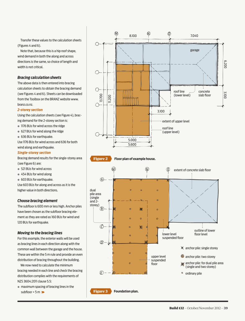
Figure 2
Figure 3
Floor plan of example house.
Foundation plan.
Build 132 — October/November 2012 — 39
Transfer these values to the calculation sheets
(Figures 4 and 6).
Note that, because this is a hip roof shape,
wind demand in both the along and across
directions is the same, so choice of length and
width is not critical.
Bracing calculation sheetsThe above data is then entered into bracing
calculation sheets to obtain the bracing demand
(see Figures 4 and 6). Sheets can be downloaded
from the Toolbox on the BRANZ website www.
branz.co.nz.
2-storey section
Using the calculation sheets (see Figure 4), brac-
ing demand for the 2-storey section is:
● 1176 BUs for wind across the ridge
● 627 BUs for wind along the ridge
● 636 BUs for earthquake.
Use 1176 BUs for wind across and 636 for both
wind along and earthquake.
Single-storey section
Bracing demand results for the single-storey area
(see Figure 6) are:
● 521 BUs for wind across
● 454 BUs for wind along
● 603 BUs for earthquake.
Use 603 BUs for along and across as it is the
higher value in both directions.
Choose bracing elementThe subfloor is 600 mm or less high. Anchor piles
have been chosen as the subfloor bracing ele-
ment as they are rated as 160 BUs for wind and
120 BUs for earthquake.
Moving to the bracing linesFor this example, the exterior walls will be used
as bracing lines in each direction along with the
common wall between the garage and the house.
These are within the 5 m rule and provide an even
distribution of bracing throughout the building.
We now need to calculate the minimum
bracing needed in each line and check the bracing
distribution complies with the requirements of
NZS 3604:2011 clause 5.5:
● maximum spacing of bracing lines in the
subfloor = 5 m
6.200
3.100
8.100 7.040
3.100
5.0005.600
13.7
00
11.2
00
M N 0
garage
concrete slab floor
roof line (lower level)
roof line (upper level)
extent of upper level
M N 0
A
B
C
D
E
upper level suspended floor
lower level suspended floor
extent of concrete slab floor
outline of lower floor level
dual pile area (single and 2- storey)
anchor pile: single storey
anchor pile: two storey
anchor pile: for dual pile area (single and two storey)
ordinary pile

Note
40 — Build 132 — October/November 2012
plate on the lowest floor to the top of the roof).
In this example, width 5 m × 1.7 = 8.5 m, so this
design is OK as the height is 6.5 m from underside
of bottom plate to top of roof.
There is also a minimum number of subfloor
braces (NZS 3604:2011 clause 5.5.6) – a
minimum of four braced or anchor piles placed
in each direction symmetrically around the
perimeter. Wherever practical, they should be
placed near a corner. This design has five piles
in the across direction and nine in the along
direction so is OK.
Having trouble reading Figures
4–7? You can download these with this
article from www.branz.co.nz/welcome_to_
build then Design Right.
● minimum capacity of subfloor bracing lines is
the greater of:
• 100 BUs
• 15 BU/m of bracing line
• 50% of the total bracing demand, divided
by the number of bracing lines in the
direction being considered.
See Table 1 where this has been worked through.
Minimum bracing for 2-storey section
Using the calculation sheet (see Figure 5)
gives:
● 1280 BUs for wind across
● 960 BUs for earthquake and along.
This meets the minimum demand requirements
from the calculation sheet (see Figure 4) and
NZS 3604:2011 clause 5.5.2.
Minimum bracing for single-storey section
Using the calculation sheet (see Figure 7) gives:
● 1080 BUs for earthquake bracing across
● 1080 BUs for earthquake bracing along.
This meets the minimum demand requirements
from the calculation sheet (see Figure 6) and
NZS 3604 clause 5.5.2.
The piles in brace line N are staggered to
comply with the requirement that braced or load-
bearing walls are within 200 mm of the pile line.
More to checkBuildings where the height exceeds 1.7 times
the width must be on a continuous foundation
wall (NZS 3604:2011 clause 5.4.3.2). Height is
measured from the underside of the bottom
Figure 4 Figure 5Calculation sheet for demand – 2-storey section of subfloor.
Calculation sheet for bracing achieved – 2-storey section of subfloor.

Build 132 — October/November 2012 — 41
MINIMUM BRACING NEEDED IN EACH LINETable 1
2-STOREY SECTION SINGLE-STOREY SECTION
WIND ACROSS RIDGE
Bracing lines B, C, D and E = 5 m long A, B, C, D = 8.1 m long
Bracing demand per line (greatest value)
100 BUs or 75 BUs (5.0 x 15 BUs) or 147 BUs (1176 BUs divided by 2 = 588 divided by 4 lines)
100 BUs or 122 BUs (8.1 x 15) or 76 BUs (603 BUs divided by 2 = 301.5 divided by 4 lines)
Minimum BUs per line 147 BUs 122 BUs
Minimum anchor piles per line 1 anchor pile = 160 BUs (wind) 2 anchor piles = 240 BUs (120 each for earthquake)
WIND ALONG RIDGE
Bracing lines M and N = 10.6 m long M, N, O = 9.3 m long
Bracing demand per line (greater value)
100 BUs or159 BUs (10.6 x 15) or159 BUs (636 BUs (for earthquake) divided by 2 = 318 divided by 2 lines)
100 BUs or 140 BUs (9.3 x 15) or100 BUs (603 BUs divided by 2 = 301.5 divided by 3 lines)
Minimum BUs per line 159 BUs 140 BUs
Minimum piles per line 2 anchor piles = 240 BUs (120 each for earthquake) 2 anchor piles = 240 BUs (120 each for earthquake)
Figure 6 Calculation sheet for demand – single-storey section of subfloor.
Figure 7 Calculation sheet for bracing achieved – single-storey section of subfloor.


