calculating a slide sheet
TRANSCRIPT
HOW TO CALCULATE A SLIDE SHEET
One of the most important pieces of equipment to a directional driller is the slide sheet. The slide sheet provides a written record of all down hole orientation. It also allows the directional driller to accurately project to the bit through mathematical calculations. The slide sheet also allows others drilling future wells what was done, and motor output for a given well.
The following is an explanation of how a slide sheet works, as well as what is recorded, and the formulas required to make the calculations. Each step in completing the slide sheet will be described and labeled in great detail. All the information for the well is listed below. In each step, rows, columns, and cells have been identified in order to aid in descriptions. Each cell in the slide sheet will be identified first by the row number followed by the column number. As an example, cell 1D represents the box in the first row under column D. In helping describe how the slide sheet is filled out, each row will be discussed in full detail, and described in sequential order.
The slide sheet used in this example is the same as what is printed off in the First Program. The only difference between the two is one column is changed. In the First version of the slide sheet, a column is there for motor setting. Since this can not be changed down hole, it a column that is not used. For instructional purposes, the inclination at the bit will be recorded in this column.
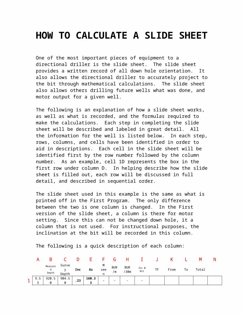
The following is a quick description of each column:
A B C D E F G H I J K L M NMeasured
DepthSurveyDepth
Inc AzM
seenBUR/m
BUR/30m
Inc @ Bit TF From To Total
1 9.53 920.50 904.50 .23 160.33 - - - -
Column A: The length of each pipe/heviwaite to be used. Column B: The Depth at which the bit is located. Includes all tools and pipe. Column C: The depth at which the survey is taken (generally 15 – 19 meters back
from the bit. Column D: The inclination that is recorded at the survey depth not bit depth. Column E: The azimuth that is recorded at the survey depth, again, not bit depth. Column F: A total of how many meters of slide that are seen between the last
survey and the present survey Column G: This is the calculated rate at which the motor is building, calculated
on a per meter basis. Column H: This is the calculated rate at which the motor is building, calculated
on a per 30 meter basis.

Column I: This is the calculated inclination at the bit. It is used further in well planning.
Column J: This is the direction at which a slide was made. Can be either a magnetic or gravity tool face.
Column K: The depth at which the slide began is recorded in this box. Column L: The depth at which the slide finishes is recorded in this box. Column M: The number of meters that were slide is recorded in this box. Column N: A blank column that will assist us in helping separate amounts of
slide according to survey stations (this will be explained in greater depth later on).
For this example, all well information is listed below.
Well Information
Motor: Commander 6 ¾ LN7830Hole Size: 216mmBuild Rate: 10°/30 metersKick Off Point: 920 metersTermination Angle: 90Proposed Azimuth: 160° True NorthMotor Setting: 1.83°
Row # 1
Starting The Kick Off
You get drilled down to the kick off point of 920 meters. It happens to work out that the kick off point is on a connection. Keeping things simple, it is decided to kick off the well at the connection depth. It is important to keep good notes and good slide sheets. In build sections or wells with high angle build rates, a survey should be taken at every connection. Once the survey is taken, the inclination and azimuth is recorded in the appropriate columns (columns D & E).
A B C D E F G H I J K L M NMeasured
DepthSurveyDepth
Inc AzM
seenBUR/m
BUR/30m
Inc @ Bit TF From To Total
1 9.53 920.50 904.50 .23 160.33 - - - -
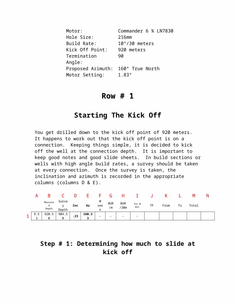
Step # 1: Determining how much to slide at kick off
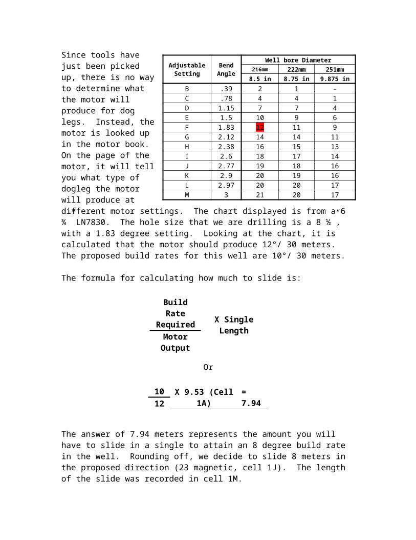
Since tools have just been picked up, there is no way to determine what the motor will produce for dog legs. Instead, the motor is looked up in the motor book. On the page of the motor, it will tell you what type of dogleg the motor will produce at different motor settings. The chart displayed is from a 6 ¾” LN7830. The hole size that we are drilling is a 8 ½”, with a 1.83 degree setting. Looking at the chart, it is calculated that the motor should produce 12°/ 30 meters. The proposed build rates for this well are 10°/ 30 meters.
The formula for calculating how much to slide is:
Or
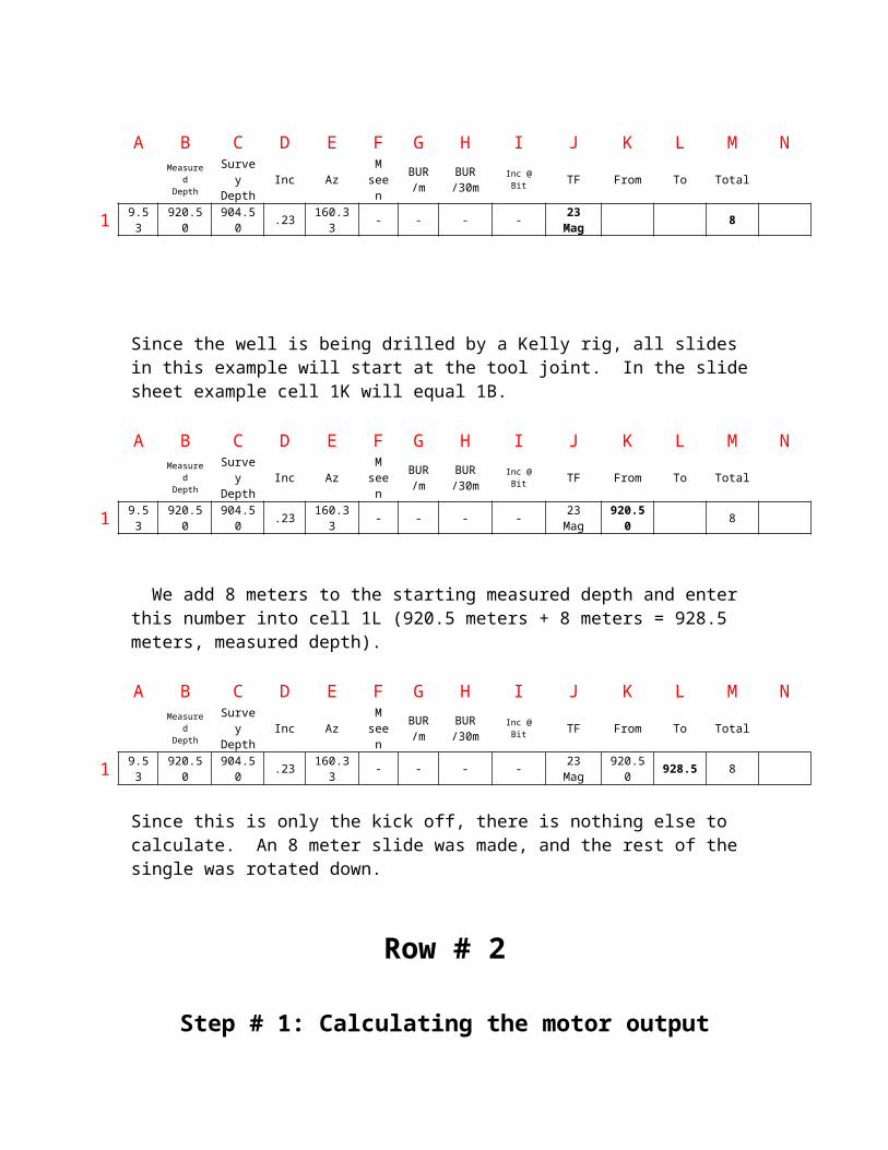
The answer of 7.94 meters represents the amount you will have to slide in a single to attain an 8 degree build rate in the well. Rounding off, we decide to slide 8 meters in the proposed direction (23 magnetic, cell 1J). The length of the slide was recorded in cell 1M.
A B C D E F G H I J K L M NMeasured
DepthSurveyDepth
Inc AzM
seenBUR/m
BUR/30m
Inc @ Bit TF From To Total
1 9.53 920.50 904.50 .23 160.33 - - - - 23 Mag 8
AdjustableSetting
BendAngle
Well bore Diameter216mm 222mm 251mm8.5 in 8.75 in 9.875 in
B .39 2 1 -C .78 4 4 1D 1.15 7 7 4E 1.5 10 9 6F 1.83 12 11 9G 2.12 14 14 11H 2.38 16 15 13I 2.6 18 17 14J 2.77 19 18 16K 2.9 20 19 16L 2.97 20 20 17M 3 21 20 17
Build Rate Required
X Single LengthMotor Output
10X 9.53 (Cell 1A) = 7.94
12
Since the well is being drilled by a Kelly rig, all slides in this example will start at the tool joint. In the slide sheet example cell 1K will equal 1B.
A B C D E F G H I J K L M NMeasured
DepthSurveyDepth
Inc AzM
seenBUR/m
BUR/30m
Inc @ Bit TF From To Total
1 9.53 920.50 904.50 .23 160.33 - - - - 23 Mag 920.50 8
We add 8 meters to the starting measured depth and enter this number into cell 1L (920.5 meters + 8 meters = 928.5 meters, measured depth).
A B C D E F G H I J K L M NMeasured
DepthSurveyDepth
Inc AzM
seenBUR/m
BUR/30m
Inc @ Bit TF From To Total
1 9.53 920.50 904.50 .23 160.33 - - - - 23 Mag 920.50 928.5 8
Since this is only the kick off, there is nothing else to calculate. An 8 meter slide was made, and the rest of the single was rotated down.
Row # 2
Step # 1: Calculating the motor output
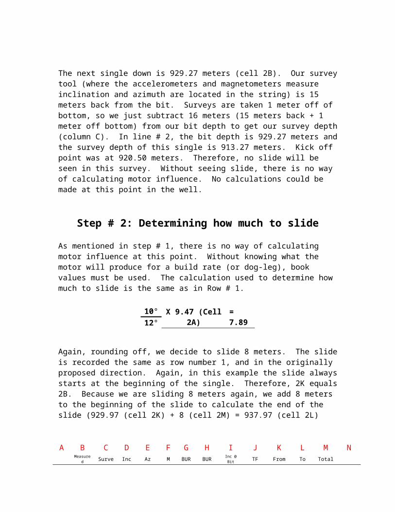
The next single down is 929.27 meters (cell 2B). Our survey tool (where the accelerometers and magnetometers measure inclination and azimuth are located in the string) is 15 meters back from the bit. Surveys are taken 1 meter off of bottom, so we just subtract 16 meters (15 meters back + 1 meter off bottom) from our bit depth to get our survey depth (column C). In line # 2, the bit depth is 929.27 meters and the survey depth of this single is 913.27 meters. Kick off point was at 920.50 meters. Therefore, no slide will be seen in this survey. Without seeing slide, there is no way of calculating motor influence. No calculations could be made at this point in the well.
Step # 2: Determining how much to slide
As mentioned in step # 1, there is no way of calculating motor influence at this point. Without knowing what the motor will produce for a build rate (or dog-leg), book values must be used. The calculation used to determine how much to slide is the same as in Row # 1.
10°X 9.47 (Cell 2A) = 7.89
12°
Again, rounding off, we decide to slide 8 meters. The slide is recorded the same as row number 1, and in the originally proposed direction. Again, in this example the slide always starts at the beginning of the single. Therefore, 2K equals 2B. Because we are sliding 8 meters again, we add 8 meters to the beginning of the slide to calculate the end of the slide (929.97 (cell 2K) + 8 (cell 2M) = 937.97 (cell 2L)
A B C D E F G H I J K L M NMeasured
DepthSurveyDepth
Inc AzM
seenBUR/m
BUR/30m
Inc @ Bit TF From To Total
1 9.53 920.50 904.50 .23 160.33 - - - - 23 Mag 920.50 928.5 8
2 9.47 929.97 913.97 .43 160.67 - - - - 23 Mag 929.97 937.97 8
Row # 3
Step # 1: Calculating slide seen
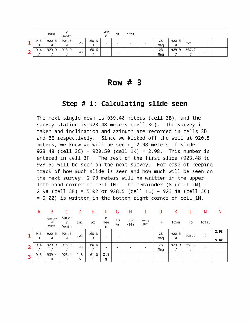
The next single down is 939.48 meters (cell 3B), and the survey station is 923.48 meters (cell 3C). The survey is taken and inclination and azimuth are recorded in cells 3D and 3E respectively. Since we kicked off the well at 920.5 meters, we know we will be seeing 2.98 meters of slide. 923.48 (cell 3C) – 920.50 (cell 1K) = 2.98. This number is entered in cell 3F. The rest of the first slide (923.48 to 928.5) will be seen on the next survey. For ease of keeping track of how much slide is seen and how much will be seen on the next survey, 2.98 meters will be written in the upper left hand corner of cell 1N. The remainder (8 (cell 1M) – 2.98 (cell 3F) = 5.02 or 928.5 (cell 1L) – 923.48 (cell 3C) = 5.02) is written in the bottom right corner of cell 1N.
A B C D E F G H I J K L M NMeasured
DepthSurveyDepth
Inc AzM
seenBUR/m
BUR/30m
Inc @ Bit TF From To Total
1 9.53 920.50 904.50 .23 160.33 - - - - 23 Mag 920.50 928.5 82.98 5.02
2 9.47 929.97 913.97 .43 160.67 - - - - 23 Mag 929.97 937.97 8
3 9.51 939.48 923.48 1.85 161.01 2.98
Step # 2: Calculating the motor output
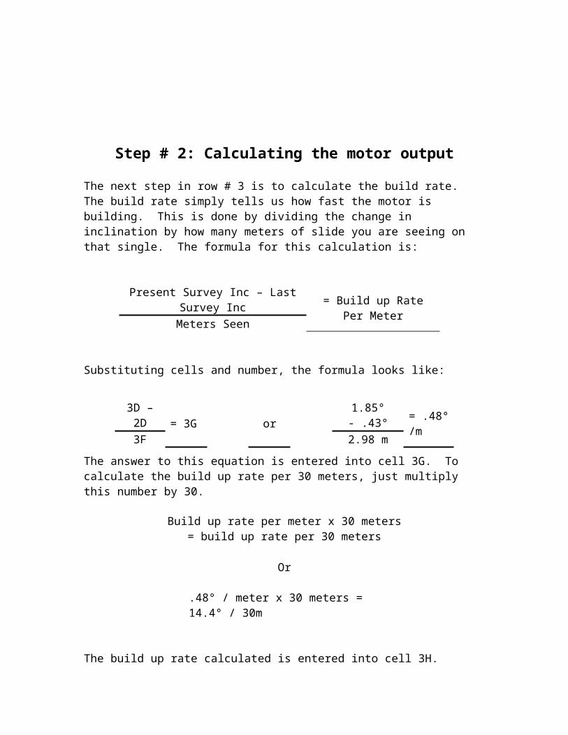
The next step in row # 3 is to calculate the build rate. The build rate simply tells us how fast the motor is building. This is done by dividing the change in inclination by how many meters of slide you are seeing on that single. The formula for this calculation is:
Present Survey Inc – Last Survey Inc= Build up Rate Per Meter
Meters Seen
Substituting cells and number, the formula looks like:
The answer to this equation is entered into cell 3G. To calculate the build up rate per 30 meters, just multiply this number by 30.
Or
.48° / meter x 30 meters = 14.4° / 30m
The build up rate calculated is entered into cell 3H.
A B C D E F G H I J K L M NMeasured
DepthSurveyDepth
Inc AzM
seenBUR/m
BUR/30m
Inc @ Bit TF From To Total
1 9.53 920.50 904.50 .23 160.33 - - - - 23 Mag 920.50 928.5 82.98 5.02
2 9.47 929.97 913.97 .43 160.67 - - - - 23 Mag 929.97 937.97 8
3 9.51 939.48 923.48 1.85 161.01 2.98 .48 14.4
Step # 3: Calculating the inclination at the bit
We have now calculated your motor out-put, it is time to calculate what the inclination is at the bit. ALL PROJECTIONS HAVE TO BE FROM THE BIT! Failing to do so could result in crashing a well. If a motor is not producing enough build, it is easily caught and the slide ratio can be increased compensating for the low build rates. If you are drilling
3D – 2D= 3G or
1.85° - .43°= .48°/m
3F 2.98 m
Build up rate per meter x 30 meters = build up rate per 30 meters
from the survey station, by the time you see the low build rates, the bit’s inclination would require drastic measures to compensate in order to save the well.
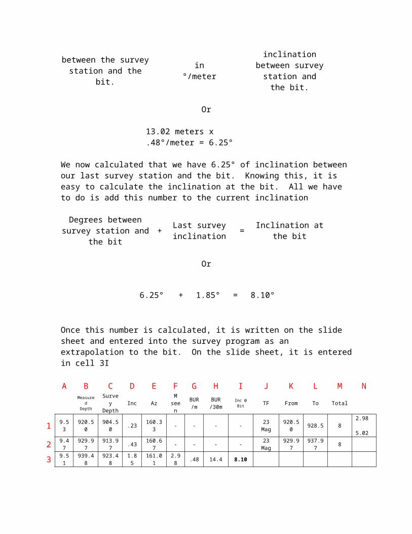
In Step # 2 we were able to calculate the build rate based on the amount of influence the 2.98 meters of slide had upon our inclination. Now we are going to calculate what the inclination is going to be at the bit using the same amount of influence. Looking at cell 1N we know there was 5.02 meters of slide that we have not yet seen. In addition to that, we know we have not yet seen the 8 meters of slide on the second single (cell 2M). The total meters of slide not yet seen would be 5.02 (cell 1N) + 8 (cell 2M) = 13.02 meters of slide not yet seen. We know what the build rate is for this single (.48°/meter (cell 3G)). All we have to do is multiply them together and we will get:
Meters of slide between the survey station and the
bit.x
Motor output in°/meter
=
Degrees of inclination between survey station and
the bit.
Or
13.02 meters x .48°/meter = 6.25°
We now calculated that we have 6.25° of inclination between our last survey station and the bit. Knowing this, it is easy to calculate the inclination at the bit. All we have to do is add this number to the current inclination
Degrees between survey station and the bit
+Last survey inclination
= Inclination at the bit
Or
Once this number is calculated, it is written on the slide sheet and entered into the survey program as an extrapolation to the bit. On the slide sheet, it is entered in cell 3I
A B C D E F G H I J K L M NMeasured
DepthSurveyDepth
Inc AzM
seenBUR/m
BUR/30m
Inc @ Bit TF From To Total
1 9.53 920.50 904.50 .23 160.33 - - - - 23 Mag 920.50 928.5 82.98 5.02
2 9.47 929.97 913.97 .43 160.67 - - - - 23 Mag 929.97 937.97 8
3 9.51 939.48 923.48 1.85 161.01 2.98 .48 14.4 8.10
6.25° + 1.85° = 8.10°
Step # 4: Determining how much to slide
Determining how many meters to slide is the same in all rows. If you are looking for the formulas, look back at Row # 1, Step # 1. The only difference at this point is that we are starting to see how fast the motor is actually building. The same formula is used as in rows 1 and 2, but this time we will be influenced by the motor output calculated in row # 3. Using a survey program or hand calculations, you calculate what is required for a build rate to the target (calculating the build rate to the target is covered in well planning and not calculating a slide sheet). After the well planning is complete, a build rate of 9.90°/30 is required in order to hit the target. The motor output at this point in time is 14.4°/30 meters (calculated in row 3). However, this is the first slide in the well and at times could be greater that what the motor puts out normally. For this reason instead of using a 14.4 for motor output, we are going to use 13°/30. This is based on a general average between the book value and the actual motor output (12°/30 book value, and the motor output of 14.4°/30). The amount we are going to slide is:
Sliding on the side of caution, we decide to slide 7.5 meters on this single. As described earlier, the slide information is properly entered.
A B C D E F G H I J K L M NMeasured
DepthSurveyDepth
Inc AzM
seenBUR/m
BUR/30m
Inc @ Bit TF From To Total
1 9.53 920.50 904.50 .23 160.33 - - - - 23 Mag 920.50 928.5 82.98 5.02
2 9.47 929.97 913.97 .43 160.67 - - - - 23 Mag 929.97 937.97 8
3 9.51 939.48 923.48 1.85 161.01 2.98 .48 14.4 8.10 23 Mag 939.48 946.98 7.5
Row # 4
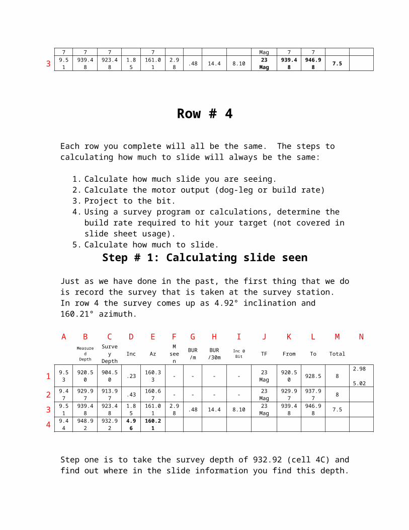
Each row you complete will all be the same. The steps to calculating how much to slide will always be the same:
1. Calculate how much slide you are seeing.2. Calculate the motor output (dog-leg or build rate)3. Project to the bit.4. Using a survey program or calculations, determine the build rate required to hit
your target (not covered in slide sheet usage).
9.9°X 9.51 (Cell 3A) = 7.24 meters
13°

5. Calculate how much to slide.
Step # 1: Calculating slide seen
Just as we have done in the past, the first thing that we do is record the survey that is taken at the survey station. In row 4 the survey comes up as 4.92° inclination and 160.21° azimuth.
A B C D E F G H I J K L M NMeasured
DepthSurveyDepth
Inc AzM
seenBUR/m
BUR/30m
Inc @ Bit TF From To Total
1 9.53 920.50 904.50 .23 160.33 - - - - 23 Mag 920.50 928.5 82.98 5.02
2 9.47 929.97 913.97 .43 160.67 - - - - 23 Mag 929.97 937.97 8
3 9.51 939.48 923.48 1.85 161.01 2.98 .48 14.4 8.10 23 Mag 939.48 946.98 7.5
4 9.44 948.92 932.92 4.96 160.21
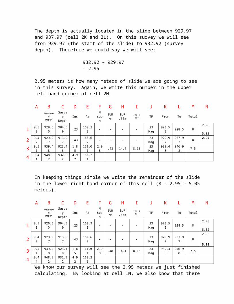
Step one is to take the survey depth of 932.92 (cell 4C) and find out where in the slide information you find this depth. The depth is actually located in the slide between 929.97 and 937.97 (cell 2K and 2L). On this survey we will see from 929.97 (the start of the slide) to 932.92 (survey depth). Therefore we could say we will see:
932.92 – 929.97 = 2.95
2.95 meters is how many meters of slide we are going to see in this survey. Again, we write this number in the upper left hand corner of cell 2N.
A B C D E F G H I J K L M NMeasured
DepthSurveyDepth
Inc AzM
seenBUR/m
BUR/30m
Inc @ Bit TF From To Total
1 9.53 920.50 904.50 .23 160.33 - - - - 23 Mag 920.50 928.5 82.98 5.02
2 9.47 929.97 913.97 .43 160.67 - - - - 23 Mag 929.97 937.97 82.95
3 9.51 939.48 923.48 1.85 161.01 2.98 .48 14.4 8.10 23 Mag 939.48 946.98 7.5
4 9.44 948.92 932.92 4.92 160.21
In keeping things simple we write the remainder of the slide in the lower right hand corner of this cell (8 – 2.95 = 5.05 meters).
A B C D E F G H I J K L M NMeasured
DepthSurveyDepth
Inc AzM
seenBUR/m
BUR/30m
Inc @ Bit TF From To Total
1 9.53 920.50 904.50 .23 160.33 - - - - 23 Mag 920.50 928.5 82.98 5.02
2 9.47 929.97 913.97 .43 160.67 - - - - 23 Mag 929.97 937.97 82.95 5.05
3 9.51 939.48 923.48 1.85 161.01 2.98 .48 14.4 8.10 23 Mag 939.48 946.98 7.5
4 9.44 948.92 932.92 4.92 160.21
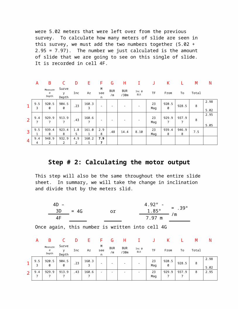
We know our survey will see the 2.95 meters we just finished calculating. By looking at cell 1N, we also know that there were 5.02 meters that were left over from the previous survey. To calculate how many meters of slide are seen in this survey, we must add the two numbers together (5.02 + 2.95 = 7.97). The number we just calculated is the amount of slide that we are going to see on this single of slide. It is recorded in cell 4F.
A B C D E F G H I J K L M NMeasured
DepthSurveyDepth
Inc AzM
seenBUR/m
BUR/30m
Inc @ Bit TF From To Total
1 9.53 920.50 904.50 .23 160.33 - - - - 23 Mag 920.50 928.5 82.98 5.02
2 9.47 929.97 913.97 .43 160.67 - - - - 23 Mag 929.97 937.97 82.95 5.05
3 9.51 939.48 923.48 1.85 161.01 2.98 .48 14.4 8.10 23 Mag 939.48 946.98 7.5
4 9.44 948.92 932.92 4.92 160.21 7.97
Step # 2: Calculating the motor output
This step will also be the same throughout the entire slide sheet. In summary, we will take the change in inclination and divide that by the meters slid.
Once again, this number is written into cell 4G
A B C D E F G H I J K L M NMeasured
DepthSurveyDepth
Inc AzM
seenBUR/m
BUR/30m
Inc @ Bit TF From To Total
1 9.53 920.50 904.50 .23 160.33 - - - - 23 Mag 920.50 928.5 82.98 5.02
2 9.47 929.97 913.97 .43 160.67 - - - - 23 Mag 929.97 937.97 82.95 5.05
3 9.51 939.48 923.48 1.85 161.01 2.98 .48 14.4 8.10 23 Mag 939.48 946.98 7.5
4 9.44 948.92 932.92 4.92 160.21 7.97 .39
4D – 3D= 4G or
4.92° - 1.85°= .39°/m
4F 7.97 m

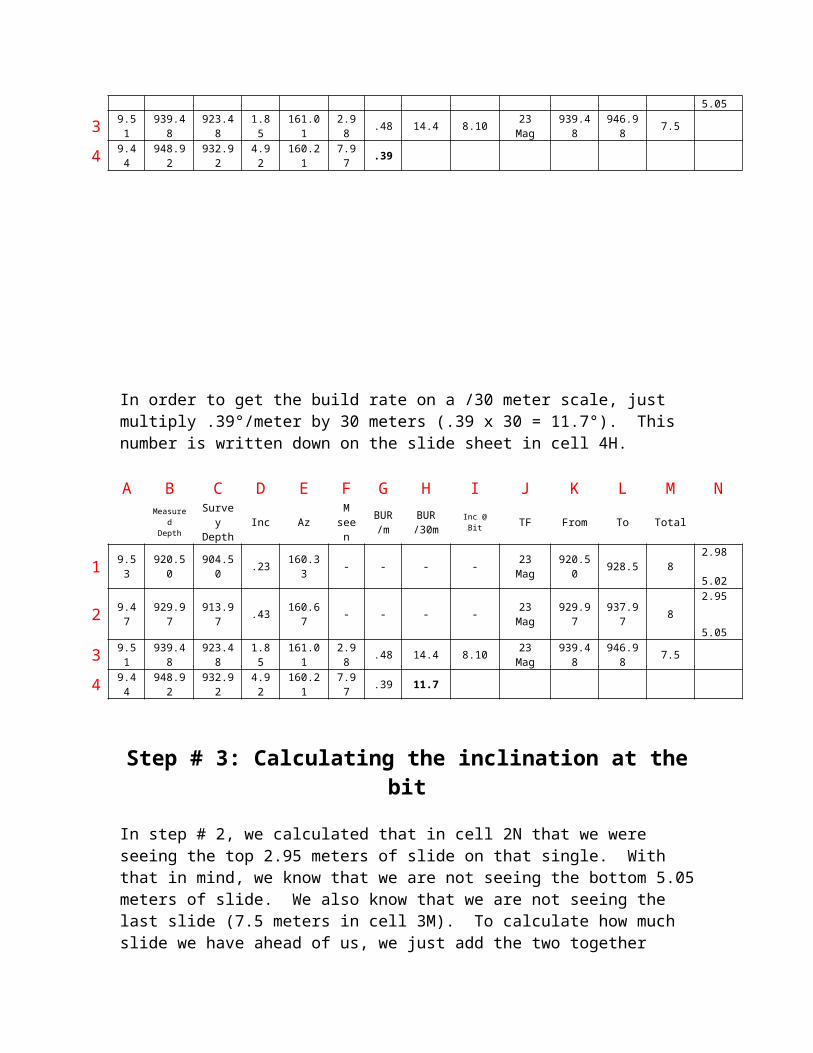
In order to get the build rate on a /30 meter scale, just multiply .39°/meter by 30 meters (.39 x 30 = 11.7°). This number is written down on the slide sheet in cell 4H.
A B C D E F G H I J K L M NMeasured
DepthSurveyDepth
Inc AzM
seenBUR/m
BUR/30m
Inc @ Bit TF From To Total
1 9.53 920.50 904.50 .23 160.33 - - - - 23 Mag 920.50 928.5 82.98 5.02
2 9.47 929.97 913.97 .43 160.67 - - - - 23 Mag 929.97 937.97 82.95 5.05
3 9.51 939.48 923.48 1.85 161.01 2.98 .48 14.4 8.10 23 Mag 939.48 946.98 7.5
4 9.44 948.92 932.92 4.92 160.21 7.97 .39 11.7
Step # 3: Calculating the inclination at the bit
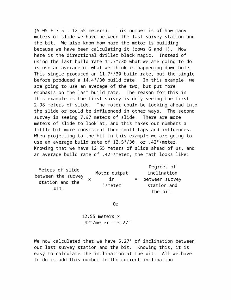
In step # 2, we calculated that in cell 2N that we were seeing the top 2.95 meters of slide on that single. With that in mind, we know that we are not seeing the bottom 5.05 meters of slide. We also know that we are not seeing the last slide (7.5 meters in cell 3M). To calculate how much slide we have ahead of us, we just add the two together (5.05 + 7.5 = 12.55 meters). This number is of how many meters of slide we have between the last survey station and the bit. We also know how hard the motor is building because we have been calculating it (rows G and H). Now here is the directional driller black magic. Instead of using the last build rate 11.7°/30 what we are going to do is use an average of what we think is happening down hole. This single produced an 11.7°/30 build rate, but the single before produced a 14.4°/30 build rate. In this example, we are going to use an average of the two, but put more emphasis on the last build rate. The reason for this in this example is the first survey is only seeing the first 2.98 meters of slide. The motor could be looking ahead into the slide or could be influenced in other ways. The second survey is seeing 7.97 meters of slide. There are more meters of slide to look at, and this makes our numbers a little bit more consistent then small taps and influences. When projecting to the bit in this example we are going to use an average build rate of 12.5°/30, or .42°/meter. Knowing that we have 12.55 meters of slide ahead of us, and an average build rate of .42°/meter, the math looks like:
Meters of slide between the survey station and the
bit.x
Motor output in°/meter
=
Degrees of inclination between survey station and
the bit.
Or
12.55 meters x .42°/meter = 5.27°
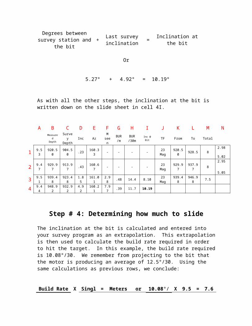
We now calculated that we have 5.27° of inclination between our last survey station and the bit. Knowing this, it is easy to calculate the inclination at the bit. All we have to do is add this number to the current inclination
Degrees between survey station and the bit
+Last survey inclination
= Inclination at the bit
Or
As with all the other steps, the inclination at the bit is written down on the slide sheet in cell 4I.
A B C D E F G H I J K L M NMeasured
DepthSurveyDepth
Inc AzM
seenBUR/m
BUR/30m
Inc @ Bit TF From To Total
1 9.53 920.50 904.50 .23 160.33 - - - - 23 Mag 920.50 928.5 82.98 5.02
2 9.47 929.97 913.97 .43 160.67 - - - - 23 Mag 929.97 937.97 82.95 5.05
3 9.51 939.48 923.48 1.85 161.01 2.98 .48 14.4 8.10 23 Mag 939.48 946.98 7.5
4 9.44 948.92 932.92 4.92 160.21 7.97 .39 11.7 10.19
Step # 4: Determining how much to slide
The inclination at the bit is calculated and entered into your survey program as an extrapolation. This extrapolation is then used to calculate the build rate required in order to hit the target. In this example, the build rate required is 10.08°/30. We remember from projecting to the bit that the motor is producing an average of 12.5°/30. Using the same calculations as previous rows, we conclude:
Build Rate Required X
SingleLength
=Meters
Required To Slide
or10.08°/30
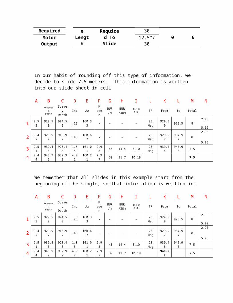
X 9.50 = 7.66Motor Output 12.5°/30
In our habit of rounding off this type of information, we decide to slide 7.5 meters. This information is written into our slide sheet in cell
5.27° + 4.92° = 10.19°
A B C D E F G H I J K L M NMeasured
DepthSurveyDepth
Inc AzM
seenBUR/m
BUR/30m
Inc @ Bit TF From To Total
1 9.53 920.50 904.50 .23 160.33 - - - - 23 Mag 920.50 928.5 82.98 5.02
2 9.47 929.97 913.97 .43 160.67 - - - - 23 Mag 929.97 937.97 82.95 5.05
3 9.51 939.48 923.48 1.85 161.01 2.98 .48 14.4 8.10 23 Mag 939.48 946.98 7.5
4 9.44 948.92 932.92 4.92 160.21 7.97 .39 11.7 10.19 7.5
We remember that all slides in this example start from the beginning of the single, so that information is written in:
A B C D E F G H I J K L M NMeasured
DepthSurveyDepth
Inc AzM
seenBUR/m
BUR/30m
Inc @ Bit TF From To Total
1 9.53 920.50 904.50 .23 160.33 - - - - 23 Mag 920.50 928.5 82.98 5.02
2 9.47 929.97 913.97 .43 160.67 - - - - 23 Mag 929.97 937.97 82.95 5.05
3 9.51 939.48 923.48 1.85 161.01 2.98 .48 14.4 8.10 23 Mag 939.48 946.98 7.5
4 9.44 948.92 932.92 4.92 160.21 7.97 .39 11.7 10.19 948.92 7.5
We add the single length to where we started, and come up with:
A B C D E F G H I J K L M NMeasured
DepthSurveyDepth
Inc AzM
seenBUR/m
BUR/30m
Inc @ Bit TF From To Total
1 9.53 920.50 904.50 .23 160.33 - - - - 23 Mag 920.50 928.5 82.98 5.02
2 9.47 929.97 913.97 .43 160.67 - - - - 23 Mag 929.97 937.97 82.95 5.05
3 9.51 939.48 923.48 1.85 161.01 2.98 .48 14.4 8.10 23 Mag 939.48 946.98 7.5
4 9.44 948.92 932.92 4.92 160.21 7.97 .39 11.7 10.19 948.92 956.42 7.5
Because are proposed direction is 160° azimuth, and we are heading directly in that direction we are going to keep sliding in that direction. However, in both pulse tools and EM tools, our tool face is going to switch from a magnetic tool face to a gravity tool face. Now instead of sliding in a direction related to magnetic north, we are now going to slide in a direction in relation to gravity. Since we want to keep building inclination, we are going to slide in a high side (HS) tool face (or straight up). If we wanted to turn the well slightly to the right, we could be sliding at a 20R tool face. If we wanted to turn the well slightly to the left, we could be sliding at a 20L tool face. This tool face is recorded in the slide sheet.
A B C D E F G H I J K L M N
MeasuredDepth
SurveyDepth
Inc AzM
seenBUR/m
BUR/30m
Inc @ Bit TF From To Total
1 9.53 920.50 904.50 .23 160.33 - - - - 23 Mag 920.50 928.5 82.98 5.02
2 9.47 929.97 913.97 .43 160.67 - - - 3.63 23 Mag 929.97 937.97 82.95 5.05
3 9.51 939.48 923.48 1.85 161.01 2.98 .48 14.4 8.10 23 Mag 939.48 946.98 7.5
4 9.44 948.92 932.92 4.92 160.21 7.97 .39 11.7 10.19 HS 948.92 956.42 7.5
Row # 5
By this point in time, you should be able to figure out most of the calculations, and we can move fairly quickly through this row. The survey comes up as 7.84° inclination, and an azimuth of 159.88°. These numbers are written in the slide sheet, and the calculations begin.
Step # 1: Calculating slide seen
The survey at 942.42 meters falls between the slide from 939.48 to 946.98 meters (cells 3K to 3L). 942.42 – 939.48 = 2.94. This is written in the upper left hand corner of 3N.
A B C D E F G H I J K L M NMeasured
DepthSurveyDepth
Inc AzM
seenBUR/m
BUR/30m
Inc @ Bit TF From To Total
1 9.53 920.50 904.50 .23 160.33 - - - - 23 Mag 920.50 928.5 82.98 5.02
2 9.47 929.97 913.97 .43 160.67 - - - 3.63 23 Mag 929.97 937.97 82.95 5.05
3 9.51 939.48 923.48 1.85 161.01 2.98 .48 14.4 8.10 23 Mag 939.48 946.98 7.52.94
4 9.44 948.92 932.92 4.96 160.21 7.97 .39 11.7 10.19 HS 948.92 956.42 7.5
5 9.50 958.42 942.42 7.84 159.88
This 2.94 meters is subtracted off of the amount slide in this row (7.5 meters), and is written in the bottom right hand corner (7.5 – 2.94 = 4.56).
A B C D E F G H I J K L M NMeasured
DepthSurveyDepth
Inc AzM
seenBUR/m
BUR/30m
Inc @ Bit TF From To Total
1 9.53 920.50 904.50 .23 160.33 - - - - 23 Mag 920.50 928.5 82.98 5.02
2 9.47 929.97 913.97 .43 160.67 - - - 3.63 23 Mag 929.97 937.97 82.95 5.05
3 9.51 939.48 923.48 1.85 161.01 2.98 .48 14.4 8.10 23 Mag 939.48 946.98 7.52.94 4.56
4 9.44 948.92 932.92 4.96 160.21 7.97 .39 11.7 10.19 HS 948.92 956.42 7.5
5 9.50 958.42 942.42 7.84 159.88
In this row, we know we are going to see the 2.94 meters (cell 3N), plus what was left over from the previous slide (5.05 meters in cell 2N). Added together we come up with 2.94 + 5.05 = 7.99 meters. This is written down.
A B C D E F G H I J K L M NMeasured
DepthSurveyDepth
Inc AzM
seenBUR/m
BUR/30m
Inc @ Bit TF From To Total
1 9.53 920.50 904.50 .23 160.33 - - - - 23 Mag 920.50 928.5 82.98 5.02
2 9.47 929.97 913.97 .43 160.67 - - - 3.63 23 Mag 929.97 937.97 82.95 5.05
3 9.51 939.48 923.48 1.85 161.01 2.98 .48 14.4 8.10 23 Mag 939.48 946.98 7.52.94 4.56
4 9.44 948.92 932.92 4.96 160.21 7.97 .39 11.7 10.19 HS 948.92 956.42 7.5
5 9.50 958.42 942.42 7.84 159.88 7.99
Step # 2: Calculating the motor output
Using the formula, we calculate:
This is filled in:A B C D E F G H I J K L M N
MeasuredDepth
SurveyDepth
Inc AzM
seenBUR/m
BUR/30m
Inc @ Bit TF From To Total
1 9.53 920.50 904.50 .23 160.33 - - - - 23 Mag 920.50 928.5 82.98 5.02
2 9.47 929.97 913.97 .43 160.67 - - - 3.63 23 Mag 929.97 937.97 82.95 5.05
3 9.51 939.48 923.48 1.85 161.01 2.98 .48 14.4 8.10 23 Mag 939.48 946.98 7.52.94 4.56
4 9.44 948.92 932.92 4.96 160.21 7.97 .39 11.7 10.19 HS 948.92 956.42 7.5
5 9.50 958.42 942.42 7.84 159.88 7.99 .36
We times our build rate per meter by 30 to get our build rate per 30 (.36 x 30) = 10.8°/30 meters. This is filled into the slide sheet:
A B C D E F G H I J K L M N
5D – 4D= 5G or
7.84° - 4.96°= .36°/m
5F 7.99 m
MeasuredDepth
SurveyDepth
Inc AzM
seenBUR/m
BUR/30m
Inc @ Bit TF From To Total
1 9.53 920.50 904.50 .23 160.33 - - - - 23 Mag 920.50 928.5 82.98 5.02
2 9.47 929.97 913.97 .43 160.67 - - - 3.63 23 Mag 929.97 937.97 82.95 5.05
3 9.51 939.48 923.48 1.85 161.01 2.98 .48 14.4 8.10 23 Mag 939.48 946.98 7.52.94 4.56
4 9.44 948.92 932.92 4.96 160.21 7.97 .39 11.7 10.19 HS 948.92 956.42 7.5
5 9.50 958.42 942.42 7.84 159.88 7.99 .36 10.8
Step # 3: Calculating the inclination at the bit
Knowing that we have seen 2.94 meters of slide (cell 3N) in this slide, we know that there is still 4.56 meters left over that we have not seen. We also know that we did not see the following 7.5 meter slide. Adding these two numbers together will equal how many meters of slide we have between our present survey station and the bit. Adding the two numbers together we come up with 4.56 meters + 7.5 meters = 12.06 meters of slide between our survey station and the bit. Looking at the build rates, it would be an average of about 11°/30 meters or .37°/meter. Multiplying the numbers out, we would get .37°/meter x 12.06 meters = 4.46° between the survey station and the bit. To calculate the inclination at the bit, we add the 4.46° to the present survey of 7.84° and come up with an inclination of 12.3° at the bit. This number is filled out in the slide sheet.
A B C D E F G H I J K L M NMeasured
DepthSurveyDepth
Inc AzM
seenBUR/m
BUR/30m
Inc @ Bit TF From To Total
1 9.53 920.50 904.50 .23 160.33 - - - - 23 Mag 920.50 928.5 82.98 5.02
2 9.47 929.97 913.97 .43 160.67 - - - 3.63 23 Mag 929.97 937.97 82.95 5.05
3 9.51 939.48 923.48 1.85 161.01 2.98 .48 14.4 8.10 23 Mag 939.48 946.98 7.52.94 4.56
4 9.44 948.92 932.92 4.96 160.21 7.97 .39 11.7 10.19 HS 948.92 956.42 7.5
5 9.50 958.42 942.42 7.84 159.88 7.99 .36 10.8 12.3
Step # 4: Determining how much to slide
Once the bit inclination is calculated it is always inserted into the survey program to aid in calculating the build rate required in order to hit the target. In row 5, the build rate required works out to 10.33°/30. We remember from projecting to the bit that the motor is producing an average of 11°/30 or .37°/meter. Using the same calculations as previous rows, we conclude:
Build Rate Required X
SingleLength
=Meters
Required To Slide
or10.33°/30
X 9.51 = 8.93Motor Output 11°/30
In our habit of rounding off this type of information, we decide to slide 9 meters of this single. This amount, as well as the starting depth is filled out in the slide sheet.
A B C D E F G H I J K L M NMeasured
DepthSurveyDepth
Inc AzM
seenBUR/m
BUR/30m
Inc @ Bit TF From To Total
1 9.53 920.50 904.50 .23 160.33 - - - - 23 Mag 920.50 928.5 82.98 5.02
2 9.47 929.97 913.97 .43 160.67 - - - 3.63 23 Mag 929.97 937.97 82.95 5.05
3 9.51 939.48 923.48 1.85 161.01 2.98 .48 14.4 8.10 23 Mag 939.48 946.98 7.52.94 4.56
4 9.44 948.92 932.92 4.96 160.21 7.97 .39 11.7 10.19 HS 948.92 956.42 7.5
5 9.50 958.42 942.42 7.84 159.88 7.99 .36 10.8 12.3 958.42 9
The 9 meters are added to the starting depth, and the end of slide is calculated.
A B C D E F G H I J K L M NMeasured
DepthSurveyDepth
Inc AzM
seenBUR/m
BUR/30m
Inc @ Bit TF From To Total
1 9.53 920.50 904.50 .23 160.33 - - - - 23 Mag 920.50 928.5 82.98 5.02
2 9.47 929.97 913.97 .43 160.67 - - - 3.63 23 Mag 929.97 937.97 82.95 5.05
3 9.51 939.48 923.48 1.85 161.01 2.98 .48 14.4 8.10 23 Mag 939.48 946.98 7.52.94 4.56
4 9.44 948.92 932.92 4.96 160.21 7.97 .39 11.7 10.19 HS 948.92 956.42 7.5
5 9.50 958.42 942.42 7.84 159.88 7.99 .36 10.8 12.3 958.42 967.42 9
Last item! We can safely say that we are heading in the right direction, so we are going to continue to slide at a high side tool face.
A B C D E F G H I J K L M NMeasured
DepthSurveyDepth
Inc AzM
seenBUR/m
BUR/30m
Inc @ Bit TF From To Total
1 9.53 920.50 904.50 .23 160.33 - - - - 23 Mag 920.50 928.5 82.98 5.02
2 9.47 929.97 913.97 .43 160.67 - - - 3.63 23 Mag 929.97 937.97 82.95 5.05
3 9.51 939.48 923.48 1.85 161.01 2.98 .48 14.4 8.10 23 Mag 939.48 946.98 7.52.94 4.56
4 9.44 948.92 932.92 4.96 160.21 7.97 .39 11.7 10.19 HS 948.92 956.42 7.5
5 9.50 958.42 942.42 7.84 159.88 7.99 .36 10.8 12.3 HS 958.42 967.42 9
Slide Sheet Review
We have covered every cell in the slide sheet, and included all formulas that were required in order to complete the slide sheet. There is no magic involved in making these calculations, just judgment calls when it comes to rounding off build rates and anticipating what is happening down hole. No matter what your experience level is, projecting to the bit is a crucial step in finding out where you are and what has to be done in order to hit the target. Hope this helps.