(cairo, egypt, 4-6 december 2017) safeguarding workshop... · in this case, the egyptian...
TRANSCRIPT

AERODROME SAFEGUARDING WORKSHOP
(Cairo, Egypt, 4-6 December 2017)

DEVELOPMENT OF SHARM EL SHEIKHINTERNATIONAL AIRPORT
OBSTACLE LIMITATION SURFACES CONSULTANCY STUDIES

OBSTACLE LIMITATION SURFACES LAYOUT EGYPTIAN CIVIL AVIATION REGULATION
EXISTING & Designed CONFIGURATION

Characterization of the current situation
The existing sharm el sheikh airport consists of :
- Two parallel runway system designated (04L-22R&04R-22L) :4E
-Five aprons and a taxiway system which connects them, as shown in the following
illustration:

CHARACTERIZATION OF THE DESIGNED SITUATION
BY analyses the designed situation of the different elements of the airfield in the existing Sharm El Sheikh Airport, according to the project “Development of Sharm El Sheikh International Airport” it includes :
The new Runway, the associated taxiway’s system (double connection links,
parallel taxiway to the runway, inner taxiway to access to the remote stands, the extension of this to reach the link taxiways to increase the airfield capacity, holding bays, two rapid exit taxiways and all the needed connection taxiways), the remote stands apron, all the related service roads (internal roads, ground handling road to connect the existing and the new airfield in the south,…) and the airside control points and security fencing for all the areas.


Also are included all the related facilities (drainage system, marking and lighting, apron floodlighting, meteorological system,…).
Also, it includes the contact stand apron (front and back of the boarding pier) and all the service roads and control points in the adjacent area of th Terminal Building.
� The new runway includes an Instrumental Precision Approach supported by an ILS for the new 04L runway.
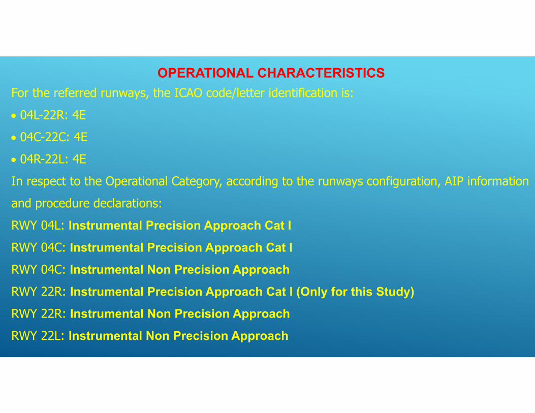
OPERATIONAL CHARACTERISTICSFor the referred runways, the ICAO code/letter identification is: 04L-22R: 4E 04C-22C: 4E 04R-22L: 4EIn respect to the Operational Category, according to the runways configuration, AIP information and procedure declarations:RWY 04L: Instrumental Precision Approach Cat I
RWY 04C: Instrumental Precision Approach Cat I
RWY 04C: Instrumental Non Precision Approach
RWY 22R: Instrumental Precision Approach Cat I (Only for this Study)
RWY 22R: Instrumental Non Precision Approach
RWY 22L: Instrumental Non Precision Approach


According to the previous considerations: the summary of applicable OLS surface, for the SSH systems ,will be:
Related tosurfaceAerodrome OLSApproach surfaceAerodrome OLSTransitional surfaceAerodrome OLSInner horizontal surface
Aerodrome OLSConical surfaceAerodrome OLSOuter horizontal surface
Radio Electric OLSVORRadio Electric OLSVHFRadio Electric OLSRADAR MSSRRadio Electric OLSILS/LLZRadio Electric OLSILS/GP
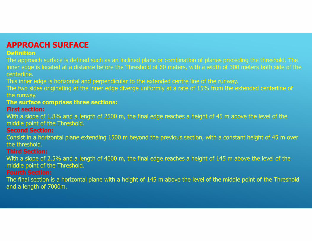
APPROACH SURFACE Definition The approach surface is defined such as an inclined plane or combination of planes preceding the threshold. The inner edge is located at a distance before the Threshold of 60 meters, with a width of 300 meters both side of the centerline. This inner edge is horizontal and perpendicular to the extended centre line of the runway. The two sides originating at the inner edge diverge uniformly at a rate of 15% from the extended centerline of the runway. The surface comprises three sections: First section: With a slope of 1.8% and a length of 2500 m, the final edge reaches a height of 45 m above the level of the middle point of the Threshold. Second Section: Consist in a horizontal plane extending 1500 m beyond the previous section, with a constant height of 45 m over the threshold. Third Section: With a slope of 2.5% and a length of 4000 m, the final edge reaches a height of 145 m above the level of the middle point of the Threshold. Fourth Section: The final section is a horizontal plane with a height of 145 m above the level of the middle point of the Threshold and a length of 7000m.

Approach 04R
Forth sec. Third sec Secondsec.
Firstsec.

Approach 04R

Approach 04C
Forth sec. Third sec. Secondsec.
Firstsec.


Approach 04L
Forth sec. Third sec. Secondsec.
Firstsec.

Approach 04L

Approach 22R
Forth sec.Third sec.Second
sec.Firstsec.

Approach 22R

Approach 22C
Forth sec.Third sec.Secondsec.
Firstsec.

Approach 22C

Approach 22L
Forth sec.Third sec.Second
sec.Firstsec.

Approach 22L

TRANSITIONAL SURFACE 04L/22R
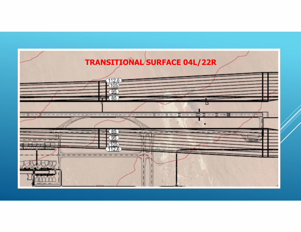
TRANSITIONAL SURFACE 04L/22R

TRANSITIONAL SURFACE 04C/22C
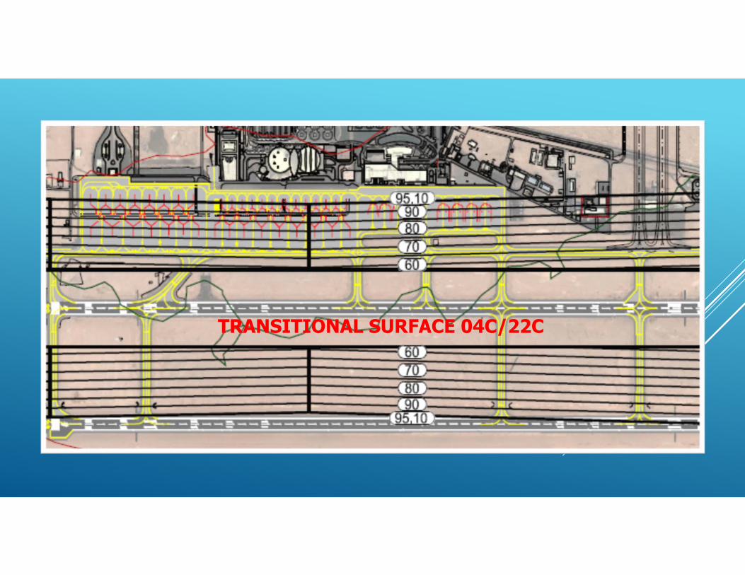
TRANSITIONAL SURFACE 04C/22C
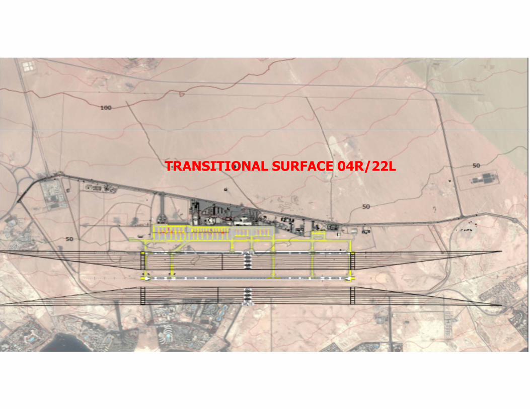
TRANSITIONAL SURFACE 04R/22L

TRANSITIONAL SURFACE 04R/22L

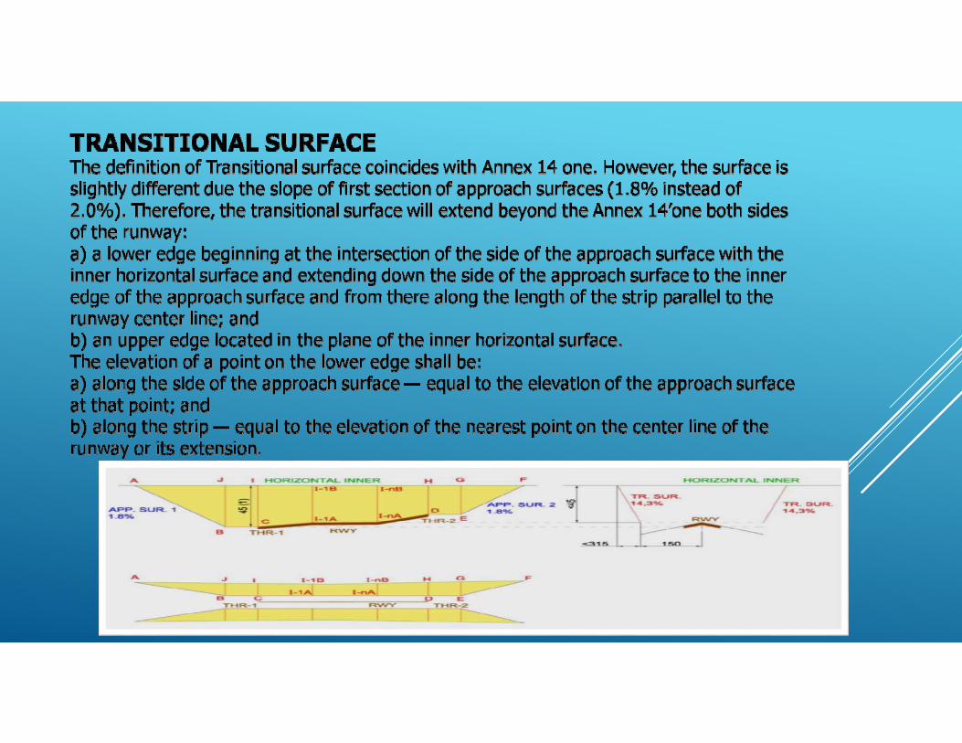
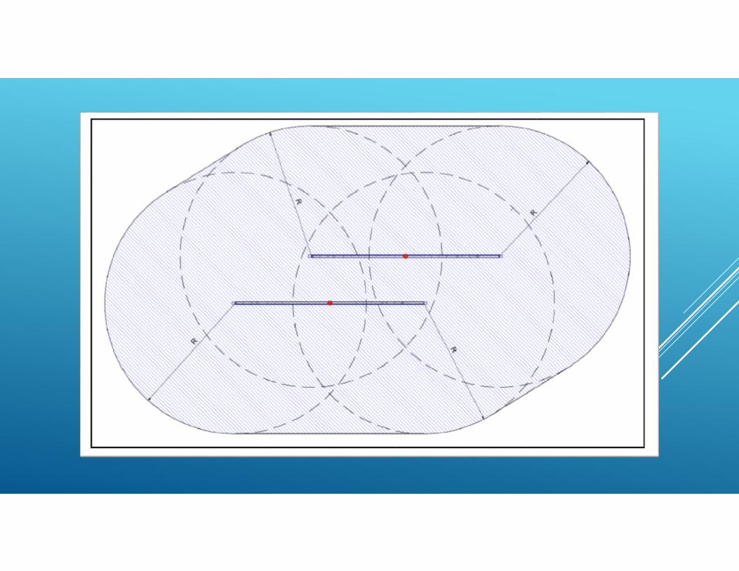
INNER HORIZONTAL SURFACE The inner horizontal surface is a horizontal surface above the aerodrome. The radius or outer limits of the inner horizontal surface shall be measured from a reference point or points established for such purpose. In this case, the Egyptian Authorities have selected the thresholds of the runways. For a Code number 4 RWY, independently of the approach category (even for non-instrumental ones), the radius will be 4000 m. The height of the inner horizontal surface shall be measured above (45 m) an elevation datum established for such purpose. In other way, the shape of the Inner Horizontal surface need not necessarily be circular. Guidance on determining the extent of the inner horizontal surface is contained in the Airport Services Manual, Part 6. With increasing aircraft speed may be necessary to adopt a no circular configuration (like a “racetrack”) and use circular arcs centered at the threshold on each runways connected by tangent lines.
CONICAL SURFACE
The conical surface is a surface sloping upwards and outwards from the periphery of the inner horizontal surface. Therefore, there will be defined a conical surface to every inner horizontal surface (lower and upper). The limits of the conical surface shall comprise: a) a lower edge coincident with the periphery of the inner horizontal surface; and b) an upper edge located at a specified height (100 m for code number “4” in every approach category) above the inner horizontal surface. The slope of the conical surface will be 5% and shall be measured in a vertical plane perpendicular to the periphery of the inner horizontal surface.

OUTER HORIZONTAL SURFACE Beyond the Aerodrome Obstacle Limitation Surfaces, construction of
high-rise buildings can be a problem for the safety or design of flight
procedures. This is why the Outer Horizontal Surface is defined.
Definition of this surface can be linked to inner horizontal and conical
surfaces.
In fact, this surface can be defined with the same rules applied to I.H.S.
replacing the 4000 m of distance/radius by 15000 m and the height of
45 m by 145 m, the same height of conical surface.

Inner Horizontal Surface
Conical Horizontal Surface
Outer Horizontal Surface
Outer Horizontal Surface
Outer Horizontal Surface
Outer Horizontal Surface
Conical Horizontal Surface
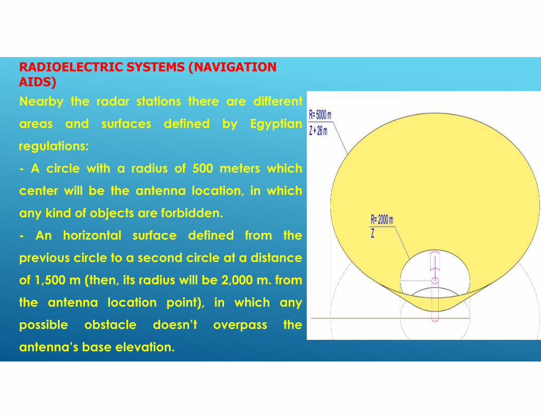
RADIOELECTRIC SYSTEMS (NAVIGATION AIDS) Nearby the radar stations there are different
areas and surfaces defined by Egyptian
regulations:
- A circle with a radius of 500 meters which
center will be the antenna location, in which
any kind of objects are forbidden.
- An horizontal surface defined from the
previous circle to a second circle at a distance
of 1,500 m (then, its radius will be 2,000 m. from
the antenna location point), in which any
possible obstacle doesn’t overpass the
antenna’s base elevation.

- From the previous circle to a circle located at
a distance of 3,000 m. (which radius will be
therefore 5,000 m.), will be a new surface with
an upslope of 0.87%. The elevation over the
antennas’’ base one will be 261 m.
- Additionally, within a radius of 930 meter from
the antenna, at least, will be forbidden to set up
any metallic edification or facility.
- It’s also forbidden to set up any power plant
inside the 5,000 m. circle around the antenna.
- At airports, with more than one radar, and in
which there is overlapping between the circles
of five kilometers of each radar, the height
permitted is the lowest one.


ILS: LOCALIZER The area limited by a strip that start 100 m behind
the antenna, extending until the RWY Threshold of
the procedure, and with a width of 300 m, 150 m
both sides of the centerline of RWY and LLZ
alignment, is restricted for setting up of trenches
and roads.
Within the area delimited by an 1%-up sloping
surface, only frangible objects would be admitted.
The limits of this surface shall comprise:
a) two sides originating at the antenna location
and diverging uniformly at an angle of 45º from the
extended center line of the runway; and
b) an outer edge perpendicular to the centerline of
the RWY, located at 15 km of the RWY end. Egyptian Reg. ILS-LOC surface characteristics

ILS/LOC 04L

ILS/LOC 22R

ILS/LOC 04C

ILS: GLIDE PATH In this case, there are not defined a sloped surface, only a restricted
area nearby the antenna, defined as a strip of 300 m (total width, 15 m
each side of the antenna), starting at the antenna location and aligned
with the runway until the approach line. A representation of the surface
would be the following:
Egyptian Reg. GP restricted area
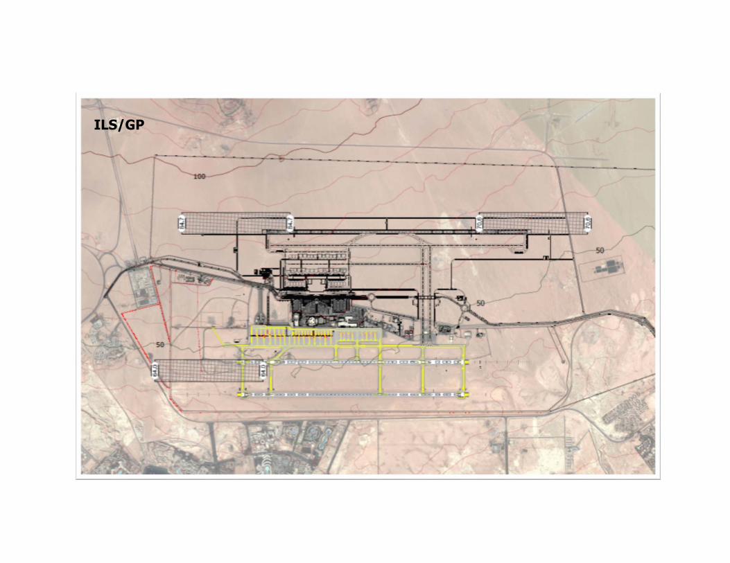
ILS/GP
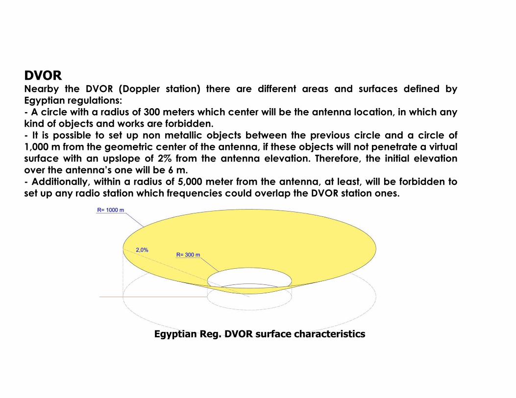
DVOR Nearby the DVOR (Doppler station) there are different areas and surfaces defined by Egyptian regulations: - A circle with a radius of 300 meters which center will be the antenna location, in which any kind of objects and works are forbidden. - It is possible to set up non metallic objects between the previous circle and a circle of 1,000 m from the geometric center of the antenna, if these objects will not penetrate a virtual surface with an upslope of 2% from the antenna elevation. Therefore, the initial elevation over the antenna’s one will be 6 m. - Additionally, within a radius of 5,000 meter from the antenna, at least, will be forbidden to set up any radio station which frequencies could overlap the DVOR station ones.
Egyptian Reg. DVOR surface characteristics

VOR

CONTROL TOWER: VHF/UHF ANTENNAS Nearby the Control Tower and associated to the UHF/VHT antennas, there are different areas and surfaces defined by Egyptian regulations: - A circle with a radius of 100 meters which center will be the antenna location, in which any kind of objects and works are forbidden. - It is possible to set up objects between the previous circle and a circle of 2,000 m from the geometric center of the antenna, if these objects will not penetrate a virtual surface with an upslope of 1% from the antenna elevation – 10 m (as an additional safety factor).
Egyptian Reg. VHF/UHF antennas surface

NEW CONTROL TOWER

RADIOELECTRIC OBSTACLE LIMITATION SURFACES

GENERAL RISK ANALYSIS
EGYPTIAN CIVIL AVIATION REGULATION DESIGNING CONFIGURATION

. Once the preliminary information and the initial studies have been developed and, once the Obstacle Limitation Surface Layout has been developed for the required scenarios (Egyptian Rules vs ICAO Standards and Existing vs Designing Configurations), it’s time to develop the General Risk Analysis as a prelude to develop the particular Aeronautical Studies, that are referred in the technical offer. Thus, the General Risk Analysis is trying to be a general tool to know the effect of the Obstacle Limitation Surface in the airport surroundings, in respect to the urban development. The scope of the General Risk Analysis is to set out some technical parameters to clarify which areas are suitable to develop new obstacles and which areas not, which are the maximum elevations and under what conditions. It will be possible to develop a preliminary assessment of the general risks, analyzing what areas are suitable to locate urban developments without any affection to the OLS. Also it will be possible to determine (in a first approach), if a simulation tool is applicable for navigation aids. It will be possible to set up an analysis if the existing terrain penetrates the obstacles limitation surfaces and where it would be possible to accept new building over the natural ground and its features

A General Risk Analysis can only be performed with the comparison of the existing topographic data. To compare the elevation data of the Limitation Surfaces with the elevation data on ground, it’s necessary to have topography survey with the adequate precision and parameters: - Geodetic Projection System (WGS84-UTM, ETM,) - Representation System - Compatible data with airport certified levels - Selection of height reference (Ellipsoid or orthometrtic) - Scale and Precision for base model - Scale and Precision for detailed survey (aeronautical studies) - Cartographic survey contents: Points and contour levels, land use, urban developments, communications roads, natural resources, labeling, etc. - Cartography survey range to include all the OLS (Approach surfaces, Outer Horizontal Surface, Circling area, etc.).

OPERATIONAL CHARACTERISTICS
For the referred runways, the ICAO code/letter identification is: 04L-22R: 4E 04C-22C: 4E 04R-22L: 4E
In respect to the Operational Category, according to the runways configuration, AIP information and procedure declarations:
RWY 04L: Instrumental Precision Approach Cat I RWY 04C: Instrumental Precision Approach Cat I RWY 04R: Instrumental Non Precision Approach RWY 22R: Instrumental Precision Approach Cat I (Only for this Study) RWY 22C: Instrumental Non Precision Approach RWY 22L: Instrumental Non Precision Approach
RADIOELECTRICAL CHARACTERISTICS
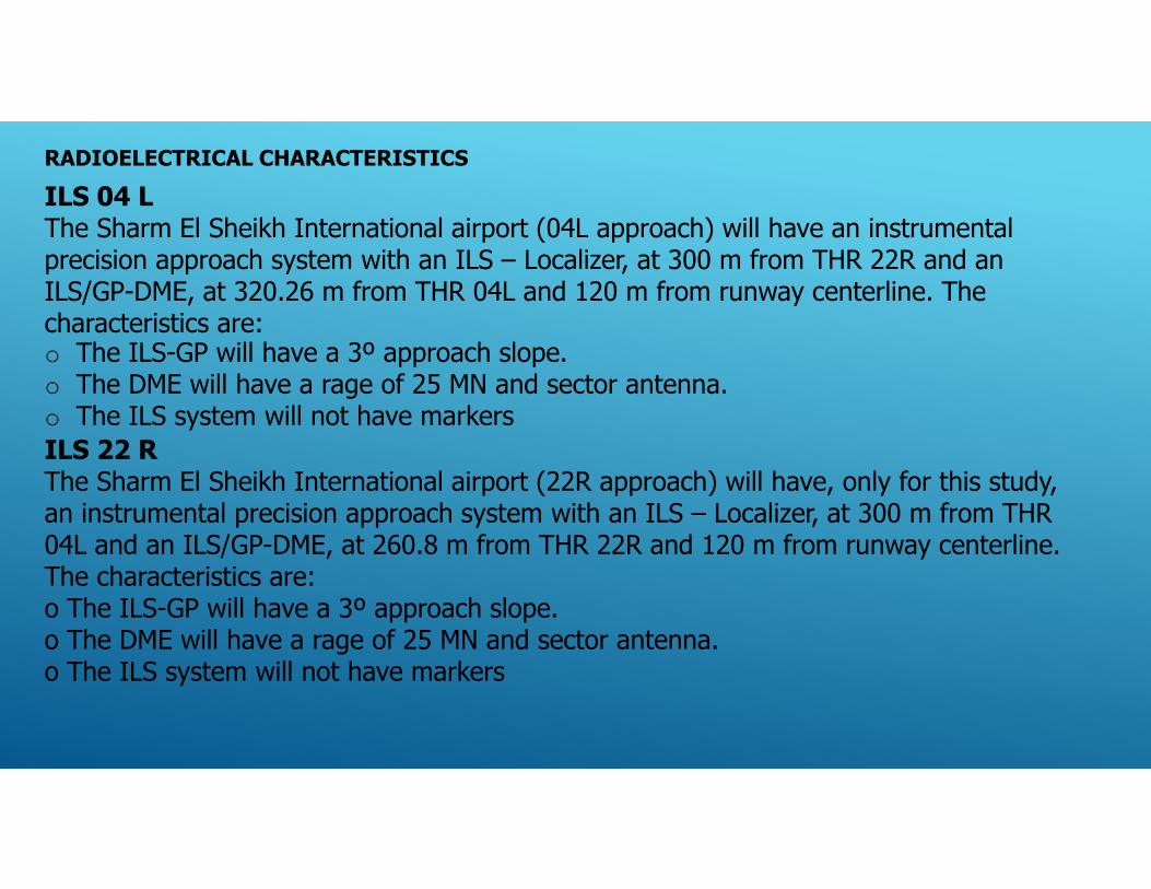
ILS 04 L The Sharm El Sheikh International airport (04L approach) will have an instrumental precision approach system with an ILS – Localizer, at 300 m from THR 22R and an ILS/GP-DME, at 320.26 m from THR 04L and 120 m from runway centerline. The characteristics are: o The ILS-GP will have a 3º approach slope. o The DME will have a rage of 25 MN and sector antenna. o The ILS system will not have markers ILS 22 R The Sharm El Sheikh International airport (22R approach) will have, only for this study, an instrumental precision approach system with an ILS – Localizer, at 300 m from THR 04L and an ILS/GP-DME, at 260.8 m from THR 22R and 120 m from runway centerline. The characteristics are: o The ILS-GP will have a 3º approach slope. o The DME will have a rage of 25 MN and sector antenna. o The ILS system will not have markers

ILS 04 C The Sharm El Sheikh International airport (04C approach) has an instrumental precision approach system (Cat II) with an ILS –Localizer, at 220 m from THR 22C and an ILS/GP-DME, at 300 m from THR 04C. The characteristics are: o The ILS/LOC antenna has 12 elements. o The ILS-GP has a 3º approach slope. o The DME has a rage of 25 MN and sector antenna. o The ILS system doesn’t have markers DVOR/DME This navigation aid is located inside the airport perimeter, at 1,000 m from THR 22C in centerline extension. The range of DVOR-DME is 200 NM. RADAR MSSR The Sharm El Sheikh International airport has an approach Radar located at the South of the airport. COMMUNICATIONS (A/A TRANSMISION AND RECEPCION) The A/A Communications facilities in Sharm El Sheikh Airport are supported at the New Control Tower

GENERAL RISK ANALYSIS. OVERALL VIEW :
The General Risk has been structured in three stages, to clarify its scope and to show the results in a more accurate way. The scheme of the analysis is:
Stage A – Development of available free heights around the OLS affected area
Stage B – Characterization of Aeronautical Studies around the OLS affected area
Stage C – Constructive Proposal for fixed obstacles

DEVELOPMENT OF AVAILABLE FREE HEIGHTS AROUND THE OLS AFFECTED AREA The drawing, shows the available distance between the existing terrain and the Obstacle Limitation Surfaces (the critical one) in any point. In other words, it shows the maximum allowed height, in any point, to locate a new obstacle. Importantly, the contour lines of this drawing don’t show the existing terrain elevation but the available free height between the terrain elevation and the elevation of the Critical Obstacle Limitation Surfaces, in any point of the affected area. The main contour lines have been represented each 10 m (dark green), and the minor contour lines each 5 m (light green). Also the drawing shows the area where the existing terrain penetrates the OLS. In this area, (purple dots), any construction is not allowed except with an approved Aeronautical Study or by applying shielding criteria. As summary, this drawing shows, in any point where the contour lines are present, the maximum height allowed of a new obstacle without penetration of the OLS. For more obstacle heights or other areas without contour lines, an Aeronautical Study has to be developed.
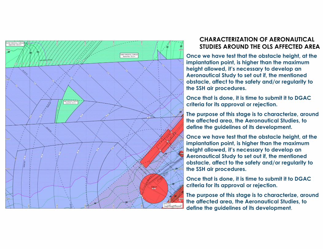
CHARACTERIZATION OF AERONAUTICAL STUDIES AROUND THE OLS AFFECTED AREA
Once we have test that the obstacle height, at the implantation point, is higher than the maximum height allowed, it’s necessary to develop an Aeronautical Study to set out if, the mentioned obstacle, affect to the safety and/or regularity to the SSH air procedures.
Once that is done, it is time to submit it to DGAC criteria for its approval or rejection.
The purpose of this stage is to characterize, around the affected area, the Aeronautical Studies, to define the guidelines of its development.

Red Area:
It's not allowed for locating any obstacle above the referred OLS (obstacle height ≥ free height contour line value). In case of Critical Areas (RWY strips and navigation critical areas) it’s not allowed to locate any fixed obstacle (except frangible one according to ICAO recommendations).
Solid Green Area:
It's possible to locate a fixed obstacle above the critical OLS; however an approved Aeronautical Study (by Civil Aviation Ministry) is needed. In this case, the critical surface is an Aerodrome OLS. To evaluate this Aeronautical Study, arguments based on air procedures have to be applied.
However, it should be emphasized that an Aeronautical Study has to take into consideration all the surfaces (not only the critical) that are penetrated by new obstacles. Therefore and related with the obstacle height, it could be necessary to evaluate the penetration not only aerodrome OLS, but radio electric OLS.
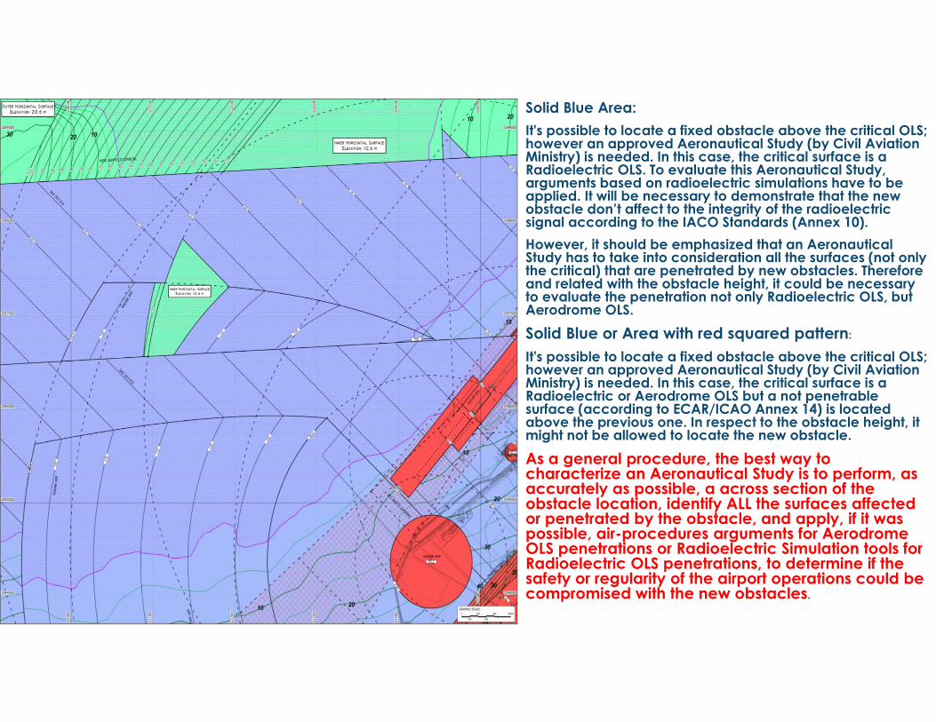
Solid Blue Area: It's possible to locate a fixed obstacle above the critical OLS; however an approved Aeronautical Study (by Civil Aviation Ministry) is needed. In this case, the critical surface is a Radioelectric OLS. To evaluate this Aeronautical Study, arguments based on radioelectric simulations have to be applied. It will be necessary to demonstrate that the new obstacle don’t affect to the integrity of the radioelectricsignal according to the IACO Standards (Annex 10). However, it should be emphasized that an Aeronautical Study has to take into consideration all the surfaces (not only the critical) that are penetrated by new obstacles. Therefore and related with the obstacle height, it could be necessary to evaluate the penetration not only Radioelectric OLS, but Aerodrome OLS. Solid Blue or Area with red squared pattern:
It's possible to locate a fixed obstacle above the critical OLS; however an approved Aeronautical Study (by Civil Aviation Ministry) is needed. In this case, the critical surface is a Radioelectric or Aerodrome OLS but a not penetrable surface (according to ECAR/ICAO Annex 14) is located above the previous one. In respect to the obstacle height, it might not be allowed to locate the new obstacle. As a general procedure, the best way to characterize an Aeronautical Study is to perform, as accurately as possible, a across section of the obstacle location, identify ALL the surfaces affected or penetrated by the obstacle, and apply, if it was possible, air-procedures arguments for Aerodrome OLS penetrations or Radioelectric Simulation tools for Radioelectric OLS penetrations, to determine if the safety or regularity of the airport operations could be compromised with the new obstacles.

CONSTRUCTIVE PROPOSAL FOR FIXED OBSTACLES As can be seen from above, a risk analysis cannot go deeper without knowing the height of the obstacle to be studied, since that depends that on one or more surfaces may be affected.
Thus, the last stage consists of propose obstacle of different heights and to obtain a new color map to reflect the areas where it’s possible to locate the building or where it’s necessary to develop an aeronautical study or lastly, where it’s not allowed to construct the referred obstacle.
The selected heights for the study were 10 m; 15 m; 20 m; 25 m; 30 m; 40 m and 50 m.
In this case, besides the obstacle limitation surfaces, the drawing includes the contour lines of the existing terrain to show a quick testing between the color areas and the composition with the terrain elevation, the obstacle height and the OLS critical elevation at the point of location.
These drawings have to be considered as a graphic approach to have an idea about the areas where it’s possible to locate an obstacle with a fixed height. These drawings will facilitate the task to select the area and to have a first idea about the relation between urban development and OLS requirements. Once, this first approach is obtained, a more accurate testing (i.e.: with numerical methods) has to be applied to obtain the final result.
Constructive proposal for an obstacle 30 m high.
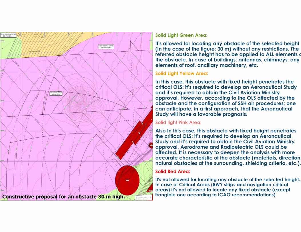
Solid Light Green Area:
It's allowed for locating any obstacle of the selected height (In the case of the figure: 30 m) without any restrictions. The referred obstacle height has to be applied to ALL elements othe obstacle. In case of buildings: antennas, chimneys, any elements of roof, ancillary machinery, etc. Solid Light Yellow Area:
In this case, this obstacle with fixed height penetrates the critical OLS: it’s required to develop an Aeronautical Study and it’s required to obtain the Civil Aviation Ministry approval. However, according to the OLS affected by the obstacle and the configuration of SSH air procedures; one can anticipate, in a first approach, that the Aeronautical Study will have a favorable prognosis. Solid light Pink Area:
Also In this case, this obstacle with fixed height penetrates the critical OLS: it’s required to develop an Aeronautical Study and it’s required to obtain the Civil Aviation Ministry approval. Aerodrome and Radioelectric OLS could be affected. It is necessary to deepen the analysis with more accurate characteristic of the obstacle (materials, direction,natural obstacles at the surrounding, shielding criteria, etc.). Solid Red Area: It's not allowed for locating any obstacle of the selected height. In case of Critical Areas (RWY strips and navigation critical areas) it’s not allowed to locate any fixed obstacle (except frangible one according to ICAO recommendations). Constructive proposal for an obstacle 30 m high.
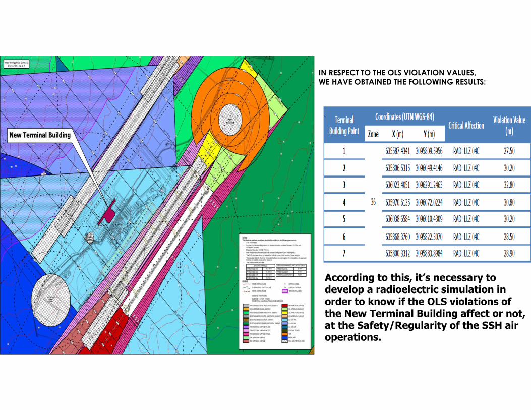
IN RESPECT TO THE OLS VIOLATION VALUES,WE HAVE OBTAINED THE FOLLOWING RESULTS:
`
According to this, it’s necessary to develop a radioelectric simulation in order to know if the OLS violations of the New Terminal Building affect or not, at the Safety/Regularity of the SSH air operations.

