cadd protocols for contractual deliverables · 2019. 7. 24. · practical completion 1 copy of...
TRANSCRIPT
CADD Protocols for Contractual
Deliverables
Guidelines
October 2011
PURPOSE:
Provides consultants and agencies with a clear understanding of CADD standards and BMW’s record-keeping requirements.
Content:
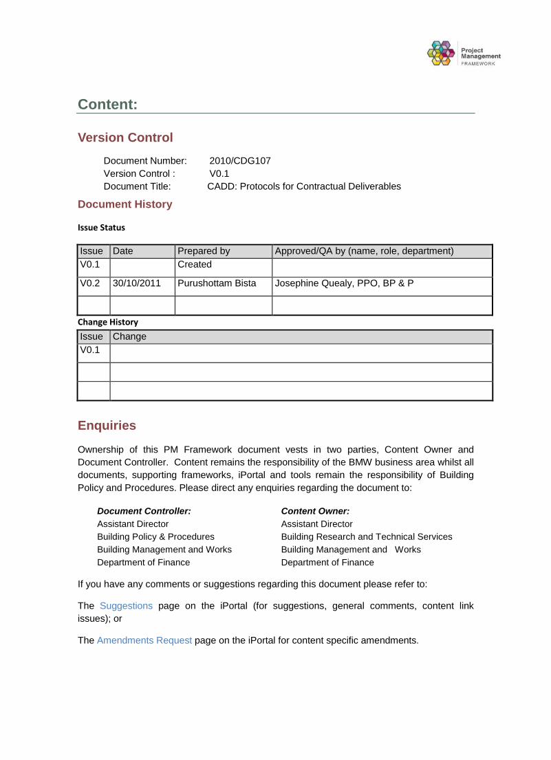
Version Control Document Number: 2010/CDG107 Version Control : V0.1 Document Title: CADD: Protocols for Contractual Deliverables
Document History
Issue Status
Issue Date Prepared by Approved/QA by (name, role, department) V0.1 Created
V0.2 30/10/2011 Purushottam Bista Josephine Quealy, PPO, BP & P
Change History
Issue Change V0.1
Enquiries
Ownership of this PM Framework document vests in two parties, Content Owner and Document Controller. Content remains the responsibility of the BMW business area whilst all documents, supporting frameworks, iPortal and tools remain the responsibility of Building Policy and Procedures. Please direct any enquiries regarding the document to:
Document Controller: Assistant Director Building Policy & Procedures Building Management and Works Department of Finance
Content Owner: Assistant Director Building Research and Technical Services Building Management and Works Department of Finance
If you have any comments or suggestions regarding this document please refer to:
The Suggestions page on the iPortal (for suggestions, general comments, content link issues); or
The Amendments Request page on the iPortal for content specific amendments.

Contents
Introduction 5
Relevance of Standards 5
Why Do Cadd Protocols Exist? 5 Legislative Reasons 5 Retrieval 5
Schedule of Documentation to be Supplied 6 Contract Documentation 6 Practical Completion 6
Provision of Data to the Department of Housing and Works 6
Consultant Templates 7
Existing Drawings 7
PDF Standards 9
General 9
PDF File Naming 9
PDF Delivery Requirements 9
Provision of Data to the Department of Housing and Works 10
Viewing PDF Files 10
Drafting Standards 11
Drawing File Naming 11
Characters 1 to 3 11 Character 4 11 Characters 5 & 6 11 Character 7 12 Character 8 12 Typical Example 12
Australian Standards 13
Graphic Symbols 13
Linework 13
Lettering 14
Scale 14
Shading 14
Title Block 14
Cover Sheet Title Block 14
External Referencing 14
Model Space / Paper Space 15
Purging 15
Limits 15
Layers 15
Entities Outside Drawing Borders 15
Orientation 15
Symbolic Representation of Materials 15
Amendments 15
Asset Management Drawing Standards 17
Site Plans 17
Floor Plans 18
CADD Layering Protocol 19
General 19
Architectural / Structural Layers 20
Hydraulics 21
Mechanical 21
Electrical 21
Interior Fitout 22
Project and Drawing Information Sheets 23
CADD Drawing Checklist 23
Project and Drawing Information Sheets 23
Appendix A - Title Block 25
Appendix B - Cover Sheet Title Block 27
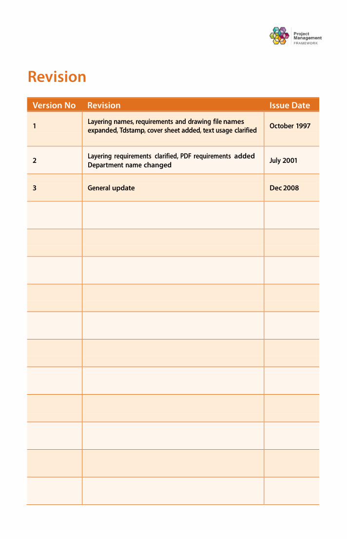
Revision
Version No Revision Issue Date
1
Layering names, requirements and drawing file names expanded, Tdstamp, cover sheet added, text usage clarified
October 1997
2
Layering requirements clarified, PDF requirements added Department name changed
July 2001
3
General update
Dec 2008


5
Introduction This document outlines the Department of Housing and Works’ requirements for ‘Tender‘ and ‘As Constructed’ drawings and sets out conditions for the delivery of contract documentation
This Manual aims to:
* Provide Consultants with a clear understanding of the reason for the Standards;
* To align the Department of Housing and Works CADD Standards for Deliverables as best as possible with existing industry standards with consideration to the Department of Housing and Works’ requirements as outlined in the State Records Act 2000; and
* Ensure all associated parties are clear about the legislation that governs the need to retain CADD records
Techniques and methods used by consultants throughout the design documentation phase can vary from the requirements outlined in this Manual, however drawings related to Tender, Practical Completion as well as changes made during the defects period must conform to the following prescribed protocols
The Manual reflects current industry standards with consideration to the Department of Housing and Works’ legislative obligations as detailed in the State Records Act 2000
For further information please contact the the Department of Housing and Works CADD Manager on 9440 2241 Electronic documents and associated templates can be located at www.dhw.wa.gov.au/CADD
Why Do CADD Protocols Exist?
The Department of Housing and Works CADD Protocols forms a part of the Department of Housing and Works’ Contractual Deliverables for a number of reasons This section serves to inform all relevant parties as to the rationale for its inclusion in Contract documents, as well as why they are regarded as a deliverable of high importance

6
Legislative reasons The State Records Act 2000, in conjunction with the Department of Housing and Works’ Record Keeping Policy specifies CADD drawings as State Archives Section 3 of the State Records Act 2000 defines a State Archive as “a State Record that is to be retained permanently”
The State Records Commission Standards outline minimum requirements for Government record keeping Standard 6 – ‘Outsourcing’ asserts “State Organisations ensure that contractors comply with the record keeping controls determined by the record keeping plan of the organization” (SRC Standard 6 Outsourcing, Principle 3, State Records Commission of Western Australia, February 2002, p 7) Furthermore, the Standard stipulates that Government organisations must ensure that State Records are returned upon contract completion Further information on the State Records Act 2000 and the State Records Commission Standards can be located at http://www.sro.wa.gov.au/src/
The CADD Standards serve to meet the Department of Housing and Works’ legislative obligation to retain State Archive Records as per the above described requirements
Retrieval State Government drawings are utilized for a variety of purposes This varies from upkeep and maintenance reasons, through to replication for similar projects For example, many schools are built based on existing designs owned by the Government Copies of existing drawings are provided to the consultant as a template for designing the new project This Manual ensures that all drawings are supplied in a simple consistent format that is easy to retrieve for the life of the building
For this and many more reasons, the Department of Housing and Works is required to ensure that all drawings are stored in their recoverable and editable native format
Schedule of Documentation to be Supplied
The Consultant shall supply the following documents to the Principal’s Representative
Contract Documentation 1 copy of computer CADD documentation of, “Tender Documents” in PDF format “ and
1 copy of computer CADD documentation of “Tender Documents” in DWG format
Practical Completion 1 copy of computer CADD documentation of
“As Constructed” drawings in DWG format
1 copy of computer CADD documentation of ”As Constructed” Asset Management drawings in DWG format
CADD drawings must be provided in the above electronic formats on CD-Rom or DVD
NOTE: At Practical Completion, ALL tender drawings are to be updated to reflect “AS CONSTRUCTED” and are to be clearly labelled as such
7
Provision of Data to the Department of Housing and Works
Currently the Department of Housing and Works operates AutoCAD 2007 Commissioned Consultants are to ensure that their CADD system can produce electronic copies of the drawings in a format compatible to a minimum of AutoCAD 2004
Where another CADD system is used, it shall be the responsibility of the Consultant, to supply drawings to the Department of Housing and Works to a minimum format of AutoCAD 2004 .DWG only.
No raster images shall be included in the data delivered to the Department of Housing and Works
Consultants shall complete the deliverables checklist on OCM, to signify that they have complied with the Department of Housing and Works requirements
No manual updating of CADD drawings is allowed
The supply of “As Constructed” CADD drawings (including those from sub-consultants) to the Department of Housing and Works remains the responsibility of the lead consultant.
Consultant Templates
The following file types shall be used by the consultants All files are available on line at www.dhw.wa.gov.au
File Description
A1base DWG
A1 size (841 x 594) base drawing with title block with standard text
All drawings shall be produced using only A1 size sheets utilising the standard A1 size the Department of Housing and Works base drawing sheet incorporating the border, logo and title block layout
A1base DXF
A1 base drawing template for use with other CADD systems
The A1base DXF should be converted into a drawing relevant to your CADD system
Make sure that the limits of the drawing sheet are set to the extents of the A1base drawing as inserted at the plot scale Also ensure that 0,0 is set to the bottom left hand corner of the drawing sheet
Cover DWG
A1 size cover drawing with title block with standard text
This is to be used by all consultants and sub-consultants in their documentation
Logos are to be inserted in the area provided at the base of the cover sheet title block
A NOTE: NO logos are to appear above the State Government Crest.
6
Cover DXF Cover drawing template for use with other CADD systems
The Cover DXF should be converted into a drawing relevant to your CADD system
Make sure that the limits of the drawing sheet are set to the extents of the Cover drawing as inserted at the plot scale Also ensure that 0,0 is set to the bottom left hand corner of the drawing sheet
For use of different sheet sizes please contact Gary Marcon, CADD Manager for approval
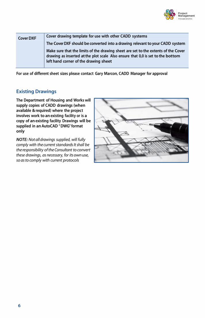
Existing Drawings
The Department of Housing and Works will supply copies of CADD drawings (when available & required) where the project involves work to an existing facility or is a copy of an existing facility Drawings will be supplied in an AutoCAD “ DWG” format only
NOTE: Not all drawings supplied, will fully comply with the current standards It shall be the responsibility of the Consultant to convert these drawings, as necessary, for its own use, so as to comply with current protocols

9
PDF Standards for Tender
General
This format file is applicable to tender documents only Files are to be delivered to the the Department of Housing and Works Tender’s Office The ability to produce PDF files (portable document format) is available via the “Plot” function in all current versions of AutoCAD
PDF File Naming
The following file naming format ensures consistency and ease of recognition of drawings by contractors and sub contractors. Files must be renamed according to the following standard before saving
Examples of Architectural drawing file name format are - A1siteplan, A2adminfloorplan, A3adminelevations, A4adminsections, A5admindetails etc
Examples of sub-consultant drawings file name format are - S1adminconcplan, S2adminconcdets, M1siteplan, M2adminblock, E1siteplan, E2adminblockpower, etc
NOTE: NO reserved characters are to be used in the file name (eg: &, /, \ ) as this can cause file viewing problems.
PDF Delivery Requirements
Limits are to be set and the bottom left corner of the sheet is to be at 0,0
Final tender drawings are to be ‘zoomed’ to limits, before passing to the Department of Housing and Works Tenders Office This ensures that all files will appear the same size when viewed
Only one drawing is to be contained per PDF file (The number of PDF files supplied must be equal to the number of hard copy drawings in the tender set )
All entities outside the drawing boundaries are to be erased
The Grid toggle is to be turned off
Non standard fonts are not to be used
All PDFs to appear in black and white only
All files created must be viewed by the consultant to ensure that they open correctly, prior to delivery to the Department of Housing and Works.

10 Contrac t for Ser vice – CADD Documentation Procedures Manual
Delivery of PDF Standards to the Department of Housing and Works
Supply ALL files to the Department of Housing and Works in a compressed ZIP file format using pkzip/WinZip
GEM requires files be no larger than 4 0mb in size
Zip files can be delivered to the Department of Housing and Works on CD-Rom/DVD or via email to the Tenders Office ([email protected])
Zip file names shall be in the format of project title + discipline For example:
Bakers Hill PS architectural drawings zip;
Bakers Hill PS mechanical drawings zip, etc
If more than one zip file is required for a discipline then they shall be numbered as such For example:
Bakers Hill PS architectural drawings1 zip
Bakers Hill PS architectural drawings2 zip,
If the project has only a limited number of drawings and they are of small size, then they can be compressed into a single zip file For example:
Bakers Hill PS drawings zip
The delivery of PDF files, is in addition to the requirement for all consultants to supply AutoCAD DWG’s (tender DWG’s and ‘As Constructed’ DWG’s) as stated in the RFP shell and Specifications detailed under “Provision of Data to the Department of Housing and Works”
All AutoCAD PDF files supplied to the Department of Housing and Works will be identical in content to the corresponding hard copy drawing supplied
11 Contrac t for Ser vice – CADD Documentation Procedures Manual
Drafting Standards
Drawing File Naming
All drawing files must consist of 8 characters as detailed below
Characters 1 to 3 Identifies the job description in a minimum of 3 characters
For example - JPC = Joondalup Police Complex
Character 4 Identifies the Practice or Discipline and must use the following characters as applicable
A = Architectural C = Civil E = Electrical M = Mechanical S = Structural I = Irrigation D = Interior Fit out F = Fire and/or Security L = Landscaping N = Marine P = Plumbing (Hydraulic) T = Telecommunications U = Survey X = Xref Drawing (refer NOTE)
NOTE: It is acceptable to use unmodified drawings for external referencing However where the drawing is modified in any way prior to its use as an external reference the drawing must be named with the X prefix to distinguish it from the original drawing
Characters 5 & 6 Identify the drawing number
For example - 01 through to 99
12 Contrac t for Ser vice – CADD Documentation Procedures Manual
Character 7 Identifies the drawing description and must use the following characters as applicable
A = Site Plan and or Details P = Plan C = Ceiling Plans R = Roof Plans E = Elevations S = Sections D = Details L = Room Layouts W = Window Schedules O = Door Schedules F = Furniture Details M = Miscellaneous
Character 8 Identifies the drawing scale via the following characters
0 = 1:1 1 = 1:5 2 = 1:10 3 = 1:20 4 = 1:50 5 = 1:100 6 = 1:200 7 = 1:500 8 = 1:1000 9 = 1:2000
Refer to Section 3 6 for information on determining plot scale
Typical Example JPCA01P5 or JPCA01A7
The Principal Consultant is to ensure that all sub consultants have the same 3 characters at the start of each file name
A file naming convention that allows for more than 100 drawing numbers or that allows the drawings number to reflect individual buildings is available Approval must be sought from the Department of Housing and Works CADD Manager before use
13 Contrac t for Ser vice – CADD Documentation Procedures Manual
Australian Standards
Drawings shall meet the requirements of the Australian Standard drafting codes detailed below
AS 1100 101-1992 Technical Drawing General Principles
AS 1100 201-1992 Technical Drawing Mechanical Drawing
AS 1100 301-1985 Technical Drawing Architectural Drawing
AS 1100 401-1984 Technical Drawing Engineering Survey, Engineer Survey/Design Drawings
AS/NZS 1100 501-2002 Technical Drawing Structural Engineering Drawings
AS 3883-1991 Computer Graphics Computer Aided Design (CAD) – Guide for Structuring of Computer Graphic Information
Graphic Symbols
Refer to the relevant Australian Standards Association publications
Linework
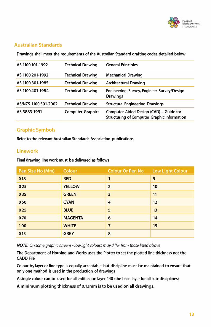
Final drawing line work must be delivered as follows
Pen Size No (Mm) Colour Colour Or Pen No Low Light Colour
0 18 RED 1 9
0 25 YELLOW 2 10
0 35 GREEN 3 11
0 50 CYAN 4 12
0 25 BLUE 5 13
0 70 MAGENTA 6 14
1 00 WHITE 7 15
0 13 GREY 8
NOTE: On some graphic screens - low light colours may differ from those listed above
The Department of Housing and Works uses the Plotter to set the plotted line thickness not the CADD File
Colour by layer or line type is equally acceptable but discipline must be maintained to ensure that only one method is used in the production of drawings
A single colour can be used for all entities on layer 440 (the base layer for all sub-disciplines)
A minimum plotting thickness of 0.13mm is to be used on all drawings.
14 Contrac t for Ser vice – CADD Documentation Procedures Manual
Lettering
Due to copyright laws, all lettering for standard drafting documentation shall be AutoCAD standard font file ISOCP2 vertical, plain, uncondensed, to minimum text height of 2mm with a 0 25mm thickness
All text shall be UPPERCASE only
Scale
ALL drawings shall be constructed at FULL SIZE Under no circumstances is a drawing to be scaled unless it is an INSERTED BLOCK
The drawing measurement is to be set to millimetres for building works and geographical drawings (survey drawings) The scale of the final drawing, (which determines the initial insertion of the BASE drawing) is to reflect the smallest scale drawing on the sheet For example, if the drawing is a 1:20 section with 1:5 details, the 1:20 section takes precedence for the plot scale
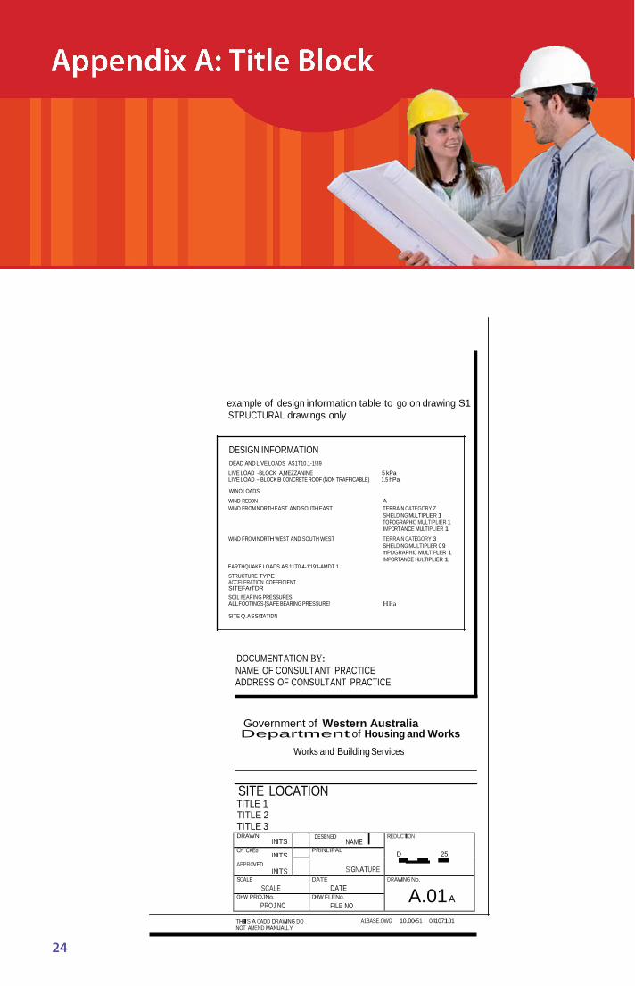
Title Block
Refer to Appendix A for example of the Title Block
Detailed titles for each drawing shall be determined in discussion with the Project Manager and shall be consistently applied throughout, regardless of discipline
Cover Sheet Title Block
Refer to Appendix B for example of Cover Sheet Title Block
Titles for cover sheets shall be consistent with drawing title block and shall be consistently applied throughout, regardless of discipline
External Referencing
The methodology of producing drawings using the Xref or XCLIP command of AutoCAD is acceptable
The “PATH” for the Xref file shall be set to default to the current working directory
The XREF drawing file(s) may be bound into the main drawing file, providing the total file size does not exceed 1 5Mb and the Xref drawing file(s) do NOT contain any frozen or turned off layers
The Consultant will supply all Xref drawing file(s) and will use the appropriate drawing naming conventions
All Xref’s shall contain only the layers required. All layers not required, shall be deleted.
The CADD Drawing Information sheet (available online at www.dhw.wa.gov.au /CADD) must be completed
All external reference files used in drawings shall be inserted on Layer 440 (base layer).
15 Contrac t for Ser vice – CADD Documentation Procedures Manual
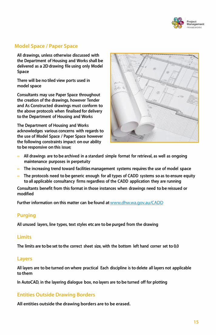
Model Space / Paper Space
All drawings, unless otherwise discussed with the Department of Housing and Works shall be delivered as a 2D drawing file using only Model Space
There will be no tiled view ports used in model space
Consultants may use Paper Space throughout the creation of the drawings, however Tender and As Constructed drawings must conform to the above protocols when finalised for delivery to the Department of Housing and Works
The Department of Housing and Works acknowledges various concerns with regards to the use of Model Space / Paper Space however the following constraints impact on our ability to be responsive on this issue;
n All drawings are to be archived in a standard simple format for retrieval, as well as ongoing
maintenance purposes in perpetuity n The increasing trend toward facilities management systems requires the use of model space n The protocols need to be generic enough for all types of CADD systems so as to ensure equity
to all applicable consultancy firms regardless of the CADD application they are running
Consultants benefit from this format in those instances when drawings need to be reissued or modified
Further information on this matter can be found at www.dhw.wa.gov.au/CADD
Purging
All unused layers, line types, text styles etc are to be purged from the drawing
Limits
The limits are to be set to the correct sheet size, with the bottom left hand corner set to 0,0
Layers
All layers are to be turned on where practical Each discipline is to delete all layers not applicable to them
In AutoCAD, in the layering dialogue box, no layers are to be turned off for plotting
Entities Outside Drawing Borders
All entities outside the drawing borders are to be erased.

16 Contrac t for Ser vice – CADD Documentation Procedures Manual
Orientation
Orientate all plans and parts of plans so that NORTH is towards the top of the sheet where possible
Symbolic Representation of Materials
Refer to AS 1100 - Part 301 – 1992
Amendments
Amendments to drawings shall be marked and NOTED in the amendment and title blocks
Letters shall be used for pre-tender amendments and numerals shall be used for post tender amendments
17 Contrac t for Ser vice – CADD Documentation Procedures Manual
This section applies only to practical completion documentation for completely new facilities It does not apply to additions or alterations to existing buildings
The Department of Housing and Works have recognised the need for Asset Management Plans to be a requirement of new construction following the increasing trend in Government, toward Facilities Management applications This section details what consultants must supply at Practical Completion of ‘new facilities’
The consultant shall supply the following on CD-Rom or DVD upon practical completion:
n An electronic copy of the site and floor plan/s in AutoCAD DWG format n A ‘black and white’ copy of each site and floor plan in Adobe PDF format
Layering, colours etc are to comply with the Department of Housing and Works CADD Documentation Procedures Manual
NOTE: The West Australian Country Health Service has detailed requirements for the Asset Management plans for its facilities This protocol is available at www dhw wa gov au/CADD Alternatively please contact your the Department of Housing and Works Project Manager
Site Plans
All site plans are to:
n Be drawn in model space n Have a Scale 1:1 (mm) n Be Geospatially located and oriented n Have Units set to millimetres (drawing must not be ‘unitless’) n Have each floor plan/s inserted in its correct spatial location and relationship to other blocks n Have no layers ‘frozen’ or turned ‘off’ n For printing purposes layout space can be used with an appropriate viewport scale (1:200,
1:500, 1:1000)
The following layers shall remain. All other layers are to be removed from the site plan.
n The Title block and drawing sheet n The North point
18 Contrac t for Ser vice – CADD Documentation Procedures Manual
Asset Management Drawing Standards n
Contour lines n The New Building outline n The Existing building outline n All roads or car parks n All car bays n All paths, ramps etc n All physical features (fences, trees, bollards, goal posts,
retaining walls, stairs, kerbs, external lights etc) n Any visible components of in ground services
(manholes, pits etc)
Site service mains from building boundary to entry point into new buildings are to be shown on the site plan
For printing purposes layout space can be used with an appropriate viewport scale (1:200, 1:500, 1:1000)
All other information is to be erased and the layers deleted and the drawing purged.
Floor Plans
All floor plans are to:
n Have 1 floor plan per drawing file n Be drawn In model space (Draw complete blocks (no breaks) n Be drawn at 1:1mm and then Geospatially located and oriented n Have Units set to millimetres (drawing must not be ‘unitless’) n Have no layers ‘frozen’ or turned ‘off’
For printing purposes layout space can be used with an appropriate viewport scale (1:50, 1:100)
The layers to remain are those containing:
n The Title block and drawing sheet n Walls n Windows n Doors n Room names n Floor finishes n Any fixed furniture n Columns (concrete or steel columns) n Any plumbing fixture (basins, toilets and urinals)

19 Contrac t for Ser vice – CADD Documentation Procedures Manual
All other information is to be erased, layers deleted and the drawing purged.
20 Contrac t for Ser vice – CADD Documentation Procedures Manual
CADD Layering Protocol
This standard is designed to ensure the Department of Housing and Works and its future Consultants can easily retrieve relevant information The usage of this layering system serves to ensure that other Consultants using original documents are easily able to identify entities from the existing drawings
The CAMS/Department of Housing and Works layering system was developed at a time when project documentation was done “in house” It is based on the 3 digit numbering system used by the “NATSPEC” specification package (NATSPEC Classification Manual ISBN 0 7316 6401 9) and was adopted and developed at a time when NATSPEC was being introduced as a nation wide specification system
The protocol uses numbers based on hundreds, tens and units The numbers shown in the table below are generally considered to be the PRIMARY numbers For example:
n 250 STRUCTURAL STEEL
Consultant(s) can place information associated with that primary number on another layer by creating a SECONDARY definition For example:
n 250 STEEL COLUMNS, 250 STEEL BEAMS, 250 STEEL PURLINS n 465 DOOR, 465 DOOR No
Survey drawings are also to use the protocol to present their information For example:
n 072 KERB, 072 KERB TXT, 072 KERB RL n 140 TREE, 140 TREE TXT, 140 TREE RL n 231 BUILDING, 231 BUILDING TXT, 231 BUILDING RL
Drawings produced by all Consultants must conform to the Department of Housing and Works layering system as follows:
n All DRAWINGS shall be drawn utilising the layering protocol described on the following pages n All LAYERS must have layer number as well as layer definition
for example 050-NEW LEVELS n Layer definition can be abbreviated as long as the naming remains clear
for example 250-S-BEAMS, 250-S-COLS
Colour by layer and line type is acceptable Questions regarding this layering system should be referred to the CADD Manager

20
Layer No Layer Definition
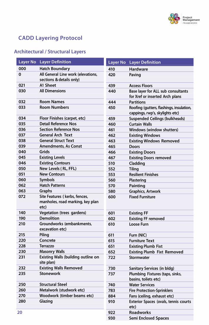
410 Hardware 420 Paving
439 Access Floors 440 Base layer for ALL sub consultants
for Xref or inserted Arch plans 444 Partitions 450 Roofing (gutters, flashings, insulation,
cappings, rwp’s, skylights etc) 459 Suspended Ceilings (bulkheads) 460 Curtain Walls 461 Windows (window shutters) 462 Existing Windows 463 Existing Windows Removed 465 Doors 466 Existing Doors 467 Existing Doors removed 510 Cladding 552 Tiling 553 Resilient Finishes 560 Plastering 570 Painting 580 Graphics, Artwork 600 Fixed Furniture
601 Existing FF 602 Existing FF removed 610 Loose Furn
611 Furn (NIC) 615 Furniture Text 651 Existing Plumb Fixt 652 Existing Plumb Fixt Removed 722 Stormwater
730 Sanitary Services (in bldg) 737 Plumbing Fixtures (taps, sinks,
basins, toilets etc) 740 Water Services 783 Fire Protection-Sprinklers 884 Fans (ceiling, exhaust etc) 910 Exterior Spaces (ovals, tennis courts
etc) 922 Roadworks 930 Semi Enclosed Spaces
CADD Layering Protocol
Architectural / Structural Layers
Layer No Layer Definition 000 Hatch Boundary 0 All General Line work (elevations,
sections & details only) 021 A1 Sheet 030 All Dimensions
032 Room Names 033 Room Numbers
034 Floor Finishes (carpet, etc) 035 Detail Reference Nos 036 Section Reference Nos 037 General Arch Text 038 General Struct Text 039 Amendments, As Const 040 Grids 045 Existing Levels 046 Existing Contours 050 New Levels ( RL, FFL) 051 New Contours 060 Symbols 062 Hatch Patterns 063 Graphs 072 Site Features ( kerbs, fences,
manholes, road marking, key plan etc)
140 Vegetation (trees gardens) 190 Demolition 210 Groundworks (embankments,
excavation etc) 215 Piling 220 Concrete 228 Terrazzo 230 Masonry Walls 231 Existing Walls (building outline on
site plan) 232 Existing Walls Removed 235 Stonework
250 Structural Steel 260 Metalwork (studwork etc) 270 Woodwork (timber beams etc) 280 Glazing

21 Contrac t for Ser vice – CADD Documentation Procedures Manual
Layer No Layer Definition
728 Special Services 730 Sanitary Services (in bldg) 734 Existing Services 737 Plumbing Fixtures (taps, sinks,
basins, toilets etc) 739 Vents 740 Water Services (tanks) 741 External Services – Mains (fire,
water) 742 Cold Water Supply 743 Hot Water Supply
Layer No Layer Definition 870 Heating Water (boilers, hot water units
etc) 879 Heating Appliances 880 Air Handling Ductwork 884 Fans (ceiling, exhaust) 887 Exhaust Systems 888 Dust Extraction System 889 Room a/c ( fan coil units etc)
Layer No Layer Definition
818 Wiring layout (power, lighting) 819 Wiring Protect & Support
(Conduits, Pits, Cable Trays on Plans) 821 Electrical Accessories 823 Switch and Control Gear 825 Electrical Appliances 828 Luminaires 838 Earthing Installations 839 Lightning Protection 845 Energy Conservation System 846 Security System 884 Fans (ceiling, exhaust) 892 Lifts (passenger) 893 Lifts (goods)
Hydraulics
Layer No Layer Definition
702 Existing Services Text 709 General Hydr Text 710 Hydraulic Accessories 720 Drainage
721 External Services - Sewer 722 Stormwater 724 Mechanical Drains
725 Toxic Wastes 727 Sewer Treatment
Mechanical
Layer No Layer Definition 745 Chilled Water (& chillers)
747 Irrigation 749 Condensed Water System 750 Gas, Steam, Air Pipework 755 Medical Gas 760 Waste Disposal 850 Mechanical Services (Notes, machinery,
etc) 860 Refrigeration Services
Electrical
Layer No Layer Definition
780 Fire Protection - General Zones 787 Fire and Smoke Detection
790 Communications - General Zones 791 Telecomm and Computers 793 Intercoms 794 Radio Systems 795 Public Address 797 Audio Visual 798 Recording 799 Warning and Evacuation 800 Electrical - General NOTEs 810 Switchboard Zones 811 Switchboard Symbols
22
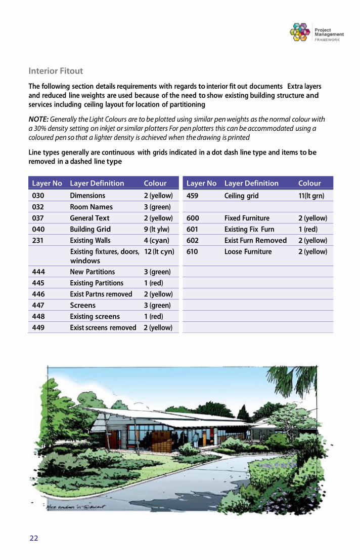
Layer No Layer Definition Colour
459 Ceiling grid 11(lt grn)
600 Fixed Furniture 2 (yellow) 601 Existing Fix Furn 1 (red) 602 Exist Furn Removed 2 (yellow) 610 Loose Furniture 2 (yellow)
Interior Fitout
The following section details requirements with regards to interior fit out documents Extra layers and reduced line weights are used because of the need to show existing building structure and services including ceiling layout for location of partitioning
NOTE: Generally the Light Colours are to be plotted using similar pen weights as the normal colour with a 30% density setting on inkjet or similar plotters For pen plotters this can be accommodated using a coloured pen so that a lighter density is achieved when the drawing is printed
Line types generally are continuous with grids indicated in a dot dash line type and items to be removed in a dashed line type
Layer No Layer Definition Colour
030 Dimensions 2 (yellow) 032 Room Names 3 (green) 037 General Text 2 (yellow) 040 Building Grid 9 (lt ylw) 231 Existing Walls 4 (cyan)
Existing fixtures, doors, 12 (lt cyn) windows
444 New Partitions 3 (green) 445 Existing Partitions 1 (red) 446 Exist Partns removed 2 (yellow) 447 Screens 3 (green) 448 Existing screens 1 (red) 449 Exist screens removed 2 (yellow)
23 Contrac t for Ser vice – CADD Documentation Procedures Manual
The CADD Drawing Checklist, CADD Project Data Information and CADD Drawing Information sheets are available for download on line at www dhw wa gov au/CADD Consultants shall supply completed copies to the Department of Housing and Works with CADD disks It is the Consultant’s responsibility to check regularly for updates to any CADD related data
The above information is required for ease of retrieval
CADD Drawing Checklist
Complete and sign the checklist to signify compliance with the Department of Housing and Works requirements
All drawings must be supplied on CD-Rom/DVD and in the prescribed format
All disks shall be scanned for virus infections prior to issue to the Department of Housing and Works.
Project and Drawing Information Sheets
Complete and return the Project Data Information Sheet to the Department of Housing and Works
NOTE: A separate CADD Drawing Information Sheet must be supplied for each disk complete with all information
24
DRAWN INITS NAME I REDUCTION
D 25 CH CKEo
INITS PRINLIPAL
SIGNATURE
APPROVED INITS
SCALE SCALE
DATE DATE
DRAWING No.
A.01A OHW PROJNo. PROJ NO
DHW FLENo. FILE NO
example of design information table to go on drawing S1 STRUCTURAL drawings only
DESIGN INFORMATION DEAD AND LIVE LOADS AS1T10.1-1!89 LIVE LOAD -BLOCK A,MEZZANINE 5 kPa LIVE LOAD - BLOCK B CONCRETE ROOF (NON TRAFFICABLE) 1.5 hPa
WINO LOADS
WIND REGOI N WIND FROM NORTH EAST AND SOUTHEAST
WIND FROM NORTH WEST AND SOUTH WEST
EARTHQUAKE LOADS AS 11T0.4-1'193-AMDT.1 STRUCTURE TYPE ACCELERATION COEFFICIENT SITEFArTDR SOIL I!EARING PRESSURES ALLFOOTINGS {SAFE BEARING PRESSURE!
SITE Q.ASSIC'IATIDN
A TERRAIN CATEGORY Z SHIELDING MULTIPLIER 1 TOPOGRAPHIC MULTIPLIER 1 IMPORTANCE MULTIPLIER 1
TERRAIN CATEGORY 3 SHIELDING MULTIPLIER 0.9 mPDGRAPHIC MULTIPLIER 1 IMPORTANCE HULTIPLIER 1
HPa
DOCUMENTATION BY: NAME OF CONSULTANT PRACTICE ADDRESS OF CONSULTANT PRACTICE
Government of Western Australia Department of Housing and Works
Works and Building Services
SITE LOCATION TITLE 1 TITLE 2 TITLE 3
- - -
DESGI NED
THSIIS A CADD DRAWING DO NOT AMEND MANUALLY
A1BASE.OWG 10.00•51 04107101
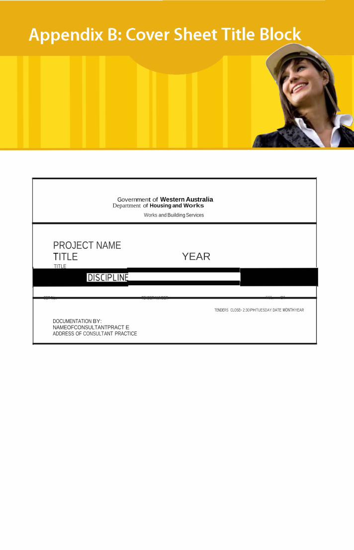
Government of Western Australia Department of Housing and Works
Works and Building Services
PROJECT NAME TITLE TITLE
YEAR
SET No. TENDER NUMBER VOL. Of
TENDERS CLOSE• 2:30 PH TUESDAY DATE MONTH YEAR
DOCUMENTATION BY: NAMEOFCONSULTANTPRACT E ADDRESS OF CONSULTANT PRACTICE
