cad2010
DESCRIPTION
cad2010 webTRANSCRIPT


CAD 2010 Parametric
What is Parametric Drawing
Parametric drawing functionality enables you to constraining drawing objects based on design intent. Geometric and dimensional constraints help ensure that specific relationships and measurements remain persistent even as objects are modified. The tools for creating and managing geometric and dimensional constraints are available on the Parametric ribbon tab, which is automatically displayed in the 2D Drafting and Annotation workspace.
Geometric Constraints Geometric constraints establish and maintain geometric relationships between objects, key points on objects, or between an object and the coordinate system. Pairs of key points on or between objects can also be constrained to be vertical or horizontal relative to the current coordinate system
Dimensional Constraints
Dynamic
Constrain distance,length ,angle and radius of objects
Annotational
Dynamic constraints that use a dimension style
Reference
Driven dimensional constraint for reporting object measurements

Geometric constraints: These include controls for Coincident (with other object points), Lock (to an absolute location), force Horizontal/Vertical, Parallel/Perpendicular/Colinear, Concentric/Tangent for arcs/circles. Others include Equal to have geometry follow its master (e.g circle diameters which match), Smooth will join splines and Symmetric matches characteristics about an axis. When adding these the first object selected becomes the master,subsequent elections follow it.
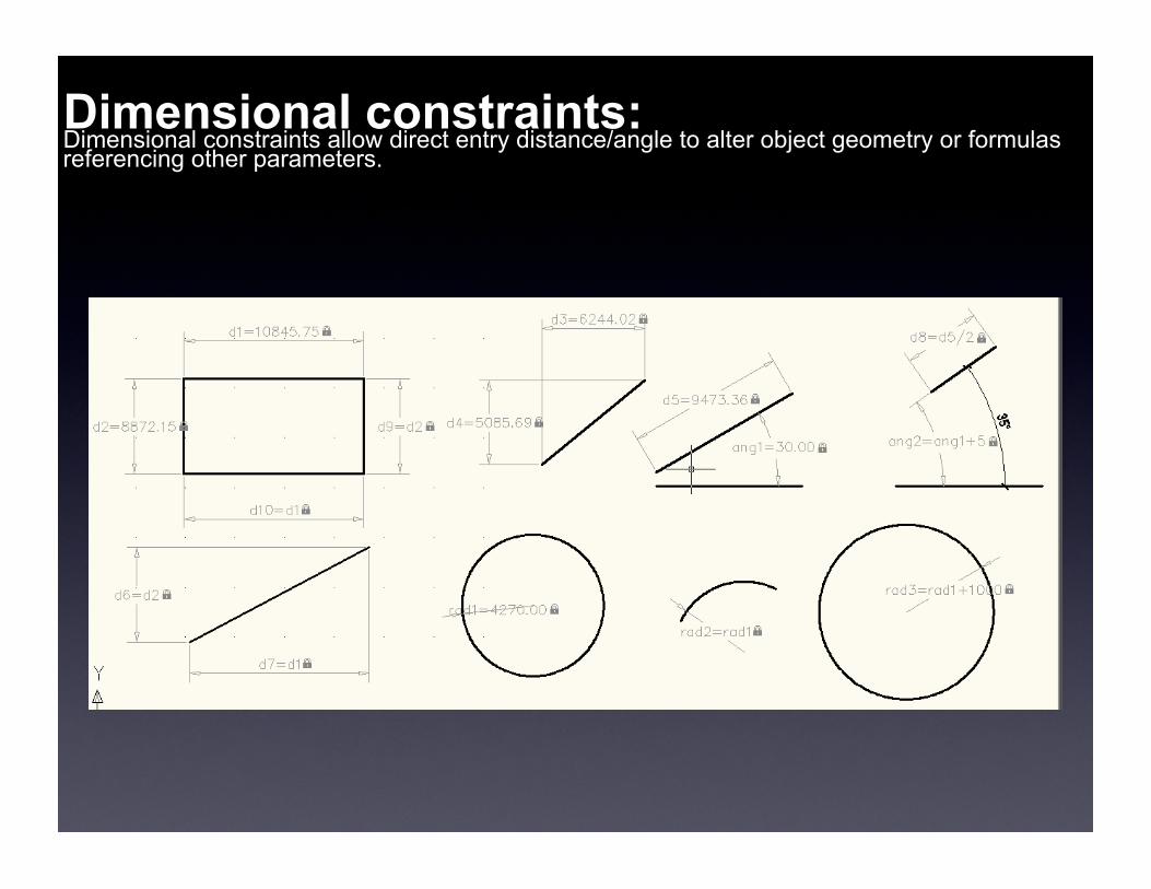
Dimensional constraints: Dimensional constraints allow direct entry distance/angle to alter object geometry or formulas referencing other parameters.

The rectangle below has a direct entered length parameter, d1=7, and a formula, d1/2, for the height. Alter d1 and the height will adjust to follow. The process of adding constraints is very similar to adding the dimensions they resemble. Names d1,2...etc are assigned automatically but can be edited afterwards if you wish. If constrained objects are copied new parameters are created for the new object. A copy of this rectangle would have d3=7 and d4=d3/2.

Why Parametric?
The applications of Parametrics are limitless but one simple example shows how they can change the behaviour of an AutoCAD object. Below you see two objects created with the veteran Rectangle tool. It's always been a bit of a fib as just creates a simple 4 node closed Polyline in the shape of a rectangle. Move a corner grip, as seen on the left, and you find your "rectangle" rapidly becomes rather un-rectangular! On the right, the same geometry has constraints applied to keep it rectangular as the corners are grip edited. The combination of parallel, perpendicular and horizontal constraints is indicatted by control icons you can toggle on/off or use to edit the constraint. As sharing files with parametrics becomes more common a good first step will be to toggle on the display of these indicators to check the configuration.