cac-fact sheets - druckluft effizient · cac-fact sheets (documents are in pdf format.) fact sheets...
TRANSCRIPT
CAC-Fact Sheets (Documents are in PDF format.)
Fact Sheets
FactSheet 1 Assessing Compressed Air Needs
Fact Sheet 2 Inappropriate Uses of Compressed Air
Fact Sheet 3 Compressed Air System Audits
Fact Sheet 4 Pressure Drop & Controlling System Pressure
Fact Sheet 5 Maint. of CA Systems for Peak Performance
Fact Sheet 6 Compressed Air System Controls
Fact Sheet 7 Compressed Air System Leaks
Fact Sheet 8 Packaged Compressor Efficiency Ratings
Fact Sheet 9 Compressed Air System Economics
Fact Sheet 10 Heat Recovery with Compressed Air Systems
Fact Sheet 11 Proven opportunities at the Component Level
This section is in progress.
For more information on the Compressed Air Challenge, call1-800-862-2086.
BACK TO TOP
WHAT| WHY| WHERE| WHO| HOW| TRAINING & REGISTRATION | HOME
© 1999 Compressed Air Challenge. All rights reserved.
1 of 1 03.04.01 15:45
Compressed Air Challenge, Get Smart About Compressed Air http://www.knowpressure.org/html/updates.htm
Improving Compressed Air System Performance F1-1A Sourcebook for Industry April 1998 - Rev. 0
Assessing Compressed Air Needs
Compressed Air Systems Fact Sheet #1
C o m p r e s s e
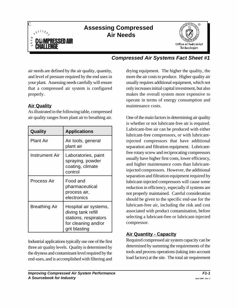
air needs are defined by the air quality, quantity, drying equipment. The higher the quality, theand level of pressure required by the end uses in more the air costs to produce. Higher quality airyour plant. Assessing needs carefully will ensure usually requires additional equipment, which notthat a compressed air system is configured only increases initial capital investment, but alsoproperly. makes the overall system more expensive to
Air Quality maintenance costs.As illustrated in the following table, compressedair quality ranges from plant air to breathing air. One of the main factors in determining air quality
Quality Applications
Plant Air Air tools, generalplant air
Instrument Air Laboratories, paintspraying, powdercoating, climatecontrol
Process Air Food andpharmaceuticalprocess air,electronics
Breathing Air Hospital air systems,diving tank refillstations, respiratorsfor cleaning and/orgrit blasting
Industrial applications typically use one of the firstthree air quality levels. Quality is determined bythe dryness and contaminant level required by theend-uses, and is accomplished with filtering and
operate in terms of energy consumption and
is whether or not lubricant-free air is required.Lubricant-free air can be produced with eitherlubricant-free compressors, or with lubricant-injected compressors that have additionalseparation and filtration equipment. Lubricant-free rotary screw and reciprocating compressorsusually have higher first costs, lower efficiency,and higher maintenance costs than lubricant-injected compressors. However, the additionalseparation and filtration equipment required bylubricant-injected compressors will cause somereduction in efficiency, especially if systems arenot properly maintained. Careful considerationshould be given to the specific end-use for thelubricant-free air, including the risk and costassociated with product contamination, beforeselecting a lubricant-free or lubricant-injectedcompressor.
Air Quantity - CapacityRequired compressed air system capacity can bedetermined by summing the requirements of thetools and process operations (taking into accountload factors) at the site. The total air requirement
Assessing Compressed Air Needs
Improving Compressed Air System Performance F1-2A Sourcebook for Industry April 1998 - Rev. 0
is not the sum of the maximum requirements for profile. The variation of demand for air over timeeach tool and process, but the sum of the average is a major consideration in system design. Plantsair consumption of each. High short-term with wide variations in air demand need a systemdemands should be met by air stored in an air that operates efficiently under part-load. Multiplereceiver. Systems may have more than one air compressors with sequencing controls mayreceiver. Strategically locating air receivers near provide more economical operation in such asources of high demand can also be effective. In case. Plants with a flatter load profile can usemost cases, a thorough evaluation of system simpler control strategies.demand may result in a control strategy that willmeet system demand with reduced overall Artificial Demandcompressor capacity. Artificial demand is defined as the excess volume
Oversized air compressors are extremely a result of supplying higher pressure thaninefficient because most systems use more energy necessary for applications. Flow controllers (seeper unit volume of air produced when operating the Fact Sheet titled Compressed Air Systemat part-load. In many cases it makes sense to Controls) can help to minimize artificial demand.use multiple, smaller compressors withsequencing controls to allow for efficientoperation at times when demand is less thanpeak.
If a system is properly designed and maintained and process operation pressure requirementsbut is still experiencing capacity problems, an should be specified by the process engineers.alternative to adding another compressor is to re- Required pressure levels must take into accountexamine the use of compressed air for certain system losses from dryers, separators, filters, andapplications. For some tasks, blowers or electric piping. A rule of thumb is that every 2 psitools may be more effective or appropriate. See increase in operating pressure requires anthe Fact Sheet titled Inappropriate Uses of additional 1% in operating energy costs.Compressed Air for more information on thissystem improvement opportunity. See the Fact Sheet titled Pressure Drop and
Load Profile ways to reduce system pressure and save energyAnother key to properly designing and operating while maintaining high performance.a compressed air system is assessing a plant’scompressed air requirements over time, or load
of air that is required by unregulated end uses as
PressureDifferent tools and process operations requiredifferent pressures. Pneumatic toolmanufacturers rate tools for specific pressures,
Controlling System Pressure for information on
Improving Compressed Air System Performance F2-1A Sourcebook for Industry April 1998 - Rev. 0
Inappropriate Uses of Compressed Air
Compressed Air Systems Fact Sheet #2
Compressed air is probably the most expensive C Use low pressure air instead of compressedform of energy available in a plant. Compressed air for blow guns, air lances, and agitation;air is also clean, readily-available, and simple-to- anduse. As a result, compressed air is often chosen • Use efficient electric motors for tools orfor applications in which other energy sources are actuators (although electric tools can havemore economical. Users should always consider less precise torque control, shorter lives, andmore cost-effective forms of power before lack the safety of compressed air poweredconsidering compressed air. tools).
Many operations can be accomplished more Other improper uses of compressed air areeconomically using alternative energy sources. unregulated end-uses and supply air toFor example, plants should: abandoned equipment, both of which are
C Use air conditioning or fans to cool electricalcabinets instead of compressed air vortex Unregulated End-Usestubes; A pressure regulator is used to limit maximum
C Apply a vacuum system instead of creating a distribution system just prior to the tool. If a toolvacuum using compressed air venturi operates without a regulator, it uses full systemmethods that flow high pressure air past an pressure. This results in increased system airorifice; demand and energy use, since the tool is using air
C Use blowers instead of compressed air to also increase equipment wear, resulting in higherprovide cooling, aspirating, agitating, mixing, maintenance costs and shorter tool life.or to inflate packaging;
C Use brushes, blowers, or vacuum systemsinstead of compressed air to clean parts orremove debris;
C Use blowers, electric actuators, or hydraulicsinstead of compressed air blasts to moveparts;
described below.
end-of-use pressure and is placed in the
at this higher pressure. High pressure levels can
Abandoned EquipmentMany plants undergo numerous equipmentconfiguration changes over time. In some cases,plant equipment is no longer used. Air flow tothis unused equipment should be stopped,preferably as far back in the distribution systemas possible without affecting operating equipment.

Inappropriate Uses of Compressed Air
Improving Compressed Air System Performance F2-2A Sourcebook for Industry April 1998 - Rev. 0
Using Compressed Air If compressed air is used for an application, theAs a general rule, compressed air should only be amount of air used should be of minimum quantityused if safety enhancements, significant and pressure and used for the shortest possibleproductivity gains, or labor reductions will result. duration of time. Compressed air use should alsoTypical overall efficiency is around 10%. be constantly monitored and re-evaluated.
Improving Compressed Air System Performance F3-1A Sourcebook for Industry April 1998 - Rev. 0
Compressed Air System Audits
Compressed Air Systems Fact Sheet #3
A compressed air system audit can highlight the performance due to system leaks, inappropriatetrue costs of compressed air and identify simple uses, demand events, poor system design, systemopportunities to improve efficiency and misuse, and total system dynamics are calculated,productivity. In some cases, the local electric and a written report with a recommended courseutility will help finance such an audit. of action is provided. Important aspects of a
Compressed air system users should consider below.using an independent auditor to examine theircompressed air system. Several firms exist that System Issuesspecialize in compressed air system audits. System issues go beyond examining theAudits are also performed by electric utilities, performance of an individual compressed airequipment distributors and manufacturers, energy system component and, instead, examine howservice companies, and engineering firms. An components on both the supply and demand sideinformed consumer should be aware that the of the system interact. Auditors typically addressquality and comprehensiveness of audits can a number of systems issues. These are discussedvary. Independent auditors should provide below, and many are addressed in more detail inrecommendations which are systems-neutral and other Compressed Air Systems Fact Sheets. commercially impartial. Independent auditorsshould neither specify nor recommend any Level of Air Treatment. The auditorparticular manufacturer’s products. typically examines the compressed air
A comprehensive compressed air system audit of air treatment required for proper operation ofshould include an examination of both air supply the equipment. Actual air quality levels are thenand usage and the interaction between the supply measured. If the air is not being treated enough,and demand. Auditors typically measure the alternative treatment strategies areoutput of a compressed air system, calculate recommended. If the air is being over-treatedenergy consumption in kilowatt-hours, and (an indication of energy being wasted),determine the annual cost of operating the recommendations are made to modify the system.system. The auditor may also measure total air In some cases, only certain end-use equipmentlosses due to leaks and locate those that are requires highly treated air, and the auditor maysignificant. All components of the compressed air recommend a system that allows for differentsystem are inspected individually and problem treatment levels at different points in the system.areas are identified. Losses and poor
basic compressed air system audit are discussed
applications and determines the appropriate level
Compressed Air System Audits
Improving Compressed Air System Performance F3-2A Sourcebook for Industry April 1998 - Rev. 0
Leaks. The auditor should identify and quantify Load Profile. Auditors typically estimate theleaks in the system and recommend a leak compressed air load profile in terms of how themanagement program. demand in cubic feet per minute (cfm) changes
over time. A facility with a varying load profilePressure Levels. An auditor also typically will likely benefit from advanced controldetermines the lowest possible pressure level strategies. A facility with short periods of heavyrequired to operate production equipment demand may benefit from implementing storageeffectively. In many cases, system pressure can options.be lowered, thereby saving energy. Mostsystems have one or more critical applications To establish the load profile, an auditor willthat determine the minimum acceptable pressure measure system flow and pressure across thein the system. In some cases, the application of system under different demand conditions, whilededicated storage or differential reduction on the observing the loading effect on the existingcritical applications will allow a reduction in compressors. This may require a number ofoverall system pressure. measurements over a 24-hour period (or even
Controls. The existing control system is time. Some auditors may use data loggingevaluated to determine if it is appropriate for the equipment to obtain both demand and powersystem demand profile. Performance gains consumption profiles.available from operating the system in a differentmode or using an alternative control strategy End-Use Equipment. The equipment andshould be estimated. processes that use compressed air will also be
Heat Recovery. Auditors will identify such as specifying equipment that operates at apotential applications for the use of heat lower pressure will be made. An auditor mayrecovery, if it is not already being used. also recommend replacing existing compressed
Demand Side Issues a source of energy other than compressed airThe demand side of the system refers to how (see the Fact Sheet titled Inappropriate Uses ofcompressed air is actually used in the plant. Compressed Air). Critical pressure applications
Distribution System. The overall layout of modifications may be recommended.the distribution system (piping) is examined.Pressure drop and efficiency are measured or Supply Side Issuesestimated, and the effectiveness of the The supply side refers to how the compressed aircondensate removal system is evaluated. Simple is generated and treated.changes that can enhance system performanceare suggested if appropriate. Compressor Package. The compressors
several days) if demand varies significantly over
examined. In some cases, recommendations
air-powered equipment with equipment that uses
are examined in detail. Local storage and other
are evaluated in terms of appropriateness for the
Compressed Air System Audits
Improving Compressed Air System Performance F3-3A Sourcebook for Industry April 1998 - Rev. 0
application and general appearance and Automatic Drains. Location, application,condition. Compressor efficiency is usually and effectiveness of both supply-side andestimated based on manufacturer-supplied data, demand-side drains are evaluated andcorrected to site conditions. The installation is alternatives recommended if necessary.also evaluated in terms of its location, connectionto cooling water, and ventilation. A general Air Receiver/Storage. The effectiveness ofappraisal and any recommendations for the receiver tank is evaluated in terms of locationalternative systems are also made. and size, and the receiver drain trap is examined
Filters. Filters are examined for cleanliness and solutions to control demand events should also besuitability for the application. Pressure drop investigated.across the filters is measured to estimate energylosses from the filter. A maintenance schedule for More Comprehensive Evaluationschanging the filters, and possibly higher System audits are designed to identify systemperformance filters, may be recommended. inefficiencies. If a system is found to be poorly
Aftercooler. Aftercooler and separator in need of substantial retrofit, a more detailedefficiency, cooling effectiveness, and condensate analysis of the system may be recommended.separation effectiveness are all measured andevaluated, and feasible modifications or A comprehensive evaluation may also includealternative systems are recommended. extensive measurements and analysis of supply
Dryer. Dryer appropriateness is assessed prepare a detailed systems flow diagram. Abased on the facility’s end-use applications. financial evaluation may also be performed,Dryer size, pressure drop, and efficiency are including current and proposed costs aftermeasured and evaluated. Modifications and retrofits are taken.replacements are recommended if needed.
to see if it is operating properly. Storage
designed, in unsatisfactory operating condition, or
and demand interactions. Some auditors will also
Improving Compressed Air System Performance F4-1A Sourcebook for Industry April 1998 - Rev. 0
Pressure Drop and Controlling System Pressure
Compressed Air Systems Fact Sheet #4
Pressure drop is a term used to characterize the and precautionary measures taken. The controlreduction in air pressure from the compressor range pressure setting must be reduced to allowdischarge to the actual point of use. Pressure for actual and potentially increasing pressure dropdrop occurs as the compressed air travels across the dryers and filters. Provision also mustthrough the treatment and distribution system. A be made to prevent exceeding the maximumproperly designed system should have a pressure allowable discharge pressure and drive motorloss of much less than 10% of the compressor’s amps of each compressor in the system.discharge pressure, measured from the receivertank output to the point of use. Pressure drop in the distribution system and in
Excessive pressure drop will result in poor results in lower operating pressure at the points ofsystem performance and excessive energy use. If the point of use operating pressure has toconsumption. Flow restrictions of any type in a be increased, try reducing the pressure drops insystem require higher operating pressures than the system before adding capacity or increasingare needed, resulting in higher energy the system pressure. Increasing the compressorconsumption. Minimizing differentials in all parts discharge pressure or adding compressorof the system is an important part of efficient capacity results in significant increases in energyoperation. Pressure drop upstream of the consumption.compressor signal requires higher compressionpressures to achieve the control settings on the Elevating system pressure increases unregulatedcompressor. The most typical problem areas uses such as leaks, open blowing and productioninclude the aftercooler, lubricant separators, and applications without regulators or with wide opencheck valves. This particular pressure rise regulators. The added demand at elevatedresulting from resistance to flow can involve pressure is termed "artificial demand", andincreasing the drive energy on the compressor by substantially increases energy consumption.1% of the connected power for each 2 psi of Instead of increasing the compressor dischargedifferential. pressure or adding additional compressorAn air compressor capacity control pressure capacity, alternative solutions should be sought,signal normally is located at the discharge of the such as reduced pressure drop, strategiccompressor package. When the signal location is compressed air storage, andmoved downstream of the compressed air dryers demand/intermediate controls. Equipment shouldand filters, to achieve a common signal for all be specified and operated at the lowest efficientcompressors, some dangers must be recognized operating pressure.
hoses and flexible connections at points of use
Pressure Drop and Reducing System Pressure
Improving Compressed Air System Performance F4-2A Sourcebook for Industry April 1998 - Rev. 0
What Causes Pressure Drop? than on the components at fault. The correctAny type of obstruction, restriction or roughness diagnosis requires pressure measurements atin the system will cause resistance to air flow and different points in the system to identify thecause pressure drop. In the distribution system, component(s) causing the high pressure drop. Inthe highest pressure drops usually are found at this case, the filter/regulator size needs to bethe points of use, including in undersized or increased, not the piping.leaking hoses, tubes, disconnects, filters,regulators and lubricators (FRLs). On the supply Minimizing Pressure Dropside of the system, air/lubricant separators, Minimizing pressure drop requires a systemsaftercoolers, moisture separators, dryers and approach in design and maintenance of thefilters are the main items causing significant system. Air treatment components, such aspressure drops. aftercoolers, moisture separators, dryers, and
The maximum pressure drop from the supply side pressure drop at specified maximum operatingto the points of use will occur when the conditions. When installed, the recommendedcompressed air flow rate and temperature are maintenance procedures should be followed andhighest. System components should be selected documented. Additional ways to minimizebased upon these conditions and the pressure drop are as follows:manufacturer of each component should berequested to supply pressure drop information C Properly design the distribution system.under these conditions. When selecting filters,remember that they will get dirty. Dirt loading C Operate and maintain air filtering andcharacteristics are also an important selection drying equipment to reduce the effects ofcriteria. Large end-users that purchase moisture, such as pipe corrosion.substantial quantities of components should workwith their suppliers to ensure that products meet C Select aftercoolers, separators, dryersthe desired specifications for differential pressure and filters having the least possibleand other characteristics. pressure drop for the rated conditions.
The distribution piping system often is diagnosed C Reduce the distance the air travelsas having a high pressure drop because a point of through the distribution system.use pressure regulator cannot sustain the requireddownstream pressure. If such a regulator is set at C Specify pressure regulators, lubricators,85 psig and the regulator and/or the upstream hoses, and connections having the bestfilter has a pressure drop of 20 psi, the system performance characteristics at the lowestupstream of the filter and regulator would have to pressure differential.maintain at least 105 psig. The 20 psi pressure
drop may be blamed on the system piping rather
filters, should be selected with the lowest possible
Pressure Drop and Reducing System Pressure
Improving Compressed Air System Performance F4-3A Sourcebook for Industry April 1998 - Rev. 0
Controlling System Pressure the pressure at points of use to fall belowMany plant air compressors operate with a full minimum requirements, which can causeload discharge pressure of 100 psig and an equipment to function improperly. Theseunload discharge pressure of 110 psig or higher. problems can be avoided with careful matching ofMany types of machinery and tools can operate system components, controls, and compressedefficiently with an air supply at the point of use of air storage capacity and location (see the Fact80 psig or lower. If the air compressor discharge Sheet titled Compressed Air System Controls).pressure can be reduced, significant savings canbe achieved. Check with the compressor For applications using significant amounts ofmanufacturer for performance specifications at compressed air, it is recommended thatdifferent discharge pressures. equipment be specified to operate at lower
Demand controls require sufficient pressure drop such as larger air cylinders, usually will befrom the primary air receiver into which the recouped quickly from resulting energy savings.compressor discharges, but the plant header Production engineers often specify end-usepressure can be controlled to a much narrower equipment to operate at an average systempressure range, shielding the compressor from pressure. This results in higher system operatingsevere load swings. Reducing and controlling the costs. Firstly, the point of use installationsystem pressure downstream of the primary components such as hoses, pressure regulators,receiver can result in a reduction in energy and filters will be installed between the systemconsumption of up to 10% or more, even though pressure and the end-use equipment pressure.the compressors discharge pressure has not been Secondly, filters will get dirty and leaks willchanged. occur. Both result in lower end-use pressure.
Reducing system pressure also can have a available end-use pressure.cascading effect in improving overall systemperformance, reducing leakage rates, and helping If an individual application requires a higherwith capacity and other problems. Reduced pressure, instead of raising the operating pressurepressure also reduces stress on components and of the whole system it may be best to replace oroperating equipment. However, a reduced modify this application. It may be possible tosystem operating pressure may require have a cylinder bore increased, gear ratios maymodifications to other components, including be changed, mechanical advantage improved, orpressure regulators, filters, and the size and a larger air motor may be used. The cost of thelocation of compressed air storage. improvements probably will be insignificant
Lowering average system pressure requires from operating the system at the lower pressure.caution since large changes in demand can cause
pressure levels. The added cost of components,
This should be anticipated in specifying the
compared with the energy reduction achieved
Pressure Drop and Reducing System Pressure
Improving Compressed Air System Performance F4-4A Sourcebook for Industry April 1998 - Rev. 0
It is also important to check if manufacturers are but it could be much higher in poorly designedincluding pressure drops in filters, pressure and maintained systems.regulators, and hoses in their pressurerequirements for end-use equipment, or if the When demand pressure has been successfullypressure requirements as stated are for after reduced and controlled, attention then should bethose components. A typical pressure differential turned to the compressor control set points tofor a filter, pressure regulator, and hose is 7 psid, obtain more efficient operation, and also to
possible unloading or shutting off of a compressorto further reduce energy consumption.
Improving Compressed Air System Performance F5-1A Sourcebook for Industry April 1998 - Rev. 0
Maintenance of Compressed AirSystems for Peak Performance
Compressed Air Systems Fact Sheet #5
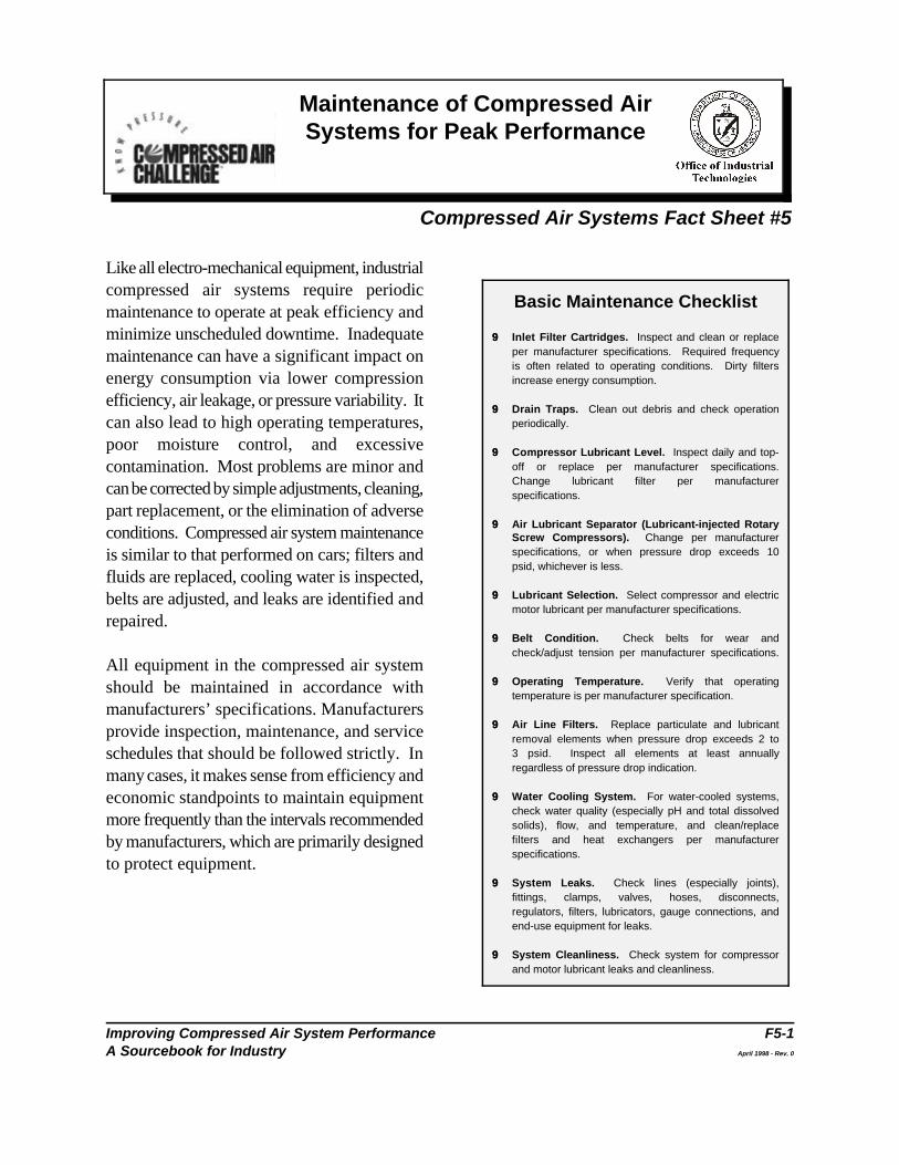
Basic Maintenance Checklist
99 Inlet Filter Cartridges. Inspect and clean or replaceper manufacturer specifications. Required frequencyis often related to operating conditions. Dirty filtersincrease energy consumption.
99 Drain Traps. Clean out debris and check operationperiodically.
99 Compressor Lubricant Level. Inspect daily and top-off or replace per manufacturer specifications.Change lubricant filter per manufacturerspecifications.
99 Air Lubricant Separator (Lubricant-injected RotaryScrew Compressors). Change per manufacturerspecifications, or when pressure drop exceeds 10psid, whichever is less.
99 Lubricant Selection. Select compressor and electricmotor lubricant per manufacturer specifications.
99 Belt Condition. Check belts for wear andcheck/adjust tension per manufacturer specifications.
99 Operating Temperature. Verify that operatingtemperature is per manufacturer specification.
99 Air Line Filters. Replace particulate and lubricantremoval elements when pressure drop exceeds 2 to3 psid. Inspect all elements at least annuallyregardless of pressure drop indication.
99 Water Cooling System. For water-cooled systems,check water quality (especially pH and total dissolvedsolids), flow, and temperature, and clean/replacefilters and heat exchangers per manufacturerspecifications.
99 System Leaks. Check lines (especially joints),fittings, clamps, valves, hoses, disconnects,regulators, filters, lubricators, gauge connections, andend-use equipment for leaks.
99 System Cleanliness. Check system for compressorand motor lubricant leaks and cleanliness.
Like all electro-mechanical equipment, industrialcompressed air systems require periodicmaintenance to operate at peak efficiency andminimize unscheduled downtime. Inadequatemaintenance can have a significant impact onenergy consumption via lower compressionefficiency, air leakage, or pressure variability. Itcan also lead to high operating temperatures,poor moisture control, and excessivecontamination. Most problems are minor andcan be corrected by simple adjustments, cleaning,part replacement, or the elimination of adverseconditions. Compressed air system maintenanceis similar to that performed on cars; filters andfluids are replaced, cooling water is inspected,belts are adjusted, and leaks are identified andrepaired.
All equipment in the compressed air systemshould be maintained in accordance withmanufacturers’ specifications. Manufacturersprovide inspection, maintenance, and serviceschedules that should be followed strictly. Inmany cases, it makes sense from efficiency andeconomic standpoints to maintain equipmentmore frequently than the intervals recommendedby manufacturers, which are primarily designedto protect equipment.
Maintenance of Compressed Air Systems for Peak Performance
Improving Compressed Air System Performance F5-2A Sourcebook for Industry April 1998 - Rev. 0
One way to tell if a system is being maintained The compressor lubricant and lubricant filter needwell and is operating properly is to periodically to be changed per manufacturer’s specification.benchmark the system by tracking power, Lubricant can become corrosive and degradepressure, and flow. If power use at a given both the equipment and system efficiency. pressure and flow rate goes up, the system’sefficiency is degrading. This bench marking willalso let you know if the compressor is operatinga full capacity, and if the capacity is decreasingover time. On new systems, specifications shouldbe recorded when the system is first set-up andoperating properly.
Maintenance issues for specific systemcomponents are discussed below.
Compressor PackageThe main areas of the compressor package inneed of maintenance are the compressor, heatexchanger surfaces, air lubricant separator,lubricant, lubricant filter, and air inlet filter.
The compressor and intercooling surfaces needto be kept clean and foul-free. If they are dirty,compressor efficiency will be adversely affected.Fans and water pumps should also be inspectedto ensure that they are operating at peakperformance.
The air lubricant separator in a lubricant-cooledrotary screw compressor generally starts with a2-3 psid pressure drop at full-load when new.Maintenance manuals usually suggest changingthem when there is about a 10 psid pressure dropacross the separator. In many cases it may makesense to make an earlier separator replacement,especially if electricity prices are high.
For lubricant-injected rotary compressors, thelubricant serves to lubricate bearings, gears, andintermeshing rotor surfaces. The lubricant alsoacts as a seal and removes most of the heat ofcompression. Only a lubricant meeting themanufacturer=s specifications should be used.
Inlet filters and inlet piping also need to be keptclean. A dirty filter can reduce compressorcapacity and efficiency. Filters should bemaintained at least per manufacturer’sspecifications, taking into account the level ofcontaminants in the facility’s air.
Compressor DrivesIf the electric motor driving a compressor is notproperly maintained, it will not only consumemore energy, but be apt to fail before itsexpected lifetime. The two most importantaspects of motor maintenance are lubrication andcleaning.
Lubrication. Too much lubrication can be justas harmful as too little and is a major cause ofpremature motor failure. Motors should belubricated per the manufacturer’s specification,which can be anywhere from every 2 months toevery 18 months, depending on annual hours ofoperation and motor speed. On motors withbearing grease fittings, the first step in lubricationis to clean the grease fitting and remove the drainplug. High quality new grease should be added,
Maintenance of Compressed Air Systems for Peak Performance
Improving Compressed Air System Performance F5-3A Sourcebook for Industry April 1998 - Rev. 0
and the motor should be run for about an hour drain trap stuck in the closed position will causebefore the drain plug is replaced. This allows condensate to backup and be carriedexcess grease to be purged from the motor downstream where it can damage other systemwithout dripping on the windings and damaging components. Traps stuck in the open positionthem. can be a major source of wasted energy in some
Cleaning. Since motors need to dissipate heat,it is important to keep all of the air passages clean End-Use Filters, Regulators, and and free of obstruction. For enclosed motors, it Lubricatorsis vital that cooling fins are kept free of debris. Point-of-use filters, regulators, and lubricators arePoor motor cooling can increase motor needed to ensure that a tool is receiving a clean,temperature and winding resistance, which lubricated supply of air at the proper pressure.shortens motor life and increases energy Filters should be inspected periodically becauseconsumption. a clogged filter will increase pressure drop, which
Belts. Motor v-belt drives also require periodic increase the pressure required from themaintenance. Tight belts can lead to excessive compressor, thereby consuming excessivebearing wear, and loose belts can slip and waste energy. A filter that is not operating properly willenergy. Under normal operation, belts stretch also allow contaminants into a tool, causing it toand wear and, therefore, require adjustment. A wear out prematurely. The lubricant level shouldgood rule-of-thumb is to examine and adjust belts also be checked often enough to ensure that itafter every 400 hours of operation. does not run dry. Tools that are not properly
Air Treatment Equipment energy. Fouled compressed air treatment equipment canresult in excessive energy consumption as well as Leakspoor-quality air that can damage other Leak detection and repair is an important part ofequipment. All filters should be kept clean. any maintenance program. For more informationDryers, aftercoolers, and separators should all be on finding and fixing leaks, see the Fact Sheetcleaned and maintained per manufacturer’s titled Compressed Air System Leaks.specifications.
Automatic Drain Traps maintenance program and strictly following it isMost compressed air systems have numerous critical to maintaining the performance of amoisture traps located throughout the system. compressed air system. One person should beTraps need to be inspected periodically to ensure given the responsibility of ensuring that allthat they are not stuck in either the open or maintenance is performed properly, on schedule,closed position. An automatic drain trap stuck in and adequately documented.the open position will leak compressed air; a
plants.
can either reduce pressure at the point of use or
lubricated will wear prematurely and use excess
Establishing a regular, well-organized
Average SystemHeader PressurewithImpreciseCompressorControl
Average SystemHeader Pressurewith PreciseCompressorControl
80 psi MinimumSystem HeaderPressure
75
80
85
90
95
100
105
Timepsi
Improving Compressed Air System Performance F6-1A Sourcebook for Industry April 1998 - Rev. 0
Compressed Air System Controls
Compressed Air Systems Fact Sheet #6
Impacts of Controls on System Pressure
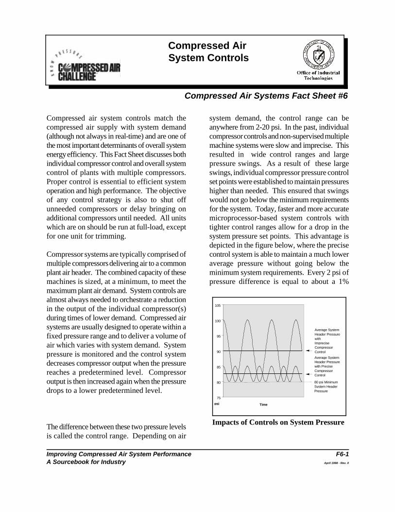
Compressed air system controls match the system demand, the control range can becompressed air supply with system demand anywhere from 2-20 psi. In the past, individual(although not always in real-time) and are one of compressor controls and non-supervised multiplethe most important determinants of overall system machine systems were slow and imprecise. Thisenergy efficiency. This Fact Sheet discusses both resulted in wide control ranges and largeindividual compressor control and overall system pressure swings. As a result of these largecontrol of plants with multiple compressors. swings, individual compressor pressure controlProper control is essential to efficient system set points were established to maintain pressuresoperation and high performance. The objective higher than needed. This ensured that swingsof any control strategy is also to shut off would not go below the minimum requirementsunneeded compressors or delay bringing on for the system. Today, faster and more accurateadditional compressors until needed. All units microprocessor-based system controls withwhich are on should be run at full-load, except tighter control ranges allow for a drop in thefor one unit for trimming. system pressure set points. This advantage is
Compressor systems are typically comprised of control system is able to maintain a much lowermultiple compressors delivering air to a common average pressure without going below theplant air header. The combined capacity of these minimum system requirements. Every 2 psi ofmachines is sized, at a minimum, to meet the pressure difference is equal to about a 1%maximum plant air demand. System controls arealmost always needed to orchestrate a reductionin the output of the individual compressor(s)during times of lower demand. Compressed airsystems are usually designed to operate within afixed pressure range and to deliver a volume ofair which varies with system demand. Systempressure is monitored and the control systemdecreases compressor output when the pressurereaches a predetermined level. Compressoroutput is then increased again when the pressuredrops to a lower predetermined level.
The difference between these two pressure levelsis called the control range. Depending on air
depicted in the figure below, where the precise
Compressed Air System Controls
Improving Compressed Air System Performance F6-2A Sourcebook for Industry April 1998 - Rev. 0
change in energy consumption. Narrower it does not deliver air for periods of time.variations in pressure not only use less energy, Modulating inlet and multi-step controls allow thebut avoid negative effects on production quality compressor to operate at part-load and deliver acontrol. reduced amount of air during periods of reduced
Caution needs to be taken when loweringaverage system header pressure because large, Start/Stop. Start/stop is the simplest controlsudden changes in demand can cause the available and can be applied to eitherpressure to drop below minimum requirements, reciprocating or rotary screw compressors. Theleading to improper functioning of equipment. motor driving the compressor is turned on or offWith careful matching of system controls and in response to the discharge pressure of thestorage capacity, these problems can be avoided. machine. Typically, a simple pressure switch
Few air systems operate at full-load all of the control should not be used in an application thattime. Part-load performance is therefore critical, has frequent cycling because repeated starts willand is primarily influenced by compressor type cause the motor to overheat and otherand control strategy. compressor components to require more frequent
Controls and System Performance only used for applications with very low dutyThe type of control specified for a given system cycles.is largely determined by the type of compressorbeing used and the facility’s demand profile. If a Load/Unload. Load/unload control, alsosystem has a single compressor with a very known as constant speed control, allows thesteady demand, a simple control system may be motor to run continuously, but unloads theappropriate. On the other hand, a complex compressor when the discharge pressure issystem with multiple compressors, varying adequate. Compressor manufacturers usedemand, and many types of end-uses will require different strategies for unloading a compressor,a more sophisticated strategy. In any case, but in most cases, an unloaded rotary screwcareful consideration should be given to both compressor will consume 15-35% of full-loadcompressor and system control selection because horsepower while delivering no useful work. Asthey can be the most important factors affecting a result, some load/unload control schemes cansystem performance and efficiency. be inefficient.
Individual Compressor Control Modulating Controls. ModulatingStrategies (throttling) inlet control allows the output of aOver the years, compressor manufacturers have compressor to be varied to meet flowdeveloped a number of different types of control requirements. Throttling is usually accomplishedstrategies. Controls such as start/stop and by closing down the inlet valve, therebyload/unload respond to reductions in air demand, restricting inlet air to the compressor. Thisincreasing compressor discharge pressure by control scheme is applied to centrifugal andturning the compressor off or unloading it so that rotary screw compressors. This control method,
demand.
provides the motor start/stop signal. This type of
maintenance. This control scheme is typically
Compressed Air System Controls
Improving Compressed Air System Performance F6-3A Sourcebook for Industry April 1998 - Rev. 0
when applied to displacement compressors, is an By definition, system controls orchestrate theinefficient means of varying compressor output. actions of the multiple individual compressors thatWhen used on centrifugal compressors, more supply air to the system. Prior to the introductionefficient results are obtained, particularly with the of automatic system controls, compressoruse of inlet guide vanes which direct the air in the systems were set by a method known assame direction as the impeller inlet. The amount cascading set points. Individual compressorof capacity reduction is limited by the potential operating pressure set points were established tofor surge and minimum throttling capacity. either add or subtract compressor capacity to
Multi-step (Part-load) Controls. Somecompressors are designed to operate in two ormore partially-loaded conditions. With such acontrol scheme, output pressure can be closelycontrolled without requiring the compressor tostart/stop or load/unload.
Reciprocating compressors are designed as two-step (start/stop or load/unload), three- step (0%,50%, 100%) or five-step (0%, 25%, 50%, 75%,100%) control. These control schemes generallyexhibit an almost direct relationship betweenmotor power consumption and loaded capacity.
Some rotary screw compressors can vary their used to regulate systems by sequencing or stagingcompression volumes (ratio) using sliding or turn individual compressor capacity to meet systemvalves. These are generally applied in demand. Sequencers are referred to as singleconjunction with modulating inlet valves to master control units because all compressorprovide more accurate pressure control with operating decisions are made and directed fromimproved part-load efficiency. the master unit. Sequencers control compressor
Variable Frequency Drives. Historically, on- and off-line in response to monitored systemthe use of variable frequency drives (VFDs) for pressure (demand). The control system typicallyindustrial air compressors has been rare, because offers a higher efficiency because the controlthe high initial cost of a VFD could not justify the range around the system target pressure is tighter.efficiency gain over other control schemes. Cost This tighter range allows for a reduction inis no longer a major issue. VFDs may gain average system pressure. Again, caution needsacceptance in compressor applications as they to be taken when lowering average systembecome more reliable and efficient at full-load. header pressure because large, sudden changes
System Controls minimum requirements, leading to improper
meet system demand. The additive nature of thisstrategy results in large control ranges as depictedin the figure on the first page of this Fact Sheet.
The objective of an effective automatic systemcontrol strategy is to match system demand withcompressors operated at or near their maximumefficiency levels. This can be accomplished in anumber of ways, depending on fluctuations indemand, available storage, and the characteristicsof the equipment supplying and treating thecompressed air.
Single Master (Sequencing) Controls.Sequencers are, as the name implies, devices
systems by taking individual compressor capacity
in demand can cause the pressure to drop below
functioning of equipment. With careful
Compressed Air System Controls
Improving Compressed Air System Performance F6-4A Sourcebook for Industry April 1998 - Rev. 0
matching of system controls and storage capacity, demand side. This allows compressors to bethese problems can be avoided (see also flow operated at or near their optimum pressures forcontroller). maximum efficiency while the pressure on the
Multi-Master (Network) Controls. usage requirements. Storage, sized to meetNetwork controls offer the latest in system anticipated fluctuations in demand, is an essentialcontrol. It is important that these controllers be part of this control strategy. Higher pressureused to shut down any compressors running supply air enters a storage tank at aunnecessarily. They also allow the operating predetermined rate and is available to reliablycompressors to function in a more efficient mode. meet fluctuations in demand at a constant, lowerControllers used in networks are combination pressure level. A well designed and managedcontrollers. They provide individual compressor system integrates control strategy, demandcontrol as well as system control functions. The control, signal locations, differentials, compressorterm multi-master refers to the system control controls, and storage. The goal is to operatecapability within each individual compressor demand at the lowest possible pressure, supportcontroller. These individual controllers are linked transient events as much as possible with storedor networked together, thereby sharing all air, and take as long as possible to replenishoperating information and status. One of the storage. This should result in the lowest possiblenetworked controllers is designated as the leader. energy consumption.Because these controllers share information,compressor operating decisions with respect to Air Storage and Controlschanging air demand can be made more quickly Storage can be used to control demand eventsand accurately. The effect is a tight pressure (peak demand periods) in the system bycontrol range which allows a further reduction in reducing both the amount of pressure drop andthe air system target pressure. Although initial the rate of decay. Storage can be used tocosts for system controls are often high, these protect critical pressure applications from othercontrols are becoming more common because of events in the system. Storage can also be used tothe resulting reductions in operating costs. control the rate of pressure drop in demand while
Flow ControllersFlow controllers are system pressure or densitycontrols used in conjunction with the individualcompressor or system controls describedpreviously. A flow controller does not directlycontrol a compressor and is generally notincluded as part of a compressor package. Aflow controller is a device that serves to separatethe supply side of a compressor system from the
demand side can be reduced to minimize actual
supporting the speed of transmission responsefrom supply. For some systems, it is important toprovide a form of refill control such as a flowcontrol valve.
Many systems have a compressor operating inmodulation to support demand events, andsometimes strategic storage solutions can allowfor this compressor to be turned off.
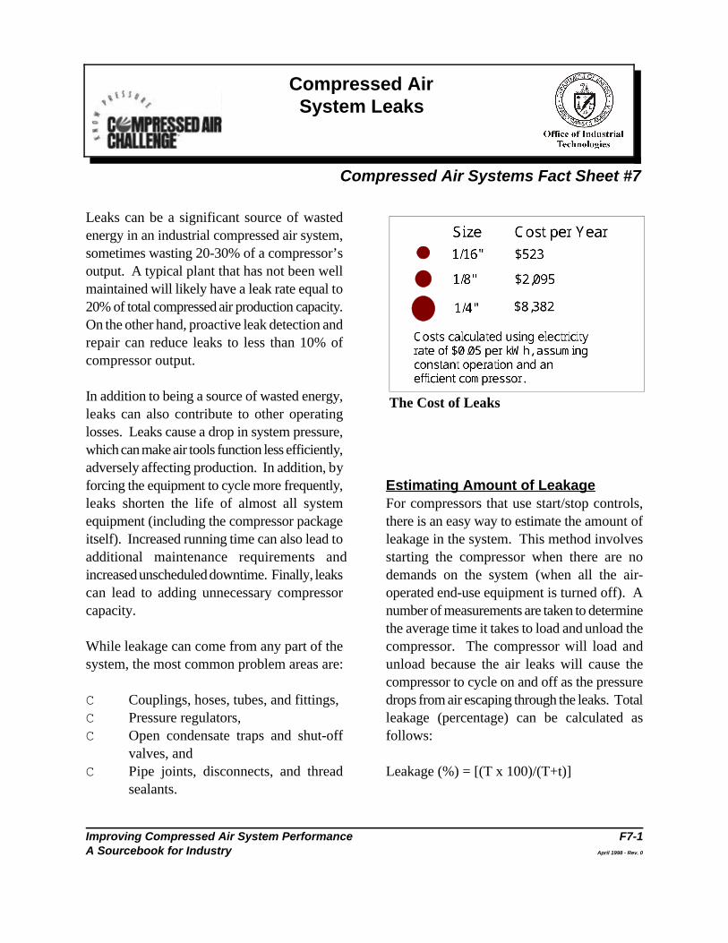
1/16" $523
1/8" $2,095
1/4" $8,382
Size Cost per Year
Costs calculated using electricity
rate of $0.05 per kWh, assuming
constant operation and an efficient
compressor.
Improving Compressed Air System Performance F7-1A Sourcebook for Industry April 1998 - Rev. 0
Compressed Air System Leaks
Compressed Air Systems Fact Sheet #7
The Cost of Leaks
Leaks can be a significant source of wastedenergy in an industrial compressed air system,sometimes wasting 20-30% of a compressor’soutput. A typical plant that has not been wellmaintained will likely have a leak rate equal to20% of total compressed air production capacity.On the other hand, proactive leak detection andrepair can reduce leaks to less than 10% ofcompressor output.
In addition to being a source of wasted energy,leaks can also contribute to other operatinglosses. Leaks cause a drop in system pressure,which can make air tools function less efficiently,adversely affecting production. In addition, byforcing the equipment to cycle more frequently, Estimating Amount of Leakageleaks shorten the life of almost all system For compressors that use start/stop controls,equipment (including the compressor package there is an easy way to estimate the amount ofitself). Increased running time can also lead to leakage in the system. This method involvesadditional maintenance requirements and starting the compressor when there are noincreased unscheduled downtime. Finally, leaks demands on the system (when all the air-can lead to adding unnecessary compressor operated end-use equipment is turned off). Acapacity. number of measurements are taken to determine
While leakage can come from any part of the compressor. The compressor will load andsystem, the most common problem areas are: unload because the air leaks will cause the
C Couplings, hoses, tubes, and fittings, drops from air escaping through the leaks. TotalC Pressure regulators, leakage (percentage) can be calculated asC Open condensate traps and shut-off follows:
valves, andC Pipe joints, disconnects, and thread Leakage (%) = [(T x 100)/(T+t)]
sealants.
the average time it takes to load and unload the
compressor to cycle on and off as the pressure
Compressed Air System Leaks
Improving Compressed Air System Performance F7-2A Sourcebook for Industry April 1998 - Rev. 0
where: T=on-load time (minutes) Leak Detectiont=off-load time (minutes) Since air leaks are almost impossible to see,
other methods must be used to locate them. The
Leakage will be expressed in terms of the acoustic detector, which can recognize the highpercentage of compressor capacity lost. The frequency hissing sounds associated with airpercentage lost to leakage should be less than leaks. These portable units consist of directional10% in a well-maintained system. Poorly microphones, amplifiers, maintained systems can have losses as high as and audio filters, and usually have either visual20-30% of air capacity and power. Leakage can indicators or earphones to detect leaks. Abe estimated in systems with other control simpler method is to apply soapy water with astrategies if there is a pressure gauge downstream paint brush to suspect areas. Although reliable,of the receiver. This method requires an estimate this method can be time consuming. of total system volume, including any downstream How to Fix Leakssecondary air receivers, air mains, and piping (V, Leaks occur most often at joints and connections.in cubic feet). The system is then started and Stopping leaks can be as simple as tightening abrought to the normal operating pressure (P1). connection or as complex as replacing faultyMeasurements should then be taken of the time equipment such as couplings, fittings, pipe(T) it takes for the system to drop to a lower sections, hoses, joints, drains, and traps. In manypressure (P2), which should be a point equal to cases leaks are caused by bad or improperlyabout one-half the operating pressure. applied thread sealant. Select high quality fittings,
Leakage can be calculated as follows: properly with appropriate thread sealant.
Leakage (cfm free air ) = Non-operating equipment can be an additional (V x (P1-P2)/T x 14.7) x 1.25 source of leaks. Equipment no longer in use
where: V is in cubic feet system.P1 and P2 are in psigT is in minutes Another way to reduce leaks is to lower the
The 1.25 multiplier corrects leakage to normal the pressure differential across an orifice or leak,system pressure, allowing for reduced leakage the lower the rate of flow, so reduced systemwith falling system pressure. Again, leakage of pressure will result in reduced leakage rates.greater than 10% indicates that the system can Stabilizing the system header pressure at itslikely be improved. These tests should be carried lowest practical range will minimize the leakageout quarterly as part of a regular leak detection rate for the system. For more information onand repair program. lowering system pressure, see the Fact Sheet
best way to detect leaks is to use an ultrasonic
disconnects, hose, tubing, and install them
should be isolated with a valve in the distribution
demand air pressure of the system. The lower
Compressed Air System Leaks
Improving Compressed Air System Performance F7-3A Sourcebook for Industry April 1998 - Rev. 0
titled Pressure Drop and Controlling System employee involvement. All facilities withPressure. compressed air systems should establish an
Once leaks have been repaired, the compressor involving decision-making representatives fromcontrol system should be re-evaluated to realize production should be formed.the total savings potential.
A Leak Prevention Program overall program aimed at improving theA good leak prevention program will include the performance of compressed air systems. Oncefollowing components: identification (including the leaks are found and repaired, the systemtagging), tracking, repair, verification, and should be re-evaluated.
aggressive leak program. A cross-cutting team
A leak prevention program should be part of an
Improving Compressed Air System Performance F8-1A Sourcebook for Industry April 1998 - Rev. 0
Packaged Compressor Efficiency Ratings
Compressed Air Systems Fact Sheet #8
Evaluating and comparing industrial air The following standards have been developed forcompressor capacities and efficiencies can be a measuring air compressor performance:daunting task. Standards exist for testing theperformance of a compressor, but they have not C CAGI/PNEUROP – Acceptance Test Codealways been applied in a consistent manner, and for Bare Displacement Air Compressorsperformance test results and efficiency ratings are (PN2CPTC1)not always published in consistent, standardformats. The result is that purchasers of air C CAGI/PNEUROP – Acceptance Test Codecompressors can find it difficult to compare the for Electrically-Driven Packagedequipment performance. Displacement Air Compressors
The Compressed Air and Gas Institute (CAGI),the primary compressed air industry trade C CAGI/PNEUROP – Acceptance Test Codeassociation, has developed performance testing for I.C. Engine-Driven Packagedstandards. CAGI, in conjunction with its Displacement Air CompressorsEuropean counterpart PNEUROP, has (PN2CPTC3)developed simplified performance testingstandards which have been incorporated as C American Society of Mechanical Engineersaddenda in International Standards Organization (ASME) – Power Test Code 9,(ISO) Standard ISO 1217, Displacement Displacement Compressors, Vacuum Pumps,Compressors Acceptance Tests. These and BlowersSimplified Test Codes were adopted by themembership of CAGI and will be reflected in C International Standards Organization (ISO)performance data published in manufacturers’ – ISO 1217, Displacement Compressorsliterature. Some CAGI members also have ISO Acceptance Tests [distributed in the United9001 Certification which requires documentation States by the American National Standardsof compliance with published performance and Institute (ANSI)]procedures. Compressed air system users should be aware The revised ISO 1217 with Simplified Testthat not all manufacturers marketing compressors Codes will likely be the most commonly usedin the United States are members of CAGI, and standard in the future. CAGI is also currentlysome may test their compressors using different developing Data Sheets outlining a commonstandards. format and style for reporting compressor
(PN2CPTC2)
Packaged Compressor Efficiency Ratings
Improving Compressed Air System Performance F8-2A Sourcebook for Industry April 1998 - Rev. 0
performance, including efficiency. For more C Manufacturers may test their compressorsinformation on CAGI Data Sheets, see Appendix under different “standard” conditions.B of this Sourcebook. Standard conditions should be at 14.5 psia
The industry norm for comparison of compressor humidity).efficiency is given in terms of bhp/100 acfm(brake horse power per actual cubic feet per C The actual full-load power required by aminute) at a compressor discharge pressure of typical air compressor package will exceed100 psig. A typical single-stage lubricant-injected the nominal nameplate rating of the mainrotary screw compressor will have a rating of drive electric motor. Such motors have aapproximately 22 bhp/100 acfm (referenced to continuous service factor, usually 15%, whichstandard inlet conditions). Users need to allows continuous operation at 15% aboveremember that performance at site conditions will the nominal rating. Most manufacturers usebe different from test data because of differences up to two thirds of the available servicein factors such as ambient temperature, pressure, factor, so that full-load power will be 10%and humidity. above the nominal motor rating. It is
Even when accurate, consistent efficiency the motor nameplate hp rating, wheninformation is available, it may only be specified comparing efficiency ratings in hp/acfm. Tofor full-load operation (i.e., full capacity and include the motor efficiency and all packagespecified full-load discharge pressure). Since accessories and losses, use a rating in totalmost systems operate at part-load much of the kW input per acfm to provide more precisetime, it is also important to compare part-load data. efficiencies when evaluating the performance ofdifferent compressors. The variety of control C Manufacturers may use a flange-to-flangemethods can, however, make this difficult. rating that does not include inlet, discharge,
When gathering information on compressor overall efficiency by 5% or more.performance and comparing different models,users should make sure the compressors have C Energy consumption for accessorybeen tested using the same standard, at the same components, such as cooling fan motors, mayconditions, and that the data is being reported in not be treated consistently.a consistent manner. Some situations can lead to“apples and oranges” comparisons. For C Manufacturers may apply ranges orexample: tolerances to performance data.
(1 bar); 68EF (20EC) and dry (0% relative
therefore important to use the bhp rating, not
and other package losses. This can affect
Packaged Compressor Efficiency Ratings
Improving Compressed Air System Performance F8-3A Sourcebook for Industry April 1998 - Rev. 0
C Performance is usually based on perfect Poor intercooling will adversely affectintercooling, which may not be realized under compressor performance.actual operating conditions. Perfectintercooling requires the air inlet temperature As the revised ISO standard and CAGIat each stage to be the same, requiring a Compressor Data Sheets become morecooling water temperature approximately commonly used, these equipment comparison15EF below the ambient air temperature. problems should become less significant.
Improving Compressed Air System Performance F9-1A Sourcebook for Industry April 1998 - Rev. 0
Compressed Air SystemEconomics
Compressed Air Systems Fact Sheet #9
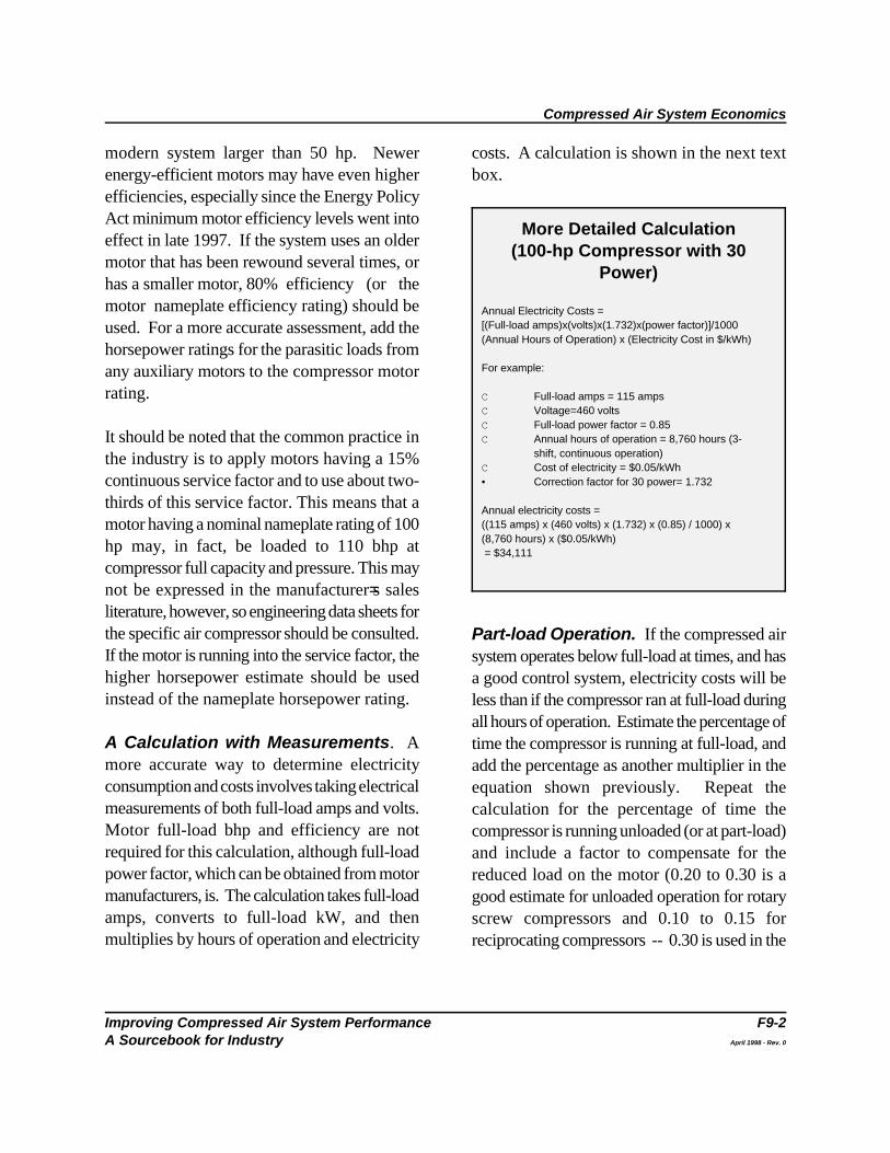
Simple Calculation(100 hp Compressor)
Annual Electricity Costs =(Motor full-load brake horsepower) x (0.746 kW/hp) x(1/0.9) x (Annual Hours of Operation) x (Electricity Cost in$/kWh)
For example:
C Motor full-load bhp = 100 hpC Annual hours of operation = 8,760 hours (3-shift,
continuous operation)C Full Cost of electricity = $0.05/kWh
Annual electricity costs = (100 hp) x (0.746 kW/hp) x (8,760 hours) x($0.05/kWh)/0.9 = $36,305
Delivering compressed air to a manufacturing A Simple Calculation. The following data isfacility is an expensive operation. Delivery needed for a quick calculation of electricity costsrequires costly equipment that consumes for a compressor operating at full-load:significant amounts of electricity and needsfrequent maintenance. In spite of this, many C Compressor motor nameplate rating (bhp),facilities have no idea how much their C Motor nameplate efficiency (or an estimate ofcompressed air systems cost on an annual basis, efficiency),or how much money they could save by C Annual hours of operation (hrs/year), andimproving the performance of these systems. C Cost of electricity ($/kWh).
Electricity costs are by far the largest expense of Annual electricity costs can be calculated byowning and operating a compressed air system. inserting this information into the equation in theThe initial cost for a 100-hp compressor is following text box:$30,000-$50,000, depending on the type ofcompressor and manufacturer, while annualelectricity charges for the same system can reach$50,000. Added to this are annual maintenancecosts, which can be 10% or more of the initialcost of the system.
This Fact Sheet presents a simple calculation toestimate annual electricity costs, and a moreaccurate calculation requiring electricalmeasurements.
Calculating Electricity CostsFull-load Operation. Even if an aircompressor is not separately metered, estimatingannual electricity cost is simple. For moreanalysis techniques, see the AIRMaster softwarereferenced in the Resource and Tools section, This equation assumes the electric motor drivingand/or call the Compressed Air Challenge™ the compressor is 90% efficient (the 90 in thenumber listed in the Directory section. 1/0.9 factor) -- a reasonable estimate for a
Compressed Air System Economics
Improving Compressed Air System Performance F9-2A Sourcebook for Industry April 1998 - Rev. 0
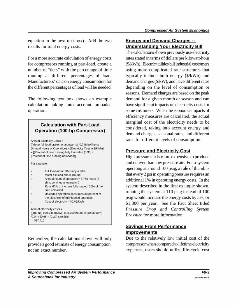
More Detailed Calculation(100-hp Compressor with 30
Power)
Annual Electricity Costs =[(Full-load amps)x(volts)x(1.732)x(power factor)]/1000(Annual Hours of Operation) x (Electricity Cost in $/kWh)
For example:
C Full-load amps = 115 ampsC Voltage=460 voltsC Full-load power factor = 0.85C Annual hours of operation = 8,760 hours (3-
shift, continuous operation)C Cost of electricity = $0.05/kWh• Correction factor for 30 power= 1.732
Annual electricity costs = ((115 amps) x (460 volts) x (1.732) x (0.85) / 1000) x(8,760 hours) x ($0.05/kWh) = $34,111
modern system larger than 50 hp. Newer costs. A calculation is shown in the next textenergy-efficient motors may have even higher box.efficiencies, especially since the Energy PolicyAct minimum motor efficiency levels went intoeffect in late 1997. If the system uses an oldermotor that has been rewound several times, orhas a smaller motor, 80% efficiency (or themotor nameplate efficiency rating) should beused. For a more accurate assessment, add thehorsepower ratings for the parasitic loads fromany auxiliary motors to the compressor motorrating.
It should be noted that the common practice inthe industry is to apply motors having a 15%continuous service factor and to use about two-thirds of this service factor. This means that amotor having a nominal nameplate rating of 100hp may, in fact, be loaded to 110 bhp atcompressor full capacity and pressure. This maynot be expressed in the manufacturer=s salesliterature, however, so engineering data sheets forthe specific air compressor should be consulted.If the motor is running into the service factor, thehigher horsepower estimate should be usedinstead of the nameplate horsepower rating.
A Calculation with Measurements. Amore accurate way to determine electricityconsumption and costs involves taking electricalmeasurements of both full-load amps and volts.Motor full-load bhp and efficiency are notrequired for this calculation, although full-loadpower factor, which can be obtained from motormanufacturers, is. The calculation takes full-loadamps, converts to full-load kW, and thenmultiplies by hours of operation and electricity
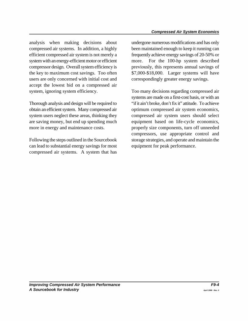
Part-load Operation. If the compressed airsystem operates below full-load at times, and hasa good control system, electricity costs will beless than if the compressor ran at full-load duringall hours of operation. Estimate the percentage oftime the compressor is running at full-load, andadd the percentage as another multiplier in theequation shown previously. Repeat thecalculation for the percentage of time thecompressor is running unloaded (or at part-load)and include a factor to compensate for thereduced load on the motor (0.20 to 0.30 is agood estimate for unloaded operation for rotaryscrew compressors and 0.10 to 0.15 forreciprocating compressors -- 0.30 is used in the
Compressed Air System Economics
Improving Compressed Air System Performance F9-3A Sourcebook for Industry April 1998 - Rev. 0
Calculation with Part-LoadOperation (100-hp Compressor)
Annual Electricity Costs =[(Motor full-load brake horsepower) x (0.746 kW/hp) x (Annual Hours of Operation) x (Electricity Cost in $/kWh)]x [(Percent of time running fully loaded) + (0.30) x(Percent of time running unloaded)]
For example:
• Full load motor efficiency = 90%C Motor full-load bhp = 100 hpC Annual hours of operation = 8,760 hours (3-
shift, continuous operation)C Runs 65% of the time fully loaded, 35% of the
time unloadedC Unloaded operation consumes 30 percent of
the electricity of fully loaded operationC Cost of electricity = $0.05/kWh
Annual electricity costs = [(100 hp) x (0.746 hp/kW) x (8,760 hours) x ($0.05/kWh)/0.9] x [0.65 + (0.30) x (0.35)] = $27,410
equation in the next text box). Add the two Energy and Demand Charges -- results for total energy costs. Understanding Your Electricity Bill
For a more accurate calculation of energy costs rates stated in terms of dollars per kilowatt-hourfor compressors running at part-load, create a ($/kWh). Electric utilities bill industrial customersnumber of “tiers” with the percentage of time using more complicated rate structures thatrunning at different percentages of load. typically include both energy ($/kWh) andManufacturers’ data on energy consumption for demand charges ($/kW), and have different ratesthe different percentages of load will be needed. depending on the level of consumption or
The following text box shows an example demand for a given month or season and cancalculation taking into account unloaded have significant impacts on electricity costs foroperation. some customers. When the economic impacts of
Remember, the calculations shown will onlyprovide a good estimate of energy consumption,not an exact number.
The calculations shown previously use electricity
seasons. Demand charges are based on the peak
efficiency measures are calculated, the actualmarginal cost of the electricity needs to beconsidered, taking into account energy anddemand charges, seasonal rates, and differentrates for different levels of consumption.
Pressure and Electricity CostHigh pressure air is more expensive to produceand deliver than low pressure air. For a systemoperating at around 100 psig, a rule of thumb isthat every 2 psi in operating pressure requires anadditional 1% in operating energy costs. In thesystem described in the first example shown,running the system at 110 psig instead of 100psig would increase the energy costs by 5%, or$1,800 per year. See the Fact Sheet titledPressure Drop and Controlling SystemPressure for more information.
Savings From PerformanceImprovementsDue to the relatively low initial cost of thecompressor when compared to lifetime electricityexpenses, users should utilize life-cycle cost
Compressed Air System Economics
Improving Compressed Air System Performance F9-4A Sourcebook for Industry April 1998 - Rev. 0
analysis when making decisions about undergone numerous modifications and has onlycompressed air systems. In addition, a highly been maintained enough to keep it running canefficient compressed air system is not merely a frequently achieve energy savings of 20-50% orsystem with an energy-efficient motor or efficient more. For the 100-hp system describedcompressor design. Overall system efficiency is previously, this represents annual savings ofthe key to maximum cost savings. Too often $7,000-$18,000. Larger systems will haveusers are only concerned with initial cost and correspondingly greater energy savings.accept the lowest bid on a compressed airsystem, ignoring system efficiency. Too many decisions regarding compressed air
Thorough analysis and design will be required to “if it ain’t broke, don’t fix it” attitude. To achieveobtain an efficient system. Many compressed air optimum compressed air system economics,system users neglect these areas, thinking they compressed air system users should selectare saving money, but end up spending much equipment based on life-cycle economics,more in energy and maintenance costs. properly size components, turn off unneeded
Following the steps outlined in the Sourcebook storage strategies, and operate and maintain thecan lead to substantial energy savings for most equipment for peak performance.compressed air systems. A system that has
systems are made on a first-cost basis, or with an
compressors, use appropriate control and
Improving Compressed Air System Performance F10-1A Sourcebook for Industry
Heat Recovery with Compressed Air Systems
Compressed Air Systems Fact Sheet #10
As much as 80-93% of the electrical energy used and another fan to handle the duct loading and toby an industrial air compressor is converted into eliminate any back pressure on the compressorheat. In many cases, a properly designed heat cooling fan. These heat recovery systems can berecovery unit can recover anywhere from 50- modulated with a simple thermostatically-90% of this available thermal energy and put it to controlled hinged vent. When heating is notuseful work heating air or water. required -- such as in the summer months -- the
Typical uses for recovered heat include vent can also be thermostatically regulated tosupplemental space heating, industrial process provide a constant temperature for a heated area.heating, water heating, makeup air heating, andboiler makeup water preheating. Recoverable Hot air can be used for space heating, industrialheat from a compressed air system is not, drying, preheating aspirated air for oil burners, orhowever, normally hot enough to be used to any other application requiring warm air. As aproduce steam directly. rule of thumb, approximately 50,000 Btu/hour of
Heat recovery systems are available for both air-and water-cooled compressors.
Heat Recovery with Air-Cooled RotaryScrew CompressorsHeating Air. Air-cooled packaged rotaryscrew compressors are very amenable to heatrecovery for space heating or other hot air uses.Ambient atmospheric air is heated by passing itacross the system’s aftercooler and lubricantcooler, where it extracts heat from both thecompressed air and the lubricant that is used tolubricate and cool the compressor.
Since packaged compressors are typicallyenclosed in cabinets and already include heatexchangers and fans, the only systemmodifications needed are the addition of ducting
hot air can be ducted outside the building. The
energy is available for each 100 cfm of capacity(at full-load). Air temperatures of 30 to 40 Fo
above the cooling air inlet temperature can beobtained. Recovery efficiencies of 80-90% arecommon.
Caution should be applied because if the supplyair for the compressor is not from outside, andthe recovered heat is used in another space, youcan decrease the static pressure in the cabinetand reduce the efficiency of the compressor. Ifoutside air is used, some return air may berequired to avoid damaging the compressor withbelow freezing air. Heating Water. Using a heat exchanger, it isalso possible to extract waste heat from thelubricant coolers found in packaged water-cooled reciprocating or rotary screw
Heat Recovery with Compressed Air Systems
Improving Compressed Air System Performance F10-2A Sourcebook for Industry
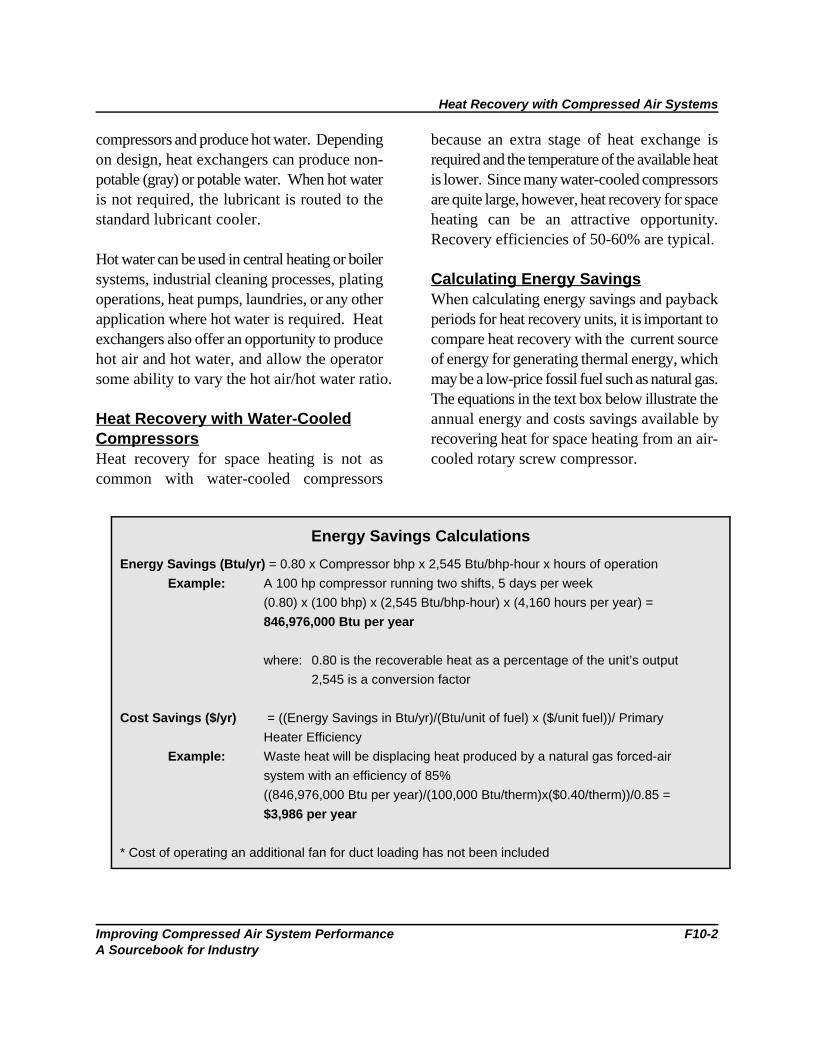
Energy Savings Calculations
Energy Savings (Btu/yr) = 0.80 x Compressor bhp x 2,545 Btu/bhp-hour x hours of operation
Example: A 100 hp compressor running two shifts, 5 days per week
(0.80) x (100 bhp) x (2,545 Btu/bhp-hour) x (4,160 hours per year) =
846,976,000 Btu per year
where: 0.80 is the recoverable heat as a percentage of the unit’s output
2,545 is a conversion factor
Cost Savings ($/yr) = ((Energy Savings in Btu/yr)/(Btu/unit of fuel) x ($/unit fuel))/ Primary
Heater Efficiency
Example: Waste heat will be displacing heat produced by a natural gas forced-air
system with an efficiency of 85%
((846,976,000 Btu per year)/(100,000 Btu/therm)x($0.40/therm))/0.85 =
$3,986 per year
* Cost of operating an additional fan for duct loading has not been included
compressors and produce hot water. Depending because an extra stage of heat exchange ison design, heat exchangers can produce non- required and the temperature of the available heatpotable (gray) or potable water. When hot water is lower. Since many water-cooled compressorsis not required, the lubricant is routed to the are quite large, however, heat recovery for spacestandard lubricant cooler. heating can be an attractive opportunity.
Hot water can be used in central heating or boilersystems, industrial cleaning processes, plating Calculating Energy Savingsoperations, heat pumps, laundries, or any other When calculating energy savings and paybackapplication where hot water is required. Heat periods for heat recovery units, it is important toexchangers also offer an opportunity to produce compare heat recovery with the current sourcehot air and hot water, and allow the operator of energy for generating thermal energy, whichsome ability to vary the hot air/hot water ratio. may be a low-price fossil fuel such as natural gas.
Heat Recovery with Water-Cooled annual energy and costs savings available byCompressors recovering heat for space heating from an air-Heat recovery for space heating is not as cooled rotary screw compressor.common with water-cooled compressors
Recovery efficiencies of 50-60% are typical.
The equations in the text box below illustrate the
Improving Compressed Air System Performance F11-1A Sourcebook for Industry
Proven Opportunities at the Component Level
Compressed Air Systems Fact Sheet #11
In some cases, taking a systems approach to Reciprocating Compressors. In the past,analyzing compressed air systems can facilitate reciprocating air compressors were the mostthe analysis of an individual component as well as widely used compressors in industrial plant airperformance issues relating to individual system systems. Single-acting reciprocating compressorscomponents. In general, compressed air systems are generally air-cooled, in the smaller hp sizes,contain five major subsystems: (1) compressors; and do not require substantial foundations.(2) prime mover; (3) controls; (4) air treatment However, these compressors are less efficientequipment and other accessories; and (5) the air than other types. Double-acting reciprocating airdistribution subsystem. Performance aspects of compressors are generally water-cooled andeach of these subsystems are discussed in detail require substantial foundations. Multi-stagebelow. versions are usually considered to be the most
Compressors installation costs and higher maintenanceWhile there are many different types of requirements.compressors, all compressor types theoreticallyoperate more efficiently if they are designed to Rotary Positive-Displacementinclude multiple stages. With multiple stages, thefinal discharge pressure is generated over severalsteps, thereby saving energy. Many multi-stagecompressors save energy by cooling the airbetween stages, reducing the volume and workrequired to compress the air. In spite of this,many industrial compressors only have a singlestage because equipment manufacturing costs arelower. Performance and efficiency issues of thethree most common types of compressors --single- and double-acting reciprocatingcompressors, rotary positive-displacementcompressors, and centrifugal compressors -- arediscussed below.
Single- and Double-Acting
efficient air compressors but have high initial and
Compressors. Today, lubricant-injectedrotary screw compressors are used in mostindustrial plant air applications and for largeapplications in the service industries. They havesome advantages over reciprocatingcompressors, including lower initial installationand maintenance costs; smaller size; reducedvibration and noise; reduced floor spacerequirements; and the ability to be installed on alevel industrial plant floor. Rotary screwcompressors provide continuous flow and do nothave the type of pressure pulsations typicallyassociated with reciprocating compressors.Two-stage rotary-screw compressors are moreefficient than single-stage units. Lubricant-injected rotary screw compressors are typicallyless efficient than two-stage double-acting
Proven Opportunities at the Component Level
Improving Compressed Air System Performance F11-2A Sourcebook for Industry
reciprocating compressors or three-stage Lubricant-free compressors may be appropriatecentrifugal compressors. In general, rotary screw for specific applications or to meet specificcompressors are also less efficient at part-load environmental regulations. Lubricant-free rotarythan reciprocating compressors. screw and reciprocating compressors are
A wide range of models is usually available from machines.different manufacturers for any given application.Users should try to select the most efficient model Prime Moversavailable (see the Fact Sheet titled Packaged The majority of industrial compressed air systemsCompressor Efficiency Ratings). use electric motors as the prime mover.
Centrifugal Compressors. The use of motors are used in 90% of all industrialcentrifugal compressors is usually limited to high- compressor applications due to their reliability,volume industrial plant applications, such as level of efficiency (85-95%, depending on size),chemical manufacturing, textile plants, petroleum and excellent starting torque, and despite theirrefining, or general plant air systems in large high inrush current requirements. Inrush currentmanufacturing facilities. The compressors is the amount of current that is required to startoperate at high speeds and therefore use smaller, the motor and motor-driven equipment. Mostmore compact equipment. Three-stage major manufacturers of industrial packagedcentrifugal compressors are generally more compressed air systems now offer both standardefficient than rotary screw compressors and can and energy-efficient motors. As of October 24,approach the efficiency levels of double-acting 1997, standard three-phase induction motorsreciprocating compressors. Centrifugal air between 1 and 200 hp are required to meetcompressors are available for 100 psig discharge minimum federal efficiency levels. This meanspressure from 100-hp, but most are 300-hp or that all general-purpose motors are at thelarger, with an increasing number of stages and efficiency levels of those formerly labeled “highimproving efficiency as size increases. efficiency” or “energy-efficient.” Even with theseCentrifugal compressors are best suited to new minimum efficiency levels, there is a range ofapplications where demand is relatively constant efficiencies available for any given application,or in industrial plants where they can be used and manufacturers will likely offer lines ofprimarily for base-load operation, allowing other premium-efficiency motors that have highercompressor types to be as used as trim machines efficiencies than standard-efficiency motors.to meet peak demands.
Lubricant-Free Compressors. Lubricant- v-belt, or direct coupled. Proper alignment isfree versions of reciprocating and rotary air critical for all applications. Direct coupling resultscompressors are available. Centrifugal air in the least loss of efficiency, while v-beltcompressors are inherently lubricant-free. applications may allow for more compact
generally less efficient than lubricant-injected
Standard, three-phase squirrel-cage induction
Motors can be flange mounted, connected with a
Proven Opportunities at the Component Level
Improving Compressed Air System Performance F11-3A Sourcebook for Industry
packaging. V-belts should always be inspected quality requirements. For optimum performance,and tensioned per manufacturer’s specification to air treatment equipment should be operated asavoid increased power transmission losses. close to manufacturers’ design conditions as
Due to the heavy duty and load cycles on most system accessory equipment and performancecompressors, it almost always makes sense to follows.buy the most efficient motor available. Theincremental cost for a more efficient motor is Dryers. Compressed air system performancetypically paid back in less than one year from the is typically enhanced by the use of dryers, butresulting energy savings. Users should be aware since they require added capital and operatingthat new energy-efficient motors sometimes have costs (including energy), drying should only belower available starting torque than standard performed to the degree that it is needed for themotors and often have slightly higher operating proper functioning of the equipment and the end-speeds because of reduced slip. Match use.operating speeds as closely as possible whenreplacing a motor. Single tower chemical deliquescent dryers use
Controls suppression of 15 to 50EF below the dryer inletCompressor control mechanisms are used to temperature, depending on the desiccantmatch the compressed air volume and pressure selected. They are not suitable for some systemsdelivered by the compressor with facility demand. that have high drying needs. Compressor controls are often the most important factor determining a Refrigerant-type dryers are the most commoncompressor’s ability to perform at part-load and provide a pressure dewpoint of 35 to 39EF,efficiently. Controls are frequently configured which is acceptable for many applications. Inpoorly, and proper control strategies can lead to addition to the pressure drop across the dryersubstantial reductions in energy consumption. (usually 3-5 psid), the energy to run the
For more information on controls and Some refrigerant-type dryers have the ability tocompressed air system performance, see the Fact cycle on and off based on air flow, which maySheet titled Compressed Air System Controls. save energy.
Air Treatment Equipment and Other Twin tower desiccant-type dryers are the mostAccessories effective in the removal of moisture from the airAir treatment equipment must provide for both and typically are rated at a pressure dewpoint ofcontaminant removal and preparation of the air -40EF. The purge air requirement can rangefor equipment use. The level of air conditioning from 10 to 18% of the total air flow, dependingand accessories needed is often dependent on air on the type of dryer. This energy loss, in addition
possible. A discussion of important compressor
little energy, but provide pressure dewpoint
refrigerant compressor must be considered.
Proven Opportunities at the Component Level
Improving Compressed Air System Performance F11-4A Sourcebook for Industry
to the pressure drop across the dryer, must be as indicated by pressure differential, and at leastconsidered. The heated-type requires less purge annually, to minimize pressure drop and energyair for regeneration, as heaters are used to heat consumption. the desiccant bed or the purge air. The heaterenergy must also be considered against the Air Receiver. Air receivers are designed toreduction in the amount of purge air, in addition provide a supply buffer to meet short-termto the pressure drop. Heat-of-compression demand spikes which can exceed the compressordryers may be used where the lubricant-free capacity. They also serve to dampencompressor discharge temperature is sufficiently compressor pulsations, separate out particles andhigh to achieve regeneration of the desiccant. liquids, and make the compressed air systemThere is no reduction of air capacity with this easier to control. Installing a larger receiver tanktype of dryer since hot, unsaturated air from the to meet occasional peak demands can even allowcompressor discharge is used for regeneration, for the use of a smaller compressor.then cooled and some of the moisture isremoved as condensate before passing through In most systems, the receiver will be located justthe drying section. Vacuum-assisted regeneration after the dryer. In some cases, it makes sense tois typically the most efficient, with unheated purge use multiple receivers, one prior to the dryer andair flow the least efficient. one closer to points of intermittent use.
Compressed Air Filters. These include Storage can be used to control demand eventsparticulate filters to remove solid particles, (peak demand periods) in the system bycoalescing filters to remove lubricant and controlling both the amount of pressure drop andmoisture, and adsorbent filters for very fine the rate of decay. Storage can be used tocontaminants. A particulate filter is recommended protect critical pressure applications from otherafter a desiccant-type dryer to remove desiccant events in the system. Storage can also be used to“fines”. A coalescing-type filter is recommended control the rate of pressure drop in demand whilebefore a desiccant-type dryer to prevent fouling supporting the speed of transmission responseof the desiccant bed. Additional filtration may from supply. Many systems have a compressoralso be needed to meet requirements for specific operating in modulation to support demandend-uses. events, and sometimes, strategic storage solutions
Compressed air filters downstream of the air Storage can also help systems ride through acompressor are generally required for the compressor failure or short energy outages.removal of contaminants, such as particulates,condensate, and lubricant. Filtration only to the Condensate/Lubricant Separators. It islevel required by each compressed air application no longer acceptable to discharge condensatewill minimize pressure drop and resultant energy from a compressed air system to sewer linesconsumption. Elements should also be replaced without treatment to remove contaminants such
can allow for this compressor to be turned off.
Proven Opportunities at the Component Level
Improving Compressed Air System Performance F11-5A Sourcebook for Industry
as entrained lubricants (except for condensate The air distribution subsystem, which connectsfrom some lubricant-free compressor systems). the major components, is one of the mostCondensate/lubricant separators are available in important parts of the compressed air system. Itthe marketplace to achieve separation by means is made up of main trunk lines, hoses and valves,of settling tanks and/or permeable membranes. drops to specific usage points, pressureThis equipment helps to avoid the potentially high regulators and lubricators, additional filters andcosts of contaminated waste disposal, although traps, and supplementary air treatmentsome lubricants are water soluble and equipment. It is throughout this subsystem thatbiodegradable and can be disposed of in the most leaks occur, energy is lost, and maintenancesewer system (check local regulations). required. Equipment should be chosen to avoid
Air/Lubricant Separators. The air/lubricant addition, consideration of appropriate sizing ofseparator in a lubricant-cooled rotary screw equipment and layout will provide for proper aircompressor generally starts with a 2-3 psid supply, good tool performance, and optimalpressure drop at full-load when new. production. The complete drying, filtration, andMaintenance manuals usually suggest changing distribution system should be sized and arrangedthem when there is a 10-12 psid pressure drop so that the total pressure drop from the airacross the separator. In many cases it may make compressor to the points of use is much less thansense to make an earlier separator replacement, 10% of the compressor discharge pressure.especially if electricity prices are high.
Heat Recovery Systems. Most systems do partially open at all times to allow for constantnot employ heat recovery, even though draining. This practice wastes substantial energyeconomics can be good, with typical paybacks of and should never be undertaken. If a float-less than one year. Heat recovery systems operated automatic condensate drain is notrequire electricity for fans or pumps, but can functioning properly, clean and repair it instead ofdecrease the need for fossil fuels usually used for leaving it open. If maintenance of float-operatedheating. See the Fact Sheet titled Heat drain traps is a burden, consider replacing themRecovery with Compressed Air Systems for with more reliable demand-type drain traps.more information on this energy savingopportunity. The efficiency of the entire system can be
The Air Distribution Subsystem. installation, and maintenance of each component.
excessive pressure drops and leakage. In
Some users leave automatic condensate traps
enhanced by the proper selection, application,