cabling installation and maintenance - jan 2009 (malestrom)
DESCRIPTION
Fiber Optic MagazineTRANSCRIPT
www.cablinginstall.com
Solutions for Premises and Campus Communication Systems Worldwide January 2009
Smart infrastructures for video
Essentials of an 802.11y network
Power plus data in one conduit
OM4 WINS THE RACE
Contents Zoom In Zoom Out Search Issue Next PageFor navigation instructions please click here
Contents Zoom In Zoom Out Search Issue Next PageFor navigation instructions please click here
How can Corning Cable Systemssimplify your local area network(LAN) connectivity?
© 2008 Corning Cable Systems LLC
Connecting toys are classic: simple yet multifunctional. Each piece is
pre-engineered to integrate precisely with one another, making use
fast and easy.
Corning Cable Systems Plug & Play™ AnyLAN™ Systems deploy with that
same “connect the dots” ease. YOU control where network connectivity occurs, how
quickly it happens and how successfully it is deployed. Network access is built directly
into the cabling – simply pull the cable and connect with preterminated drop cable
assemblies that attach as easily as connecting a garden
hose. No midspan cable access, no splicing, no worries.
At Corning Cable Systems, innovation is timeless.
Please visit www.corning.com/zeux for more information
on LANscape® Solutions for your local area network and to
receive a free gift!
EASE OF
INSTALLATION.
| | | | | |Previous Page Contents Zoom in Zoom out Refer a Friend Search Issue Next Page BA
M SaGEFC7Installation MaintenanceC7
| | | | | |Previous Page Contents Zoom in Zoom out Refer a Friend Search Issue Next Page BA
M SaGEFC7Installation MaintenanceC7

CPI Passive Cooling® Solutions are simply the mostefficient choice for today’s data centers. From smallapplications with heat loads of 2 kW to large datacenters with high heat densities beyond 20+ kW . . .CPI’s proven solutions can work for you.
Learn more about CPI Passive Cooling Solutions bygoing to our Website:www.chatsworth.com/passivecooling.
Simply
www.chatsworth.com or [email protected] 800-834-4969
• Maximize cooling unit efficiency
• Reduce data center operating costs
• Minimize environmental impact
CP
I Passive Coolin
gT
MT
M
Simply Efficie
ntTM
Efficient
Organize.Store.Secure.SM
| | | | | |Previous Page Contents Zoom in Zoom out Refer a Friend Search Issue Next Page BA
M SaGEFC7Installation MaintenanceC7
| | | | | |Previous Page Contents Zoom in Zoom out Refer a Friend Search Issue Next Page BA
M SaGEFC7Installation MaintenanceC7

| | | | | |Previous Page Contents Zoom in Zoom out Refer a Friend Search Issue Next Page BA
M SaGEFC7Installation MaintenanceC7
| | | | | |Previous Page Contents Zoom in Zoom out Refer a Friend Search Issue Next Page BA
M SaGEFC7Installation MaintenanceC7
_________
departments
CABLING INSTALLATION & MAINTENANCE © 2009 (ISSN 1073-3108), is published 12 times a year, monthly, by PennWell Corporation, 1421 South Sheridan Road, Tulsa, OK 74112; telephone (918) 835-3161; fax (918) 831-9497; Web address www.pennwell.com. Periodicals postage paid at Tulsa, OK 74101 and other additional offi ces. Subscriptions rate in the USA: 1 yr. $88, 2 yr. $119, BG $132; Canada/Mexico: 1 yr. $98, 2 yr. $132, BG $138; International via air: 1 yr. $120, 2 yr. $160, BG $144; Digital: 1 yr. $60. If available, back issues can be purchased for $17 in the U.S. and $22 elsewhere. Editorial offi ces: 98 Spit Brook Road, Nashua, NH 03062-5737; telephone (603) 891-0123. All rights reserved. Authorization to photocopy items for internal or personal use, or the internal or personal use of specifi c clients, is granted by CABLING INSTALLATION & MAINTENANCE (ISSN 1073-3108), provided that the appropriate fee is paid directly to Copyright Clearance Center, 222 Rosewood Drive, Danvers, MA 01923 USA; (978) 750-8400. Prior to photocopying items for educational classroom use, please contact Copyright Clearance Center, Inc., 222 Rosewood Drive, Danvers, MA 01923 USA; (978) 750-8400. For further information, check CCC Online at the following address: http://www.copyright.com/. All rights reserved. No material may be reprinted. Bulk reprints can be ordered from Diane Troyer, telephone (603) 891-9135. Corporate offi cers: Frank T. Lauinger, Chairman; Robert F. Biolchini, President and CEO; Mark Wilmoth, Chief Financial Offi cer.
We make portions of our subscriber list available to carefully screened companies that offer products and services that may be important for your work. If you do not want to receive those offers and/or information, please let us know by contacting us at List Services, CABLING INSTALLATION & MAINTENANCE, 98 Spit Brook Road, Nashua, NH 03062-5737.
POSTMASTER: Send address changes to: Cabling Installation & Maintenance, P.O. Box 3280, Northbrook, IL 60065-3280. Return undeliverable Canadian addresses to: P.O. Box 122, Niagara Falls, ON, Canada L2E 6S4. PRINTED IN THE USA. GST No. 126813153 Publications Mail Agreement no. 1421727
features
CO
VE
R C
ON
CE
PT B
Y D
AN
RO
DD
www.cablinginstall.com Cabling Installation & Maintenance ■ January 2009 ■ 3
JANUARY 2009 VOL. 17, NO. 1
7 Using your infrastructure to support video applicationsSmart applications require smart infrastructure. Is yours up to the
task? VALERIE MAGUIRE
17 Increased effi ciency with unifi ed communicationsA Voice over Internet Protocol system anchors the unifi ed-
communications project taking place at Cooper Industries. PATRICK
MCLAUGHLIN
23 Multimode fi bers rise to the challenge An update on the current state of optical fi ber in standards, including
the defi nition of OM4. FIBER OPTICS LAN SECTION (FOLS)
27 Essentials of an 802.11y networkThe recently approved standard will allow for high-powered Wi-Fi-
enabled communications at distances of 3 miles or more.
STEVE SMITH
31 INDUSTRY SPOTLIGHT
■ Barrier cable technology allows for power, low-voltage in
one conduit
■ Survey: wireless is hottest thing on campus
■ High-speed networking alliances plan to merge
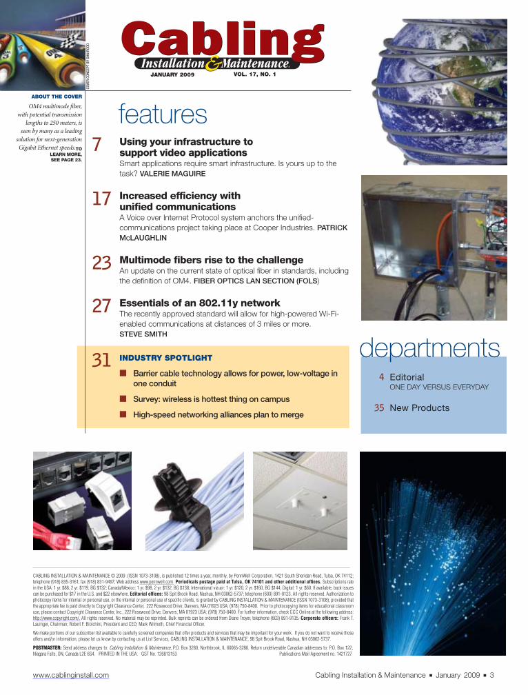
ABOUT THE COVER
OM4 multimode fi ber,
with potential transmission
lengths to 250 meters, is
seen by many as a leading
solution for next-generation
Gigabit Ethernet speeds.TO
LEARN MORE,
SEE PAGE 23.
4 Editorial
ONE DAY VERSUS EVERYDAY
35 New Products
| | | | | |Previous Page Contents Zoom in Zoom out Refer a Friend Search Issue Next Page BA
M SaGEFC7Installation MaintenanceC7
| | | | | |Previous Page Contents Zoom in Zoom out Refer a Friend Search Issue Next Page BA
M SaGEFC7Installation MaintenanceC7
______________

PATRICK McLAUGHLIN
Chief Editor
4 ■ January 2009 ■ Cabling Installation & Maintenance www.cablinginstall.com
Publisher / Tim Pritchard
(603) 891-9447 • [email protected]
Chief Editor / Patrick McLaughlin
(603) 891-9222 • [email protected]
Executive Editor / Steve Smith
(603) 891-9139 • [email protected]
Senior Editor / Matt Vincent
(603) 891-9262 • [email protected]
Circulation Manager / Michelle Blake
(603) 891-9360 • [email protected]
Art Director / Kelli Mylchreest
Lead Illustrator / Dan Rodd
Senior Vice President/Group Publishing Director
Christine Shaw
(603) 891-9178 • [email protected]
Associate Publisher/National Sales Manager
Ed Murphy
(603) 891-9260 • [email protected]
CABLING INSTALLATION & MAINTENANCE EXECUTIVE AND EDITORIAL OFFICES
PennWell Technology Group
98 Spit Brook Road
Nashua, NH 03062-5737
Tel: (603) 891-0123, fax: (603) 891-9245
Internet: www.cablinginstall.com
SUBSCRIPTION INQUIRIES:
For subscriptions or to change your format to print
or digital, please go to: www.cim-subscribe.com.
Subscriptions outside the USA are available in digital
format only.
CORPORATE OFFICERS
Chairman / Frank T. Lauinger
President and Chief Executive Offi cer
Robert F. Biolchini
Chief Financial Offi cer / Mark C. Wilmoth
TECHNOLOGY GROUP
VP Audience Development / Gloria S. Adams
TECHNOLOGY GROUP PUBLISHING SERVICES DEPARTMENTS
Art Director / Meg Fuschetti
Production Director / Mari Rodriguez
(603) 891-9193 • [email protected]
Marketing Communication Manager
Kristen Jones
(603) 891-9425 • [email protected]
Ad Traffi c Manager / Bettie Gaines
(918) 832-9369 • [email protected]
PRINTED IN THE USA GST NO. 126813153
Publications Mail Agreement Number 40052420
One day versus everyday
One summer, I worked as an
attendant at a convenience-
store/gas-station chain. My
duties were pumping gas and ensur-
ing some parts of the convenience
store remained stocked. As a low-lev-
el employee, I had a seemingly endless
list of superiors. I
had a supervi-
sor who was the
head gas-pump-
er/shelf-stocker.
He answered to
the store manager.
The store man-
ager answered to
a regional manager who answered
to a district manager. Or maybe the
district manager answered to the
regional manager. I can’t remember.
Anyway, one day the regional
manager (or maybe it was the dis-
trict manager) was supposed to pay
a visit to the store. You should have
seen how the place operated that day;
we went through more Windex and
Spic’n’Span in one shift than we did
the rest of the summer. Everything
had to be in the best possible shape
because apparently the store was go-
ing to receive a grade from the region-
al/district manager.
Unfortunately, I can’t tell you the
rest of the story because I wasn’t
there when the person handing out
the grades showed up. All I can say is
that the store’s staff remained intact
throughout the summer, so we must
have done OK.
What became evident even to a
naïve kid like me was the grade we
got that day did not represent every-
day reality. It represented our abso-
lute best eff ort for a very short period
of time. Unfortunately, that’s exactly
the phenomenon some of you might
be experiencing as users of structured
cabling systems.
A recent report from the Commu-
nications Cable and Connectivity
Association said that cables purchased
off distributor shelves failed to meet
the electrical- and fl ame-resistance
performance they claimed on their
outer jackets. Th e CCCA has been
quick to point out the brands are not
prominent in North America, and
each of the cables was made by an
off shore manufacturer.
But the deeper question is: Did
these cables ever really pass CMP/
CMR and electrical-performance
tests, and receive third-party lab rec-
ognition of that performance? If so,
then on the day these manufacturers
produced the cable to be tested, they
acted as if the district manager was
paying a visit. Everything from ma-
terials to processes was buttoned up
tightly for one day. Th en they went
back to their normal routine of far-
less-strict practices. On the other
hand, if they never went through
such testing, then these manufactur-
ers are fraudulently portraying that
they did.
We’re tracking this story now and
will have more details next month, as
well as on www.cablinginstall.com.
| | | | | |Previous Page Contents Zoom in Zoom out Refer a Friend Search Issue Next Page BA
M SaGEFC7Installation MaintenanceC7
| | | | | |Previous Page Contents Zoom in Zoom out Refer a Friend Search Issue Next Page BA
M SaGEFC7Installation MaintenanceC7
CONNECTING THE WORLD TO A HIGHER STANDARD
W W W . S I E M O N . C O M
Z-MAX is not merely a collection of components, but an optimized end-to-end category6A UTP and Shielded system developed from the ground up shattering the limitationsof the RJ45 as we know it today.
Siemon Labs has again proven its technology leadership with breakthrough Z-MAXinnovations including zero-cross termination and PCB-based patchcords (patent pending)that enable best-in-class performance across every critical category 6A parameter.
But Z-MAX performance did not come at the expense of simplicity and usability.In fact, the groundbreaking Z-MAX termination process is by far the fastest category6A termination in the world - 60 seconds for both UTP and Shielded.
And this is only the first rumblings of the storm. To learn about other Z-MAX innovations,such as the system’s high-density 48 port, 1U patch panels and flexible flat/angled hybridmodules, or to see video of the Z-Tool termination process, visit www.siemon.com
Z-MAX™
Introducing Z-MAX, The Siemon Structured Cabling Revolution
The Storm has Arrived!
| | | | | |Previous Page Contents Zoom in Zoom out Refer a Friend Search Issue Next Page BA
M SaGEFC7Installation MaintenanceC7
| | | | | |Previous Page Contents Zoom in Zoom out Refer a Friend Search Issue Next Page BA
M SaGEFC7Installation MaintenanceC7
_____________________

YOU’RE SO PREDICTABLEWhy…Thank you!
The conditions in which premises optical fiber cables are installed can’t always be predicted.
That’s why it’s important to install an optical fiber cable from the company that’s always, well, predictable.
Superior Essex manufactures quality, high performance premises optical fiber cables for every installation, for every run - every time. And, we’ve established a long-standing reputation with leading corporations and institutions for providing on-time delivery and expert technical support.
So when you say Superior Essex is predictable, we consider it a compliment.
View our broad portfolio of premises fiber cables and installations at: www.spsx.com/comm/predictable.aspx
Y O U R C O M M U N I C AT I O N S E X P E R T S
| | | | | |Previous Page Contents Zoom in Zoom out Refer a Friend Search Issue Next Page BA
M SaGEFC7Installation MaintenanceC7
| | | | | |Previous Page Contents Zoom in Zoom out Refer a Friend Search Issue Next Page BA
M SaGEFC7Installation MaintenanceC7
______________

Camera
Balun
Telecommunications
outlet
Interconnect panel
(optional)
Televison
Televison
DVRVideo distribution hub (balun)
Power cordPatch cord
Horizontal
cable
Fixed or PTZ camera
Interconnect panel
(optional)
Horizontal
cable
PVD video
integrator
Class II
power
supply
(24 VAC)
PVD video transceiver
Power
Source: Siemon
Twisted-pair
cabling
PVD video receiver
PVD Camera (No PTZ)
Data
DVR
Wiring ClosetControl Room
Camera
Typical analog CCTV surveillance topologies
www.cablinginstall.com design
www.cablinginstall.com Cabling Installation & Maintenance ■ January 2009 ■ 7
Today’s surveillance and broad-
band video applications are down-
right smart. Consider the following:
• Surveillance equipment boasting Internet
Protocol (IP)-addressable interfaces and
remote-control features off er signifi cant-
ly more security and fl exibility than fi xed
analog devices;
• IP-based systems record images in digital
format onto servers or hard drives, render-
ing the use of cumbersome tapes and cas-
settes for video storage obsolete;
• Community antenna television (CATV)
will migrate to virtually interference-free,
100% digital broadcasting in February;
• Emerging Internet Protocol Television (IP-
TV) technology promises on-demand, inter-
active, high-defi nition viewing experience.
Th ese applications are no longer suitably
supported by generic coaxial cabling; they
require smart cabling, too.
Growing smarter
Th e number of design professionals and
building owners choosing to support sur-
veillance, broadcast, and other video ap-
plications with their telecommunications
cabling infrastructure is climbing rapid-
ly. For example, according to a report from
Multimedia Intelligence (www.multimedi-
aintelligence.com) entitled “Internet Proto-
col/Networked Video Surveillance Market:
Equipment, Technology, and Semiconductors,” the mar-
ket for IP/networked video surveillance cameras grew
nearly 50% in 2007 to approach $500 million worldwide.
Th e market segment is growing at more than four times
the rate of the overall surveillance market.
In addition to replacing coaxial cables with slimmer
and more-fl exible balanced twisted-pair cables, the ben-
efi ts provided by using a structured telecommunica-
tions cabling network to support video applications are
numerous, including:
• Digital image quality;
In a typical analog CCTV surveillance-system topology, the video-distribution
hub or PVD integrator is located in the TR, and the system has a coaxial back-
bone. The interconnect patch panel is recommended for system fl exibility.
➤
Using your infrastructure tosupport video applications
Smart applications require smart
infrastructure. Is yours up to the task?
VALERIE MAGUIRE is global sales engineer with Siemon (www.siemon.
com).
| | | | | |Previous Page Contents Zoom in Zoom out Refer a Friend Search Issue Next Page BA
M SaGEFC7Installation MaintenanceC7
| | | | | |Previous Page Contents Zoom in Zoom out Refer a Friend Search Issue Next Page BA
M SaGEFC7Installation MaintenanceC7
__
____________
____________

Telecommunications outlet
Wireless access
point coverage area
Source: Siemon
Wall
Ceiling coverage areas
TO
TO
TO
TO
TO
TO
TO
TO
TO
TO
TO
TO
TO
rs
12m
8 ■ January 2009 ■ Cabling Installation & Maintenance www.cablinginstall.com
• Ability to support high-defi nition (480i/p SDTV and 720p
and 1080 i/p HDTV) applications;
• Active surveillance area motion, audio, and
tamper detection with advanced security alerts;
• Pan/tilt/zoom and remote-powered devices, eliminating the
need for separate power and control cables;
• End-user ability to communicate and interact with “smart”
video devices;
• Compact and highly efficient storage and retrieval
capabilities;
• Convergence of voice, data, and video applications over a
single common infrastructure;
• Full support of standards-based cabling distances and
topologies;
• More-eff ective infrastructure management, service, and
scalability;
• Simplifi ed troubleshooting;
• Improved asset management via IP-addressability;
• Neater pathways and improved pathway fi ll-ratios;
• Ability to upgrade to future applications;
• Lower total cost of ownership for many IP-based versus
analog-camera implementations.
Planning for video
If you are not sure you need to support video now, the rec-
ommendation is to include in your cabling plans additional
twisted-pair channels specifi cally targeted for video applica-
tions to accommodate future system needs. While you may
not currently anticipate the need to support surveillance
applications with your infrastructure, you cannot ignore that,
with increasing safety and security requirements worldwide,
the surveillance industry is growing rapidly. According to the
RNCOS Industry Research Solutions study, “Global CCTV
Market Analysis” (www.rncos.com), the global CCTV mar-
ket—including analog and IP-based CCTV—grew at a com-
pound annual growth rate (CAGR) of 24.28% in 2007 over
2006. Th e same study forecasts the market to grow at a CAGR
of approximately 23% between 2008 and 2012.
Planning now for video-applications support makes good
business sense as well. According to a total cost of ownership
analysis recently published by Axis Communications (www.
axis.com), IP-based video systems always have lower imple-
mentation costs than analog-based systems if the cabling
infrastructure is already present.
All surveillance and broadband video applications,
Identifying the exact location of surveillance cameras at any
time during the cabling design phase, as well as develop-
ing a fl exible surveillance infrastructure that can accommo-
date device moves and upgrades, can be challenging. One
way to overcome this challenge is to piggyback surveillance
equipment access points with wireless access points.
This approach supports all surveillance topologies and
may be especially convenient for the management of
installations in which cable sharing is used to support up
to four 1-pair video signals over one Category 7/7A fully-
shielded channel.
TIA TSB-162 Telecommunications Cabling Guidelines
for Wireless Access Points and ISO/IEC 24704 Information
Technology—Premises Cabling for Wireless Access Points,
offers guidance on locating wireless access points in ceiling
spaces that can be applied to video-equipment access
points. A pattern of circles or grids with coverage areas is
defi ned, with the intention that work area outlets be cen-
trally located in their coverage area and MUTOAs centrally
located in their associated coverage area grid.
Although coverage areas may range in size from 3 to 30
meters, 12 meters is generally recommended as an opti-
mum size to accommodate most wireless and surveillance
applications.—VM
Juxtaposing surveillance equipment and wireless access-point coverage
This example of ceiling coverage areas for video equipment and/or
wireless access points is based on the TIA’s TSB-162 and the ISO/IEC
24704 specifi cations.
➤
| | | | | |Previous Page Contents Zoom in Zoom out Refer a Friend Search Issue Next Page BA
M SaGEFC7Installation MaintenanceC7
| | | | | |Previous Page Contents Zoom in Zoom out Refer a Friend Search Issue Next Page BA
M SaGEFC7Installation MaintenanceC7
____
______

| | | | | |Previous Page Contents Zoom in Zoom out Refer a Friend Search Issue Next Page BA
M SaGEFC7Installation MaintenanceC7
| | | | | |Previous Page Contents Zoom in Zoom out Refer a Friend Search Issue Next Page BA
M SaGEFC7Installation MaintenanceC7
__________________________

Bring a little green to the jobsite.Leviton’s new GreenPack™ is loaded with 24 RoHS-compliant connectors. And it’s recyclable. That means less pollution, fewer heavy metals in landfi lls, and a safer environment for everyone.
Clear, easy-open pockets allow you to pop out just one connector at a time, and instantly see how many you have left. In fact, GreenPacks are so quick and easy to use, you’ll have time to hug a tree.
Now GreenPacks are available at Leviton distributors, so visit your local branch today.Or call 800-922-6229 for more information. Available in fi ve colors in GigaMax® 5e/5e+ and eXtreme® 6+ connector styles.
BringLeviton’s newThat means l
Clear, easy-omany you ha
Now GreenPaOr call 800-9eXtreme® 6+
LEVITON.COM | P 800.922.6229 | F 425.483.5270ISO 9001:2000 registered quality manufacturer | © 2008 Leviton Manufacturing Co., Inc
| | | | | |Previous Page Contents Zoom in Zoom out Refer a Friend Search Issue Next Page BA
M SaGEFC7Installation MaintenanceC7
| | | | | |Previous Page Contents Zoom in Zoom out Refer a Friend Search Issue Next Page BA
M SaGEFC7Installation MaintenanceC7
________

TheApplications AssuranceTester
Validator-NT documents floor plans, certifies
Ethernet speeds with BER testing, ensures
IP configuration and connectivity, and verifies
cable continuity—exactly what you need to get
the job done at a price less than you expect.
Look for Validator-NT and the entire line of
network and enterprise test tools through our
worldwide distributor network.
Visitwww.jdsu.com/know to locate a distributor
near you.You’ll find JDSU quality, network testing
experience, and value built into every tool.
Know theNetwork
Validator-NT™ Ethernet Speed Certifier NT955
www.cablinginstall.com Cabling Installation & Maintenance ■ January 2009 ■ 11
when appropriate amplifi cation is used
to boost CATV signal levels at higher-
frequency channels, are capable of oper-
ating over lengths of twisted-pair cabling
greater than 100 meters. But maintaining
the TIA/EIA- and ISO/IEC-specifi ed ge-
neric maximum 100-meter, 4-connector
horizontal channel topology has numer-
ous benefi ts and is strongly recommended
for video-applications support. In par-
ticular, adhering to the generic topology
ensures that upgrades to future video ap-
plications will occur seamlessly, while
also providing the fl exibility that chan-
nels originally designed for high-speed
data support can be used for video if nec-
essary, and vice versa.
Pretty simple, actually
Video-deployment planning is sim-
ple: bring video-ready twisted-pair ca-
bling, in addition to data cabling, to each
work area or multi-user telecom-
munications outlet assembly
(MUTOA). For support of sur-
veillance applications in areas
where wireless coverage is pro-
vided, it may be convenient to
juxtapose video access points
with wireless access points in
the coverage area. (See sidebar,
“Juxtaposing surveillance-equip-
ment and wireless access-point
coverage.”) Th e advantage to this
approach is that the telecommu-
nications outlet is conveniently located
in the ceiling space where cameras re-
side, and video-equipment positioning
is more fl exible.
IP-enabled video devices are precon-
fi gured to accept the 8-position modular
plug interface and off er plug-and-play
capability with structured telecommuni-
cations cabling. Generic analog devices,
such as CCTV cameras, monitors, and
television sets, are typically confi gured
with coaxial BNC or Type F connectors
and require the use of video baluns to
enable transmission over twisted-pair
cabling.
Video baluns are used in pairs to con-
vert a 75-Ω unbalanced (i.e., coaxial) sig-
nal at the video-equipment interface to
a 100-Ω balanced (i.e., twisted-pair) sig-
nal and then back to a 75-Ω unbalanced
signal at the telecommunications room
(TR) or fl oor distributor (FD). Video bal-
uns are application-specifi c, such as for
CATV or CCTV, and may be confi gured
as single-port converters for use at the de-
vice interface, as single-port converters
located in breakout boxes for use at the
work area, or in 8- and 16-port video-dis-
tribution hubs for use in the TR. Video
baluns may also be integrated into high-
performance Category 7/7A patch cords.
CCTV surveillance applications
Video security can be an eff ective de-
fense in detecting threats as well as a
deterrent against future threats. CCTV
solutions are simple to deploy; consist-
ing of fi xed or remote-controlled cam-
eras, cabling, a recoding device, and a
monitoring device. While mandatory for
highly secure environments, such as gov-
ernment buildings, prisons, and casinos,
surveillance systems are now also com-
monplace in education, healthcare, indus-
trial, and fi nancial facilities.
This one-pair Category 7/7A TERA-to-Type F cord inte-
grates a balun.
The BNC (l) and Type F are common analog-
video connector interfaces.
| | | | | |Previous Page Contents Zoom in Zoom out Refer a Friend Search Issue Next Page BA
M SaGEFC7Installation MaintenanceC7
| | | | | |Previous Page Contents Zoom in Zoom out Refer a Friend Search Issue Next Page BA
M SaGEFC7Installation MaintenanceC7
________________

Stewart Connector
PLUGS-CAT 3 to 7a
www.stewartconnector.com • 717/235-7512
Premise WiringCAT 6 • CAT 6a • CAT 7aModular Plugs & Jacks
•For Solid & Stranded Cable•Shielded and Unshielded
• Polished Contacts for High
•Multiple Keying and Wire Insertion Life
Management Options
JACKS-CAT 3 to 7a
•Horizontal, Vertical, and Angled•Shielded and Unshielded
• Single and Multi-Port Designs•PCB and Cable Mounted Designs
Mounting Options
Stewart Connector understands that specifying and sourcing quality modular connectors for premise and campuswide communications systems can be a tough job. Especially as technology, standards, and products continue to evolve. That is why we’ve engineered our plugs and jacks to ensure your networks’ superior performance... today and tomorrow.
12 ■ January 2009 ■ Cabling Installation & Maintenance www.cablinginstall.com
Historically, CCTV systems were stat-
ic and deployed as analog systems sup-
ported by coaxial cabling. Enhancements,
such as the availability of cost-eff ective
baluns and IP-addressable devices, now
make surveillance solutions the perfect ap-
plication for operation over twisted-pair
cabling. IP-based surveillance systems have
the added advantage that they are signifi -
cantly more fl exible and “intelligent” than
traditional analog CCTV systems. A wide
range of structured cabling solutions sup-
ports video surveillance applications.
Th e simplest analog video CCTV con-
fi guration is a static system consisting of a
fi xed camera, twisted-pair cable, a pair of
video baluns, and a recording device such
as a digital video recorder (DVR). Th e
video baluns are BNC/RJ-45 connectorized
devices that transmit black-and-white or
color images over one pair (the pair ter-
minated on pins 7-8) of the twisted-pair
cable. Optional PTZ capability supports
the remote-controlled operation of the
camera and off ers more fl exibility than
fi xed camera systems.
PTZ in focus
Adjusting the focus, angle, and fi eld of view
without being present at the camera site
are all benefi ts of a PTZ-enabled system.
Structured cabling that includes PTZ-en-
abled baluns, which use only the 7-8 pair to
transmit video and PTZ commands, easily
supports this functionality. Because these
solutions operate over only one pair of a
4-pair cable, they represent an excellent
opportunity to take advantage of the
cable sharing capability of Category
7/7A fully-shielded solutions. (For
more information on cable sharing, see
Adjusting the focus, angle,
and fi eld of view without
being present at the
camera site are all benefi ts
of a PTZ-enabled system.
| | | | | |Previous Page Contents Zoom in Zoom out Refer a Friend Search Issue Next Page BA
M SaGEFC7Installation MaintenanceC7
| | | | | |Previous Page Contents Zoom in Zoom out Refer a Friend Search Issue Next Page BA
M SaGEFC7Installation MaintenanceC7

OneTool for IP Device Installation
LanScaperPRO tests cables, verifies port
configuration,measures PoE power, and ensures
IP configuration and connectivity—exactly
what you need to get the job done at a price less
than you expect.
Look for LanScaperPRO and the entire line
of network and enterprise test tools through
our worldwide distributor network.
Visitwww.jdsu.com/know to locate a distributor
near you.You’ll find JDSU quality, network testing
experience, and value built into every tool.
Know theNetwork
LanScaperPRO™ Cable and Network Tester NT800
Source: SiemonVideo server
PoE switch
Interconnect panel
(Optional)
Patch panel
Camera recording,
playback and optional
controller software
Telecommunications
outlet or MuTOA
Horizontal cable
Camera
Typical IP-addressable CCTV surveillance topology
www.cablinginstall.com Cabling Installation & Maintenance ■ January 2009 ■ 13
www.cablinginstall.com: “In commer-
cial buildings, cable sharing makes
cents,” June 2006; that article is based
on the white paper, “Cable Sharing in
Commercial Building Environments:
Reducing Cost, Simplifying Cable Man-
agement and Converging Applications
Onto Twisted-pair Media.”)
Note that power must be provided
locally to each camera in both tradi-
tional coaxial and balun-based twist-
ed-pair CCTV camera deployments.
Depending upon the camera location,
providing separate power can range
from inconvenient to practically impos-
sible, and this need cannot be avoided in
coaxial implementations. Emerging PVD
(power-video-data) technology uses a
pair of powered video transceivers to ful-
ly support CCTV applications and elimi-
nate the need for external power cords by
transmitting video (one pair), power (two
pairs), and data (one pair) over one 4-pair
telecommunications cable.
PVD devices are not IP-enabled and
data is still collected on a traditional
external recording device, such as a DVR.
At this time, PVD transceiver solutions
easily accommodate the operation of
fi xed position cameras, which typically
consume less than 300 mA of power,
over 100-meter structured cabling
topologies. Be advised that the maxi-
mum distance supported by PTZ cam-
eras, which typically consume at least
600mA of power, is manufacturer-
dependent and may be less than 100
meters, causing these implementa-
tions to fall outside the scope of struc-
tured cabling. Th e good news is that
power delivery technology “borrowed”
from the emerging related IEEE 802.3at
PoE (Power over Ethernet) Plus ap-
plication Standard may result in an
improvement in the operating dis-
tances associated with PVD support of
PTZ cameras in the future.
In typical structured cabling imple-
mentation topologies for analog bal-
un-based and PVD video transceiver
CCTV surveillance systems, the video
distribution hub or PVD video integra-
tor is located in the TR and a coaxial
cabling backbone is provided. For max-
imum infrastructure fl exibility and to
facilitate adds, moves, and changes, it
is recommended to use an interconnect
patch panel in the TR.
CCTV over structured cabling of-
fers a distinct advantage over tradi-
tional coaxial cabling implementations
in that scalability and fl exibility are
In a cabling infrastructure supporting IP-based video surveillance, it is best to install a full cross-
connect in the TR for fl exibility with moves, adds, and changes.
| | | | | |Previous Page Contents Zoom in Zoom out Refer a Friend Search Issue Next Page BA
M SaGEFC7Installation MaintenanceC7
| | | | | |Previous Page Contents Zoom in Zoom out Refer a Friend Search Issue Next Page BA
M SaGEFC7Installation MaintenanceC7
________________

14 ■ January 2009 ■ Cabling Installation & Maintenance www.cablinginstall.com
Comparison of common video compression schemes
Pros Cons
MJPEG 1. Each frame is a complete JPEG image
2. Very high picture quality
1. Bandwidth and disk space required for storage are high
2. Maximum image capture rate: 30 frames per second
MPEG-4 1. Bandwidth and disk space required for
storage are low
1. Only a fraction of video frames are sent as complete images; when possible,
only information differences between frames is transmitted
2. Lower picture quality than MJPEG and H.264
H.264 1. Also known as MPEG-4 Part 10
2. Uses MPEG technology with more sophisticated
between frame difference detection
3. Likely to be the next widely adopted standard for
video compression
4. Big Internet players (e.g., Google/YouTube,
Adobe, Apple iTunes) are backing the format
1. Lower picture quality than MJPEG
introduced into the surveillance infrastructure. With struc-
tured solutions, cameras can easily be added or moved as
the system grows and needs change; however, this tech-
nology is not intelligent, meaning that while substantial
data is recorded, it is unlikely that the video is being actively
monitored. Events can be missed
and suspicious behavior can go
unnoticed when monitoring per-
sonnel are distracted or otherwise
occupied.
It is also important to remem-
ber that images collected over an-
alog surveillance camera systems
are recorded on bulky cassettes or tapes that must be period-
ically changed and will wear out over time. Image quality can
also be impacted by the limitations of the recording device. IP-
addressable surveillance solutions overcome these hurdles.
IP-based surveillance systems
IP-cameras and IP-based systems represent the fu-
ture of video surveillance. These solutions deliver
superior image quality, intelligent monitoring capabil-
ity, remote accessibility, and infrastructure scalability. Today’s
fi xed IP-cameras are all re-motely powered, and the use of an
IEEE 802.3af-enabled PoE switch is required. IP-cameras may
be fi xed or PTZ-enabled. Further enhancements, such as more
powerful PTZ capability, will become possible when the IEEE
802.3at standard is ratifi ed.
Th e advantage of an IP-based surveillance system is that
the camera acts like any other device on the IT LAN. Im-
ages are transmitted via Ethernet or wireless networks and
can even be accessed through the Internet. Th is means that
video feeds from multiple areas at multiple locations can be
monitored from one supervisory site. Furthermore, because
transmission is digital, the picture quality of an IP-camera
is superior to that of an analog camera. Audio transmis-
sion is also supported. Th ese capabilities result in IP-based
surveillance solutions being increasingly integrated into the
structured cabling network by companies with geographi-
cally dispersed locations, building access control systems,
and point-of-sale applications.
Network intelligence can also be built into the IP-based sur-
veillance system. Events can be monitored and alerts can be
delivered to report suspicious behavior that would otherwise
go unnoticed. For example, the activation of a motion detec-
tor, audio sensor, or anti-tampering mechanism could auto-
matically result in a short message service (SMS) text or e-mail
being sent to the security operator.
Instead of relying on external recording devices, IP-cam-
era images are recorded in digital format directly onto serv-
ers or hard drives. Video data can be stored indefi nitely locally
or transported to a remote location via the LAN or the Inter-
net. Real-time video transmission is highly compressed and
several compression options are available to maximize the trade-
off involving image quality, bandwidth, and storage capacity.
Commonly used compression techniques include MJPEG,
MPEG-4, and the emerging H.264 format.
Interoperability efforts
In what will be another advance for the IP-based surveil-
lance market, three leading manufacturers of IP devices
(Axis Communications, Bosch Security Systems, and Sony)
have created the framework for a forum whose purpose will
be to develop a standard that will specify interoperability
requirements for video devices. Once the framework was
established in late 2008, the manufacturers opened the
The advantage of an IP-based surveillance system is that
the camera acts like any other device on the IT LAN.
Images are transmitted via Ethernet or wireless networks
and can even be accessed through the Internet.
| | | | | |Previous Page Contents Zoom in Zoom out Refer a Friend Search Issue Next Page BA
M SaGEFC7Installation MaintenanceC7
| | | | | |Previous Page Contents Zoom in Zoom out Refer a Friend Search Issue Next Page BA
M SaGEFC7Installation MaintenanceC7
www.cablinginstall.com Cabling Installation & Maintenance ■ January 2009 ■ 15
process to all interested parties. Th is step
will go far in removing barriers, such as
the perceived custom nature of IP-based
surveillance and concern regarding spe-
cialized knowledge required to install
these systems that have been a hindrance
to the adoption of the technology.
In most cases, an IP-based surveillance
system is more cost-eff ective than an
analog system. Furthermore, IP-enabled
equipment is expected to decrease in
price faster than analog equipment. Th e
previously referenced total cost of own-
ership analysis prepared by Axis Com-
munications concludes that IP-based
solutions of 40 cameras or more have a
lower cost to acquire, install, and oper-
ate than same-size analog-based solu-
tions. In fact, while 32-camera systems
are the break-even cost point between
the two systems, the analysis fi nds that
even 16- to 32-camera analog solutions
are only “slightly lower” in cost than
IP based systems.
Th e typical structured cabling im-
plementation topology for an IP-
based surveillance system is shown
on page 13. For maximum infrastruc-
ture fl exibility and to facilitate adds,
moves, and changes, it is recommend-
ed that a full crossconnect be pro-
vided in the TR. A side benefi t of IP-based
surveillance technology operating over
structured cabling is that cameras can
receive centralized backup power from
the server room, so they will continue to
operate in the event of a power failure.
IP in focus
Advanced video systems now deliv-
er the highest-levels of system perfor-
mance, image quality, fl exibility, and
intelligence; capabilities that can only be
realized with the implementation of IP-
based technology and a structured ca-
bling infrastructure.
Next month, I will have a companion
article discussing the use of structured
twisted-pair cabling infrastructure
to support broadband video and IPTV
applications.
| | | | | |Previous Page Contents Zoom in Zoom out Refer a Friend Search Issue Next Page BA
M SaGEFC7Installation MaintenanceC7
| | | | | |Previous Page Contents Zoom in Zoom out Refer a Friend Search Issue Next Page BA
M SaGEFC7Installation MaintenanceC7
________________

B E C A U S E Y O U R B U S I N E S S R U N S T H R O U G H U S
No terminating. No testing. No trouble .
Berk-Tek has you covered with our factory-direct pre-terminated cable assemblies. We start with superior fiber optic cable and top-of-the-line connectors, construct and test each assemblyto exact specifications to ensure extraordinary performance and reliability, and ship them directto your job site so they are ready for quick and immediate installation the moment they arrive. It really is that easy.
Visit us online at www.berktek.com/teklab to configure your assembly,generate a part number or schematic, and request a quotation.
| | | | | |Previous Page Contents Zoom in Zoom out Refer a Friend Search Issue Next Page BA
M SaGEFC7Installation MaintenanceC7
| | | | | |Previous Page Contents Zoom in Zoom out Refer a Friend Search Issue Next Page BA
M SaGEFC7Installation MaintenanceC7

www.cablinginstall.com
www.cablinginstall.com Cabling Installation & Maintenance ■ January 2009 ■ 17
installation
The name Cooper Indus-
tries (www.cooperindustries.
com) may look familiar to
many professionals in the
structured cabling industry.
Th e company, which derives
most of its revenue from elec-
trical products, also off ers the Cooper B-Line brand of
products including cable tray and fi restopping prod-
ucts. Additionally, Cooper B-Line acquired GS Metals,
also a provider of cable tray, a little more than a year
ago. Cooper Industries’ footprint on the structured
cabling industry is not an insignifi cant one.
As a manufacturing business, Cooper Industries has
communications-infrastructure needs of its own and,
like its clientele, it seeks quality and value when making
purchasing decisions. Currently, Cooper is in the midst
of a communications-system upgrade that is marked by
the company’s geographical diversity, and geography has
played a part in several of the company’s decisions.
A global solution
Th e previous telephone system was a traditional dial
plan with handsets and standard voice messaging. Th e
central network interfaced among the companies divi-
sions in Wisconsin, Illinois, Missouri, Texas,
Georgia, North Carolina, South Caroli-
na, New York, and the United Kingdom.
Inter-offi ce calling required the dialing of the entire
long-distance number, so a critical need for the new
phone system was the ability for 8-digit dialing among
all its offi ces.
“Cooper wanted a phone system that would also enable
continued global business growth,” says Jeff Taft , strate-
gic partnership manager with CXtec (www.cxtec.com), a
provider of new and certifi ed pre-owned networking and
technology equipment. Taft adds, Cooper Industries has
been a CXtec customer for approximately six years, dur-
ing which time CXtec has provided pre-owned “equal-
2new” equipment as well as its own OEM products, in
addition to support services. In this situation, “Cooper
needed to leverage its global network and embrace the
age of the new telecommunications in-
frastructure,” he says.
CXtec recommended fl at-
tening, consolidating,
and simplifying Coo-
per’s phone system
so that core, neces-
sary services could
be available at all
of the company’s
locations. CXtec ad-
vised Cooper on a
single, Internet Pro-
tocol (IP)-based unifi ed
global communications system that comprises best-of-
breed technology with centralized management.
“When off ering a solution to any customer, it ulti-
mately boils down to the solid relationships we have with
our partners and their strong product off erings,” Taft
continues. “Our goal is to off er our customers the best
solution for their individual needs without being com-
mitted to only one or two vendor off erings.”
Ultimately, Cooper adopted a system that in-
Cooper Industries achieved effi cient communication across its
global sites thanks to the implementation of a unifi ed communi-
cations system.
➤
Increasing effi ciency withunifi ed communications
A Voice over Internet Protocol system
anchors the unified-communications
project taking place at Cooper Industries.
PATRICK MCLAUGHLIN is chief editor of Cabling Installation &
Maintenance.
| | | | | |Previous Page Contents Zoom in Zoom out Refer a Friend Search Issue Next Page BA
M SaGEFC7Installation MaintenanceC7
| | | | | |Previous Page Contents Zoom in Zoom out Refer a Friend Search Issue Next Page BA
M SaGEFC7Installation MaintenanceC7
___

18 ■ January 2009 ■ Cabling Installation & Maintenance www.cablinginstall.com
cludes expertise and equipment from two vendors: Cisco Sys-
tems (www.cisco.com) and Netelligent (www.netelligent.com).
Specifi cally, the suite of products includes Cisco’s CallManager
5.1 soft ware clustered system with Cisco IPCC and cold-spare
capability, and Netelligent Aware call recording.
The unifi ed big picture
Unifi ed communications as a technology is large and grow-
ing. In December, research fi rm Dell’Oro Group (www.delloro.
com) published a report stating the unifi ed communications
market surpassed $3 billion during the third quarter of 2008.
According to Dell’Oro, the $3 billion fi gure was driven in large
part by the market’s top two vendors, Cisco and Avaya (www.
avaya.com).
Th e report indicates that unifi ed communications is driv-
ing the enterprise-voice market from its hardware base, such
as private branch exchanges (PBXs), to soft ware.
“Functionality that has historically been confi ned to the core
PBX hardware is moving into soft ware applications that run on
data servers and phones,” commented Alan Weckel, a direc-
tor at Dell’Oro Group. “Previously unavailable features, such
as graphical corporate directories and Web browsing, are be-
coming telephony features. At the same time, functionality
The centerpiece of Cooper Industries’ unifi ed communications system is
the Voice over Internet Protocol phone.
| | | | | |Previous Page Contents Zoom in Zoom out Refer a Friend Search Issue Next Page BA
M SaGEFC7Installation MaintenanceC7
| | | | | |Previous Page Contents Zoom in Zoom out Refer a Friend Search Issue Next Page BA
M SaGEFC7Installation MaintenanceC7
___
____
_______
___________________

More dependability. More effi ciency in your infrastructure.
Eaton makes selecting Enclosure
Power Distribution Units easy
Uninterruptibility from Eaton® isn’t a new offering. It’s an iron-clad promise, backed by a $13B global organization and a century-long heritage with power protection, distribution and management expertise.
Eaton’s expanded portfolio of power distribution units (ePDU™) offers the broadest range on the market. Making the right decisions from the start can make a difference in the dependability and effi ciency of your infrastructure.
Use our new product confi guration wizard to search over 1,000 products for the perfect solution. Tailor your ePDU to include a wide range of voltages using various combinationsof NEMA and IEC outlets and plugs.
Visit the product wizard to meet your power distribution challenges and power through.
www.epdu.com/cim
(877) 785-4994
Eaton and ePDU are trademarks of Eaton Corporation. ©2008 Eaton Corporation. All rights reserved.
www.cablinginstall.com
that used to be tied to the phone at a person’s desk, such as
caller ID logs or voicemail indication, is becoming available in
cell phones and soft phones. More than ever before, the overall
enterprise telephony market, from the PBX switch to the desk-
top phone, is shift ing its emphasis toward soft ware.”
Another research and analyst fi rm, Gartner (www.gartner.
com), identifi ed unifi ed communications as one of the top 10
strategic technologies for 2009. (See sidebar, page 20.)
While the implementation of this unifi ed-communications
system is still rolling out across Coo-
per’s multiple sites, the company has al-
ready realized numerous benefi ts from
the project’s fi rst phase, including sev-
eral that Weckel mentioned in his com-
ments. With the Contact Center platform,
Cooper has been able to considerably im-
prove its call-center effi ciency, and the
Netelligent Aware call-recording sys-
tem has enabled employee coaching and
training, which has improved customer
service.
Reducing costs
Additionally, the 8-digit dial plan has
directly reduced the cost to make a call,
and the soft phones from Cisco have
allowed remote and mobile users to use
the global IP network as opposed to build-
ing cellular-phone expenses. Th e Cisco
Mobility feature has improved commu-
nication by having a single-reach number
that can reach an individual regardless of
that person’s location.
Th e increased communications effi cien-
cy required some Layer 1 infrastructure up-
grades, reports CXtec’s Tim Duff y. “Th at is
typically the case,” when a user transitions
from traditional phone service to an IP-based system. “But it
does vary by customer. Category 5e is the minimum cabling
requirement,” he says. “Some already have it installed, but in
most cases they do not—especially in older facilities.”
Th roughout the deployment of cabling systems and the uni-
fi ed-communications equipment, CXtec worked with Cooper
Industries to ensure the project ran smoothly. “We had an
on-site presence throughout,” says CXtec’s Duff y, “from
initial pre-sales interactions, we had a team that met with Coo-
“Category 5e is the
minimum cabling require-
ment. Some already have
it installed, but in most
cases, they do not—
especially in older facilities.”
| | | | | |Previous Page Contents Zoom in Zoom out Refer a Friend Search Issue Next Page BA
M SaGEFC7Installation MaintenanceC7
| | | | | |Previous Page Contents Zoom in Zoom out Refer a Friend Search Issue Next Page BA
M SaGEFC7Installation MaintenanceC7
___

���������� ����
� ��������������
Pre-terminated Network Cabling System
RapidNetRail. Utilizes zero rack mount space in a standard 24” cabinet* by incorporating RapidNet
within the cabinet’s vertical rails. Choose copper, fi ber or both – all within the same rail. An innovative new way to maximize your data center real estate
without increasing its size.
Learn more at www.hellermann.tyton.com/cm3
RapidNet
* in collaboration with DAMAC Products Inc.
20 ■ January 2009 ■ Cabling Installation & Maintenance www.cablinginstall.com
per representatives as well as reps from Cisco. Once the project
was established and deployment was underway, the interac-
tion varied from weekly update calls to actually deploying the
technology on-site.”
Partnering for success
Because of Cooper’s dispersed locations, CXtec partnered with
another service-providing company. Depending on the loca-
tion being upgraded, either CXtec resources or those of its
partner were on site.
Overall, Cooper Industries’ implementation of a unifi ed
communications system has been successful because of the
ability of the technology vendors, CXtec, and Cooper to work
together. A collaboration of Netelligent’s expertise, Cisco’s
equipment and tools, and CXtec’s relationships with both re-
sulted in a smooth implementation. .
In October 2008, Gartner (www.gartner.com) present-
ed the Top 10 Strategic Technologies for 2009 at its
Symposium/ITxpo. Included with the likes of virtualization
and green IT was unifi ed communications. The analyst
fi rm defi nes a “strategic technology” as one with the
potential for signifi cant impact on the enterprise in the
next three years.
“Strategic technologies affect, run, grow, and transform
the business initiatives of an organization,” explained
David Cearley, vice president and distinguished analyst at
Gartner. “Companies should look at these opportunities
and evaluate where these technologies can add value to
their business services and solutions, as well as develop
a process for detecting and evaluating the business value
of new technologies as they enter the market.”
Specifi cally related to unifi ed communications, Gartner
said: “During the next fi ve years, the number of different
communications vendors with which a typical organiza-
tion works will be reduced by at least 50%. This change is
driven by increases in the capability of application serv-
ers, and the general shift of communications applications
to common off-the-shelf server and operating systems. As
this occurs, formerly distinct markets—each with distinct
vendors—converge, resulting in massive consolidation in
the communications industry. Organizations must build
careful, detailed plans for when each category of com-
munications function is replaced or converged, coupling
this step with the prior completion of appropriate adminis-
trative team convergence.” —P.M.
Gartner: Unifi ed communicationsa top strategic technology for 2009
| | | | | |Previous Page Contents Zoom in Zoom out Refer a Friend Search Issue Next Page BA
M SaGEFC7Installation MaintenanceC7
| | | | | |Previous Page Contents Zoom in Zoom out Refer a Friend Search Issue Next Page BA
M SaGEFC7Installation MaintenanceC7

Built with your system
in mind.
www.cablofil.com
800-658-4641
8319 State Route 4
Mascoutah, IL 62258 USA
UFS from Cablofil is a wire mesh tray system for
underfloor cable management that’s adaptable to any
installation. It’s self-supporting so it won’t void the warranty
of your floor and 2’ tray sections can be installed through a
single floor opening. Multiple height supports are available
in kits, making UFS easy to order and install. And UFS
integrates with our 10’ tray — an industry first.
UNDER FLOOR CABLE MANAGEMENT MADE EASY.
| | | | | |Previous Page Contents Zoom in Zoom out Refer a Friend Search Issue Next Page BA
M SaGEFC7Installation MaintenanceC7
| | | | | |Previous Page Contents Zoom in Zoom out Refer a Friend Search Issue Next Page BA
M SaGEFC7Installation MaintenanceC7

4 Tesseneer Drive
Highland Heights, KY 41076
Telephone: (800) 424-5666(859) 572-8000
www.generalcable.com
Share your ideas. We’re listening: [email protected]
OUR BEST IDEAS COME FROM YOU
You asked for a 10 Gig cable that prevents alien crosstalk, and we responded. General Cable has developed a unique solution…finally, an Unshielded-Twisted Pair (UTP) 10 Gig cable that performs like a Shielded or Foiled-Twisted Pair (STP/FTP) cable. General Cable’s revolutionary Mosaic Twisted Pair™ design saves time and money over a shielded installation and provides industry-leading protection from outside noise sources, also known as alien crosstalk (PSANEXT).
Flex-Separator TM
optimizes internal pair geometry to yield superior electrical performance while maintaining cable flexibility. This unique miniaturized cross- web stabilizes each pair and creates an overall smaller, round cable profile.
The Mosaic CrossblockTM
is made up of individual metallic blocks separated by an insulating layer. Since there is no metal-to-metal contact, there is no path for current to flow longitudi-nally, and thus, no need for grounding. Each block contains eddy currents that act together to cancel the electric field outside the cable.
Visit us at BICSI Orlando, Booth #712
| | | | | |Previous Page Contents Zoom in Zoom out Refer a Friend Search Issue Next Page BA
M SaGEFC7Installation MaintenanceC7
| | | | | |Previous Page Contents Zoom in Zoom out Refer a Friend Search Issue Next Page BA
M SaGEFC7Installation MaintenanceC7

www.cablinginstall.com data center
www.cablinginstall.com Cabling Installation & Maintenance ■ January 2009 ■ 23
Multimode opti-
cal fi bers have always off ered
users the most cost-eff ective
choice to achieve the benefi ts of fi ber-optic transmission
in premises applications. Th e simple reason is that the
electronics are less expensive than those used to power
singlemode fi bers. While TR-42, the User Premises Tele-
communications Cabling Requirements Engineering
Committee, has recognized both mul-
timode and singlemode optical fi ber
for private-network structured cabling,
this was because a combined system
has always provided the best value for
the end user who might need single-
mode fi ber to support long distances or
very high data rates.
Th e good news is that the newest
generations of multimode fi bers can
support the same high data rates as sin-
glemode, including 40 and 100 Gbits/sec,
while retaining the cost savings associ-
ated with multimode fi bers.
TR-42 initially recognized 62.5-μm multimode fi ber in
ANSI/TIA-568, Th e Commercial Building Cabling Stan-
dard. As newer applications and optical sources came
along, the higher-bandwidth capabilities of 50-μm fi -
ber became recognized as well. As transmission speeds
increased, the market shift ed from 62.5-μm to 50-μm
fi ber and, more recently, to 50-μm laser-optimized fi ber
(OM3). Th is trend will be accelerated with the advent of
40/100-Gigabit Ethernet (GbE) because there is no OM1
or OM2 objective at these next-generation speeds.
The next speed generations
Th e current objectives for both 40 and 100 GbE are to
cover a distance of at least 100 meters on
OM3 fi ber. Th e 100-meter value will al-
low for extremely low-cost transceivers,
but is well short of the 300-meter dis-
tance allowed by TR-42 in the TIA-942
data center standard; and no one seems
excited about having to use singlemode
electronics and singlemode fi ber for
every link in their network that reached
farther than 100 meters.
In a survey presented at the Institute
of Electrical and Electronics Engineers
(IEEE; www.ieee.org) 802.3 meeting in
July 2008, 20 diverse end users were asked to consider
three options. (Note that OM4 is a higher-bandwidth
multimode fi ber that will be discussed in greater detail
later in this article). Th e three options were:
A) OM3 to 100 meters (requires one optical module);
B) OM3 to 150 or 200 meters; OM4 to 250 meters
(requires one optical module);
C) OM3 to 100 meters; OM3 to 150 or 200 meters; OM4
to 250 meters (requires two optical modules).
Th e survey results were overwhelmingly (16 or 20) in
favor of Option B: OM3 to 150 or 200 meters and OM4
to 250 meters. A minority (4 of 20) favored Option C:
OM3 to 100 meters. All survey participants believed the
100-meter transmission length limit suggested by 802.3
would increase the cost of data centers at 40/100-Gbit/sec
speeds by forcing them to use a more expensive single-
mode system to meet their link-length requirements.
An ad hoc subgroup within 802.3 is studying ➤
Multimode fi bersrise to the challenge
An update on the current state of optical fiber
in standards, including the definition of OM4.
This article was developed on behalf of the Telecommunications Industry
Association’s Fiber Optics LAN Section (www.fols.org) by Sharon Bois,
multimode fi ber product line manager at Corning Optical Fiber; David
Mazzarese, technical manager of fi ber-systems engineering at OFS; and
Olaf Storaasli, product manager for optical fi ber at Draka Communications.
FOLS members include 3M; Berk-Tek, a Nexans company; CommScope;
Corning; Draka Communications; Fluke Networks; OFS; Ortronics
Legrand; Panduit; Sumitomo Electric Lightwave; Superior Essex; and Tyco
Electronics.
| | | | | |Previous Page Contents Zoom in Zoom out Refer a Friend Search Issue Next Page BA
M SaGEFC7Installation MaintenanceC7
| | | | | |Previous Page Contents Zoom in Zoom out Refer a Friend Search Issue Next Page BA
M SaGEFC7Installation MaintenanceC7

24 ■ January 2009 ■ Cabling Installation & Maintenance www.cablinginstall.com
extended reach, and working on extending
the multimode distance from the current “at
least 100 meters on OM3” to somewhere be-
tween 150 and 250 meters. Technical feasi-
bility for these extended distances has been
shown. What remains is to identify the dis-
tance and technical path that will provide the
best, lowest-cost solution. Th e goal is to en-
sure that multimode fi ber customers contin-
ue to get the best bang for their buck.
One possible path to achieve the extended
distance would be through the use of a high-
er-bandwidth fi ber. Unfortunately, the transceiver specifi ca-
tions that are currently proposed for the 40/100-GbE standards
are such that a higher-bandwidth fi ber, on its own, doesn’t pro-
vide much benefi t. Th e sources have such broad spectral widths
that the eff ects of higher bandwidth may only extend the dis-
tance by a few percent. But a higher-bandwidth fi ber, combined
with tighter transceiver specifi cations or a chip added to the
host board, could support link lengths of at least 250 meters
on multimode fi ber.
Developers of standards using the Fibre Channel (FC) pro-
tocol also have started talking about next-generation speeds.
Th is set of standards increases speeds by a factor of 2 with each
generation. Standards are currently in place for 8-Gbit FC, with
discussions around creating a 16-Gbit standard on the hori-
zon. In a Fibre Channel meeting last year, participants agreed
that a multimode fi ber with signifi cantly higher bandwidth
should be developed/characterized to support 16-Gbit/sec
serial transmission over 150 meters.
OM4 fi ber standardization
Standardization activities of OM4 multimode fi ber are active in
two fi ber standards groups: TIA and IEC (International Elec-
Multimode fi ber capabilities
Core
diameter
Effective modal
bandwidth @ 850 nm
OFL bandwidth
(@850/1300 nm)
10G link
length
40G/100G
link length
OM1 50 μm or
62.5 μm
n/a 200/500 MHz.km 33 m n/a
OM2 50 μm or
62.5 μm
n/a 500/500 MHz.km 82 m n/a
OM3 50 μm 2000 MHz.km 1500/500 MHz.
km
300 m 100 m**
* Fiber type is per ISO/IEC 11801
** 100 m on OM3 is the current objective in IEEE 802.3ba
| | | | | |Previous Page Contents Zoom in Zoom out Refer a Friend Search Issue Next Page BA
M SaGEFC7Installation MaintenanceC7
| | | | | |Previous Page Contents Zoom in Zoom out Refer a Friend Search Issue Next Page BA
M SaGEFC7Installation MaintenanceC7
_______________
PatentPending
QuickDelivery
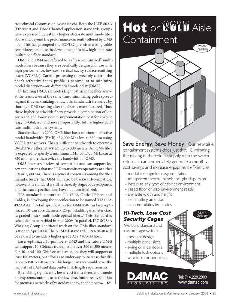
Save Energy, Save Money...Our new aisle
containment systems does just that! Eliminating
the mixing of the cold air supply with the warm
return air can immediately generate a monthly
cost savings and increase equipment efficiencies.
- modular design for easy installation
- transparent thermal panels for light dispersion
- installs to any type of cabinet environment
- raised floor or slab environment ready
- any aisle width and height
- self-shutting aisle door
- accommodates fire codes
- modular design
- multiple panel sizes
- swing or slide doors
- multiple lock options
- wire form or perf-metal
Hi-Tech, Low CostSecurity CagesWe build standard and
custom cage systems.
Tel: 714.228.2900
www.damac.com
www.cablinginstall.com Cabling Installation & Maintenance ■ January 2009 ■ 25
trotechnical Commission; www.iec.ch). Both the IEEE 802.3
(Ethernet) and Fibre Channel application standards groups
have expressed interest in a higher-data-rate multimode fi ber
above and beyond the performance currently off ered by OM3
fi ber. Th is has prompted the ISO/IEC premises wiring cable
committee to request the development of a new high-data-rate
multimode fi ber standard.
OM3 and OM4 are referred to as “laser-optimized” multi-
mode fi bers because they are specifi cally designed for use with
high-performance, low-cost vertical-cavity surface-emitting
lasers (VCSELs). Careful processing to precisely control the
fi ber’s refractive index profi le is paramount to minimize
modal dispersion—or, diff erential mode delay (DMD).
By limiting DMD, all modes (light paths) in the fi ber arrive
at the transceiver at the same time, minimizing pulse spread-
ing and thus maximizing bandwidth. Bandwidth is ensured by
thorough DMD testing aft er the fi ber is manufactured. Th us,
these higher-bandwidth fi bers provide a combination of lon-
ger reach and lower system implementation cost for current
(e.g., 10-Gbit/sec) and more importantly, future higher-data-
rate multimode fi ber systems.
Standardized in 2002, OM3 fi ber has a minimum eff ective
modal bandwidth (EMB) of 2,000 Mhz∙km at 850 nm using
VCSEL transceivers. Th is is suffi cient bandwidth to operate a
10-Gbit/sec Ethernet system up to 300 meters. An OM4 fi ber
is expected to specify a minimum EMB of 4,700 MHz∙km at
850 nm—more than twice the bandwidth of OM3.
OM3 fi bers are backward-compatible and can support leg-
acy applications that use LED transmitters operating at either
850 or 1,300 nm. Th ere is a general consensus among the fi ber
manufacturers that OM4 will also be backward-compatible;
however, the standard is still in the early stages of development
and the exact specifi cations have not been fi nalized.
TIA standards committee TR-42.12, Optical Fibers and
Cables, is developing the specifi cation to be named TIA/EIA-
492AAAD “Detail specifi cation for OM4 850-nm laser-opti-
mized, 50-μm core diameter/125-μm cladding diameter class
1a graded-index multimode optical fi bers.” Th is standard is
scheduled to be ratifi ed in mid-2009. In parallel, IEC SC 86A
Working Group 1 initiated work on the OM4 fi ber standard-
ization in April 2008. Th e A1 MMF standard 60793-20-10 will
be revised to include a higher grade A1a.3 (OM4) fi ber.
Laser-optimized 50-μm fi bers (OM3 and the future OM4)
will support 10-Gbit/sec transmission over 300 to 550 meters.
For 40- and 100-Gbit/sec transmission, they will support at
least 100 meters, but eff orts are underway to increase that dis-
tance to 150 to 250 meters. Th is longer distance would cover the
majority of LAN and data center link-length requirements.
By enabling signifi cantly lower-cost transceivers, multimode
fi ber systems continue to be the low-cost, future-ready solution
for premises networks of yesterday, today, and tomorrow.
| | | | | |Previous Page Contents Zoom in Zoom out Refer a Friend Search Issue Next Page BA
M SaGEFC7Installation MaintenanceC7
| | | | | |Previous Page Contents Zoom in Zoom out Refer a Friend Search Issue Next Page BA
M SaGEFC7Installation MaintenanceC7

| | | | | |Previous Page Contents Zoom in Zoom out Refer a Friend Search Issue Next Page BA
M SaGEFC7Installation MaintenanceC7
| | | | | |Previous Page Contents Zoom in Zoom out Refer a Friend Search Issue Next Page BA
M SaGEFC7Installation MaintenanceC7

InternetDependent station
Dependent
station
(Client)
Dependent
station
(Client)
Dependent
station
(Client)
Dependent
station
(Access point)
Enabling station (Access point)
Enabling
beacon
Enabling beacon
Enabling
beacon
Enabling
beacon
LAT 37 23518 / LON 122 02.625
75’ above the ground
Enabling station (Access point)
LAT 37 23518 / LON 122 02.625
75’ above the ground
802.11 network overview
Source: Wi-Fi Alliance
Clients
www.cablinginstall.com wireless
www.cablinginstall.com Cabling Installation & Maintenance ■ January 2009 ■ 27
In late September of last
year, the IEEE (www.ieee.
org) approved for publica-
tion the 802.11y wireless
standard, enabling high-powered Wi-Fi equipment to
operate in and “cooperative use” of the mostly vacant
3650 to 3700 MHz band. In essence, the amendment
to the 802.11-2007 standard, in conjunction with the
FCC’s (www.fcc.gov) 3650 MHz Order established in
2005, allows for increased wireless operation for more
users at a much higher power than via traditional Wi-Fi
equipment—up to 3 miles or more—and, according to
the FCC will “create a spectrum environment that will
encourage multiple entrants and stimulate the expan-
sion of broadband service,” especially in rural areas.
Th e Wi-Fi Alliance (www.wi-fi .org), a non-profi t in-
dustry association of more than 300 member companies
devoted to promoting the growth of WLANs, recently
published a discussion paper on the 802.11y standard, “A
New Regulatory and Technical Environment for Wire-
less Broadband.” In its report,
the Alliance notes that the key
intentions of the FCC order in-
clude “to lower the cost of entry
and compliance while allowing
market forces to derive maxi-
mum value from the available
spectrum through shared use.”
Th e Order requires robust co-
existence capabilities, and the
Alliance says that “Wi-Fi technology is especially well
suited to meet the requirements for avoiding interfer-
ence…Because the contention-based protocol used by
Wi-Fi technology senses and responds to a broad range
of potential technologies, 100% of the 3650 MHz band is
available to networks using the 802.11y protocol.”
Th e 3650 MHz band has been largely vacant due to
the range limitations of radio waves and intentional fre-
quency spacing to avoid interference, but the Alliance
report notes, “Th e expectation is that successful
In a typical 802.11y deployment, a
licensed operator installs a few
enabling stations over a geo-
graphically large oil fi eld, then uses
dependent stations at each truck or
rig. The enabling stations man-
age the regulatory aspects of the
network, with oversight from the
operator’s IT department.
➤
Essentials of an802.11y network
The recently approved standard will allow for
high-powered Wi-Fi-enabled communications
at distances of 3 miles or more.
STEVE SMITH is executive editor for Cabling Installation & Maintenance.
| | | | | |Previous Page Contents Zoom in Zoom out Refer a Friend Search Issue Next Page BA
M SaGEFC7Installation MaintenanceC7
| | | | | |Previous Page Contents Zoom in Zoom out Refer a Friend Search Issue Next Page BA
M SaGEFC7Installation MaintenanceC7
___
__________

28 ■ January 2009 ■ Cabling Installation & Maintenance www.cablinginstall.com
deployment of [the Wi-Fi] model in the 3650 MHz band can
and should lead to a much broader allocation of spectrum for
lightly licensed networks utilizing a contention-based pro-
tocol mechanism—eventually including most of the known
unused or underused radio spectrum.”
Light licensing means that licensees pay a small fee for a
nationwide, non-exclusive license, and then pay an additional
nominal fee for each deployed high-powered base station.
Potential installations include industrial automation and
control, campus and enterprise networks, and public safety
and security networks. In one scenario of a potential 802.11y
installation, a fi re station locates an enabling station (see
description below) on its communications tower, and uses
dependent stations on each fi re truck and
laptop. Th e incident commander controls
the enabling station using a Public Safety
band radio.
Wi-Fi Alliance discussion paper excerpt
Th rough the courtesy of the Alliance, the fol-
lowing excerpts from their white paper de-
scribe the major elements and operation
overview of an 802.11y network:• Enabling stations. An enabling station is a high-powered
fi xed station with authority to control when and how a
dependent station can operate. An enabling station commu-
nicates an initial enabling signal to its dependents over the
air. Th e enabling station may then direct supporting enable-
ment messages to be exchanged over the air, over another
dependent station, or by mechanisms that rely on transport
via higher layers. As with all high-powered stations, GPS co-
ordinates and altitude information of enabling stations are
registered in a public database to enable stations experienc-
ing interference to locate interfering stations and seek inter-
ference mitigation. Enabling stations must include location
information in every beacon. • Dependent stations. Dependent stations are devices in the
network that are not registered, but instead receive authori-
zation to transmit from a registered enabling station over the
air. Failure to receive the enabling beacon at regular, defi ned
intervals requires a dependent station to suspend transmis-
sion until it is re-enabled. A dependent station may be fi xed
or mobile. • Regulatory class information. Each device in a network
must be able to operate within regulatory requirements of
any channel available to it. Prior to 802.11y, channel switch-
ing only occurred within a particular band, where only trans-
mit power limits may have changed. Future implementations
will be able to move outside of the original band, comply-
ing with the regulatory requirements specifi ed by the regula-
tory class octet in every beacon.
Together, these new elements support three signifi cant new
mechanisms defi ned in 802.11y: • Dynamic Station Enablement (DSE). [Th is is] the process
by which an enabling station grants permission and dic-
tates operational procedures to dependent stations. Th e light-
ly-licensed structure of the FCC regulations for 3650 MHz
calls for the creation of procedures to govern the use of the
band and treatment of violations. DSE supports the light-
ly-licensed regulatory model by empowering the network
operator to ensure appropriate operation of base stations
and the dependent stations they enable. Beyond addressing
the regulatory requirements for the 3650 MHz Order, DSE
off ers the promise of other channel management and coor-
dination benefi ts.1 For example, since the enabling station
is not required to serve as the access point for each of its de-
pendent stations, DSE can reduce the likelihood of a depen-
dent station contributing to radio interference by allowing
the dependent station to complete the enablement process via
a geographically closer access point and ultimately through
a channel other than the air (e.g., the Internet).1
• Contention-based protocol incorporating regulatory class
information. 802.11y devices can sense both 802.11 and non-
802.11 devices and identify available spectrum as small as
5MHz. 802.11y access point beacons identify the country
and the regulatory domain for their physical location. By
incorporating both channel use and regulatory class infor-
mation, 802.11y devices can identify available channels and
adjust operating parameters to the laws of the country in
which the access point resides. • Extended Channel Switch Announcement (ECSA). A meth-
odology to coordinate a move from one channel to anoth-
er with less contention or to change channel bandwidth.1
Specifi cally, an enabling station can identify the channel
with the least aggregate interference to all of the stations
that are connected to it on a completely dynamic basis. Th is
capability ensures the best signal-to-noise ratio and lowest
power levels possible. ECSA also incorporates regulatory
class information—if a channel switch moves the network
to a new regulatory domain, the station shift s to the approved
frequencies and channels for the new domain. ECSA orig-
inates in 802.11y, and is now being applied retroactively to
802.11n and the other proposed concepts across 802.11.
The improved quality of service (QoS) made pos-
sible by higher power levels will make Wi-Fi tech-
nology more attractive for intensive applications like
Voice over Internet Protocol (VoIP).
| | | | | |Previous Page Contents Zoom in Zoom out Refer a Friend Search Issue Next Page BA
M SaGEFC7Installation MaintenanceC7
| | | | | |Previous Page Contents Zoom in Zoom out Refer a Friend Search Issue Next Page BA
M SaGEFC7Installation MaintenanceC7

With Sentry™!
©Server Technology, Inc. Sentry is a trademark of Server Technology, Inc.
Solutions for the Data Center Equipment CabinetHow Do You Monitor,Distribute & ControlHigh Density CabinetPower In-Feeds?
Switched & Smart 3-Phase Power Distribution Units
> High Power Distribution208V 3-Phase 30A/60A or 400V 3-Phase 16A/32A
> Flexible MountingZero U or Modular mounting inside the cabinet
> Delta or Wye In-FeedsWye in-feeds can also provide 120V power outputs
> Multiple Outlet TypesIEC C13, C19 & NEMA 5-20R outlets in multiple configurations
> Local Current LED’sVerification of input current and for load balancing
> Environmental MonitoringExternal temperature & humidity probes.
> LinkingLinks (2) units with (1) IP address for Remote Monitoring
> Remote Control, Monitoring and SecurityWeb interface, SSL, SSH, Telnet, SNMP, FTP, SNTP,Syslog, LDAP & LDAPS, TACACS+ & RS-232 access
Server Technology, Inc. / Headquarters1040 Sandhill DriveReno, NV 89521–USA
tf +1.800.835.1515tel +1.775.284.2000fax +1.775.284.2065
www.cablinginstall.com Cabling Installation & Maintenance ■ January 2009 ■ 29
Network operation overview
Th e fi rst requirement for establishing an IEEE 802.11y network
is determining if the area to be covered is in an exclusion zone.
If it is outside of the protected regions, the network operator
must fi le for a license, pay a small fee, and regis-
ter the location of the enabling station in a public
database. Dependent stations, fi xed and mobile,
may then be added to the network based on their
ability to receive and decode the enabling beacon.
Once enabled, each dependent station continually
tests its ability to receive and decode an enabling
beacon. Failing this test, the dependent station at-
tempts to reacquire the beacon, with a fi nite number of attempts
before ceasing trying for a predetermined amount of time.
Th is requirement prevents congestion caused by stations that
may be truly out of range of an enabling beacon. Enabling
stations continually test for interference. If interference is de-
tected, the enabling station must silence the network and
search for a clear channel. When a new channel is identifi ed,
ECSA directs all of the devices in the network to move to the
new channel, which may include a change in regulatory class,
as specifi ed by the regulatory class octet.
Potential installations include industrial automa-
tion and control, campus and enterprise net-
works, and public safety and security networks.
Low-cost chipsets and the capability to eff ectively man-
age interference through contention-based protocols make
Wi-Fi technology an excellent fi t for applications in this spec-
trum. Th e improved quality of service (QoS) made possible by
higher power levels will make Wi-Fi technology more
attractive for intensive applications like Voice over Internet
Protocol (VoIP).
Ed. note—Th e complete discussion paper may be viewed at:
http://wi-fi .org/fi les/kc/WFA_11y_Primer_fi nal.pdf
References
1. Blue, Scott. 2008. Th e Sensible Guide to 802.11y. Sensible Ra-
dio Corp. (www.sensibleradio.com/11y.pdf)
| | | | | |Previous Page Contents Zoom in Zoom out Refer a Friend Search Issue Next Page BA
M SaGEFC7Installation MaintenanceC7
| | | | | |Previous Page Contents Zoom in Zoom out Refer a Friend Search Issue Next Page BA
M SaGEFC7Installation MaintenanceC7
_________________________________

Almost every day you’re asked to make on-the-job compromises. But compromise the performance of your network? Not a chance.
Build a better network with NextLAN Systems. Gain the benefits of two industry leaders combining their expertise to jointly engineer, manufacture and support a broad range of structured cabling systems. NextLAN connectivity and cables are independently tested - as a system - to ensure repeatable performance. And NextLAN systems are backed by a lifetime warranty*. Visit www.NextLANsystems.com for more information.
*Limited lifetime channel and product warranty on all certified installations. © 2008 Leviton Manufacturing Co., Inc. and Superior Essex Inc. All Rights Reserved.
PERFORMANCE WITHOUT COMPROMISE
| | | | | |Previous Page Contents Zoom in Zoom out Refer a Friend Search Issue Next Page BA
M SaGEFC7Installation MaintenanceC7
| | | | | |Previous Page Contents Zoom in Zoom out Refer a Friend Search Issue Next Page BA
M SaGEFC7Installation MaintenanceC7

Compiled by Steve Smith
wwww.cablinginstall.com Cabling Installation & Maintenance ■ January 2009 ■ 31
When Miami, FL-based Concord
Electric Contractors was tasked
to upgrade the computer and media in-
frastructure for the Immaculata-LaSalle
High School, the limited room for cable
runs presented an installation challenge.
Concord found the solution in Isotec’s
(www.isotec.com) new SIMTRA Ferrite-
Barrier power cables, which are designed
to be both a space and time saver.
“Th e Immaculata-LaSalle installa-
tion posed signifi cant design issues be-
cause of the lack of space to run wires,”
says David Linenfelser, electrical su-
pervisor at Concord Electric Contrac-
tors. “Th e Isotec SIMTRA power cables
became the only solution for the instal-
lation because the unique design of the
SIMTRA wire allows for multi-format
media and low-voltage cabling to co-ex-
ist in the same conduit as the 120 volt AC
power cable without interference, while
only having to run one cable.”
SIMTRA cables conform with NEC
specifi cation sections 725.136, 760.136,
770.133, 800.133, 800.179, 820.133 and
830.133, and are designed to elimi-
nate transients and interference. Each
conductor of the power cable is sur-
rounded by a proprietary ferrite bar-
rier that provides shielding within the
cable itself, thereby attenuating surges and
minimizing interference that can corrupt
the signal in adjacent low-voltage cables.
Th e Immaculata-LaSalle project re-
quired several diff erent types of cable
to be run to each classroom. For in-
stance, each classroom has cables run-
ning to the teacher’s desk that provide
interconnections for the video projec-
tor, DVD, audio amplifi er and comput-
er networking, in addition to power for
each student desk.
Barrier cable technology allows forpower, low-voltage in one conduit
Survey: wireless is hottest thing on campus
➤
Proprietary design of Isotec Inc.’s SIMTRA wire allows for
multi-format media and low-voltage cabling to co-exist
without interference in the same conduit as a 120 volt AC
power cable.
Power outlets for each stu-
dent computer were posi-
tioned next to each desk, but
there was not space available
for multiple conduit runs. By
using SIMTRA power ca-
bles, however, Concord Elec-
tric Contractors was able to
pull the projector wiring, TV
cable, speaker wire, data
cable, and AC power all in
one conduit into the room,
breaking out Category 5 Eth-
ernet cable and AC for the
individual student stations.
Also, since the cable could be
run through the small space
in the fl oor, installers were
able to eliminate the extra
step of supporting the cables every four
feet— required when running low-volt-
age cable through ceilings.
“A big benefi t of the SIMTRA cable is
time savings on a job and streamlining
the installation to meet code,” explains
Linenfelser. “Also, whenever you go
through a classroom wall, the building
codes consider it a fi rewall, and that
requires a whole new set of rules. What’s
benefi cial with SIMTRA is that we actu-
ally run one large conduit from the class-
rooms to the main room where the high
voltage and low voltage all converge,
eliminating the need for multiple pene-
trations of the fi rewalls. [For] Immacu-
lata-LaSalle, SIMTRA cable actually
made this installation possible.”
Arecent survey indicates that near-
ly three out of four colleges and
universities plan to expand their wire-
less networks over the next two years.
Th at is one of the key fi ndings in the lat-
est member survey by ACUTA (www
acuta.org), the Association for Informa-
tion Communications Technology Pro-
fessionals in Higher Education, which
surveyed members at its 2008 Fall Sem-
inar in Boston.
Th e survey asked members to iden-
tify the most signifi cant change in their
cabling and wiring infrastructure over
the last several years. Sixty percent said
that change was deployment of wireless
networks, compared with 13% pointing
to installation of fi ber-optic cable and
another 13% citing rewiring projects for
technology upgrades.
Two out of three survey respon-
dents said it was the demand for
“connectivity anywhere” that drove their
key networking change, while 40%
| | | | | |Previous Page Contents Zoom in Zoom out Refer a Friend Search Issue Next Page BA
M SaGEFC7Installation MaintenanceC7
| | | | | |Previous Page Contents Zoom in Zoom out Refer a Friend Search Issue Next Page BA
M SaGEFC7Installation MaintenanceC7
___
______

32 ■ January 2009 ■ Cabling Installation & Maintenance www.cablinginstall.com
ARLINGTON, VA—The Telecommunications Industry Association
(www.tiaonline.org) has updated the 568-C.3 Optical Fiber
Cabling Components standard, which specifi es cable and
component transmission performance requirements for premises
optical-fi ber cabling. Signifi cant technical changes include:
incorporating the performance specifi cations for 850nm laser-
optimized 50/125-μm multimode cables previously found in
ASNI/TIA/EIA-568-B.3-1; specifi cations for indoor-outdoor cable,
including minimum bend radius and maximum pulling tensions;
and array connector specifi cations. Copies of the document are
available at: www.global.ihs.com
STERLING, VA— As the data center continues to evolve and
mature, business-oriented goals are driving the adoption of
Ethernet as the single network technology, according to a new
Current Analysis Advisory Report, “One Love, One Data Center,
One Network.” According to the report’s
author, Steven Schuchart, Current Analysis principal analyst/
data center, “For there to be truly agile, cost optimized, and
effi cient data centers, the network must be transitioned to a
single technology. That technology is Ethernet. There is signifi cant
opportunity to break the old networking paradigms and advocate
one network technology for the data center.” In the report,
Schuchart looks at why Ethernet is the natural choice for a single
network, including its wide deployment, and the willingness of
Ethernet’s vendors to work together to ensure that the technology
is compatible, regardless of brand or origin. For a complimentary
copy of the full report, visit: www.currentanalysis.com/f/2008/
onenetwork/
LITTLE NECK, NY—In February, Leviton (www.leviton.com) will
open a new 450,000-square-foot distribution center in Lebanon,
TN. The fully automated facility will serve as one of the company’s
two state-of-the-art domestic warehouse and distribution
hubs. The Tennessee center will service customers east of the
Mississippi River, and feature the company’s commercial-grade
occupancy sensors, light switches, outlets, and commercial
networking devices.
ANAHEIM, CA—To help facilities managers and engineers
address power issues, Electrorack (www.electrorack.com)
has designed a downloadable Power Distribution Catalog that
highlights a wide selection of Power Distribution Units (PDUs),
power consumption monitoring solutions, and mounting methods.
Electrorack’s PDU options are designed to give facilities managers
the ability to closely monitor current draw, and determine where
and how to distribute power via a selection of current, voltage,
mounting options and plug types. Voltage ranges are 120, 208,
208/3-Phase), and amperage ranges are 15, 20, 30, 50 and 60.
Short runs…
said the evolution of communication
styles was a major factor. Meeting grow-
ing capacity needs and migration to Voice
over IP and Unifi ed Communications
were other drivers cited, at 33% and 23%
respectively.
Th e single greatest benefi t of their
change, said responding ACUTA mem-
bers, was network access anywhere and
anytime (42%); user convenience (23%);
network effi ciencies (17%); and greater
bandwidth (10%).
On the downside, 56% of respondents
said the cost of their change was their
greatest challenge, while another 21%
said locating and installing the many
wireless access points needed for cover-
age was their biggest hurdle.
Asked about the next signifi cant step
in their campus networking, 71% said
expansion of their wireless network—or
installation of one if they haven’t done so
already—is in their plans. Another 19%
pointed to additional rewiring projects
as information communications tech-
nology evolves. As far as the timeframe
for their next big steps, 73% of respon-
dents expect to take those steps within
one year.
Finally, asked to identify how their
ongoing changes aff ect both them and
their departments, respondents said
the highest impact issues are ever-tight-
ening budgets, a greater need for long-
range planning, the need to learn new
technology skills, the fact that growing
campuses mean more responsibility for
their departments, and the challenge of
fi nding employees with the right mix of
skills.
“The fact that wireless network-
ing is the biggest change for our mem-
bers and their schools isn’t surprising in
itself,” says Jeri Semer, executive director
of ACUTA. “But this survey shows the
impact that wireless networks, as well as
other forms of technology evolution, are
having on information communications
technology departments.”
Semer adds, “While wireless net-
works do make communications and
computing far more convenient on cam-
puses, they do have their challenges in
terms of cost and management. Th e
same is true for other advancing tech-
nologies as well.”
“While wireless networks do make communications
and computing far more convenient on campuses,
they do have their challenges in terms of cost and
management.”
| | | | | |Previous Page Contents Zoom in Zoom out Refer a Friend Search Issue Next Page BA
M SaGEFC7Installation MaintenanceC7
| | | | | |Previous Page Contents Zoom in Zoom out Refer a Friend Search Issue Next Page BA
M SaGEFC7Installation MaintenanceC7
_______
wwww.cablinginstall.com Cabling Installation & Maintenance ■ January 2009 ■ 33
High-speed networking alliances plan to merge
The Ethernet Alliance (www.
ethernetalliance.org) and the Road
to 100G Alliance plan to transition as
one organization under the Ethernet
Alliance. Both industry organizations
promote the advancement of high-per-
formance Ethernet networking.
Th e non-profi t Road to 100G Alliance
seeks to provide seamless interopera-
bility among the disparate, standards-
based components required to build
high-capacity network elements. Th e
Ethernet Alliance seeks to promote
industry awareness, acceptance, and
advancement of technology and prod-
ucts based on existing and emerging
IEEE 802 Ethernet standards.
“Th e Road to 100G Alliance has met
and exceeded its expectations in terms
of exposing the challenges of develop-
ing 100G platforms,” says Bill Weisinger,
chairman of the Road to 100G Alliance.
“With the challenges well understood, it
is the right time for us to join with the
Ethernet Alliance and fulfi ll the balance
of our goal—to establish a comprehen-
sive ecosystem of suppliers and users
to accelerate the adoption and ongoing
development of high-performance net-
working solutions.”
Brad Booth, chairman of the board
for the Ethernet Alliance, notes, “Th e
demand for bandwidth is growing in ev-
ery market segment—from consumer to
enterprise to service and content provid-
ers. Th e Ethernet Alliance praises the
Road to 100G Alliance and its members
on highlighting the challenges of 100G
and is honored they believe the Ether-
net Alliance is the organization to fur-
ther their goal.”
Booth adds, “Given the alignment of
our visions and strategies, the combina-
tion of our two organizations will greatly
advance the development of the high-
speed Ethernet ecosystem, benefi ting
customers worldwide.”
In November 2007, the IEEE 802.3
working group authorized the forma-
tion of the IEEE P802.3ba task force to
begin work on a draft standard for 40
Gigabit and 100 Gigabit Ethernet. Late
last fall, the task force completed review
of the fi rst draft of IEEE P802.3ba, which
keeps the task force on track for standard
ratifi cation by mid-2010.
The Ethernet Alliance has also
announced an internship program as
part of its Ethernet Alliance Univer-
sity Program (EAUP). Th e program
promotes internship opportunities by
connecting corporate members with cur-
rently enrolled student of EAUP aca-
demic members. Th e Alliance accepts
student resumes and makes them avail-
able to corporate members via its online
database.
“As someone who graduated from a co-
operative engineering program, I know
that today’s university students will have
a direct infl uence on helping shape Eth-
ernet technologies in the years to come,”
says Booth.
TAMPA, FL—This month, BICSI (www.bicsi.org) will inaugurate
fi ve new board members elected to serve 2-year terms on the
board of directors. Members approved: Christine Klauch, RCDD,
NTS as secretary; Mel Lesperance, RCDD, as U.S. Southeast
Region director; Michael Collins, RCDD, U.S. South-Central
Region director (incumbent); Todd Strand, RCDD, NTS, OSP,
U.S. Western Region director; Richard Smith, RCDD, NTS, OSP,
Canadian Region director (incumbent).
LEXINGTON, KY—ACUTA, the Association for Information
Communications Technology Professionals in Higher Education
(www.acuta.org) has moved its annual conference from
summertime to April 19-22 at the Hyatt Regency Atlanta, GA.
“Summer is a very busy season for major technology projects on
campus, so we were receiving feedback from members that it was
diffi cult for them to get to the annual conference in the summer
months,” says executive director Jeri Semer. The conference and
13th annual forum will emphasize technology and management
education, information sharing, and networking among peers.
BEAVERTON, OR—The International Telecommunication Union’s
Standardization Sector (ITU-T) has consented the PHY and
architecture portions of the ITU-T G.hn specifi cation, as part
of standardization efforts for next-generation home networking.
According to HomeGrid Forum (www.homegridforum.org), the
consent demonstrates momentum for G.hn as a worldwide
standard that will unify the networking of content and devices over
any wire—coax cable, phone, and power lines.
Short runs…
“The demand for bandwidth is growing in every
market segment—from consumer to enterprise to
service and content providers.”
| | | | | |Previous Page Contents Zoom in Zoom out Refer a Friend Search Issue Next Page BA
M SaGEFC7Installation MaintenanceC7
| | | | | |Previous Page Contents Zoom in Zoom out Refer a Friend Search Issue Next Page BA
M SaGEFC7Installation MaintenanceC7
______________
____

Recently Archived Events
■ TIA Standards UpdateSponsored by: APC, Berk-Tek, Chatsworth Products and Harger
■ 10GBase-T Technology and
Systems Update
Sponsored by: Belden, Fluke Networks and Panduit
■ Wireless LAN: Standards, Architectures,
Testing
Sponsored by: Fluke Networks, Microsemi and Ortronics
■ Green Cabling
Sponsored by: ADC, Berk-Tek, Chatsworth Products, Corning and Ortronics
■ 10-Gigabit Cost Comparisons
Sponsored by: Berk-Tek, Ortronics and Tyco Electronics
To view archived Webcasts now, visit: www.cablinginstall.com/webcast
| | | | | |Previous Page Contents Zoom in Zoom out Refer a Friend Search Issue Next Page BA
M SaGEFC7Installation MaintenanceC7
| | | | | |Previous Page Contents Zoom in Zoom out Refer a Friend Search Issue Next Page BA
M SaGEFC7Installation MaintenanceC7

www.cablinginstall.com Cabling Installation & Maintenance ■ January 2009 ■ 35
Compiled by Steve Smith New Products
High-def signal extenderThe AT-HDRS is a HDMI over
CAT5/5e/6 receiver unit designed to
work with the AT-HD19SS, Atlona’s new
HD video distribution system. Th is unit
lets users deploy additional HD moni-
tors as their AV system expands. Th e
AT-HD19SS, when combined with the
AT-HDRS, is designed to form a fl exi-
ble, expandable solution by which high
defi nition video and audio can be rout-
ed to multiple remote displays. Th ese
units take HD video at resolutions up
to 1080p over a HDMI 1.2a connection,
and then extend that signal over a sin-
gle CAT5/5e/6 cable up to 200 feet. At
each display end, the cable is connected
to the AT-HDRS receiver units that fea-
ture an adjustable equalizer, which the
company claims “ensures perfect sig-
nal quality with no degradation.” Th e
AT-HD19SS and AT-HDRS HD vid-
eo distribution system can be cas-
caded, allowing for an infinite
number of display locations. Th ese
units are suitable for in-store
video displays, digital signage, as well as
education and worship facility installa-
tions. Expected MSRP is $149 each.
ATLONA TECHNOLOGIES
www.atlona.com
Data center UPSAPC’s Symmetra PX 250/500kW Th ree-
Phase uninterruptible power sup-
ply (UPS) system for the data center
is designed for ultra-high effi ciency,
nearly silent operation and N+1 redun-
dancy. Th is modular power solution is
built for growth-oriented high density
and higher power installations look-
ing to maximize virtualization eff orts
in the data center. Th e APC Symmetra
PX 250/500kW off ers 25kW ultra-high
effi ciency double conversion online
inverter power modules, extended life
hot-swap batteries, a large touch-screen
graphical user interface, and a side-
mounted maintenance bypass panel
with subfeed distribution. It also off ers
maximum data center confi guration
fl exibility, allowing the unit to fi t in the
same row as IT equipment, or against
a wall to save fl oor space. In the future,
APC says the Symmetra PX 250/500kW
will be capable of being paralleled up to
2 MW. Th e system also features auto-
mated predictive diagnostic capabili-
ties, increased overload capacity, and
on-the-fl y fi rmware upgrades, which are
designed for highly redundant, effi cient,
and simplifi ed UPS architecture.
APC/SCHNEIDER ELECTRIC
www.apcc.com
HDTV network cameraTh e AXIS Q1755 Network Camera is de-
signed for securing areas where greater
image detail is required, such as airports,
passport controls, and casinos. It is built
for HDTV 1080i or 720 resolution, 16:9
aspect ratio, and supports both H.264 and
Motion JPEG in full frame rate. With day
and night functionality and progressive
output, this camera is designed to pro-
vide exceptional quality images even of
fast moving objects in all lighting con-
ditions. It features 10x optical zoom
and 12x digital zoom paired with auto
focus. Th e AXIS Q1755 includes video
intelligence, such as enhanced video
motion detection, audio detection, and
detection of camera tampering (such
as blocking or spray-painting). In addi-
tion, it incorporates a Gatekeeper func-
tionality, which automatically zooms in
when there is activity in the scene and
then zooms out aft er a preset time inter-
val. Th e camera off ers an advanced suite
of security and network management
capabilities, including HTTPS encryp-
tion, IEEE 802.1X authentication, IPv4/
IPv6 and Quality of Service.
AXIS COMMUNICATIONS
www.axis.com
Passive cooling exhaust ductConfi gurable heights and a collapsible
design are now off ered in the Vertical
Exhaust Duct, a passive cool-
ing solution used with the
company’s F-Series Tera-
Frame cabinet system. It
isolates and guides hot ex-
haust air from the back
of the cabinet to the
drop ceiling plenum,
creating a closed hot
air return path to
the cooling system.
Airfl ow is not lim-
ited to fan capacity,
and there are no ad-
ditional power costs,
fan replacements, or
power redundancy
requirements. With a
2-piece telescoping design, the Ver-
tical Exhaust Duct meets varying ceil-
ing height requirements; it is available
in a short version, extending from 20 to
34 inches for low ceilings, and a tall ver-
sion reaching 34 to 60 inches. A fl exible
gasket creates a seal around the opening
in the drop ceiling, eliminating the need
for ceiling grid alterations.
CHATSWORTH PRODUCTS
www.chatsworth.com
| | | | | |Previous Page Contents Zoom in Zoom out Refer a Friend Search Issue Next Page BA
M SaGEFC7Installation MaintenanceC7
| | | | | |Previous Page Contents Zoom in Zoom out Refer a Friend Search Issue Next Page BA
M SaGEFC7Installation MaintenanceC7

www.usconec.com
800 769 0944
US Conec offers standards based and contract manufactured products for all of your high density optical connectivity needs.As leaders in multi-fiber connector technology, we are constantly expanding our product offerings using over 15 years ofexperience in materials, precision molding and advanced metrology.
IBC™
Brand Cleaners
• Cost effective dry cleaning solutions for connectors residing in bulkhead adapters and unmated on cable assemblies
• Highly effective for removal of oil, dust, solvent residue and a host of other common contaminants encountered during installations
• IBC™ Brand Cleaner SC for 2.5mm connectors is designed for SC, ST, FC and E2000 with UPC & APC polishes
• IBC™ Brand Cleaner LC for 1.25mm connectors is designed for standard LC and MU with UPC & APC polishes
• IBC™ Brand Cleaner MPO is designed for male and female MPO compatible connectors including MTP®
Brand connectors
New Products
Cabling distribution systemFor high performance and fl exible copper or fi ber-optic cabling
in server rooms and data centers, this modular distribution sys-
tem is available in
1U and 3U heights,
in stainless steel or
with black lacquer-
ing, and equipped
with distribution
boxes to terminate
the thin trunk cables.
Copper distribution
boxes provide RJ-45 ports at the front and a Telco adapter or
LSAplus contacts at the rear. Fiber-optic boxes provide an MPO
adapter as rear input and an internal fi ber duct to the front side
fi ber-optic ports. Th is system lets you complete up to 48 pre-ter-
minated fi ber-optic or copper ports per height unit. Th e copper
solution allows a 10 Gbit/sec data transfer a maximum distance
of 60 meters, while the fi ber solution lets you transfer up to
10 Gbits/sec with a maximum permanent link length of 90
meters. By using pre-connected, thin trunk cables, this distribu-
tion subsystem allows for simplifi ed changes or extensions that
can be performed without interruption of operations.
DAETWYLER CABLES
www.daetwyler-cables.com
Hardened, bend-insensitive fi berDraka Communications has developed advanced connectorized
cables through the combination of the company’s BendBright-
XS bend-insensitive fi ber cable and Megladon’s Hardened Lens
Connector (HLC) ScratchGuard connector technology. Avail-
able immediately in patch cord products, the solution is de-
signed as a high performance, scratch-resistant, bend-insensitive
fi ber-optic cable assembly. Riser, plenum, and low-smoke zero
halogen (LSZH) cables are available with ultra or angle polish
hardened lens connectors.
DRAKA COMMUNICATIONS
www.drakaamericas.com
Wall-mount boxesOWB-X outdoor wall
boxes are designed for
audio/visual, IT and con-
trol installations. Covers
have “fl ip up” cable entry
doors so that the main
cover door can be locked
once the cables are con-
nected. Two box styles
are available that will
| | | | | |Previous Page Contents Zoom in Zoom out Refer a Friend Search Issue Next Page BA
M SaGEFC7Installation MaintenanceC7
| | | | | |Previous Page Contents Zoom in Zoom out Refer a Friend Search Issue Next Page BA
M SaGEFC7Installation MaintenanceC7

OFS’ LaserWave fiber exceeds the OM3 standard for today’s high-speed networks — and tomorrow’s. And since LaserWave fiber delivers DMD specified in the 0 – 5 micron range, you get up to twice the bandwidth for lasers that launch power in the fiber’s center. Enjoy fast, reliable transmission and easier connectivity. To learn more, ask your cabler about OFS or visit ofsoptics.com/fiber.
Get your network up to speed with LaserWave® fiber.
New Products
www.cablinginstall.com Cabling Installation & Maintenance ■ January 2009 ■ 37
allow for either fl ush “in wall” or sur-
face “on wall” mounting. Th e back box
is currently available with four diff er-
ent connector mounting confi gurations.
Th e internal connector mounting styles
handle standard gang plates, the compa-
ny’s assortment of IPS inserts, and XLR-
type connectors. A blank plate is supplied
for custom fabricating. Th e enclosures are
constructed in NEMA-4 style and with
the integral door will meet the NEMA-3
and 3R ratings providing protection
against falling dirt, rain, sleet and snow.
Locking doors in brushed aluminum
are standard, with other color and style
options available upon request.
FSR
www.fsrinc.com
Visible fault locatorTh is handheld visible fault locator (GAO
811) is designed to fi nd faults in fi ber
jumpers, patch panels, enclosures, con-
nectors and couplers. Th e fault location
is made visible from a macro bend point,
break, problem coupler or connector, or a
mechanical splice that is not well aligned.
GAO 811 handheld laser source is able to
remedy the limitation of the dead zone of
an OTDR and detect fi ber fault positions
accurately. It is suitable for optical net-
work installation and maintenance.
GAO TEK INC.
www.gaotek.com
Panel-mount cable tieTh e 7x12-mm Fir Tree Push Mount Tie
features a fi r tree design that provides
a single mounting solution for a wide
range of cable and wire bundling appli-
cations, specifi cally mounting wire har-
nesses in oval and rectangular 7x12-mm
panel holes and blind assembly holes. Th e
fi r tree base locks and secures the bun-
dle onto the panel by latching onto the
opposite side of the panel surface. Th e
disc on top of the fi r tree covers the in-
sertion hole, reducing the ingress of dust,
dirt, and water. Th e outside serrated tie,
with 50-pound tensile strength, comes in
two strap lengths to accommodate bun-
dle sizes from 6.5 to 8.5 inches.
HELLERMANNTYTON
www.hellermann.tyton.com
| | | | | |Previous Page Contents Zoom in Zoom out Refer a Friend Search Issue Next Page BA
M SaGEFC7Installation MaintenanceC7
| | | | | |Previous Page Contents Zoom in Zoom out Refer a Friend Search Issue Next Page BA
M SaGEFC7Installation MaintenanceC7

38 ■ January 2009 ■ Cabling Installation & Maintenance www.cablinginstall.com
New Products
Rack cooling solutionHewlett Packard’s HP 10K G2 Air Duct
rack cooling solution is designed to
eliminate ex-
isting hot spots
and optimize
air cooling in
the data cen-
ter, and mini-
mize hot and
cold air mixing
together. This
rack cool-
ing solution
suits racks us-
ing 5 to 14 kW
power. Th e air
duct is adjust-
able for diff er-
ent top ceiling
plenum heights
and has no fans
or moving parts.
It uses pressure
from the com-
puter room air
conditioning (CRAC) unit to extract air
from the rack. Th e unit can be retrofi tted
to existing problem racks and can work
with single or multiple racks.
HEWLETT PACKARD
www.hp.com/go/infrastructure
FTTx visual fault locatorsTh e pocket-sized FFL-050 fi ber fault
locator and FFL-100 visual fault loca-
tors are designed for simplifi ed trouble-
shooting of fi ber-optic cabling, espe-
cially for FTTx installations. Th e tools
are de-signed to quickly locate such
problems as sharp bends, breaks, bad
splices, lack of continuity, and fi ber
damage. Th ese fault locators emit a vis-
ible laser light into the fi ber, and as the
light escapes from the damaged points
along the fi ber in a continuous or fl ash-
ing illumination, technicians can quickly
diagnose, troubleshoot, and fi x a prob-
lem. Th e FFL-050 and FFL-100 VFL are
equipped with a 2.5-mm interface, com-
patible with such connectors as SC, ST,
and FC; a 1.25-mm adapter enables con-
nection to LC and MU connectors. Th ese
VFLs can also be used to perform end-to-
end continuity tests and fi ber tracing and
identifi cation.
JDSU
www.jdsu.com
Unifi ed camera solutionMaestro is a two-module unifi ed cam-
era solution designed for simplifi ed secu-
rity installation and setup. Th e P800 mas-
ter controller interfaces with encoders
and I/O, and provides microsecond syn-
chronization, power, and safety on Cat-
egory 5e cables for up to eight or more
cameras and light sources—all from a
single power supply. Th e P800 handles
all timing, triggering, synchroniza-
tion, sorting, and reject activations. Th e
C12 connecting module is a camera and
light controller, connected to the P800
with a 100-meter (maximum) Category
5e cable. Th is module powers and trig-
gers any camera while providing syn-
chronized confi gurable high current
pulses for LEDs or lasers. Maestro mod-
ules are compatible with all cameras, light
sources, I/O, and machine vision soft -
ware libraries, and suited for single
camera to multi-camera Web inspec-
tion systems.
LMI TECHNOLOGIES
www.LMItechnologies.com
WAP ceiling enclosuresTwo new plenum-rated ceiling enclosures
are designed specifi cally for Aruba Net-
works’ wireless enterprise deployments,
and are designed to provide a secure, and
aesthetic means to mount the access point.
Model 1052-AN (pictured) is designed for
Aruba Networks’ AP-60, 70, 120 and 124
access points with detachable antennas.
Th e 1052-AN door also has mounting lo-
cations for AP-ANT-13B antennas. Mod-
el 1055-AN is designed for the AP-65, 121,
and 125 access points with non-detach-
able antennas. Th e 1055-AN features an
impact resistant, RF transparent ABS
dome through which the non-detach-
able antennas can transmit. Both models
have locking doors and are UL-listed.
OBERON INC.
www.oberonwireless.com
Cable identifi er, organizerPatchSee is a cable identifi er system that
is also designed to solve disorganized
cable rack conditions. Th e design incor-
porates two plastic optical fi bers built in
to standard Category 5, 6 and 6A patch
cords, along with LED light injection.
Users can identify and secure both ends
of a patch cord without tracing cables
or disconnections. PatchSee also helps
defi ne various cable line functions by
| | | | | |Previous Page Contents Zoom in Zoom out Refer a Friend Search Issue Next Page BA
M SaGEFC7Installation MaintenanceC7
| | | | | |Previous Page Contents Zoom in Zoom out Refer a Friend Search Issue Next Page BA
M SaGEFC7Installation MaintenanceC7
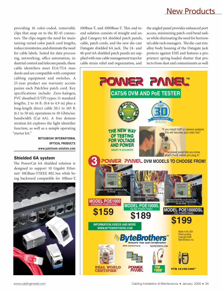
New Products
www.cablinginstall.com Cabling Installation & Maintenance ■ January 2009 ■ 39
providing 16 color-coded, removable
clips that snap on to the RJ-45 connec-
tors. Th e clips negate the need for main-
taining varied color patch cord lengths,
reduce inventories, and eliminate the need
for cable labels. Suited for data process-
ing, networking, offi ce automation, in-
dustrial control and telecom panels, these
cable identifi ers meet EIA/TIA stan-
dards and are compatible with computer
cabling equipment and switches. A
25-year product use warranty accom-
panies each PatchSee patch cord. Key
specifications include: Zero-halogen,
PVC sheathed (UTP) types; 11 standard
lengths, 2 to 16 ft . (0.6 to 4.9 m) plus a
long-length direct cable 20.1 to 165 ft .
(6.1 to 50 m); operations to 10-Gbits/sec
bandwidth (Cat 6A). A free demon-
stration kit explores the light identifi er
function, as well as a sample operating
“starter kit.”
MITSUBISHI INTERNATIONAL
OPTICAL PRODUCTS
www.patchsee-solution.com
Shielded 6A systemTh e PowerCat 6A shielded solution is
designed to support 10 Gigabit Ether-
net/ 10GBase-T/IEEE 802.3an while be-
ing backward compatible for 10Base-T,
100Base-T, and 1000Base-T. Th is end-to-
end solution consists of straight and an-
gled Category 6A shielded patch panels,
cable, patch cords, and the new die-cast
Datagate shielded 6A jack. Th e 24- and
48-port 6A shielded patch panels are sup-
plied with rear cable management trays for
cable strain relief and organization, and
the angled panel provides enhanced port
access, minimizing patch cord bend radi-
us while eliminating the need for horizon-
tal cable rack managers. Th e die-cast zinc
alloy body housing of the Datagate jack
protects against EMI and features a pro-
prietary spring-loaded shutter that pro-
tects from dust and contaminants as well
| | | | | |Previous Page Contents Zoom in Zoom out Refer a Friend Search Issue Next Page BA
M SaGEFC7Installation MaintenanceC7
| | | | | |Previous Page Contents Zoom in Zoom out Refer a Friend Search Issue Next Page BA
M SaGEFC7Installation MaintenanceC7
_______________
_______

New Products
40 ■ January 2009 ■ Cabling Installation & Maintenance www.cablinginstall.com
CLASSIFIED
Cabling in Canada?
Call
416-222-0617www.connectivitywerx.com
as ejects improperly seated patch cords.
Th e Datagate shielded jack has been de-
signed for high-speed data transmissions,
with typical applications including da-
ta centers, storage area networks, server
farms, and riser backbones.
MOLEX
www.molexpn.com
Mini Ethernet converterTh e miConverter GX/T is a 1000Base-X
Fiber to 10/100/1000Base-T Ethernet
media converter and, according to the
manufacturer, is the fi rst miniature un-
managed media converter that supports
Gigabit jumbo frames up to 10,240 bytes.
As newer IP networks move towards us-
ing jumbo frames to reduce network over-
head and to reduce CPU utilization, the
miConverter GX/T is designed to pro-
vide top performance and aff ordability
for what previously was exclusive to more
expensive Ethernet equipment. Th e mi-
Converter GX/T supports Small Form
Pluggable (SFP) transceivers for standard
and CWDM wavelengths, as well as a va-
riety of fi xed fi ber connectors. It is pow-
ered by any PC, laptop or other device
with a high-powered (1.0, 1.1 and 2.0) USB
port, and is also available with external
U.S. and international AC power supplies.
Th e international model features optional
interchangeable connectors for compati-
bility with the diff erent electrical outlets
found around the world. Th e GX/T deliv-
ers plug-and-play installation with gigabit
fi ber auto-negotiation supporting connec-
tivity found in many core fi ber devices,
and manual confi guration to support leg-
acy gigabit fi ber devices.
OMNITRON SYSTEMS TECHNOLOGY
www.omnitron-systems.com
Secured connectorSecure Keyed LC Fiber Solutions are
designed to help maintain the integrity
and security of critical information net-
works by preventing inadvertent or un-
authorized access to optical fi ber network
ports. Th e solutions are built to provide
a simplifi ed way to physically prevent
unauthorized connections by blocking
access to specifi c optical ports, whether at
a workstation outlet or in a telecommu-
nications room or data center. Th ey are
built around a core set of secure keyed
duplex LC adapters and connectors, as
well as a set of MPO 12-fi ber adapters
and connectors. Th e LC duplex and MPO
adapters, along with their matching
secure keyed connectors, have a propri-
etary built-in keying feature designed
to prevent tampering and access to re-
stricted networks. Th e keying feature
cannot be reproduced inside a standard
LC adapter or connector. Th ese secure
keyed components are especially suited
for sites that have multiple co-located
networks that need separate security
access in areas such as offi ce worksta-
tions, telecommunications wiring clos-
ets, and Internet service access facilities.
ORTRONICS/LEGRAND
www.ortronics.com
Fiber for extreme bendsCasaLight Xtreme bend optimized
fi ber is targeted at demanding FTTH
applications.
It is designed
for horizontal
cabling from
the riser shaft
to the fi rst point
of presence in-
to the customer
premises, where
the pathway
would encoun-
ter bending ra-
dii down to
7.5 mm. In the
most demand-
ing applica-
tions, CasaLight
Xtreme allows for bending radii down to
5 mm, and has been designed to with-
stand 90º bends under tension as well as
installation with staple guns when used
in Prysmian specialty MDU cables. It
maintains full compatibility with stan-
dard equipment, connectors, and fi ber
already installed in accordance with ITU
Recommendation G.652.Hi.
PRYSMIAN CABLES & SYSTEMS
www.prysmian.com
Fiber cassette enclosuresOpticom QuickNet rack-mount fi ber
cassette enclosures (FCE-U Series) are
designed to provide a fl exible and mod-
ular system for managing fi ber termina-
tions, connections, and patching in data
center and SAN installations. Th ese en-
closures are available in 1, 2, and 4U
versions, accommodate up to 96 fi bers
| | | | | |Previous Page Contents Zoom in Zoom out Refer a Friend Search Issue Next Page BA
M SaGEFC7Installation MaintenanceC7
| | | | | |Previous Page Contents Zoom in Zoom out Refer a Friend Search Issue Next Page BA
M SaGEFC7Installation MaintenanceC7

__________
New Products
www.cablinginstall.com Cabling Installation & Maintenance ■ January 2009 ■ 41
per rack space, and provide patch fi eld
access via a slide-out, tilt-down drawer.
FCE-U enclosures are compatible with
all pre-terminated, fi eld-terminated, and
splicing applications using QuickNet
cassettes and fi ber adapter panels.
PANDUIT
www.panduit.com/opt37
No-solder coaxTh e 2EZ SVGA cable is built to elimi-
nate the need for soldering connectors in
the fi eld. Th is coax cable can be routed
through walls, conduits, and ceilings us-
ing normal installation procedures, with-
out concern over connector damage. It is
equipped with a CMP jacket for installs
involving plenum environments, and
features an XLR designed to provide im-
proved strain relief at 360º to resist dam-
age with a 50-pound pull force (compared
to the original EZ-Pull din connecter,
which was capable of a 15-pound pull
force). Th e 2EZ is also is built to with-
stand heaving through 3/4-inch conduit
that includes sweep 90º bends, and is rat-
ed at SVGA at 200 ft ., XGA at 150 ft ., and
XSGA at 100 ft . resolution. High resolu-
tions are available at 50 ft . Th e 2EZ cables
can be ordered to length, and equipped
with an optional pulling grip/pulling eye
as well as a connector type that can be
equipped with optional wall plates.
RAPCO HORIZON CO.
www.rapcohorizon.com
Angled fi ber splicesFor restoration or permanent splice ap-
plications, two new Fibrlok products in
the Angle Fiber Splice AS Series are de-
signed for on-site installation of 250- and
900-μm fi ber for analog video appli-
cations. Specifi cally designed for cable
television or fi ber-to-the-home (FTTH)
networks, the Fibrlok II Angle Fiber
Splice 2529-AS can splice any combi-
nation of 250- and 900-μm fi bers. Th e
Fibrlok 250μm Angle Fiber Splice 2540-
AS can splice 250-μm fi ber with a smaller
form factor. Both provide low optical
refl ections across temperature extremes.
Th ese angle fi ber splices have metal-
lic splice elements that have been opti-
mized to lock keyed, angle cleave
fi bers in permanent align-
ment. Th e resulting
angle cleave splice
| | | | | |Previous Page Contents Zoom in Zoom out Refer a Friend Search Issue Next Page BA
M SaGEFC7Installation MaintenanceC7
| | | | | |Previous Page Contents Zoom in Zoom out Refer a Friend Search Issue Next Page BA
M SaGEFC7Installation MaintenanceC7

������������ ������������������������ ����� ��������������� � ����������������������� ����������������������
���������� ����� ������������������� ����� ������
42 ■ January 2009 ■ Cabling Installation & Maintenance www.cablinginstall.com
New Products
bulletin boards
directs refl ections out the fi ber side. Each
angle fi ber splice has a green end cap to
identify it as the angle splice version
aft er installation. Th e Fibrlok angle splice
is tested for premise and fi ber-to-the-
premise (FTTP) applications for indoor
and outdoor locations. Splices are RoHS
compliant.
3M COMMUNICATION MARKETS DIVISION
www.3m.com/telecommunications
Fiber termination kitsTh ese fi ber-optic fi eld termination kits
are designed to eliminate the need for
curing ovens, speeding up termination
time on the job, and reducing overall
downtime of networks. Th e kits are suit-
able for both singlemode and multimode
terminations. Th e basic kit includes
adhesives and primers, a fi ber scraps
bin, polishing pads, pre-saturated IPA
wipes, lint-free wipes, syringes and nee-
dles, cleave tool, and polishing puck. Th e
other two models contain the tools of
the basic kit plus options such as light
meters and microscopes.
SENKO ADVANCED COMPONENTS
www.senko.com
Round fl oor boxfor raised fl oorsTh e FloorSource CRFB Series Floor Box
is a round raised fl oor box designed for
ease of installation and fl exible confi gu-
ration for power, data, and audio/visual
applications. Th e box fi ts into a standard
raised fl oor air diff user opening, provid-
ing access to recessed devices. In addition
to raised fl oor applications, this UL-list-
ed fl oor box is also approved for use in
elevated platforms and stages in lecture
halls, houses of worship, theaters, and con-
cert halls. CRFB Series Floor Boxes have
multiple trade size knockouts to feed four
separate compartments that accommodate
power, communication, and audio-visual
services. Removable dividers allow boxes
to be fi eld-confi gured or reconfi gured to
accommodate single services or multiple
combinations in one unit.
WIREMOLD/LEGRAND
www.wiremold.com
Shallow-depth UPSThree SmartPro Shallow-Depth Rack-
mount UPS systems are designed to meet
the needs of network/telecom wiring clos-
ets requiring a shallower mounting depth,
higher load capacity, and longer runtime
than can be provided by standard-sized
rackmount UPS systems. These sys-
tems feature a mounting depth as small
as 17.75 inches, a higher output capacity
compared to standard-sized rack-mount
UPS systems, plus the ability to safely con-
nect a higher wattage equipment load to a
single UPS system. SMART3000CRMXL
features a 3000 VA /2880 watt capaci-
ty, a 4U height and a 17.75 inch depth.
SMART2200CRMXL features a 2200
VA/1900 watt capacity, a 4U height and
a 17.75 inch depth. SMART1500CRMXL
| | | | | |Previous Page Contents Zoom in Zoom out Refer a Friend Search Issue Next Page BA
M SaGEFC7Installation MaintenanceC7
| | | | | |Previous Page Contents Zoom in Zoom out Refer a Friend Search Issue Next Page BA
M SaGEFC7Installation MaintenanceC7
_______
__________________________
_________
www.textender.com800-432-2638
Extend T1/E1 over:
Data Comm for Business, Inc.
WireUp to Several Miles
of 2-pair Wire
FiberMiles of Fiber
EthernetIP/Ethernet
www.cablinginstall.com Cabling Installation & Maintenance ■ January 2009 ■ 43
New Products
ho
t p
rod
uct
s
features a 1500 VA/1440 watt capacity, a 2U height and a
19.5 inch depth.
TRIPP LITE
www.tripplite.com
High-impact camera domeTh e Roughneck line of impact-resistant camera domes now
includes analog and IP models. Designed for use in poten-
tially harsh conditions, such as correctional facilities, ware-
houses, and loading docks, these models feature digital noise
reduction, allowing them to perform in light levels as low as
0.3 lux. A heater is available in the IP model to allow for oper-
ation outdoors and in all weather conditions. Cameras feature
a 3.3 to 12-mm varifocal auto iris lens, and may be positioned
both horizontally and vertically. Th e camera’s mounting base
screws directly to walls and ceilings. Th e dome may also be
hung in a pendant confi guration or in-ceiling using acces-
sory kits. Both models may be used within a ViconNet dig-
ital video management system. MSRP for the analog model
is $594; $1164 for the IP model with heater.
VICON INDUSTRIES
www.vicon-cctv.com
| | | | | |Previous Page Contents Zoom in Zoom out Refer a Friend Search Issue Next Page BA
M SaGEFC7Installation MaintenanceC7
| | | | | |Previous Page Contents Zoom in Zoom out Refer a Friend Search Issue Next Page BA
M SaGEFC7Installation MaintenanceC7
_____________________________________________
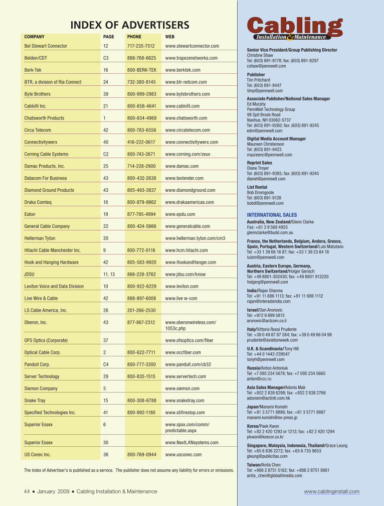
The index of Advertiser’s is published as a service. The publisher does not assume any liability for errors or omissions.
Senior Vice President/Group Publishing Director
Christine Shaw
Tel: (603) 891-9178; fax: (603) 891-9297
Publisher
Tim Pritchard
Tel: (603) 891-9447
Associate Publisher/National Sales Manager
Ed Murphy
PennWell Technology Group
98 Spit Brook Road
Nashua, NH 03062-5737
Tel: (603) 891-9260; fax: (603) 891-9245
Digital Media Account Manager
Maureen Christenson
Tel: (603) 891-9423
Reprint Sales
Diane Troyer
Tel: (603) 891-9385; fax: (603) 891-9245
List Rental
Bob Dromgoole
Tel: (603) 891-9128
INTERNATIONAL SALES
Australia, New Zealand/Glenn Clarke
Fax: +61 3 9 568 4955
France, the Netherlands, Belgium, Andora, Greece,
Spain, Portugal, Western Switzerland/Luis Matutano
Tel: +33 1 39 66 16 87; fax: +33 1 39 23 84 18
Austria, Eastern Europe, Germany,
Northern Switzerland/Holger Gerisch
Tel: +49 8801-302430; fax: +49 8801 913220
India/Rajan Sharma
Tel: +91 11 686 1113; fax: +91 11 686 1112
Israel/Dan Aronovic
Tel: +972 9 899 5813
Italy/Vittorio Rossi Prudente
Tel: +39 0 49 87 87 584; fax: +39 0 49 66 04 98
U.K. & Scandinavia/Tony Hill
Tel: +44 0 1442-239547
Russia/Anton Antoniuk
Tel: +7 095 234 5678; fax: +7 095 234 5665
Asia Sales Manager/Adonis Mak
Tel: +852 2 838 6298; fax: +852 2 838 2766
Japan/Manami Konishi
Tel: +81 3 5771 8886; fax: +81 3 5771 8887
Korea/Paek Kwon
Tel: +82 2 420 1293 or 1213; fax: +82 2 420 1294
Singapore, Malaysia, Indonesia, Thailand/Grace Leung
Tel: +65 6 836 2272; fax: +65 6 735 9653
Taiwan/Anita Chen
Tel: +886 2 8751 5162; fax: +886 2 8751 8861
44 ■ January 2009 ■ Cabling Installation & Maintenance www.cablinginstall.com
INDEX OF ADVERTISERSCOMPANY PAGE PHONE WEB
Bel Stewart Connector 12 717-235-7512 www.stewartconnector.com
Belden/CDT C3 888-768-6625 www.trapezenetworks.com
Berk-Tek 16 800-BERK-TEK www.berktek.com
BTR, a division of Ria Connect 24 732-380-8145 www.btr-netcom.com
Byte Brothers 39 800-999-2983 www.bytebrothers.com
Cablofi l Inc. 21 800-658-4641 www.cablofi l.com
Chatsworth Products 1 800-834-4969 www.chatsworth.com
Circa Telecom 42 800-783-6556 www.circatelecom.com
Connectivitywerx 40 416-222-0617 www.connectivitywerx.com
Corning Cable Systems C2 800-743-2671 www.corning.com/zeux
Damac Products, Inc. 25 714-228-2900 www.damac.com
Datacom For Business 43 800-432-2638 www.textender.com
Diamond Ground Products 43 805-493-3837 www.diamondground.com
Draka Comteq 18 800-879-9862 www.drakaamericas.com
Eaton 19 877-785-4994 www.epdu.com
General Cable Company 22 800-424-5666 www.generalcable.com
Hellerman Tyton 20 www.hellerman.tyton.com/cm3
Hitachi Cable Manchester Inc. 9 800-772-0116 www.hcm.hitachi.com
Hook and Hanging Hardware 42 805-583-9920 www.HookandHanger.com
JDSU 11, 13 866-228-3762 www.jdsu.com/know
Leviton Voice and Data Division 10 800-922-6229 www.leviton.com
Live Wire & Cable 42 888-897-6008 www.live w-com
LS Cable America, Inc. 26 201-266-2530
Oberon, Inc. 43 877-867-2312 www.oberonwireless.com/
1053c.php
OFS Optics (Corporate) 37 www.ofsoptics.com/fi ber
Optical Cable Corp. 2 800-622-7711 www.occfi ber.com
Panduit Corp. C4 800-777-3300 www.panduit.com/cb32
Server Technology 29 800-835-1515 www.servertech.com
Siemon Company 5 www.siemon.com
Snake Tray 15 800-308-6788 www.snaketray.com
Specifi ed Technologies Inc. 41 800-992-1180 www.stifi restop.com
Superior Essex 6 www.spsx.com/comm/
predictable.aspx
Superior Essex 30 www.NextLANsystems.com
US Conec Inc. 36 800-769-0944 www.usconec.com
| | | | | |Previous Page Contents Zoom in Zoom out Refer a Friend Search Issue Next Page BA
M SaGEFC7Installation MaintenanceC7
| | | | | |Previous Page Contents Zoom in Zoom out Refer a Friend Search Issue Next Page BA
M SaGEFC7Installation MaintenanceC7

©2009, Belden Inc.
Wired+Wireless=Belden
The addition of Trapeze Networks tothe Belden Total Enterprise Networks™family of signal transmission solutions nowallows you to naturally extend your wiredinfrastructure with a dynamic Wireless LAN.Trapeze Networks WLANs are unmatched forreliability, performance, manageability andsecurity – a perfectly matched extension toyour Belden structured cabling.
Unlike other companies, only Belden deliversa comprehensive, end-to-end solution offeringthe reliability and security on which your busi-ness depends. In addition to comprehensivewired and wireless network systems, ournew Total Enterprise Networks also providecabling networks for audio/video systems,alarm, security and many other managementapplications. With Belden, you can be sureyour wired and wireless infrastructures areproperly designed to work together foroptimal performance.
Trapeze Networks set a new standard forwireless reliability when it introduced NonStopWireless networking. Unlike others, Trapeze
Networks WLANs run continuously, evenwhen subjected to a variety of equipmentfailures, extreme traffic conditions or main-tenance that would cripple typical wirelessnetworks. Voice calls continue uninterrupted,sessions are securely maintained and usershave always-on access to mission-criticalnetwork services.
“The company’s NonStop Wireless ismore than a slogan. Its use of virtual controllercluster functionality is highly innovative.”– Stan Schatt, ABI Research
For more information, call us at 1.888.768.6625or visit www.trapezenetworks.com today.
Long known for itsindustry-leading structuredcabling system, Belden nowextends your wired networkwith Trapeze Networks®
NonStop Wireless™ for theAlways-on Enterprise.
See us at BICSI, Booth 519.
| | | | | |Previous Page Contents Zoom in Zoom out Refer a Friend Search Issue Next Page BA
M SaGEFC7Installation MaintenanceC7
| | | | | |Previous Page Contents Zoom in Zoom out Refer a Friend Search Issue Next Page BA
M SaGEFC7Installation MaintenanceC7

New information technologies continue to be adopted at remarkable rates. Highspeed data networks, IP Telephony, building systems, WiFi and Power overEthernet (PoE) devices are becoming more prevalent as building owners, developers,and tenants realize the benefits of structured cabling deployment. PANDUIT Connected Building Solutions leverage best-in-class network connectivityto extend the reach of the IP-based network to all building system devices to deliver:
■ Reduced capital and operational expenses – converged networks are physicallyavailable where and when needed, and provide more efficient moves, adds,and changes
■ Improved visibility of key operational data – converged networks allow forcontinuous monitoring of building systems, enhanced security, and increasedproductivity of maintenance and repair
■ Green, energy efficient buildings – converged networks enable EnhancedCommissioning and Energy Performance for a LEED rated building
As a leading technology developer and provider, the PANDUIT Solution isstrategically aligned with the Cisco Connected Real Estate (CCRE) initiative tomaximize the benefits of a converged networking environment.
PANDUIT Connected Building Solutionsconverge building system networks into acommon IT infrastructure for reduced costs andincreased efficiencies.
PANDUIT is a Global LeaderProviding Innovative End-To-EndNetwork Connectivity Solutionsthat Enable the Deployment of Technology.
■ Copper Cabling Systems■ Zone Cabling Systems■ Fiber Cabling Systems■ Network Management and
PoE Systems■ Outlets■ Raceway Systems■ Fiber Routing Systems■ Racks and Cable Management■ Network Grounding Systems■ Network Identification Systems■ Network Cable Ties and
Accessories
Visit us at www.panduit.com/cb32Contact Customer Service by email: [email protected]
or by phone: 800-777-3300 and reference ad #cb32
PANDUIT is a Solutions Enabler Partner for IP Communications within the Cisco Technology Developer Program.
| | | | | |Previous Page Contents Zoom in Zoom out Refer a Friend Search Issue Next Page BA
M SaGEFC7Installation MaintenanceC7
| | | | | |Previous Page Contents Zoom in Zoom out Refer a Friend Search Issue Next Page BA
M SaGEFC7Installation MaintenanceC7