cable replacement instructions - telpro inc. · pdf file30.01.2013 · - 6 - asme...
TRANSCRIPT

- 1 -
Questions? - Call Telpro Inc. Customer Service at 1-800-448-0822 or 701-775-0551
BEFORE instal l ing the components described in these instructions, determine the model of PANELLIFT® Brand Drywall Lift into which the components will be installed. THEN read and become famil iar with the complete Operator ’s Manual for that model
of PANELLIFT® Brand Drywall Lift.
The complete Operator’s Manual for the PANELLIFT® Brand Drywall Lift Model 138-2 and 125 is available at www.telproinc.com or call 701-775-0551 to receive a hard copy by mail.
BEFORE installing this component, thoroughly read this set of instructions, make sure you understand them, and only then follow the step-by-step directions.
FAILURE TO READ AND FOLLOW THESE INSTRUCTIONS could result in failure of the equipment. Failure of the equipment while the lift is raised can include a sudden and rapid lowering of the lift and
load possibly resulting in serious property damage and/or serious bodily injury.
WARNING
• Use and maintenance of the PANELLIFT® Drywall Lift shall be limited to authorized personnel who are trained in the proper techniques for its safe operation and maintenance and who are familiar with the various hazards of overhead material handling.
• DO NOT ATTEMPT TO USE YOUR PANELLIFT® Drywall Lift IF ANY PART IS MISSING, DAMAGED OR WORN. ORDER A REPLACEMENT PART IMMEDIATELY. Using a PANELLIFT®
Drywall Lift with missing, damaged or worn components can result in failure of the unit and possibly severe property damage and/or serious bodily injury.
• Inspect the Sheaves (Pulleys) and follow the procedure at the right to replace when worn. Sheave (Pulley) wear can occur where the cable rides and on the axle. Make sure to inspect both. Sheave can either be brass or aluminium. The sheave on the left is badly worn on both the axle and cable groove. Sheave on right is a new sheave.
• Use only factory authorized replacement parts. Installation of other parts can compromise the safe design of the PANELLIFT®
Drywall Lift and may cause failure of the unit possibly resulting in serious property damage and/or serious bodily injury.
“B” SectionSheave
Frame Sheave
Part No. 02-05 for PANELLIFT® Drywall Lift Model 138-2 and 125Part No. 186-03 for PANELLIFT® Drywall Lift Extension 186-00 and 186-12
CABLE REPLACEMENT INSTRUCTIONS
Inspect and replace sheaves (pulleys) before replacing the cable. There are 3 sheaves on the 138-2 Panellift®, one on the frame and two on the “B” telescoping section. Sheaves should be solid on their axle and not move up and down or back and forth. To replace, remove cotter keys and discard old axle and sheave. Replace with new sheave, axle and new cotter keys.
BE SURE that the cable is fed correctly over the roller sheaves according to the following instructions:
- 2 -
CABLE REPLACEMENT INSTRUCTIONS continued
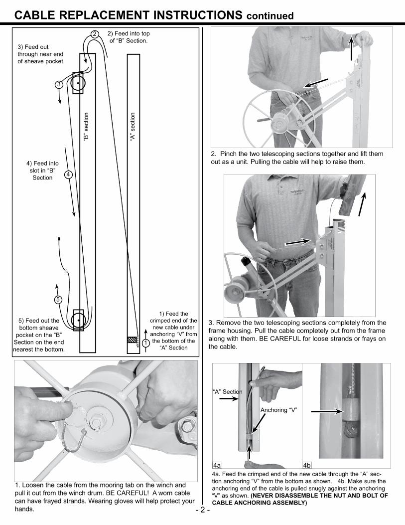
1) Feed the crimped end of the new cable under
anchoring “V” from the bottom of the
“A” Section
2) Feed into top of “B” Section.
3) Feed out through near end of sheave pocket
4) Feed into slot in “B” Section
5) Feed out the bottom sheave
pocket on the “B” Section on the end nearest the bottom.
3
2
4
5
1
“A” s
ectio
n
“B” s
ectio
n
4a. Feed the crimped end of the new cable through the “A” sec-tion anchoring “V” from the bottom as shown. 4b. Make sure the anchoring end of the cable is pulled snugly against the anchoring “V” as shown. (NEVER DISASSEMBLE THE NUT AND BOLT OF CABLE ANCHORING ASSEMBLY)
“A” Section
Anchoring “V”
4a 4b
1. Loosen the cable from the mooring tab on the winch and pull it out from the winch drum. BE CAREFUL! A worn cable can have frayed strands. Wearing gloves will help protect your hands.
2. Pinch the two telescoping sections together and lift them out as a unit. Pulling the cable will help to raise them.
3. Remove the two telescoping sections completely from the frame housing. Pull the cable completely out from the frame along with them. BE CAREFUL for loose strands or frays on the cable.

- 3 -
CABLE REPLACEMENT INSTRUCTIONS continued
8a. Reload and insert the cable installation tool into the BOTTOM end of the “B” section as shown.
8b. Repeat the process performed in steps 2 - 3: Insert the crimped end of the cable up into the end of the sheave pocket at the end nearest the bottom of the “B” section as traced by the dotted arrows. Twist the installation tool while holding the crimped end of the cable up into the sheave pocket. Pull the crimped end out completely to remove the slack.
YES-CorrectFeed out through this side of sheave pocket
7. Feed the crimped end of the cable down into the slot (a) of the “B” section and out the bottom end of the telescoping section (b) as shown. Pull the cable completely through to remove the slack.
X X
(a)(b)
DO NOTFeed into the
sheave pocket at these points!!
WARNINGThe cable MUST first pass down through the slot and out the bottom, then loop back in from the bottom of the “B” to feed through the sheave pocket exactly as shown in steps 4 - 5 in order to function properly. Failure to install the cable correctly as shown can cause wearing of the cable for which it is not designed which can result in failure of the cable. Failure of the cable while the lift is raised will result in a sudden and rapid lowering of the lift and the load possibly resulting in serious property damage and / or serious bodily injury.
NO!! - WRONG!!
DO NOT feed out through
this side of the sheave pocket!
X
6b. With a clock-wise motion like that of tightening a screw driver, twist the cable installation tool while holding the crimped end of the cable up into the sheave pocket. The cable will pop loose from the tool and pop up through the sheave pocket as shown in this cut away view.
5. Use the special tool provided to insert the crimped end of the cable into the TOP end of the “B” section as shown in this cut away view. If your “B” section is the factory original and not a replace-ment, the top is the painted end and the bottom has several inches of unfinished surface. If both ends of your “B” section are painted it is either a replacement or you are working on the “F” section of an extension 186-00. In either of these cases wear marks on the sec-tion should give you an indication of which end is the top.
“B” Section
There should not be more than 1” of cable extending beyond tool.
The cable MUST feed in from the top of the “B” exactly as shown in steps 2 - 3 in order to function properly. Failure to install the cable correctly as shown can cause wearing of the cable for which it is not designed which can result in failure of the cable. Failure of the cable while the lift is raised will result in a sudden and rapid lowering of the lift and the load possibly resulting in serious property damage and/or serious bodily injury.
WARNING
6a. Insert the crimped end of the cable into the sheave pocket at the end nearest the end of the “B” section as shown.
YES-Correct
Sheave Pocket
NO!!WRONG!!
X
- 4 -
CABLE REPLACEMENT INSTRUCTIONS continued
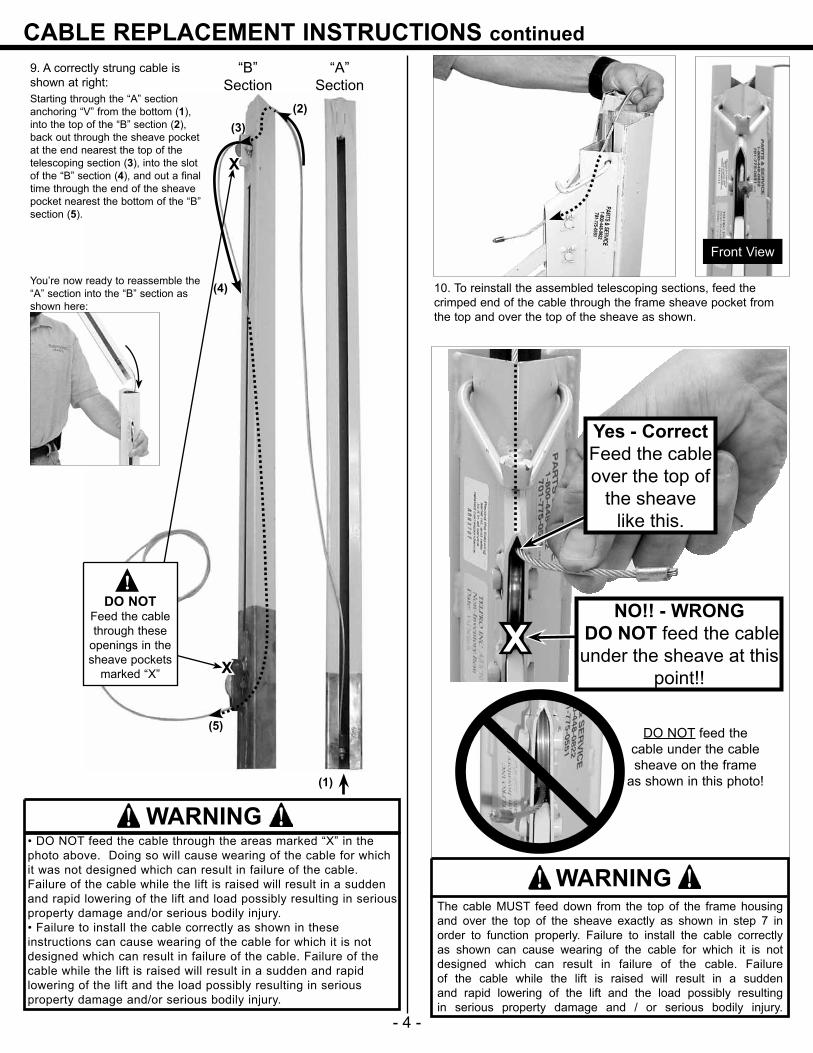
10. To reinstall the assembled telescoping sections, feed the crimped end of the cable through the frame sheave pocket from the top and over the top of the sheave as shown.
Front View
DO NOT feed the cable under the cable sheave on the frame
as shown in this photo!
X
Yes - CorrectFeed the cableover the top of
the sheavelike this.
NO!! - WRONG DO NOT feed the cable under the sheave at this
point!!
WARNINGThe cable MUST feed down from the top of the frame housing and over the top of the sheave exactly as shown in step 7 in order to function properly. Failure to install the cable correctly as shown can cause wearing of the cable for which it is not designed which can result in failure of the cable. Failure of the cable while the lift is raised will result in a sudden and rapid lowering of the lift and the load possibly resulting in serious property damage and / or serious bodily injury.
WARNING• DO NOT feed the cable through the areas marked “X” in the photo above. Doing so will cause wearing of the cable for which it was not designed which can result in failure of the cable. Failure of the cable while the lift is raised will result in a sudden and rapid lowering of the lift and load possibly resulting in serious property damage and/or serious bodily injury. • Failure to install the cable correctly as shown in these instructions can cause wearing of the cable for which it is not designed which can result in failure of the cable. Failure of the cable while the lift is raised will result in a sudden and rapid lowering of the lift and the load possibly resulting in serious property damage and/or serious bodily injury.
(1)
(2)(3)
(4)
(5)
“A” Section
“B” Section
DO NOTFeed the cable through these
openings in the sheave pockets
marked “X”
9. A correctly strung cable is shown at right: Starting through the “A” section anchoring “V” from the bottom (1), into the top of the “B” section (2), back out through the sheave pocket at the end nearest the top of the telescoping section (3), into the slot of the “B” section (4), and out a final time through the end of the sheave pocket nearest the bottom of the “B” section (5).
You’re now ready to reassemble the “A” section into the “B” section as shown here:
X
X

11. Pull the slack cable through the sheave pocket and slide the telescoping sections into the frame housing. As the telescoping sections lower into the frame, the slack cable will be drawn back up over the sheave.
13. Rotate the winch in the direction shown to take the slack out of the cable.
12. Feed the crimped end of the cable through the hole in the winch drum and secure it behind the mooring tab by hand pulling the cable snug as shown.
- 5 -

- 6 -
ASME Standards for wire rope (cable) inspection and replacementReprinted with permission from ASME B30.19 Cableways
The following is intended as a helpful guide to the general topic of inspection and replacement of wire rope (cable). It is not intended to be an exhaustive treatment of the topic.
Frequent inspection (at least daily) by a competent person and prompt replacement of any cable that shows any sign of wear is the responsibility of the owner and the operator of the PANELLIFT® Drywall Lift.
With reference to the chart below at 19-2.4.3(b)(6) the Panellift® Drywall Lift cable is a nominal 1/8” high tensile cable (rope).
(3) Care shall be taken when inspecting sections of rapid deterioration,
such as the following:(a) sections in contact with saddles, equalizer sheaves, or other sheaves,
including track cable sheaves, where rope travel is limited;(b) sections of the rope at or near terminal ends where corroded or broken
wires may develop.19-2.4.3 Rope Replacement(a) No precise rules can be given for determination of the exact time for
rope replacement, since many variable factors are involved. Once a rope reaches any one of the specified removal criteria, it may be allowed to operate to the end of the work shift, based on the judgment of a qualified person. The rope shall be replaced after that work shift, at the end of the day, or at the latest time prior to the equipment being used by the next work shift.
(b) Removal criteria for rope replacement shall be as follows: (1) In running ropes, six randomly distributed broken wires in one lay, or three broken wires in one strand in one lay. (2) One outer wire, broken at the contact point with the core of the rope,
that has worked its way out of the rope structure and protrudes and loops out from the rope structure. Additional inspection of this section is required.
(3) Wear of one-third the original diameter of outside individual wires. (4) Kinking, crushing, birdcaging, or any other damage resulting in
distortion of the rope structure. (5) Evidence of heat damage from any cause. (6) Reductions from nominal diameter greater than those shown below:
(7) In standing ropes, more than two broken wires in one lay in sections beyond end connections, or more than one broken wire at an end connection.
(c) Broken wire removal criteria cited in this Volume apply to wire rope operating on steel sheaves and drums. The user shall contact the sheave, drum, or cableway manufacturer, or a qualified person for broken wire removal criteria for wire ropes operating on sheaves and drums made of material other than steel.
(d) Replacement rope shall have a nominal strength rating at least equal to the original rope furnished or recommended by the cableway manufacturer or designer, or a qualified person. Any deviation from the original size, grade, or construction shall be specified by the rope manufacturer, the cableway manufacturer or designer, or a qualified person.
(e) Ropes Not in Regular Use. All rope that has been idle for a period of a month or more due to shutdown or storage of a cableway on which it is installed shall be given an inspection in accordance with para. 19-2.4.2(b) before it is placed in service. This inspection shall be for all types of deterioration and shall be performed by an appointed or authorized person.
(f) Inspection Records (1) Frequent inspection-no records required. (2) Periodic inspection - in order to establish data as a basis for judging
the proper time for replacement, a dated report of rope condition at each periodic inspection shall be kept on file. This report shall cover points of deterioration listed in para. 19-2.4.2(b)(2).
(g) A long-range inspection program should be established and should include records on examination of rope removed from service so a relationship can be established between visual observation and actual condition of the internal structure.
(00) General…
The use of cableways, cranes, derricks, hoists, hooks, jacks, and slings is subject to certain hazards that cannot be met by mechanical means but only by the exercise of intelligence, care, and common sense. It is therefore essential to have personnel involved in the use and operation of equipment who are competent, careful, physically and mentally qualified, and trained in the safe operation of the equipment and the handling of the loads. Serious hazards are overloading, dropping or slipping of the load caused by improper hitching or slinging, obstructing the free passage of the load, and using equipment for a purpose for which it was not intended or designed.…
Section 19-2.4: Rope Inspection, Replacement, and Maintenance19-2.4.1 General. Sheave diameters, drum diameters, and rope design
factors are limited because of cableway design configuration. Due to these parameters, inspection in accordance with para. 19-2.4.2 to detect deterioration and timely replacement in accordance with para. 19-2.4.3 are essential.
19-2.4.2 Inspection(a) Frequent Inspection (1) All running ropes in service should be visually inspected once each
working day. A visual inspection shall consist of observation of all rope that can reasonably be expected to be in use during the day’s operations. These visual observations should be concerned with discovering gross damage that may be an immediate hazard, such as listed below:
(a) distortion of the rope such as kinking, crushing, unstranding, birdcaging, main strand displacement, or core protrusion. Loss of rope diameter in a short rope length or unevenness of outer strands should provide evidence that the rope or ropes are to be replaced.
(b) general corrosion;(c) broken or cut strands;(d) number, distribution, and type of visible broken wires [see paras. 19-
2.4.3(b)(1), (2), and (7) for further guidance];(e) core failure in rotation-resistant ropes; when damage is suspected, the
rope shall either be removed from service or given an inspection as detailed in para. 19-2.4.2(b).
(2) Care shall be taken when inspecting sections of rapid deterioration, such as flange points, crossover points, and repetitive pickup points on drums.
(3) Care shall be taken when inspecting certain ropes, such as rotation-resistant ropes, because of their higher susceptibility to damage and increased deterioration when working on equipment with limited design parameters. The internal deterioration of rotation-resistant ropes may not be readily observable.
(b) Periodic Inspection (1) The inspection frequency shall be determined by a qualified person
and shall be based on such factors as expected rope life (determined by experience on the particular installation or similar installations), severity of environment, percentage of capacity lifts, frequency rates of operation, and exposure to shock loads. Inspections need not be at equal calendar intervals and should be more frequent as the rope approaches the end of its useful life. The inspection shall be made at least every 1000 hr of cableway operation or annually, whichever comes first.
(2) Periodic inspections shall be performed by an appointed or authorized person. This inspection shall cover the entire length of rope. Only the surface wires of the rope need be inspected. No attempt should be made to open the rope. Any deterioration resulting in appreciable loss of original strength, such as described below, shall be noted, and a determination shall be made as to whether further use of the rope would constitute a hazard:
(a) points listed in para. 19-2.4.2(a):(b) reduction of rope diameter below nominal diameter due to loss of core
support, corrosion, or wear of outside wires;(c) severely corroded or broken wires at end connections;(d) severely corroded, cracked, bent, worn, or improperly applied end
connections.
Max. Allowable Reduction From Rope Diam. Nominal Diam.
Up to 5/16 in. (8 mm) 1/64 in. (0.4 mm) Over 3/8 in. up to 1/2 in. (13 mm) 1/32 in. (0.8 mm) Over 9/16 in. up to 3/4 in. (19 mm) 3/64 in. (1.2 mm) Over 7/8 in. up to 1 1/8 in. (29 mm) 1/16 in. (1.6 mm) Over 1 1/4 in. up to 1 1/2’ in. (38 mm) 3/32 in. (2.4 mm)

- 7 -
This Page Intentionally Left Blank

Questions about assembly?
Can’t find a part?
Need some other help?
Call us:
1.800.448.0822 701.775.0551
We’ll get you set up!