cable data
DESCRIPTION
Technical data over heating cablesTRANSCRIPT
VärmeKabelTeknik Technical data – Heating cables
From
Technical data – Heating cables VärmeKabelTeknik 2
SERIES RESISTIVE HEATING CABLES The first heating cable that was produced was of a series resistive type. Today there are several types of series resistive heat‐ing cables available. These are manufactured in qualities from PVC to mineral insulated high‐temperature cable with rustless sheath. The biggest advantage with these is the possibility to obtain long element lengths, from only one point of connection.
In contrary to parallel resistive and self‐limiting heating cables which maximum length are limited by the voltage drop in the conductors, this is used as a heat emitting part in a series resistive cable. The heating conductor is manufactured of an alloy that gives required resistance per meter. By combining a required length with the available cable resistance's and supply voltages can advantages be obtained such as varying outputs, lengths from a couple of meter to lengths on 800‐1000m from one point of supply.
It is a disadvantage that the cable normally must be finished on the factory, which means you have to know the pipe lengths in advance to be able to pre order required lengths. (At long high‐temperature lengths where the heating conductor contains copper (CC‐cables) shall consideration be taken to the temperature coefficient of the heating conductor which influence the output of the length negatively).
For installations within the EX‐surface a number of supplementary safety devices is required, and exemption from the touched authorities.
Index Series resistive cables
Cable Page
TCPR with return-wire......................................... 3,4 TCPRH, with return-wire ..................................... 5,6 TCT, without return-wire ..................................... 7,8 TCTR, with return-wire ...................................... 9,10 TSF, without return-wire ...................................... 11 TSFR, with return-wire ......................................... 12 HCHH, mineral insulated ..................................... 13 VELOX SIP/PVC .................................................. 14 VELOX SIP/PFA .................................................. 15
VärmeKabelTeknik Technical data – Heating cables
3
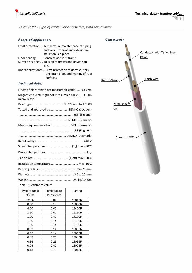
Velox TCPR ‐ Type of cable: Series resistive, with return‐wire
Range of application:
Frost protection: ... Temperature maintenance of piping and tanks. Interior and exterior in‐stallation in pipings.
Floor heating: ........ Concrete and joist frame. Surface heating: .... To keep footways and drives non‐
slip. Roof applications: .... Frost protection of down gutters
and drain pipes and melting of roof surfaces.
Technical data:
Electric field strength not measurable cable ..... < 3 V/m
Magnetic field strength not measurable cable ..... < 0.06 micro Tessla
Basic type ....................................... 90 CM acc. to IEC800
Tested and approved by ...................... SEMKO (Sweden)
................................................................... SETI (Finland)
............................................................. NEMKO (Norway)
Meets requirements from ...................... VDE (Germany)
..................................................................... BS (England)
.......................................................... DEMKO (Denmark)
Rated voltage ......................................................... 440 V
Sheath temperature. .............................. (Tm) max +90oC
Process temperature. ................................................. (Tp)
‐ Cable off............................................. (Tpoff) max +90oC
Installation temperature.................................. min ‐10oC
Bending radius ............................................... min 25 mm
Diameter ..................................................... 5.5 ± 0.5 mm
Weight ........................................................ 92 kg/1000m
Table 1: Resistance values
Type of cable (Ω/m)
Temperature Coefficience
Part.no
12.00 0.04 18812R8.00 0.15 18800R4.00 0.40 18400R2.90 0.40 18290R1.90 0.40 18190R1.30 0.14 18130R1.00 0.14 18100R0.82 0.14 18082R0.65 0.14 18065R0.45 0.25 18045R0.36 0.25 18036R0.25 0.40 18025R0.18 0.70 18018R
Construction
Conductor with Teflon insu‐lation
Return‐Wire Earth wire
Metallic scre‐en
Sheath inPVC

Technical data – Heating cables VärmeKabelTeknik 4
Velox TCPR ‐ Type of cable: Series resistive, with return‐wire
Sheath temperature
The sheath temperature (Tm) of the cable will vary de‐pending on the process (ambient) temperature (Tp), load (Q) and way of installation.
The sheath temperature is calculated as follows:
Tm = Q __ +Tp
Ua
Tm = Sheath temperature in oC
Tp = Process temperature in oC
Q = Load in W/m
Ua = Heat transfer coeff.
Example:
Velox TCPR mounted without dissipation of heat at an ambient temperature of 25oC, loaded with 20 W/m will have a sheath temperature of 65oC.
Installation in sand and concrete
Sand: max load 20 W/m cable.
Concrete: max load 25 W/m cable.
Sheath temperature: Diagram 1
Cable installed free in air or against heat conducting material (Ua = 0.45)
Read the diagram from right to left (see example (yellow line)
Dissipation of heat
The heat transfer coefficient (Ua) can be improved con‐siderably (3 to 10 times) by arranging some dissipation of heat, for instance by proating the cable with alumin‐ium tape.
For this kind of installation please consult Vär‐meKabelTeknik for assistance with the design and in‐stallation.
VärmeKabelTeknik Technical data – Heating cables
5
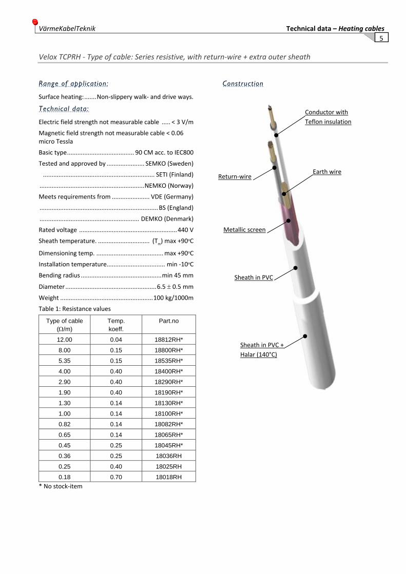
Velox TCPRH ‐ Type of cable: Series resistive, with return‐wire + extra outer sheath
Range of application:
Surface heating: ....... Non‐slippery walk‐ and drive ways.
Technical data:
Electric field strength not measurable cable ..... < 3 V/m
Magnetic field strength not measurable cable < 0.06 micro Tessla
Basic type ....................................... 90 CM acc. to IEC800
Tested and approved by ...................... SEMKO (Sweden)
................................................................. SETI (Finland)
............................................................. NEMKO (Norway)
Meets requirements from ...................... VDE (Germany)
..................................................................... BS (England)
.......................................................... DEMKO (Denmark)
Rated voltage ......................................................... 440 V
Sheath temperature. .............................. (Tm) max +90oC
Dimensioning temp. ....................................... max +90oC
Installation temperature.................................. min ‐10oC
Bending radius ............................................... min 45 mm
Diameter ..................................................... 6.5 ± 0.5 mm
Weight ...................................................... 100 kg/1000m
Table 1: Resistance values
Type of cable (Ω/m)
Temp. koeff.
Part.no
12.00 0.04 18812RH*
8.00 0.15 18800RH*
5.35 0.15 18535RH*
4.00 0.40 18400RH*
2.90 0.40 18290RH*
1.90 0.40 18190RH*
1.30 0.14 18130RH*
1.00 0.14 18100RH*
0.82 0.14 18082RH*
0.65 0.14 18065RH*
0.45 0.25 18045RH*
0.36 0.25 18036RH
0.25 0.40 18025RH
0.18 0.70 18018RH * No stock‐item
Construction
Conductor with Teflon insulation
Earth wire Return‐wire
Metallic screen
Sheath in PVC
Sheath in PVC + Halar (140°C)

Technical data – Heating cables VärmeKabelTeknik 6
Velox TCPRH ‐ Type of cable: Series resistive, with return‐wire + extra outer sheath
Sheath temperature
The sheath temperature (Tm) of the cable will vary de‐pending on the process (ambient) temperature (Tp), load (Q) and way of installation.
The sheath temperature is calculated as follows:
Tm = Q __ +Tp
Ua
Tm = Sheath temperature in oC
Tp = Process temperature in oC
Q = Load in W/m
Ua = Heat transfer coeff.
Example:
Velox TCP/R mounted without dissipation of heat with an ambient temperature of 25oC, loaded with 20 W/m will have a sheath temperature of 65oC.
Installation asphalt
Asphalt: max load 30 W/m cable.
Sheath temperature: Diagram 1 Cable installed free in air or against heat conducting material (Ua = 0.45)
Read the diagram from right to left (see example (yellow line)

VärmeKabelTeknik Technical data – Heating cables
7
Velox TCT ‐ Type of cable: Series resistive, without return‐wire
Range of application:
Temperature maintenance and heating of piping, tanks, vents etc in applications with high temperatures, large power requirements and aggressive environmental.
TCT can be installed at plants which are steam purified.
TCT has a sheath of corrosions toughened material (tef‐lon) and manages aggressive environmentals.
Technical data:
Basic type ..................................... NC acc. to SEN 242421
Tested and approved by ...................... SEMKO (Sweden)
................................................................. SETI (Finland)
................................................................ VDE (Germany)
Rated voltage ......................................................... 440 V
Resistance values ............................ acc. to Table 1 and 2
Process temperature. .................. (Tp) depending on load
‐ Cable off........................................... (Tpoff) max +220oC
Installation temperature.................................. min ‐30oC
Bending radius ............................................... min 15 mm
Diameter .............................................................. 4.1 mm
Weight ........................................................ 35 kg/1000m
Table 1: Resistance values
Type of cable (Ω/m)
Part.no
12,00 18812T
8.00 18800T
4.00 18400T
2,90 18290T
1,90 18190T
1.30 18130T
1.00 18100T
0.81 18082T
0.65 18065T
0.45 18045T
0.36 18036T
0.25 18025T
0.18 18018T
0.01 Cold-lead-in cable 1,5 18001T
Konstruktion
Resistance wire Cu, CuNi
Armourring – Braided Cu – 16 x 3 x 0.21mm
Sheath in Teflon FEP
Conductor insulation Teflon FEP

Technical data – Heating cables VärmeKabelTeknik 8
Velox TCT ‐ Type of cable: Series resistive, without return‐wire
Sheath temperature
The sheath temperature (Tm) of the cable will vary de‐pending on the process (ambient) temperature (Tp), load (Q) and way of installation.
The sheath temperature is calculated as follows:
Q Tm = ____ +Tp
Ua
Tm = Sheath temperature in oC
Tp = Process temperature in oC
Q = Load in W/m
Ua = Heat transfer coeff.
Example:
Velox TCT mounted without dissipation of heat at an ambient temperature of 100oC, output 30 W/m will have a sheath temperature of 146oC.
Dissipation of heat
The heat transfer coefficient (Ua) can be improved con‐siderably (3 to 10 times) by arranging some dissipation of heat, for instance by proating the cable with alumi‐nium tape. This will enable you to use the heating cable also at high process temperatures up to 200°C.
For this kind of installation please consult VärmeKabel‐Teknik for assis‐tance with the design and installation.
Sheath temperature: Diagram 1
Cable installed free in air or against heat conducting material (Ua = 0.65)
SHEATH TEMPERATURE TCT
0
50
100
150
200
250
300
350
400
0 10 20 30 40 50 60 70 80 90 100 110 120 130 140 150 160 170 180 190 200 210
Process temperature °C
Shea
th te
mpe
ratu
re °C
TCT 10WTCT 20WTCT 30WTCT 10W Med alu.tapeTCT 20W Med alu.tapeTCT 30W Med alu.tape
max temperature 220°C
VärmeKabelTeknik Technical data – Heating cables
9
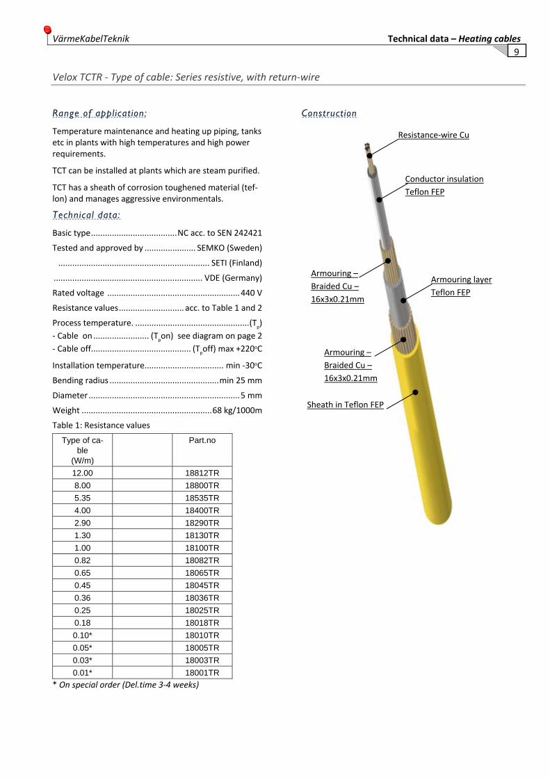
Velox TCTR ‐ Type of cable: Series resistive, with return‐wire
Range of application:
Temperature maintenance and heating up piping, tanks etc in plants with high temperatures and high power requirements.
TCT can be installed at plants which are steam purified.
TCT has a sheath of corrosion toughened material (tef‐lon) and manages aggressive environmentals.
Technical data:
Basic type ..................................... NC acc. to SEN 242421
Tested and approved by ...................... SEMKO (Sweden)
................................................................. SETI (Finland)
................................................................ VDE (Germany)
Rated voltage ......................................................... 440 V
Resistance values ............................ acc. to Table 1 and 2
Process temperature. ................................................. (Tp)‐ Cable on ........................ (Tpon) see diagram on page 2‐ Cable off........................................... (Tpoff) max +220oC
Installation temperature.................................. min ‐30oC
Bending radius ............................................... min 25 mm
Diameter ................................................................. 5 mm
Weight ........................................................ 68 kg/1000m
Table 1: Resistance values
Type of ca-ble
(W/m)
Part.no
12.00 18812TR 8.00 18800TR 5.35 18535TR 4.00 18400TR 2.90 18290TR 1.30 18130TR 1.00 18100TR 0.82 18082TR 0.65 18065TR 0.45 18045TR 0.36 18036TR 0.25 18025TR 0.18 18018TR 0.10* 18010TR 0.05* 18005TR 0.03* 18003TR 0.01* 18001TR
* On special order (Del.time 3‐4 weeks)
Construction
Resistance‐wire Cu
Conductor insulation Teflon FEP
Armouring layer Teflon FEP
Armouring – Braided Cu – 16x3x0.21mm
Armouring – Braided Cu – 16x3x0.21mm
Sheath in Teflon FEP
Technical data – Heating cables VärmeKabelTeknik 10
Velox TCTR ‐ Type of cable: Series resistive, with return‐wire
Sheath temperature
The sheath temperature (Tm) of the cable will vary de‐pending on the process (ambient) temperature (Tp), load (Q) and way of installation.
The sheath temperature is calculated as follows:
Q Tm = ____ +Tp
Ua
Tm = Sheath temperature in oC
Tp = Process temperature in oC
Q = Load in W/m
Ua = Heat transfer coeff.
Ua Installed without dDissipation of heat = 0,32 Ua With fitted Alu‐foil = 0.65 Ua With fitted Alu‐tape = 0.8
Example:
Velox TCTR mounted without dissipation of heat at an ambient temperature of 100oC, output 30 W/m will have a sheath temperature of 192oC.
Dissipation of heat
The heat transfer coefficient (Ua) can be improved con‐siderably (3 to 10 times) by arranging some dissipation of heat, for instance by proating the cable with alumi‐nium tape. This will enable you to use the heating cable also where high process temperatures are involved.
For this kind of installation please consult VärmeKabel‐Teknik for assis‐tance with the design and installation.
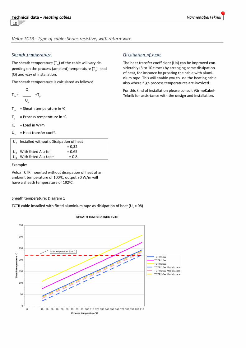
Sheath temperature: Diagram 1
TCTR cable installed with fitted aluminium tape as dissipation of heat (Ua = 08)
SHEATH TEMPERATURE TCTR
0
50
100
150
200
250
300
350
0 10 20 30 40 50 60 70 80 90 100 110 120 130 140 150 160 170 180 190 200 210
Process temperature °C
Shea
th te
mpe
ratu
re °C
TCTR 10WTCTR 20WTCTR 30WTCTR 10W Med alu.tapeTCTR 20W Med alu.tapeTCTR 30W Med alu.tape
Max temperature 220°C
VärmeKabelTeknik Technical data – Heating cables
11
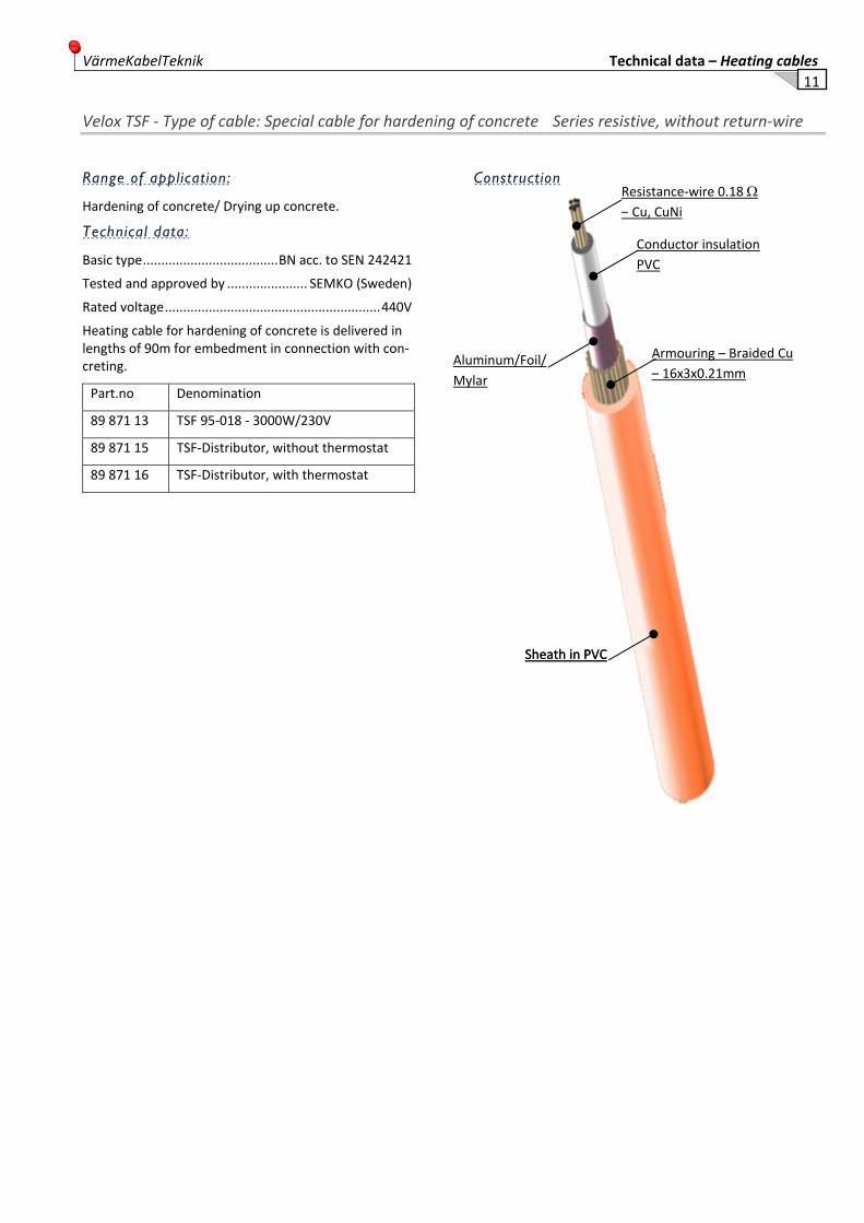
Velox TSF ‐ Type of cable: Special cable for hardening of concrete Series resistive, without return‐wire
Range of application:
Hardening of concrete/ Drying up concrete.
Technical data:
Basic type ..................................... BN acc. to SEN 242421
Tested and approved by ...................... SEMKO (Sweden)
Rated voltage ........................................................... 440V
Heating cable for hardening of concrete is delivered in lengths of 90m for embedment in connection with con‐creting.
Part.no Denomination
89 871 13 TSF 95‐018 ‐ 3000W/230V
89 871 15 TSF‐Distributor, without thermostat
89 871 16 TSF‐Distributor, with thermostat
Construction
Resistance‐wire 0.18 Ω – Cu, CuNi
Conductor insulation PVC
Armouring – Braided Cu – 16x3x0.21mm
Sheath in PVC Sheath in PVC
Aluminum/Foil/ Mylar
Technical data – Heating cables VärmeKabelTeknik 12
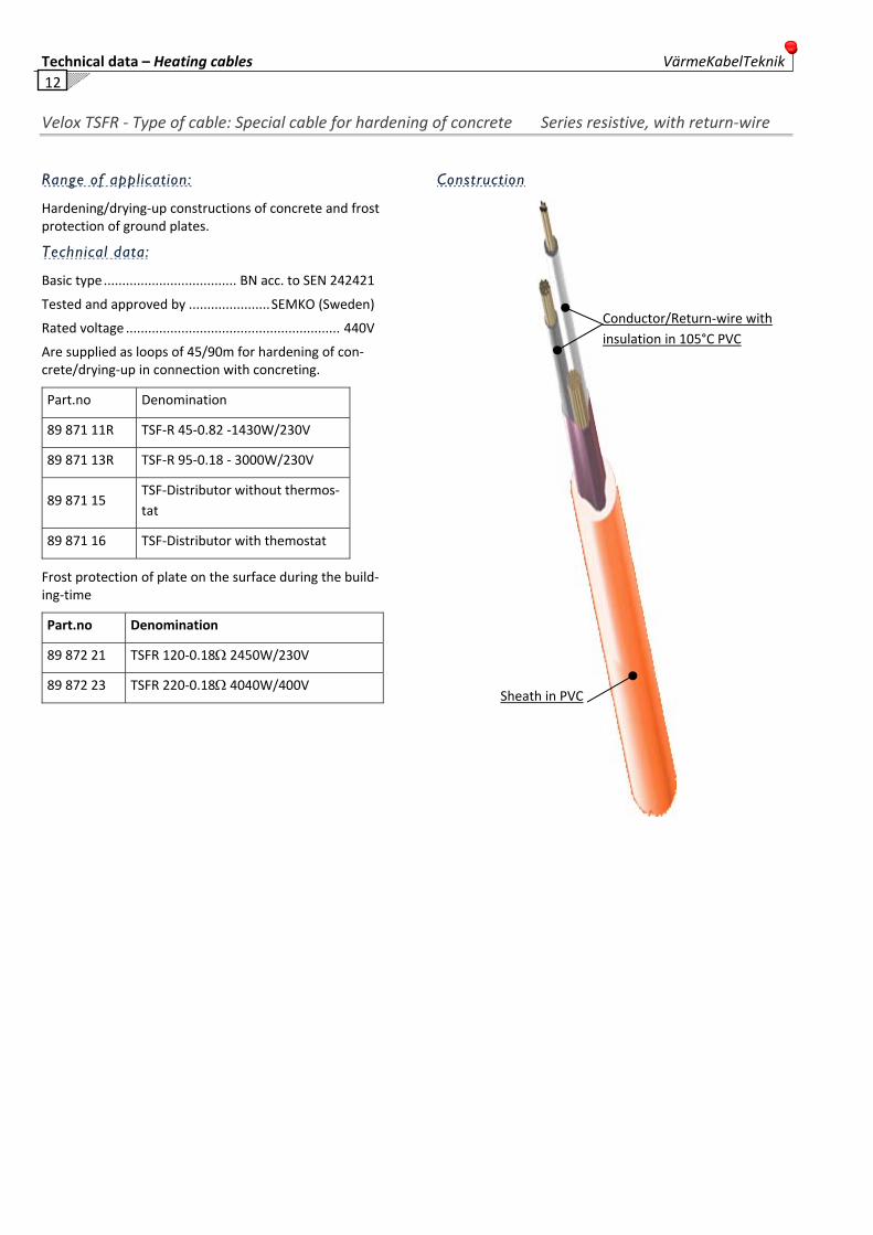
Velox TSFR ‐ Type of cable: Special cable for hardening of concrete Series resistive, with return‐wire
Range of application:
Hardening/drying‐up constructions of concrete and frost protection of ground plates.
Technical data:
Basic type .................................... BN acc. to SEN 242421
Tested and approved by ...................... SEMKO (Sweden)
Rated voltage .......................................................... 440V
Are supplied as loops of 45/90m for hardening of con‐crete/drying‐up in connection with concreting.
Part.no Denomination
89 871 11R TSF‐R 45‐0.82 ‐1430W/230V
89 871 13R TSF‐R 95‐0.18 ‐ 3000W/230V
89 871 15 TSF‐Distributor without thermos‐tat
89 871 16 TSF‐Distributor with themostat
Frost protection of plate on the surface during the build‐ing‐time
Part.no Denomination
89 872 21 TSFR 120‐0.18Ω 2450W/230V
89 872 23 TSFR 220‐0.18Ω 4040W/400V
Construction
Sheath in PVC
Conductor/Return‐wire with insulation in 105°C PVC
VärmeKabelTeknik Technical data – Heating cables
13
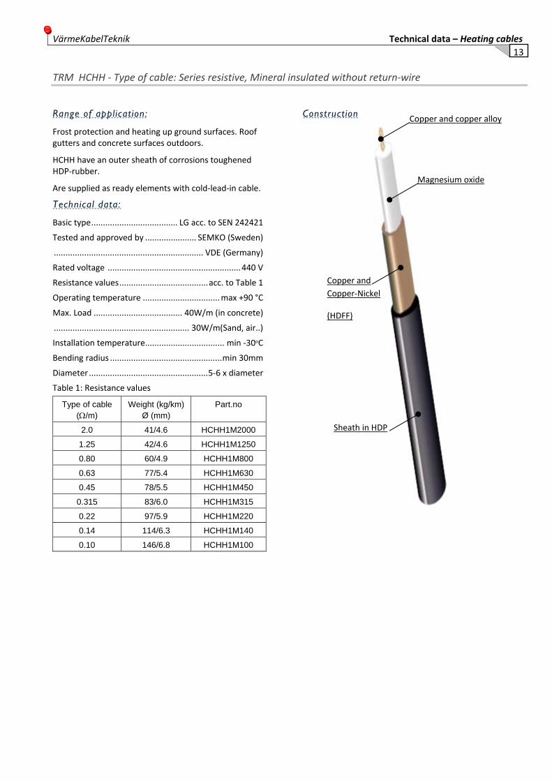
TRM HCHH ‐ Type of cable: Series resistive, Mineral insulated without return‐wire
Range of application:
Frost protection and heating up ground surfaces. Roof gutters and concrete surfaces outdoors.
HCHH have an outer sheath of corrosions toughened HDP‐rubber.
Are supplied as ready elements with cold‐lead‐in cable.
Technical data:
Basic type ..................................... LG acc. to SEN 242421
Tested and approved by ...................... SEMKO (Sweden)
................................................................ VDE (Germany)
Rated voltage ......................................................... 440 V
Resistance values ...................................... acc. to Table 1
Operating temperature ................................. max +90 °C
Max. Load ...................................... 40W/m (in concrete)
.......................................................... 30W/m(Sand, air..)
Installation temperature.................................. min ‐30oC
Bending radius ................................................ min 30mm
Diameter ................................................... 5‐6 x diameter
Table 1: Resistance values
Type of cable (Ω/m)
Weight (kg/km) Ø (mm)
Part.no
2.0 41/4.6 HCHH1M2000
1.25 42/4.6 HCHH1M1250
0.80 60/4.9 HCHH1M800
0.63 77/5.4 HCHH1M630
0.45 78/5.5 HCHH1M450
0.315 83/6.0 HCHH1M315
0.22 97/5.9 HCHH1M220
0.14 114/6.3 HCHH1M140
0.10 146/6.8 HCHH1M100
Construction
Sheath in HDP
Copper and Copper‐Nickel
(HDFF)
Magnesium oxide
Copper and copper alloy

Technical data – Heating cables VärmeKabelTeknik 14
VELOX SIP/PVC ‐ Type of cable: Series resistive, Double insulated, Class II
Range of application:
Switchpoint heating.
Velox SIP is a double insulated series resistive cable for connections up to 1000 VDC.
Technical data:
Basic type/Manufactured acc. to ................ VDE/IEC 800
Colour:.............................................. White outer sheath
Test voltage ........................................................... 3000V
Supply voltage ...................................... 750v/max 1000V
Output .............................................................. Ohms law
Max ambient temperature ...................................... 20°C
Max Exposure temperature ................................... 130°C
Lowest installation temp............................................. ‐10
Lowest bending radius ............................................. 6 x Ø
Diameter ..................................................... 4.5 / 5.0 mm ........................................................... depending on load
Weight ...................................... approx. 80‐90 kg/1000m
Part.no ............................................ SIP……….(+ Ω‐value)
Denomination: .................... Velox SIP + resistance‐value
SIP is manufactured with a sheath of PVC/Polyurethane
Table 1:
Type of cable Output (W/m)
Length max* (m)
VELOX SIP/PVC 50 W/m 50 W
* at 10% power loss.
Construction
Available resistance values
0.03 Ω 0.18 Ω 0.25 Ω 0.36 Ω 0.45 Ω 0.65 Ω 0.82 Ω 1.00 Ω
High temperature PVC/Polyurethane
High temperature Sili‐cone
Resistance‐wire

VärmeKabelTeknik Technical data – Heating cables
15
Velox SIP/PFA – Cable type: Series resistive, double insulated, Class II
Range of application:
Switchpoint heating and power rail heating.
Velox SIP is a double insulated series resistive heat‐ing cable for connections up to 1000 VDC.
Technical data:
Manufacturing std/Basic type .................... VDE/IEC 800
Colour: .............................................. White outer sheath
Test voltage .......................................................... 3000V
Supply voltage ...................................... 750v/max 1000V
Output ............................................................. Ohms law
Max ambient temperature. ...................................... 20°C
Max exposure temperature ....................................130°C
Lowest installation temp. ........................................... ‐10
Lowest bending radius ............................................. 6 x Ø
Diameter ..................................................... 4.5 / 5.0 mm ........................................................... depending on load
Weight ..................................... approx. 80‐90 kg/1000m
Part.no ........................................ SIP/PFA…….(+ Ω‐value)
Denomination: .................... Velox SIP + resistance‐value
SIP/PFA are manufactured with a sheath of PFA.
Table 1:
Type of cable Output (W/m)
Length max* (m)
VELOX SIP/PVC 80 W/m Ohms law
* at 10% power loss.
Construction
High temperature PFA
High temperature Sili‐cone
Resistance‐wire

Technical data – Heating cables VärmeKabelTeknik 16
SELF‐LIMITING HEATING CABLES Self‐limiting cables can be bought in running metre for make‐up on the site. The cable has a varying output depending on the ambient temperature, which guard against overheating even if the cable crosses itself. This also allows installation in Ex‐surfaces (all Värmekabeltekniks self‐limiting cable types are Ex‐rated).
The self‐limiting cable have a unique capacity in proportion to the sheath temperature of the cable, reduce the emitted out‐put. These cables are often mentioned as self‐regulated cables but this is a wrong denomination, as a required temperature not can be guaranteed without temperature control.
On the other hand, the cables make it possible to give an even temperature on a pipe even if the ambient temperature varies along piping.
Värmekabeltekniks self‐limiting cables are approved within Ex‐surfaces when the cables have a stated T‐rate, i.e. a maximum temperature that the cable reach. The T‐rates varies for different output/m.
The self‐limiting cables are built up round a semi‐conductive bed embedded in the outer edges. The bed between the con‐ductors has a capacity to lead current, the conducting capacity is in proportion to the temperature. At rising temperature the conducting capacity decreases, overheating is prevented. At sinking temperature, the current increases and the increasing heat requirement is satisfied.
- RSL Frost protection cables, have a primary insulation and an outer sheath of thermo‐plastic rubber (CR) or teflon (CT).
‐ RSM cables for keeping warm and heating up to 120°C, has an insulation and outer sheath of Teflon.
‐ RSH cables for keeping warm and heating up to 190°C, has an insulation and outer sheath of teflon.
The emitted outputs of the self‐limiting cables are depending on the ambient temperature and the method of installation, a good dissipation of heat increase the emitted output. (Aluminium tape that covers all the length of the cable and is attached against the pipe, cool down the side of the cable, which borders against the insulation and thereby, emitted output with 30‐50%).
All self‐limiting cables have a starting current which is higher than the operating current. This must be taken into consid‐eration when designing circuit‐/connection lengths, (see data sheet).
Index Self‐limiting cables
Cable Page
BTL‐10 .................................................................. 17 BTL Floorheat ....................................................... 18 BTL‐N ............................................................... 19‐20 SAFE‐T .................................................................. 21 RSL ................................................................ 22‐23 RSM ................................................................ 24‐25 RSH ................................................................ 26‐27 AQUA‐55 ......................................................... 28‐29 AQUA‐60 ......................................................... 30‐31 VELOX ORIGO30‐110/120 .................................... 32 VELOX ORIGO30‐230/240 .................................... 33 VELOX ORIGO30‐DC ............................................. 34
VärmeKabelTeknik Technical data – Heating cables
17
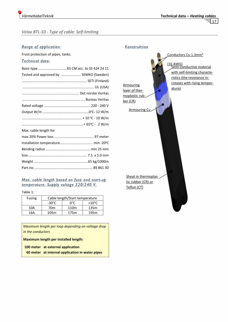
Velox BTL‐10 ‐ Type of cable: Self‐limiting
Range of application:
Frost protection of pipes, tanks.
Technical data:
Basic type .............................. 65 CM acc. to SS 424 24 11
Tested and approved by ..................... SEMKO (Sweden)
................................................................... SETI (Finland)
........................................................................... UL (USA)
........................................................... Det norske Veritas
................................................................. Bureau Veritas
Rated voltage ................................................ 220 ‐ 240 V
Output W/m ................................................00C‐ 12 W/m
.............................................................. + 10 0C ‐ 10 W/m
............................................................... + 650C ‐ 2 W/m
Max. cable length for
max 20% Power loss ......................................... 97 meter
Installation temperature.................................. min ‐200C
Bending radius ............................................... min 25 mm
Size ............................................................. 7.5 x 5.0 mm
Weight ........................................................ 65 kg/1000m
Part.no. ............................................................ 89 861 30
Max. cable length based on fuse and start-up temperature. Supply voltage 220/240 V.
Table 1:
Fusing Cable length/Start temperature‐30°C 0°C +10°C
10A 70m 110m 135m16A 105m 175m 195m
Maximum length per loop depending on voltage drop in the conductors
Maximum length per installed length:
100 meter at external application 60 meter at internal application in water pipes
Konstruktion
Conductors Cu 1.3mm²
(16 AWG) Semi‐conductive material with self‐limiting characte‐ristics (the resistance in‐creases with rising temper‐ature)
Armouring layer of ther‐moplastic rub‐ber (CR)
Armouring Cu
Sheat in thermoplas‐tic rubber (CR) or Teflon (CT)

Technical data – Heating cables VärmeKabelTeknik 18
Velox BTL Floorheat ‐ Type of cable: Self‐limiting
Range of application:
Floor heating.
Technical data
Basic type .............................. 65 CM acc. to SS 424 24 11
Tested and approved by ...................... SEMKO (Sweden)
.................................................................. SETI (Finland)
........................................................................... UL (USA)
........................................................... Det Norske Veritas
................................................................. Bureau Veritas
Rated voltage ................................................ 220 ‐ 240 V
Output W/m ........................................................ + 200C ≈ ..................................................................... 18‐20 W/m
Max. cable length for
max 20% Power loss ......................................... 62 meter
Installation temperature.. ................................ min ‐150C
Bending radius .............................................. min 25 mm
Size ............................................................. 7.5 x 5.0 mm
Weight ........................................................ 65 kg/1000m
Part.no. ............................................................ 89 861 50
Max. cable length based on fuse and start-up temperature. Supply voltage 220/240 V.
Table 1
Fusing Cable length/Start temperature
‐20°C 0°C +10°C +20°C
10A 37m 44m 72m 79m
16A 60m 77m 127m 140m
Construction
Conductors
Semi‐conductive material with self‐limiting characte‐ristics (the resistance in‐creases with rising temper‐ature)
Armouring layer
Armouring 1.5mm²
Sheath in TPE

VärmeKabelTeknik Technical data – Heating cables
19
Velox BTL10 N ‐ Type of cable: Self‐limiting
Range of application:
Frost protection of pipes, tanks below +65oC.
Technical data:
Basic type ............................................................... 65 CM ......................................................... acc. to SS 424 24 11
Tested and approved by ...................... SEMKO (Sweden)
.................................................................. SETI (Finland)
Rated voltage ................................................. 220 ‐ 240 V
Process temp. ............................................................. (Tp)
‐ Cable on .............................................(Tpon) max +65oC
‐ Cable off............................................. (Tpoff) max +85oC
Installation temperature.................................. min ‐20oC
Bending radius ............................................... min 15 mm
Size ........................................................... 11.1 x 4.8 mm
Weight ...................................................... 118 kg/1000m
BTL N is manufactured with a sheath of teflon (CT).
Table 1
Type of cable
Output +10°C (W/m)
Length max* (m)
BTL-N 10 211
* at 10% power loss
Construction
Conductors
Semi‐conductive material with self‐limiting characte‐ristics (the resistance in‐creases with rising temper‐ature)
Armouring layer of thermoplastic rubber (CR)
Armouring 1.5mm²
Sheath in Teflon (CT)

Technical data – Heating cables VärmeKabelTeknik 20
Velox BTL10 N ‐ Type of cable: Self‐limiting
Max. cable lenghts based on fuse and start/up temperature. Supply voltage 220/240 V.
Fuses loaded with 0.8 x nominal current.
Table 2: 10 Ampere
Type of cable
Max cable length/Start temperature
-20°C 0°C +10°C +20°C
BTL-N 62m 73m 80m 89m
Table 4: 20 Ampere
Type of cable
Max. cable length/Start temperature
-20°C 0°C +10°C +20°C
BTL-N 123m 145m 160m 178m
Table 3: 16 Ampere
Type of cable
Max. Cable length/Start temperature
-20°C 0°C +10°C +20°C
BTL-N 98m 116m 128m 142m
0
5
10
15
20
25
30
35
40
-20 -10 0 10 20 30 40 50 60 70
Avgi
ven
effe
kt W
Rör temperatur °C
VELOX BTL
BTL-10
FLOOR HEAT
SAFE-T
VärmeKabelTeknik Technical data – Heating cables
21
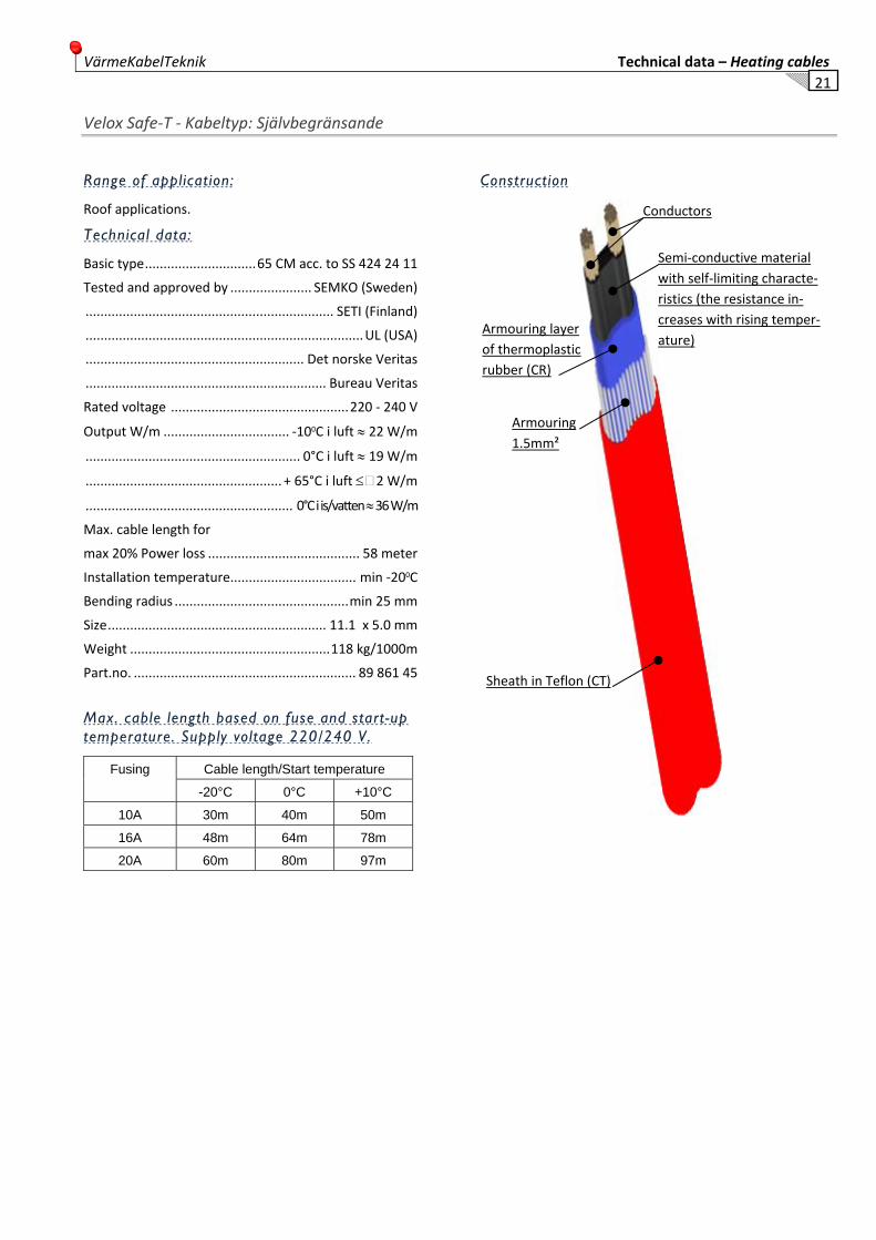
Velox Safe‐T ‐ Kabeltyp: Självbegränsande
Range of application:
Roof applications.
Technical data:
Basic type .............................. 65 CM acc. to SS 424 24 11
Tested and approved by ...................... SEMKO (Sweden)
................................................................... SETI (Finland)
........................................................................... UL (USA)
........................................................... Det norske Veritas
................................................................. Bureau Veritas
Rated voltage ................................................ 220 ‐ 240 V
Output W/m .................................. ‐100C i luft ≈ 22 W/m
.......................................................... 0°C i luft ≈ 19 W/m
..................................................... + 65°C i luft ≤ 2 W/m
........................................................ 0°C i is/vatten ≈ 36 W/m
Max. cable length for
max 20% Power loss ......................................... 58 meter
Installation temperature.................................. min ‐200C
Bending radius ............................................... min 25 mm
Size ........................................................... 11.1 x 5.0 mm
Weight ...................................................... 118 kg/1000m
Part.no. ............................................................ 89 861 45
Max. cable length based on fuse and start-up temperature. Supply voltage 220/240 V.
Fusing Cable length/Start temperature
-20°C 0°C +10°C
10A 30m 40m 50m
16A 48m 64m 78m
20A 60m 80m 97m
Construction
Conductors
Semi‐conductive material with self‐limiting characte‐ristics (the resistance in‐creases with rising temper‐ature)
Armouring layer of thermoplastic rubber (CR)
Armouring 1.5mm²
Sheath in Teflon (CT)

Technical data – Heating cables VärmeKabelTeknik 22
Velox TTS super‐ Type of cable: Self‐limiting
• Self‐regulating
• 7 power output ranges
• Cut to length
Range of application:
Velox Super is a construction and industrial grade self‐regulating heating tape that may be used for frost pro‐tection, or temperature maintenance of pipework and vessels.
Function:
Self‐regulating heating cables consist of two parallel buswires, embedded semi‐conductive self‐regulating matrix. This means that the heating cable automatically responds to changes in ambient conditions.
With increase in temperature, the synthetic material expands by molecular force, and the connections be‐tween the carbon particles diminish, reducing the load. Conversely, as the temperature decreases, so the load increases as the connections between the carbon parti‐cles increases accordingly.
Thus, the heating power varies according to the tem‐perature surface of the surface the heating cable is applied to.
Self‐regulating heating cables will not overheat or burn‐out – even when overlapped.
Technical data:
Maximum exposure temperature (unpowered) .. 200°C** maximal 1000 hours exposure time
Maximum operating temperature (powered) ....... 120°C
Nominal voltage ............................................. 220 ‐ 240 V ............................................... (120 V available on order)
Minimum bending radius. .....................................25 mm
Minimum installation temperature ........................ ‐30oC
Maximum resistance of braid .................. 18.2 Ohms/km
T‐rating. ........................................................................ T3
Construction
1.25mm² Buswires
Semi‐conductive material with self‐limiting characteris‐tics (the resistance increases with ris‐ing temperature)
Insulation
Earth braiding tinned copper
Sheath in fluoropo‐lymer

VärmeKabelTeknik Technical data – Heating cables
23
Velox TTS super ‐ Type of cable: Self‐limiting
Part.no Power output on insulated metal pipes at 10°C
Maximum ambient ener‐gised
Permissabgle temperature de‐energised
Earth Braid Description
Nominal di‐mensions
Nominal weight
(W/m) (°C) (°C) (mm) Kg/100m10TTS‐2‐B 10 120 200 TC 9.5 x 4.0 1210TTS‐2‐BOT 10 120 200 TC 10.5 x 5.0 1215TTS‐2‐B 15 120 200 TC 9.5 x 4.0 1215TTS‐2‐BOT 15 120 200 TC 10.5 x 5.0 1220TTS‐2‐B 20 120 200 TC 9.5 x 4.0 1220TTS‐2‐BOT 20 120 200 TC 10.5 x 5.0 1225TTS‐2‐B 25 120 200 TC 9.5 x 4.0 1225TTS‐2‐BOT 25 120 200 TC 10.5 x 5.0 1230TTS‐2‐B 30 120 200 TC 9.5 x 4.0 1230TTS‐2‐BOT 30 120 200 TC 10.5 x 5.0 1245TTS‐2‐B 45 120 200 TC 9.5 x 4.0 1245TTS‐2‐BOT 45 120 200 TC 10.5 x 5.0 1260TTS‐2‐B 60 120 200 TC 9.5 x 4.0 1260TTS‐2‐BOT 60 120 200 TC 10.5 x 5.0 12
TC = Tinned copper ‐ B = Tinned copper braid ‐ BOT = Braid and fluoropolymer o verjacket Temperature/Loading diagram TTS
TTS exposure up to 200°C (maximal 1000 hours exposure time)
Start‐up temp 230V 120V16A 20A 30A 16A 20A 30A
10 TTS +10‐25
200175
235235
100 89
120120
15 TTS +10‐25
165117
189152
189
80 56
9575 95
20 TTS +10‐25
135100
160130
160
67 50
8065 80
25 TTS +10‐25
12088
140120
140
60 44
6959 69
30 TTS +10‐25
8569
11492
114
44 35
5845 58
45 TTS +10‐25
7049
8266
82
35 24
4133 41
60 TTS +10‐25
5038
6452
64
25 20
3225 32
Maximum recommended length of heating circuit at 230VAC using Type‐C circuit breakers
Product ordering information:
Power output + TTS‐Voltage‐(Overjacket)
Example: 60 W/m@10°C with tinned copper braiding and fluoropolymer jacket (230V):
60 TTS‐2‐BOT
Example: 15 W/m@10°C with only insulation (120V):
15 TTS‐1
B: tinned copper braid BOT: Braid and fluoropolymer overjacket.

Technical data – Heating cables VärmeKabelTeknik 24
Velox TTR Regular ‐ Type of cable: Self‐limiting
• Self‐regulating
• 4 power output ranges
• Proprietary bonded jacket
Range of application:
Velox Regulator is a construction and industrial grade self‐regulating heating cable that may be used for frost protection, or low temperature maintenance of pipe‐work and vessels.
Function:
Self‐regulating heating cables consist of two parallel buswires, embedded semi‐conductive self‐regulating matrix. This means that the heating cable automatically responds to changes in ambient conditions.
With increase in temperature, the synthetic material expands by molecular force, and the connections be‐tween the carbon particles diminish, reducing the load. Conversely, as the temperature decreases, so the load increases as the connections between the carbon parti‐cles increases accordingly.
Thus, the heating power varies according to the tem‐perature surface of the surface the heating cable is applied to.
Self‐regulating heating cables will not overheat or burn‐out – even when overlapped.
Technical data:
Maximum exposure temperature (unpowered) .... 85°C** maximal 1000 hours exposure time
Maximum operating temperature (powered) ......... 65°C
Nominal voltage ...................................................... 230 V ............................................... (120 V available on order)
Minimum bending radius. .....................................25 mm
Minimum installation temperature ........................ ‐30oC
Maximum resistance of braid .................. 18.2 Ohms/km
T‐rating.10,15,25 W/m ................................................ T6
T‐rating 10,15,25 W/m ................................................. T5
Construction
1.25mm² Buswires
Semi‐conductive material with self‐limiting characteris‐tics (the resistance increases with ris‐ing temperature)
Insulation
Earth braiding tinned copper
Sheath in fluoropo‐lymer or thermoplas‐ic

VärmeKabelTeknik Technical data – Heating cables
25
Velox TTR Regular‐ Type of cable: Self‐limiting
Part.no Power output on insulated metal pipes at 10°C
Maximum ambient ener‐gised
Permissabgle temperature de‐energised
Earth Braid Description
Nominal di‐mensions
Nominal weight
(W/m) (°C) (°C) (mm) Kg/100m10TTR‐2‐BO 10 65 85 TC 11.5 x 5.5 1210TTR‐2‐BOT 10 65 85 TC 11.5 x 5.5 1215TTR‐2‐BO 15 65 85 TC 11.5 x 5.5 1215TTR‐2‐BOT 15 65 85 TC 11.5 x 5.5 1225TTR‐2‐BO 25 65 85 TC 11.5 x 5.5 1225TTR‐2‐BOT 25 65 85 TC 11.5 x 5.5 1233TTR‐2‐BO 33 65 85 TC 11.5 x 5.5 1233TTR‐2‐BOT 33 65 85 TC 11.5 x 5.5 12
TC = Tinned copper ‐ BO = Braid and thermoplastic overjacket ‐ BOT = Braid and fluoropolymer overjacket Temperature/Loading diagram TTR
Surface temperature on insulated metal pipes (°C)
TTR exposure up to 85°C
Start‐up temp 230V 120V16A 20A 30A 16A 20A 30A
10 TTR +10‐15 ‐25
205140123
186 165
195 195
95 69 60
90 81
95 95
15 TTR +10‐25 ‐25
14593 82
162125 111
160 160
67 45 40
8061 54
80 80
25 TTR +10‐15 ‐25
8860 50
11775 70
126 117 105
43 27 27
5833 33
6351 51
33 TTR +10‐15 ‐25
7050 45
9065 58
108 95 85
33 25 22
4533 30
5453 43
Maximum recommended length of heating circuit at 230VAC using Type‐C circuit breakers
Product ordering information:
Power output + TTR‐Voltage‐(Overjacket)
Example: 33 W/m@10°C with tinned copper braiding and fluoropolymer jacket (230V):
33 TTR‐2‐BOT
Example: 15 W/m@10°C with only insulation (120V):
15 TTR‐1
B: tinned copper braid BO: Braid and thermoplastic overjacet BOT: Braid and fluoropolymer overjacket.

Technical data – Heating cables VärmeKabelTeknik 26
Velox AQUA – Type of cable: Self‐limiting
Range of application:
Frost protection and temperature maintenance of hot‐water pipes up to 55oC.
Cable data:
Basic type .............................. 65 CM acc. to SS 424 24 11
Approved, tested by ............................. SEMKO (Sweden)
.................................................................. SETI (Finland)
........................................................................... UL (USA)
........................................................... Det Norske Veritas
................................................................. Bureau Veritas
Connection voltage ........................................ 220 ‐ 240 V
Process temp.............................................................. (Tp)
‐ cable on.............................................. (Tpon) max +65oC
‐ cable off ............................................. (Tpoff) max +85oC
Installation temperature .................................. min ‐20oC
Bending radius .............................................. min 15 mm
Dimension ................................................ 11.1 x 4.8 mm
Weight ...................................................... 118 kg/1000m
The AQUA‐cable is manufactured with a sheath of ther‐mo‐plastic rubber (CR) or tefon (CT).
Table 1
Type of cable
Power +10°C (W/m)
Length max* (m)
T-Class Part.no
AQUA 55 26 128 T5 8986190
AQUA 60 33 110 T5 89861906 * vid 10% effektbortfall
Construction
Conductors Cu 1.3mm² (AWG‐16)
Semi‐conductive material with self‐limiting characte‐ristics (the resistance in‐creases with rising temper‐ature)
Armouring layer of thermoplastic rubber (CR)
Armouring
Cu
Sheath in thermo‐plastic rubber (CR) or Teflon (CT)

VärmeKabelTeknik Technical data – Heating cables
27
Velox AQUA – Type of cable: Self‐limiting
Max. cable lenghts based on fuse and start/up temperature. Supply voltage 220/240 V.
Fuses loaded with 0.8 x nominal current.
Table 2: 10 Ampere
Type of cable
Max. Cable length/Start temperature
-20°C 0°C +10°C +20°C
AQUA 55 19m 25m 31m 37m
AQUA 60 16m 18m 20m 21m
Table 4: 20 Ampere
Type of cable
Max. Cable length/Start temperature
-20°C 0°C +10°C +20°C
AQUA 55 38m 50m 62m 74m
AQUA 60 32m 37m 41m 43m
Table 3: 16 Ampere
Type of cable
Max. Cable length/Start temperature
-20°C 0°C +10°C +20°C
AQUA 55 30m 41m 49m 59m
AQUA 60 25m 29m 32m 34m

Technical data – Heating cables VärmeKabelTeknik 28
Velox switchpoint heating element ORIGO30‐110/120 ‐ Type of cable: Self‐limiting
Range of application:
Switchpoint heating at railways, tramways, sub‐ways.
Technical data:
Basic type .............................................................. Klass II
Manufactured acc. to ................................... VDE, IEC800
Cable class .......................................... Double insulated*
Test voltage ..................................................... 1500 V DC
Supply voltage ................................................. 110 /120V
Colour:................................................ Black outer sheath
Operating temperature ................. max. +120°C / +150°C
Exposure temperature .................. max. +160°C / +250°C
Installation temperature ................................ min – 20°C
Bending radius .............................................. min 40 mm
Dimension ................................................. 11.5 x 6.5 mm
Weight ............................................................. 0.15 kg/m
Part.no: ................................................................. VX501
Denomination .......................... Velox ORIGO30‐110/120
Approved by Network Rail – Certification no. PA05100458
Velox ORIGO30‐110/120 is manufactured with a sheath of PFA.
Table 1:
Type of cable Output (W/m)
Length max* (m)
VELOX ORIGO30 110/120 25
* at 10% power loss.
Construction
* Double insulated cable with each insulation layer thickness according to IEC:1995. R.M.S. 450/750 V. Min. requirement 0.60mm/layer.
Semi‐conductive ma‐terial with self‐limiting characteristics (the resistance increases with rising temperature)
Conductor2 x 1.3mm²
Insulation and outer sheath of fluorpolymer
VärmeKabelTeknik Technical data – Heating cables
29
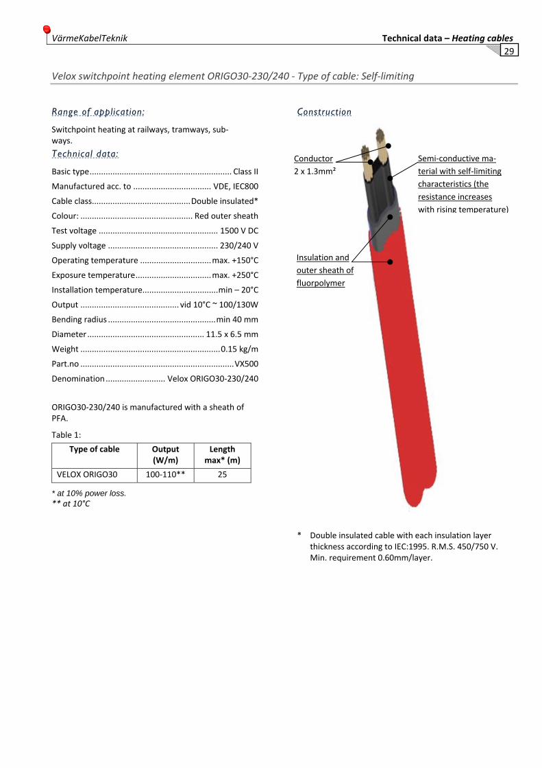
Velox switchpoint heating element ORIGO30‐230/240 ‐ Type of cable: Self‐limiting
Range of application:
Switchpoint heating at railways, tramways, sub‐ways.
Technical data:
Basic type .............................................................. Class II
Manufactured acc. to .................................. VDE, IEC800
Cable class ........................................... Double insulated*
Colour: ................................................. Red outer sheath
Test voltage .................................................... 1500 V DC
Supply voltage ................................................ 230/240 V
Operating temperature ............................... max. +150°C
Exposure temperature ................................. max. +250°C
Installation temperature................................. min – 20°C
Output ........................................... vid 10°C ~ 100/130W
Bending radius ............................................... min 40 mm
Diameter ................................................... 11.5 x 6.5 mm
Weight ............................................................. 0.15 kg/m
Part.no ................................................................... VX500
Denomination .......................... Velox ORIGO30‐230/240
ORIGO30‐230/240 is manufactured with a sheath of PFA.
Table 1:
Type of cable Output (W/m)
Lengthmax* (m)
VELOX ORIGO30 100‐110** 25
* at 10% power loss. ** at 10°C
Construction
* Double insulated cable with each insulation layer
thickness according to IEC:1995. R.M.S. 450/750 V. Min. requirement 0.60mm/layer.
Semi‐conductive ma‐terial with self‐limiting characteristics (the resistance increases with rising temperature)
Conductor2 x 1.3mm²
Insulation and outer sheath of fluorpolymer

Technical data – Heating cables VärmeKabelTeknik 30
Velox switchpoint heating element ORIGO30‐DC ‐ Type of cable: Self‐limiting
Range of application:
Switchpoint heating at railways, tramways, subways
Technical data:
Basic type .............................................................. Klass II
Manufactured acc. to ................................... VDE, IEC800
Cable class .......................................... Double insulated*
Colour:................................................. Grey outer sheath
Test voltage ..................................................... 1500 V DC
Supply voltage .................................... DC. Nominal 750 V
Operating temperature ................................ max. +150°C
Exposure temperature ................................. max. +250°C
Installation temperature ................................ min – 20°C
Output/m ........................... vid 10°C ~ 100/130W – 750V
Bending radius .............................................. min 40 mm
Diameter ................................................... 11.5 x 6.5 mm
Weight ............................................................. 0.15 kg/m
Part.no: ................................................................. VX502
Denomination ................................... Velox ORIGO30‐DC
Velox ORIGO30‐DC is manufactured with a sheath of PFA.
Table 1:
Type of cable Output (W/m)
Length max* (m)
VELOX ORIGO30‐DC 100* 125
* at 10% power loss.
Construction
* Double insulated cable with each insulation layer thickness according to IEC:1995. R.M.S. 450/750 V. Min. requirement 0.60mm/layer..
Semi‐conductive ma‐terial with self‐limiting characteristics (the resistance increases with rising temperature)
Conductor2 x 1.3mm²
Insulation and outer sheath of fluorpolymer

VärmeKabelTeknik Technical data – Heating cables
31
PARALLEL RESISTIVE HEATING CABLES Parallel resistive cables can be bought as running metre for making‐up on the site. This admits a good flexibility both at new production and repairs. The cable has a constant output per metre irrespective of length and temperature and can be cut on regular distances, most often between 0.5 to 1.2 metres dependent on module lengths from different suppliers.
The heating element in a parallel resistive cable consists of a resistance wire which is coiled round the insulated front con‐ductors, at the so called contact points (these have been marked as waist on the outer side of the cable) have the resistance wire contact against one of the conductors alternating for each contact point.
The insulation material and the sheath consist normally of teflon material.
There is more detailed information in the cable data sheets.
The heating cable is designed with earth braid that also works as an armouring and corrosion protected sheath of teflon where this is not possible by high temperatures.
Parallel resistive heating cables gives a solid output per meter independent of the ambient temperature. They have no start‐ing current and can therefore be connected in relatively long lengths, (see cable data).
Index Parallel resistive cables
Cable Page
CWM ................................................................... 35-36 EST ................................................................... 37-38 PHB 240 VAC ...................................................... 39-40 PBH 70 ...................................................................... 41 PBH 70 ...................................................................... 42 PHB 750 VDC ........................................................... 43

Technical data – Heating cables VärmeKabelTeknik 32
Velox CWM ‐ Type of cable: Parallel resistive
Range of application:
Temperature maintenance and heating up piping, tanks, vents etc in plants at an operating temperature up to 120°C.
CWM can be installed at plants which are steam puri‐fied.
CWM has a sheath of corrosions toughened material (Teflon) and manages aggressive environmentals.
Technical data:
Basic type .................................. NG/NC enl. SEN 242421
Tested and approved by .................................... UL (USA)
......................................................................... CSA (USA)
Output ............................................................. Se Table 1
Zone length ..................................................... Se Table 1
Conductor area .................................................. 3.5 mm2
Rated voltage ......................................................... 440 V
Operating voltage .......................................... see Table 1
Process temperature. ......................................................
‐ Cable on .......................................... (Tpon) see diagram
‐ Cable off ........................................... (Tpoff) max +205oC
Installation temperature. ................................. min ‐30oC
Bending radius .............................................. min 50 mm
Diameter ..................................................... 9.5 x 7.0 mm
Weight ...................................................... 170 kg/1000m
Construction
Table 1
Type of Cable Power (W/m)
Voltage (V)
Max. length (m)
Module length (mm)
CWM4-2C(T) 12/36 230/440 215/120 760
CWM8-2C(T) 24 230 160 610
CWM10-2C(T) 30 230 130 610
CWM12-2C(T) 36 230 120 610
Copper conductors – 3.5mm² (12 AWG)
Conductor insulation Teflon FEP 220°C
Resistance‐wire Nicrome
Armouring layer Teflon FEP 220°C
Armouring braided Cu
Sheath in Teflon FEP

VärmeKabelTeknik Technical data – Heating cables
33
Velox CWM ‐ Type of cable: Parallel resistive
Sheath temperature
The sheath temperature (Tm) of the cable will vary de‐pending on the process (ambient) temperature (Tp), load (Q) and way of installation.
The sheath temperature is calculated as follows:
Q Tm = _____ +Tp
UA
Tm = Sheath temperature in oC
Tp = Process temperature in oC
Q = Load in W/m
U = Heat transfer coeff.
A = Sheath area per m cable (m²/m)
Cable without discharge: U* = 17‐28 W/m² _
With aluminium tape: U* = 57 W/m² ‐‐‐‐‐
* Observe that the heat transfer capacity is considerably improved with aluminium tape.
Diagram 1: Max output/m versus operating temp on horisontal axis
Maximum running metre output in relation to the proc‐ess temperature of the heating cable.
Heating cable of the type CWM can be used at varying supply voltages to obtain required output per running metre.
Type of cable Supply voltage Resistance/m Current/m (230V) 115V 230V 400V
CWM4-2CT 3.0 W/m 12 W/m 36 W/m 4400 Ω ± 10% 0.052 A/m
CWM8-2CT 6.0 W/m 24 W/m --- 2204 Ω ± 10% 0.104 A/m
CWM10-2CT 7.5 W/m 30 W/m --- 5760 Ω ± 10% 0.130 A/m
CWM12-2CT 9.0 W/m 36 W/m --- 1470 Ω ± 10% 0.156 A/m
Please contact VärmeKabelTeknik for assistance with design and installation if any questions!
Technical data – Heating cables VärmeKabelTeknik 34
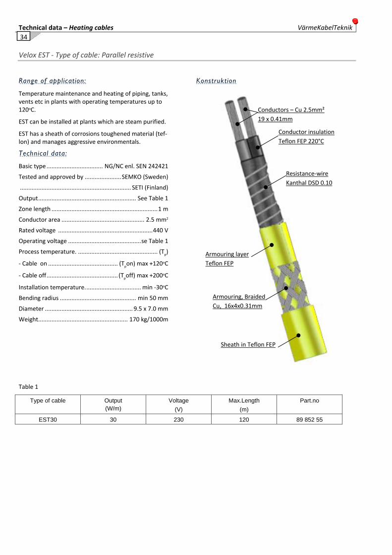
Velox EST ‐ Type of cable: Parallel resistive
Range of application:
Temperature maintenance and heating of piping, tanks, vents etc in plants with operating temperatures up to 120oC.
EST can be installed at plants which are steam purified.
EST has a sheath of corrosions toughened material (tef‐lon) and manages aggressive environmentals.
Technical data:
Basic type .................................. NG/NC enl. SEN 242421
Tested and approved by ...................... SEMKO (Sweden)
................................................................... SETI (Finland)
Output ........................................................... See Table 1
Zone length ................................................................ 1 m
Conductor area .................................................. 2.5 mm2
Rated voltage ......................................................... 440 V
Operating voltage ............................................ se Table 1
Process temperature. ................................................ (Tp)
‐ Cable on .......................................... (Tpon) max +120oC
‐ Cable off ........................................... (Tpoff) max +200oC
Installation temperature. ................................. min ‐30oC
Bending radius .............................................. min 50 mm
Diameter ..................................................... 9.5 x 7.0 mm
Weight ...................................................... 170 kg/1000m
Konstruktion
Table 1
Type of cable Output (W/m)
Voltage (V)
Max.Length (m)
Part.no
EST30 30 230 120 89 852 55
Sheath in Teflon FEP
Armouring, Braided Cu, 16x4x0.31mm
Armouring layer Teflon FEP
Resistance‐wire Kanthal DSD 0.10
Conductor insulationTeflon FEP 220°C
Conductors – Cu 2.5mm² 19 x 0.41mm

VärmeKabelTeknik Technical data – Heating cables
35
Velox EST ‐ Type of cable: Parallel resistive
Sheath temperature
The sheath temperature (Tm) of the cable will vary de‐pending on the process (ambient) temperature (Tp), load (Q) and way of installation.
The sheath temperature is calculated as follows:
Q Tm = _____ +Tp
Ua
Tp = Process temperature in oC
Q = Load in W/m
Ua = Heat transfer coeff.
Example:
Velox EST mounted without dissipation of heat at an ambient temperature of 25oC, output 30 W/m, will have a sheath temperature of 75oC.
Sheath temperature: Diagram 1
Cable installed free in air or against heat conducting material (Ua = 0.6)
Dissipation of heat
The heat transfer coefficient (Ua) can be improved considerably (3 to 10
times) by arranging some dissipation of heat, for instance by providing the cable with aluminium tape or heat conductive concrete at the installation. This will enable you to use the heating cable also where high process tem‐peratures are involved.
For this kind of installation please consult VärmeKabelTeknik for assistance with the design and installation.

Technical data – Heating cables VärmeKabelTeknik 36
Velox PH‐240 V AC ‐ Type of cable: Parallel resistive heating cable
Range of application:
Industrial heating: Pipes, tanks, cisterns.
PHB 240 VAC is teflon insulated and have a sheath of corrosions toughened material (teflon) which manages aggressive environments.
Technical data:
Manufacturing std. /Basic type ........... VDE 253 / EEC800
Tested and approved by .............................................. CE
Test voltage ..................................................... 3000 VDC
Rated voltage ........................................... 220 ‐ 240 VAC
Output ........................................................... 10W / 12W
...................................................................... 20W / 24W
...................................................................... 30W / 36W
Distance between contact points…1 meter
Max. operating temp.. ........................................... 150°C
Max. exposure temp.. ............................................ 200°C
Installation temperature. ................................. min ‐30oC
Bending radius .............................................. min 50 mm
Size ............................................................ 7,8 x 5,6 mm
Weight ..............................................................................
PHB is manufactured with a sheath of Flourplast.
Table 1:
Type of cable Output (W/m)
Length max* (m)
VELOX PH240 -10 10 120
VELOX PH240-20 20 90
VELOX PH240-30 30 75 * at 10% power loss.
Construction
0 °C
50 °C
100 °C
150 °C
200 °C
250 °C
0 10 20 30 40 50 60 70 80 90 100 110 120 130 150
Man
telte
mpe
ratu
r
Process temperatur °C
VELOX PHB
PHB-10 Bare
PHB-10 Alu
PHB-20 Bare
PHB-20 Alu
PHB-30 Bare
PHB-30 Alu
Sheath 2 Fluorplast (FEP)
Sheath Fluorplast (FEP)
Screen copper alloy
Conductor NiCr
Conductor layer
Conductor insulation fluorplast
Conductor copper alloy 1.5mm²

VärmeKabelTeknik Technical data – Heating cables
37
Velox PH‐70 VAC Type of cable: Parallel resistive Double insulated
Range of application: Switch heating at rail-ways, subways, tramways.
PH‐70 is a parallel resistive, teflon insulated heating cable which can be cut at contact points every me‐ter.
Outer sheath made out of corrosive toughened material (teflon)
PH‐70 have double sheath and lacks earth screen.
Technical data:
Manufacturing std./Basic type ........... VDE 253 / EEC800
Approved, tested acc. to .............................................. CE
Colour: ............................................ Orange outer sheath
Test voltage ..................................................... 3000 VDC
Supply voltage ................ 220 / 240 VAC or 110/120 VAC
Output ........................................................... 70W / 84W
Distance between contact points: ...................... 1 meter
Max. Operating temperature .................................150°C
Max. exposure temperature. ..................................200°C
Installation temperature.................................. min ‐30oC
Bending radius ............................................... min 50 mm
Diameter ................................................... 7,8 x 5,6 mm
Weight ........................................................ 75 kg/1000m
Part.no: ................................................. VX503 220‐240V
............................................................... VX50. 110‐120V
Denomination: ...................................... Velox PH‐70 VAC
PH‐70 is manufactured with a sheath of PFA.
Table 1:
Type of cable Output (W/m)
Lengthmax* (m)
VELOX PHB‐70 70 52
* at 10% power loss.
Construction
Insulation
If two cables are installed parallel under same channel, standard channel you will have a constant wattage pa‐rallel resistance cable with output up to 200 W/m.
2 cables installed parallel under channel ref.no 6‐16‐1.
Sheath 2 Fluorplast
Sheath 1 Fluorplast
Bed for
heating con‐ductor
Heating conductor
Ni‐Cr
Conductor insulation
fluorplast
Conductor, tin‐coated Cu, 1.5mm²

Technical data – Heating cables VärmeKabelTeknik 38
Velox PH‐90 VAC ‐ Type of cable: Parallel resistive Double insulated
Range of application:
Switch heating at railways, subways, tramways.
PH‐90 is a parallel resistive, teflon insulated heating cable which can be cut at contact points every me‐ter.
Outer sheath made out of corrosive toughened material (teflon)
PH‐90 have double sheath and lacks earth screen.
Technical data:
Manufacturing std./Basic type ............ VDE 253 / EEC800
Approved, tested av ..................................................... CE
Colour:.................................................. Red outer sheath
Test voltage: ..................................................... 3000 VDC
Supply voltage ................................... 220 / 240 VAC eller
...................................................................... 110 / 120 V
Output ...................................................................... 90W
Distance between contact points: ................... 0.5 meter
Max. Operating temperature ................................. 150°C
Max. exposure temperature. ................................. 230°C
Installation temperature .................................. min ‐30oC
Bending radius .............................................. min 50 mm
Diameter ................................................... 7,8 x 5,6 mm
Weight ........................................................ 75 kg/1000m
Part.no: .................................................. VX50 220‐240V
............................................................... VX50. 110‐120V
Denomination: ...................................... Velox PH‐90 VAC
PH‐90 is manufactured with a sheath of PFA.
Table 1:
Type of cable Output (W/m)
Length max* (m)
VELOX PHB 90 90 52 * at 10% power loss.
Construction
Insulation
If two cables are installed parallel under same channel, standard channel you will have a constant wattage pa‐rallel resistance cable with output up to 200 W/m.
2 cables installed parallel under channel ref.no 6‐16‐1/F
Sheath 2 Fluorplast
Sheath 1 Fluorplast
Bed for
heating con‐ductor
Heating conductor
Ni‐Cr
Conductor insulation
fluorplast
Conductor, tin‐coated Cu, 1.5mm²

VärmeKabelTeknik Technical data – Heating cables
39
Velox PH‐750 VDC ‐ Type of cable: Parallel resistive Double insulated
Range of application:
Switch heating at railways, subways, tramways.
PH‐750 have a double sheath of corrosion hardened material (teflon) and manages aggressive environ‐mentals.
PH‐750 is double insulated without earth.
Technical data:
Basic type ............................................. VDE 253 /EEC800
Approved, tested av..................................................... CE
Colour: ..............................................Green outer sheath
Test voltage ..................................................... 3000 VDC
Supply voltage ................................................... 750 VDC
Output ............................................................... 70W / m
Distance between contact points ....................... 2 meter
Max. Operating temperature .................................180°C
Max. exposure temperature ...................................230°C
Installation temperature.................................. min ‐30oC
Bending radius ............................................... min 50 mm
Diameter ................................................... 7,8 x 5,6 mm
Weight ........................................................ 75 kg/1000m
Part.no: .................................................................. VX504
Denomination: .................................... Velox PH‐750 VDC
Note: PH‐750 VDC is installed on 750 V with a channel of Glasfiber plastic.
Table 1:
Type of cable Output (W/m)
Length max* (m)
VELOX PHB‐750 70 160
* at 10% power loss.
Construction
Insulation
If two cables are installed parallel under same channel, standard channel you will have a constant wattage pa‐rallel resistance cable with output up to 200 W/m.
2 cables installed parallel under channel ref.no 6‐18‐9
Sheath 2 Fluorplast
Sheath 1 Fluorplast
Bed for
heating con‐ductor
Heating conductor
Ni‐Cr
Conductor insulation
fluorplast
Conductor, tin‐coated Cu, 1.5mm²

Technical data – Heating cables VärmeKabelTeknik 40
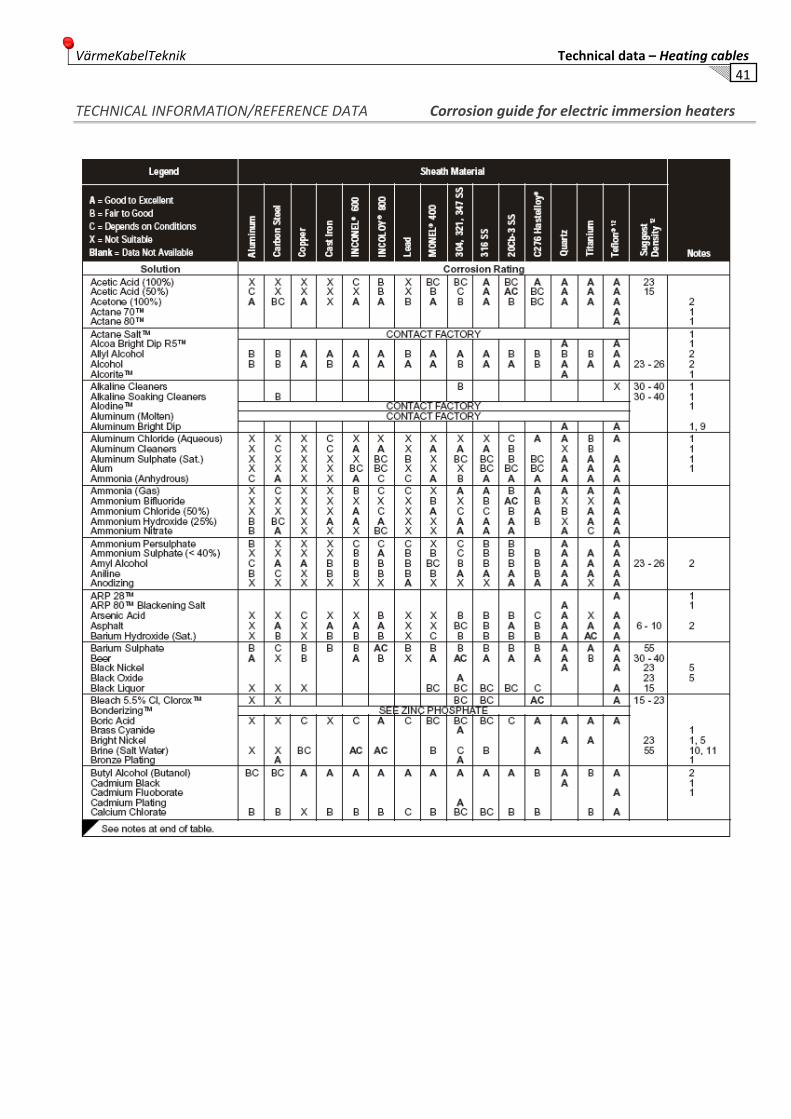
TECHNICAL INFORMATION/REFERENCE DATA Corrosion guide for electric immersion heaters
The following corrosion guide recommendations must not be interpreted as a positive recommendation of your choice of sheath material for electrical immersion heaters. Use this information as a guide in your investi‐gation of your heating process, and arrive at the proper choice based upon your intimate knowledge of the con‐ditions which exist at the job site.
Be very selective in your consideration of heater sheath material. Remember that recommended materials of construction for your tank may not survive as sheathing for the immersion heater. The sheath of an immersion heater function as a heat transfer surface, and thus is operating at temperatures above the control tempera‐ture of the process. Such temperatures and fluid move‐ment impose severe corrosion conditions on the metal surface.
Success of your choise of sheath material will depend upon many factors which are within your power to con‐trol:
1) Control the chemistry of solution.. a. Avoid carry‐over from other processes. b. Control dpletion of bath chemistry. c. Filter or remove accumulating sludge. Sludge im‐ pedes flow of heat from heaters and accelerates cor‐ rosion.
2) Control process temperature. a. Temperature accelerates all corrosion processes. Excess temperatures mean shorter heater life.
3) Avoid contacts between dissimlar metals which could initiate galvanic type corrosion.
4) For safety to personnel against electrical shock, metal sheath heaters must be grounded to the tank and, in turn, to earth. Consider the use of a ground fault circuit interrupter for optimum safety.
5) For processes involving electroplating, immersion heaters must be kept out of the space between anode and cathode where the effects of plating cur‐rent may damage the heater surface.
6) The immersion heaters should be examined period‐ically for corrosion so that corrective action can be taken to maintain continuity of operation.
Notes and legends to corrosion guide
1. This solution involves a mixture of various chemical compounds whose identity and proportions are un‐known or subject to change without our knowledge. Check supplier to confirm choice of sheath material plus alternate sheath materials that may be used.
2. Caution – Flammable material.
3. Chemical composition varies widely. Check supplier for specific recommendations.
4. Direct immersion heaters not practical. Use clamp‐on heaters on outside surface of cast iron pot.
5. Element surface loading should not exceed 20 W/sq.inch.
6. For concentrations greater than 15%, element sur‐face loading should not exceed 20W/sq.inch.
7. See suggested watt density chart.
8. Remove crusts at liquid level.
9. Clean often.
10. Do not exceed 12wpsi.
11. Passivate stainless steel, Inconel and Incoloy
Because so many factors are beyond our control, the VärmeKabelTeknik company cannot be responsible for any electric immersion failure that can be attributed to corrosion. This is in lieu of any warranties, written or verbal, relative to heater performance in a corrosive environment.
VärmeKabelTeknik Technical data – Heating cables
41
TECHNICAL INFORMATION/REFERENCE DATA Corrosion guide for electric immersion heaters
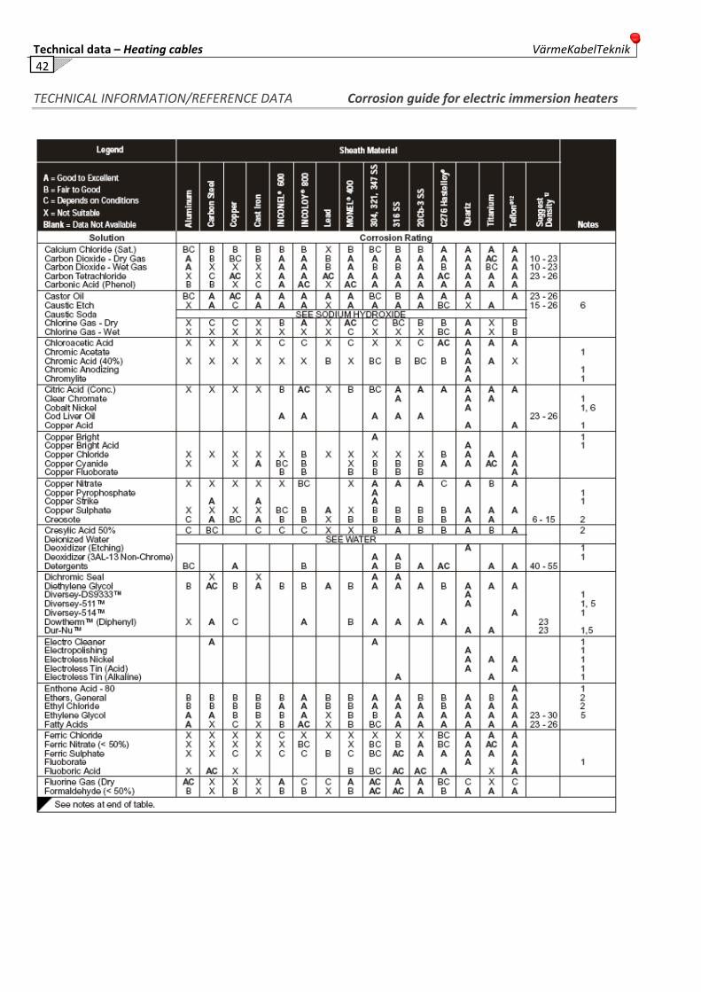
Technical data – Heating cables VärmeKabelTeknik 42
TECHNICAL INFORMATION/REFERENCE DATA Corrosion guide for electric immersion heaters

VärmeKabelTeknik Technical data – Heating cables
43
TECHNICAL INFORMATION/REFERENCE DATA Corrosion guide for electric immersion heaters

Technical data – Heating cables VärmeKabelTeknik 44
TECHNICAL INFORMATION/REFERENCE DATA Corrosion guide for electric immersion heaters

VärmeKabelTeknik Technical data – Heating cables
45
TECHNICAL INFORMATION/REFERENCE DATA Corrosion guide for electric immersion heaters

Technical data – Heating cables VärmeKabelTeknik 46
TECHNICAL INFORMATION/REFERENCE DATA Corrosion guide for electric immersion heaters

VärmeKabelTeknik Technical data – Heating cables
47
TECHNICAL INFORMATION/REFERENCE DATA Corrosion guide for electric immersion heaters

Technical data – Heating cables VärmeKabelTeknik 48
TECHNICAL INFORMATION/REFERENCE DATA Corrosion guide for electric immersion heaters

VärmeKabelTeknik Technical data – Heating cables
49
TECHNICAL INFORMATION/REFERENCE DATA Corrosion guide for electric immersion heaters
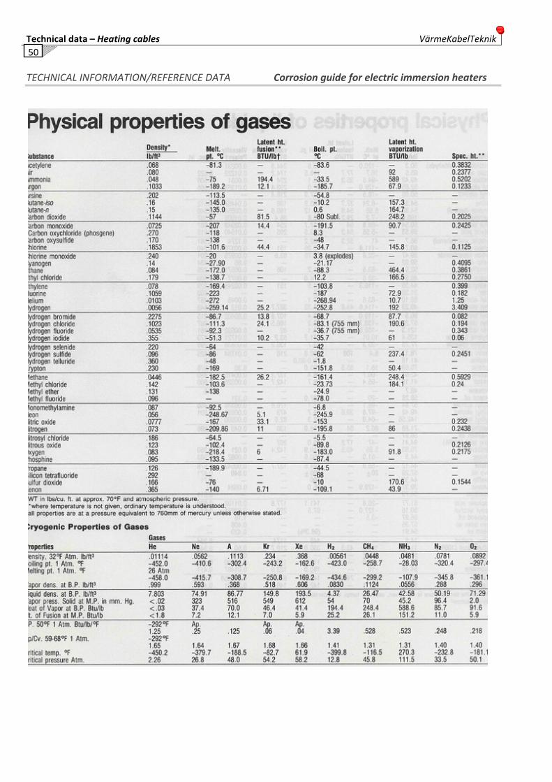
Technical data – Heating cables VärmeKabelTeknik 50
TECHNICAL INFORMATION/REFERENCE DATA Corrosion guide for electric immersion heaters

VärmeKabelTeknik Technical data – Heating cables
51
TECHNICAL INFORMATION/REFERENCE DATA Corrosion guide for electric immersion heaters

Technical data – Heating cables VärmeKabelTeknik 52
TECHNICAL INFORMATION/REFERENCE DATA Corrosion guide for electric immersion heaters

VärmeKabelTeknik Technical data – Heating cables
53
TECHNICAL INFORMATION/REFERENCE DATA Corrosion guide for electric immersion heaters
Technical data – Heating cables VärmeKabelTeknik 54
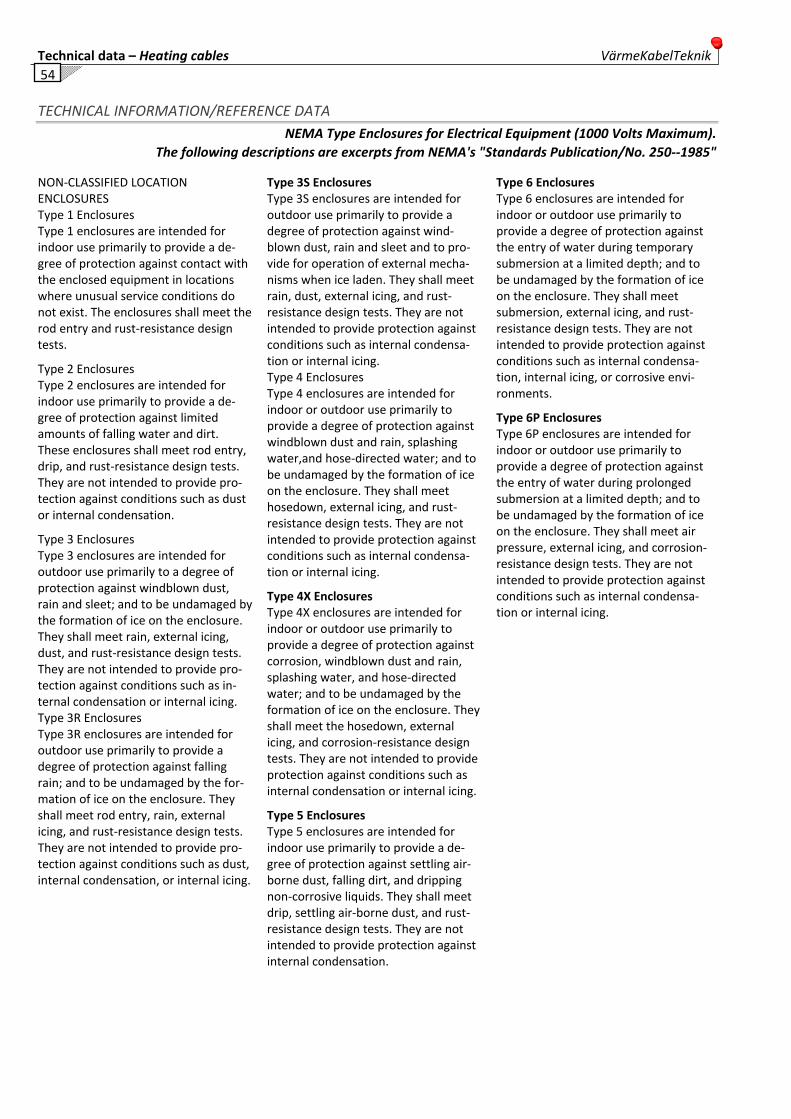
TECHNICAL INFORMATION/REFERENCE DATA NEMA Type Enclosures for Electrical Equipment (1000 Volts Maximum).
The following descriptions are excerpts from NEMA's "Standards Publication/No. 250‐‐1985"
NON‐CLASSIFIED LOCATION ENCLOSURES Type 1 Enclosures Type 1 enclosures are intended for indoor use primarily to provide a de‐gree of protection against contact with the enclosed equipment in locations where unusual service conditions do not exist. The enclosures shall meet the rod entry and rust‐resistance design tests.
Type 2 Enclosures Type 2 enclosures are intended for indoor use primarily to provide a de‐gree of protection against limited amounts of falling water and dirt. These enclosures shall meet rod entry, drip, and rust‐resistance design tests. They are not intended to provide pro‐tection against conditions such as dust or internal condensation.
Type 3 Enclosures Type 3 enclosures are intended for outdoor use primarily to a degree of protection against windblown dust, rain and sleet; and to be undamaged by the formation of ice on the enclosure. They shall meet rain, external icing, dust, and rust‐resistance design tests. They are not intended to provide pro‐tection against conditions such as in‐ternal condensation or internal icing. Type 3R Enclosures Type 3R enclosures are intended for outdoor use primarily to provide a degree of protection against falling rain; and to be undamaged by the for‐mation of ice on the enclosure. They shall meet rod entry, rain, external icing, and rust‐resistance design tests. They are not intended to provide pro‐tection against conditions such as dust, internal condensation, or internal icing.
Type 3S EnclosuresType 3S enclosures are intended for outdoor use primarily to provide a degree of protection against wind‐blown dust, rain and sleet and to pro‐vide for operation of external mecha‐nisms when ice laden. They shall meet rain, dust, external icing, and rust‐resistance design tests. They are not intended to provide protection against conditions such as internal condensa‐tion or internal icing. Type 4 Enclosures Type 4 enclosures are intended for indoor or outdoor use primarily to provide a degree of protection against windblown dust and rain, splashing water,and hose‐directed water; and to be undamaged by the formation of ice on the enclosure. They shall meet hosedown, external icing, and rust‐resistance design tests. They are not intended to provide protection against conditions such as internal condensa‐tion or internal icing.
Type 4X Enclosures Type 4X enclosures are intended for indoor or outdoor use primarily to provide a degree of protection against corrosion, windblown dust and rain, splashing water, and hose‐directed water; and to be undamaged by the formation of ice on the enclosure. They shall meet the hosedown, external icing, and corrosion‐resistance design tests. They are not intended to provide protection against conditions such as internal condensation or internal icing.
Type 5 Enclosures Type 5 enclosures are intended for indoor use primarily to provide a de‐gree of protection against settling air‐borne dust, falling dirt, and dripping non‐corrosive liquids. They shall meet drip, settling air‐borne dust, and rust‐resistance design tests. They are not intended to provide protection against internal condensation.
Type 6 Enclosures Type 6 enclosures are intended for indoor or outdoor use primarily to provide a degree of protection against the entry of water during temporary submersion at a limited depth; and to be undamaged by the formation of ice on the enclosure. They shall meet submersion, external icing, and rust‐resistance design tests. They are not intended to provide protection against conditions such as internal condensa‐tion, internal icing, or corrosive envi‐ronments.
Type 6P Enclosures Type 6P enclosures are intended for indoor or outdoor use primarily to provide a degree of protection against the entry of water during prolonged submersion at a limited depth; and to be undamaged by the formation of ice on the enclosure. They shall meet air pressure, external icing, and corrosion‐resistance design tests. They are not intended to provide protection against conditions such as internal condensa‐tion or internal icing.
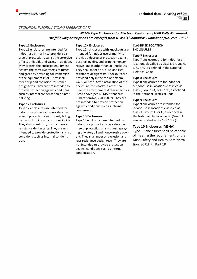
VärmeKabelTeknik Technical data – Heating cables
55
TECHNICAL INFORMATION/REFERENCE DATA NEMA Type Enclosures for Electrical Equipment (1000 Volts Maximum).
The following descriptions are excerpts from NEMA's "Standards Publication/No. 250‐‐1985"
Type 11 Enclosures Type 11 enclosures are intended for indoor use primarily to provide a de‐gree of protection against the corrosive effects or liquids and gases. In addition, they protect the enclosed equipment against the corrosive effects of fumes and gases by providing for immersion of the equipment in oil. They shall meet drip and corrosion‐resistance design tests. They are not intended to provide protection against conditions such as internal condensation or inter‐nal icing.
Type 12 Enclosures Type 12 enclosures are intended for indoor use primarily to provide a de‐gree of protection against dust, falling dirt, and dripping noncorrosive liquids. They shall meet drip, dust, and rust‐resistance design tests. They are not intended to provide protection against conditions such as internal condensa‐tion.
Type 12K EnclosuresType 12K enclosure with knockouts are intended for indoor use primarily to provide a degree of protection against dust, falling dirt, and dripping noncor‐rosive liquids other than at knockouts. They shall meet drip, dust, and rust‐resistance design tests. Knockouts are provided only in the top or bottom walls, or both. After installation of the enclosure, the knockout areas shall meet the environmental characteristics listed above (see NEMA "Standards Publication/No. 250‐1985"). They are not intended to provide protection against conditions such as internal condensation.
Type 13 Enclosures Type 13 enclosures are intended for indoor use primarily to provide a de‐gree of protection against dust, spray‐ing of water, oil and noncorrosive cool‐ant. They shall meet oil exclusion and rust‐resistance design tests. They are not intended to provide protection against conditions such as internal condensation.
CLASSIFIED LOCATIONENCLOSURES
Type 7 Enclosures Type 7 enclosures are for indoor use in locations classified as Class I, Groups A, B, C, or D, as defined in the National Electrical Code.
Type 8 Enclosures Type 8 enclosures are for indoor or outdoor use in locations classified as Class I, Groups A, B, C. or D, as defined in the National Electrical Code.
Type 9 Enclosures Type 9 enclosures are intended for indoor use in locations classified as Class II, Groups E, or G, as defined in the National Electrical Code. (Group F was reinstated in the 1987 NEC).
Type 10 Enclosures (MSHA) Type 10 enclosures shall be capable of meeting the requirements of the Mine Safety and Health Administra‐tion, 30 C.F.R., Part 18
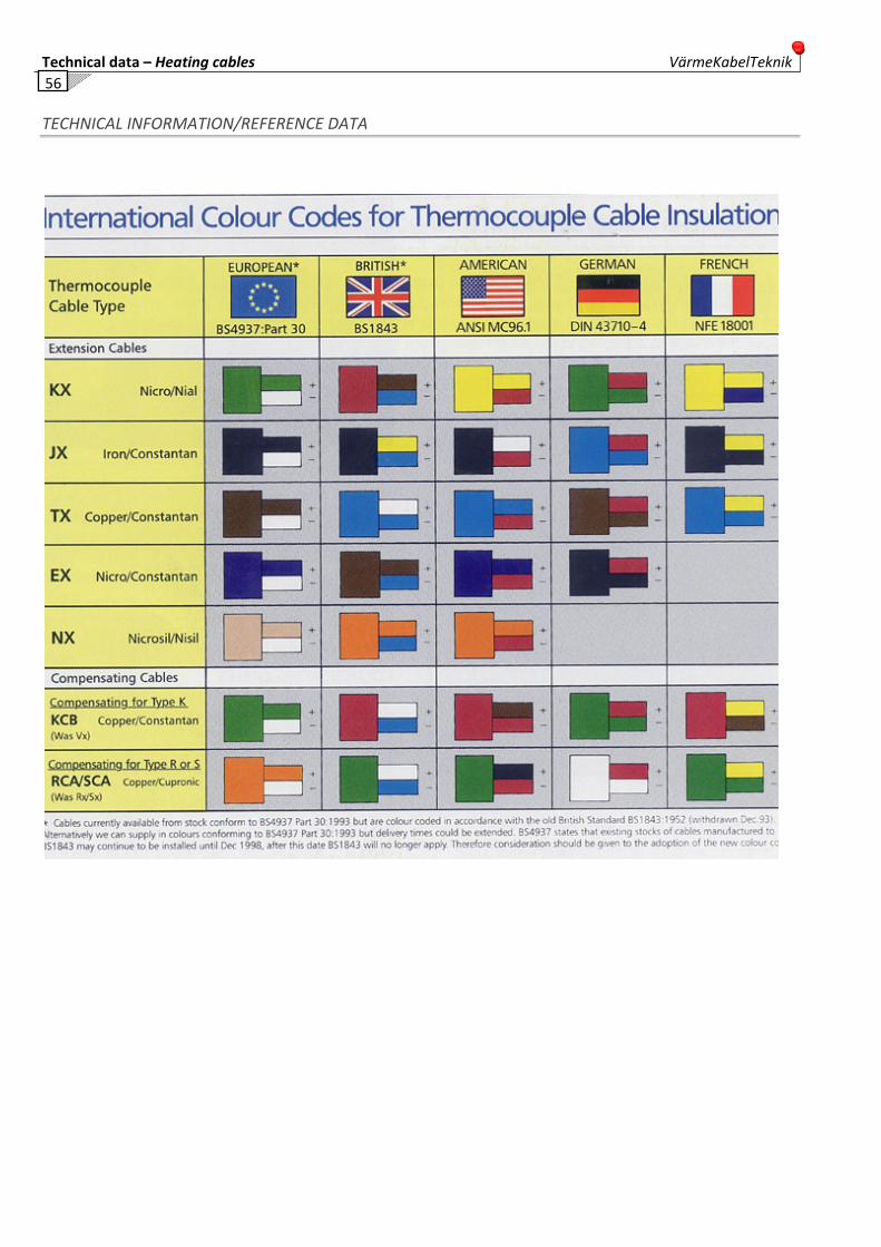
Technical data – Heating cables VärmeKabelTeknik 56
TECHNICAL INFORMATION/REFERENCE DATA

VärmeKabelTeknik Technical data – Heating cables
57
Notes
....................................................................................................................................................................................................
....................................................................................................................................................................................................
....................................................................................................................................................................................................
....................................................................................................................................................................................................
....................................................................................................................................................................................................
....................................................................................................................................................................................................
....................................................................................................................................................................................................
....................................................................................................................................................................................................
....................................................................................................................................................................................................
....................................................................................................................................................................................................
....................................................................................................................................................................................................
....................................................................................................................................................................................................
....................................................................................................................................................................................................
....................................................................................................................................................................................................
....................................................................................................................................................................................................
....................................................................................................................................................................................................
....................................................................................................................................................................................................
....................................................................................................................................................................................................
....................................................................................................................................................................................................
....................................................................................................................................................................................................
....................................................................................................................................................................................................
....................................................................................................................................................................................................
....................................................................................................................................................................................................
....................................................................................................................................................................................................
....................................................................................................................................................................................................
....................................................................................................................................................................................................
....................................................................................................................................................................................................
....................................................................................................................................................................................................
....................................................................................................................................................................................................
....................................................................................................................................................................................................
....................................................................................................................................................................................................
....................................................................................................................................................................................................
....................................................................................................................................................................................................

Technical data – Heating cables VärmeKabelTeknik 58
Telephone: +46‐301‐418 40 – Email: [email protected] – Homepage: www.vkts.se
Industrihuset Södra Hedensbyn 43
S‐430 64 HÄLLINGSJÖ S‐931 91 SKELLEFTEÅ
Sweden Sweden
Fax: +46‐301‐418 70 Fax: +46‐910‐881 33